
MPF980381 - Screwdriver Mac Tools - Free user manual and instructions
Find the device manual for free MPF980381 Mac Tools in PDF.

User questions about MPF980381 Mac Tools
0 question about this device. Answer the ones you know or ask your own.
Ask a new question about this device
Download the instructions for your Screwdriver in PDF format for free! Find your manual MPF980381 - Mac Tools and take your electronic device back in hand. On this page are published all the documents necessary for the use of your device. MPF980381 by Mac Tools.
USER MANUAL MPF980381 Mac Tools
© 2018 Mac Tools

WARNING
To reduce the risk of injury, read and understand these safety warnings and instructions before using the tool. Keep these instructions with the tool for future reference. If you have any questions, contact your MAC TOOLS; representative or distributor.
3/8" Air Impact Wrench | 1/2" Air Impact Wrench | High Performance 3/8" Air Impact Wrench High Performance 1/2" Air Impact Wrench | High Performance 1/2" Compact Air Impact Wrench High Performance 1/2" Air Impact Wrench 2" Extended Anvil
TABLE OF CONTENTS
| Introduction | 2 |
| Safety Instructions 2 - 8 | |
| Maintenance 9 - 10 | |
| Specifications 11 | |
| Tool Components 12 - 19 | |
| Contact Information 21 |
INTRODUCTION
The Mac Tools MPF980381, MPF980501, MPF990381, MPF990501C, MPF990501 and MPF992501 Impact Wrenches are precision-built tools, designed for driving, tightening and loosening threaded fasteners, usually nuts and bolts, when fi tted with a suitable impact socket. These tools will deliver effi cient, dependable service when used correctly and with care. As with any fi ne power tool, for best performance the manufacturer's instructions must be followed. Please study this manual before operating the tool and understand the safety warnings and instructions. The instructions on installation, operation and maintenance should be read carefully, and the manual kept for reference. NOTE: Additional safety measures may be required because of your particular application of the tool. Contact your Mac Tools representative or distributor with any questions concerning the tool and its use.
MACTOOLS.COM | Mac Tools • 505 North Cleveland Avenue • Westerville, Ohio 43082 | 800.MACTOOLS
Mac Tools-Europe, Stanley Black & Decker Inc. • Unit 3, Europa Court Sheffi eld Business Park • Sheffi eld, S9 1XE | 0114 2917266
Definitions: Safety Alert Symbols and Words
This instruction manual uses the following safety alert symbols and words to alert you to hazardous situations and your risk of personal injury or property damage.
A DANGER: Indicates an imminently hazardous situation which, if not avoided, will result in death or serious injury.
A WARNING: Indicates a potentially hazardous situation which, if not avoided, could result in death or serious injury.
CAUTION: Indicates a potentially hazardous situation which, if not avoided, may result in minor or moderate injury.
(A) (Used without word) Indicates a safety related message.
NOTICE: Indicates a practice not related to personal injury which, if not avoided, may result in property damage.
The label on your tool may include the following symbols. The symbols and their definitions are as follows:
V..... volts
Hz ...... hertz
min ......minutes
or DC .....direct current
Class I Construction (grounded)
.../min ......per minute
BPM ...... beats per minute
sfpm......surface feet per minute
SPM ......strokes per minute
A.....amperes
W......watts
\~ or AC ...... alternating current
≈ or AC/DC .. alternating or direct current
☐ Class II Construction (double insulated)
n_0 ...... no load speed
n ...... rated speed
earthing terminal
⚠️ ......safety alert symbol
△......visible radiation
● respiratory protection
eye protection
○.... hearing protection
IPxx......ingress protection
do not incinerate

WARNING
IMPORTANT SAFETY INFORMATION ENCLOSED.
READ THIS MANUAL BEFORE OPERATING THE TOOL.
SAVE FOR FUTURE REFERENCE
FAILURE TO OBSERVE THE FOLLOWING WARNINGS COULD RESULT IN INJURY.

Do not use damaged, frayed or deteriorated air hoses and fittings.

Air powered tools can vibrate in use. Vibration, repetitive motions or uncomfortable positions may be harmful to your hands and arms. Stop using any tool if discomfort, tingling feeling or pain occurs. Seek medical advice before resuming use.

Do not carry the tool by the hose.

Keep body stance balanced and firm. Do not overreach when operating this tool.
Always turn off the air supply and disconnect the air supply hose before installing, removing or adjusting any accessory on this tool, or before performing any maintenance on this tool.

natural_image
Four circular icons representing different types of protective gear: headphones, gloves, boots, and a person wearing sunglasses (no text or symbols)Use protective equipment such as glasses, gloves, safety shoes, as well as acoustic protection.
Remain vigilant, use common sense and pay attention when using the tool.

Always wear ANSI Z87.1 CAN CSA Z94.3 eye protection or for Europe, suitable CE marked eye protection when operating or performing maintenance on this tool.
Always wear suitable respiratory protection when operating this tool.
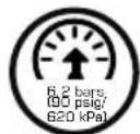
Operate at 90 psig (6.2 bar / 620 kPa) Maximum air pressure.

Do not over-oil and do not use heavy grade oil as stalling and low performance may result.
GENERAL SAFETY INSTRUCTIONS
WARNING: Read all safety warnings and all instructions. Failure to follow the warning and instructions may result in electric shock, fire and or serious injury. SAVE ALL WARNINGS AND INSTRUCTIONS FOR FUTURE REFERENCE
Wear personal protective equipment. Depending on application, use face shield, safety goggles or safety glasses. As appropriate, wear dust mask, hearing protectors, gloves and workshop apron capable of stopping small abrasive or workpiece fragments.
The eye protection must be capable of stopping fl ying debris generated by various operations. The dust mask or respirator must be capable of fi ltrating particles generated by your operation. Prolonged exposure to high intensity noise may cause hearing loss. Everyday eyeglasses are NOT safety glasses. Also use face or dust mask if cutting operation is dusty. ALWAYS WEAR CERTIFIED SAFETY EQUIPMENT:
• ANSI Z87.1 eye protection (CAN/CSA Z94.3)
• ANSI S12.6 (S3.19) hearing protection
• NIOSH/OSHA/MSHA respiratory protection
800.MACTOOLS
1) WORK AREA SAFETY
- Keep work area clean and well lit. Cluttered or dark areas invite accidents. Be aware of your surroundings, slippery surfaces caused by the use of this tool and also of trip hazards caused by air lines.
- Do not operate power tools in explosive atmospheres, such as in the presence of flammable liquids, gases or dust. Power tools create sparks which may ignite the dust or fumes.
- Do not use in wet conditions.
- Keep children and bystanders away while operating a power tool. Distractions can cause you to lose control.
2) PERSONAL SAFETY
- Stay alert, watch what you are doing and use common sense when operating a power tool. Do not use a power tool while you are tired or under the influence of drugs, alcohol or medication. A moment of inattention while operating power tools may result in serious personal injury.
- Prevent unintentional starting. Ensure the trigger is in the off position before connecting to air source, picking up or carrying the tool. Carrying power tools with your finger on the switch or energizing power tools that have the switch on invites accidents.
- Exposure to high noise levels can cause permanent, disabling hearing loss and other problems, such as tinnitus (ringing, buzzing, whistling, or humming in the ears). Therefore, a risk assessment and the implementation of appropriate controls for these hazards are essential. Appropriate controls to reduce the risk may include actions such as damping materials to prevent workpieces from ringing.
- Dress properly. Do not wear loose clothing or jewelry. Keep your hair, clothing and gloves away from moving parts. Loose clothes, rubber-coated or metal reinforced gloves, gloves with cut or frayed fingers, jewelry or long hair can be caught in moving parts.
- Keep hands and other body parts, loose clothing and long hair away from the moving end of tool.
- Anticipate and be alert for sudden changes in motion during start up and operation of any power tool.
- Operators and maintenance personnel must be physically able to handle the bulk, mass and power of the tool.
- Keep body stance balanced and fi rm. Do not overreach when operating this tool.
- Do not operate this tool for long periods of time. Vibration caused by tool action may be harmful to your hands and arms. Hold the tool with a light but safe grip, taking account of the required hand reaction forces. Stop using any tool if discomfort, tingling feeling or pain occurs. Seek medical advice before resuming use.
- This tool is not insulated against electric shock, contact with a live wire will make exposed metal parts live.
- For USA: Some dust created by power sanding, sawing, grinding, drilling, chipping and other construction activities contains chemicals known to the State of California to cause cancer, birth defects or other reproductive harm. Some examples of these chemicals are:
- lead from lead-based paints,
- crystalline silica from bricks and cement and other masonry products, and
- arsenic and chromium from chemically-treated lumber.
Your risk from these exposures varies, depending on how often you do this type of work. To reduce your exposure to these chemicals: work in a well ventilated area, and work with approved safety equipment, such as those dust masks that are specially designed to filter out microscopic particles. - Due to dust generated while using tool, a risk assessment and the implementation of appropriate controls for these hazards are essential.
- Accessories and tools can get hot during operation. Wear gloves when handling them. Ensure the tool is off when changing accessories.
- Keep bystanders a safe distance away from work area. Anyone entering the work area must wear personal protective equipment. Fragments of workpiece or of a broken accessory may fly away and cause injury beyond immediate area of operation.
- Never direct air at yourself or anyone else, or serious personal injury may result.
- Wear warm clothing whenever working in cold conditions and keep your hands warm and dry.
- Whipping hoses can cause severe injury. Always check for damaged or loose hoses and fittings.
- Avoid prolonged contact with dust from power sanding, sawing, grinding, drilling, chipping and other construction activities. Wear protective clothing and wash exposed areas with soap and water. Allowing
dust to get into your mouth, eyes, or lay on the skin may promote absorption of harmful chemicals.
- Use of this tool can generate and/or disperse dust, which may cause serious and permanent respiratory or other injury. Always use NIOSH/OSHA suitable approved respiratory protection appropriate for the dust exposure and suitable extraction systems. Direct particles away from face and body.
- Store idle power tools out of the reach of children and do not allow persons unfamiliar with the power tool or these instructions to operate the power tool. Power tools are dangerous in the hands of untrained users.
- This product may contain one or more chemicals known to the State of California to cause cancer and birth defects or other reproductive harm. Wash hands thoroughly after handling.
- Do not let children come in contact with this tool. Supervision is required when inexperienced operators use this tool.
- Do not modify this tool. Modifications can reduce the effectiveness of safety measures and increase the risks to the operator.
- Do not discard the safety instructions; give them to the operator.
- Do not use the tool if it has been damaged.
- Be aware that the failure of the workpiece or accessories, or even of the tool itself, can generate high-velocity projectiles.
- This product is not intended for use by persons (including children) suffering from diminished physical, sensory or mental abilities; lack of experience, knowledge or skills unless they are supervised by person responsible for their safety. Children should never be left alone with this product. This tool and its accessories must be used in compliance with these instructions. Using it for any other purpose may cause a risk of danger for people and the environment.
- Only qualified and trained operators should install, adjust or use the tool.
- For overhead work, wear a safety helmet.
- Direct the exhaust so as to minimize disturbance of dust in a dust-filled environment. Do not direct exhaust air towards hands.
- Where dust or fumes are created, the priority shall be to control them at the point of emission.
- All integral features or accessories for the collection, extraction or suppression of airborne dust or fumes should be correctly used and maintained in accordance with the manufacturer's instructions.
- Always operate, inspect and maintain this tool in accordance with American National Standards Institute Safety Code for Portable Air Tools (ANSI B186.1) and any other applicable safety codes and regulations.
- Do not free run tool with socket installed on tool.
- Do not splash or immerse in water or other liquids.
- Do not incinerate even if severely damaged or completely worn out. The battery can explode in a fire. Toxic fumes and materials are created when lithium ion batteries are burned.
- If battery contents come into contact with the skin, immediately wash area with mild soap and water. If battery liquid gets into the eye, rinse water over the open eye for 15 minutes or until irritation ceases. If medical attention is needed, the battery electrolyte is composed of liquid organic carbonates and lithium salts.
- Contents of opened battery may cause respiratory irritation. Provide fresh air. If symptoms persist, seek medical attention.
- Burn hazard. Battery liquid may be flammable if exposed to spark or flame.
- Fire hazard. Never attempt to open the battery pack for any reason. If the battery pack case is cracked or damaged, do not insert into the charger. Do not crush, drop or damage the battery pack. Do not use a battery pack or charger that has received a sharp blow, been dropped, run over or damaged in any way (e.g., pierced with a nail, hit with a hammer, stepped on).
- Please note that changes or modifications not expressly approved by the party responsible for compliance could void the user's authority to operate the equipment.
WARNING: Never modify the unit or any part of it. Damage or personal injury could result.
CAUTION: Do not stare into LED light. Serious eye injury could result.
3) ELECTRICAL SAFETY
- Power tool plugs must match the outlet. Never modify the plug in any way. Do not use any adapter plugs with earthed (grounded) power tools. Unmodified plugs and matching outlets will reduce risk of electric shock.
- Do not expose power tools to rain or wet conditions. Water entering a power tool will increase the risk of electric shock.
- Do not abuse the cord. Never use the cord for carrying, pulling or unplugging the power tool. Keep cord away from heat, oil, sharp edges or moving parts. Damaged or entangled cords increase the risk of electric shock.
- If operating a power tool in a damp location is unavoidable, use a ground fault circuit interrupter (GFCI) protected supply. Use of a GFCI reduces the risk of electric shock.
- Recharge only with the charger specified by the manufacturer. A charger that is suitable for one type of battery pack may create a risk of fi re when used with another battery pack.
- Under abusive conditions, liquid may be ejected from the battery; avoid contact. If contact accidentally occurs, fl ush with water. If liquid contacts eyes, additionally seek medical help. Liquid ejected from the battery may cause irritation or burns.
4) ADDITIONAL SPECIFIC SAFETY RULES FOR IMPACT WRENCHES
- Use only impact rated accessory sockets and extensions recommended by Mac Tools. Inspect accessories before use. Do not use cracked or damaged accessories. Do not use chrome sockets, hand sockets or any other accessories not rated for impact use.
- The tool's power is controlled by the pressure exerted on the trigger, firmly grip the tool and squeeze the trigger to operate.
- Do not use sockets with excessive wear to the input or output drives. Periodically check the square drive on the impact wrench. Make sure the socket, extension bar, or other attachment is securely fitted before operating tool.
- When loosening fasteners first ensure that there is sufficient clearance behind the tool to avoid hand entrapment. The tool will move away from the threaded joint as the nut/bolt is loosened and rides up the thread, moving the tool with it. Make sure hands are kept away from the sockets during tool use.
- Securely fit the socket or attachment to the impact wrench. Inspect anvil and retaining ring of tool prior to use. Missing or damaged items should be replaced before use.
- Ensure that the forward/reverse switch is in the correct position for tightening or loosening the fastener.
- The nut/bolt can then run down the thread using the power drive of the tool. For loosening a joint the tool can be used in the reverse sequence.
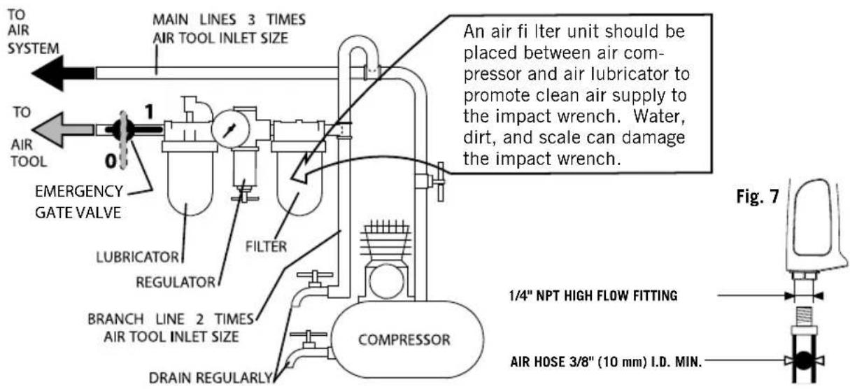
- Recommended to use a hardened steel (or material with comparable shock resistance) threaded hose fitting (Fig 6).
- Before running the tool, check that there is no dangerous interaction with the immediate environment (explosive gas, fl ammable or dangerous liquid, unknown piping, electric sheathing or cable, etc).
- Before connecting the tool to the air inlet, check the trigger is not blocked in the on position by an obstacle.
- In the event of blockage, release the trigger and disconnect the tool from the compressed air network.
- Ensure that the unit on which work is being carried out is immobilized.
- Always operate, inspect and maintain this tool in accordance with all regulations (local, state, federal and country), that may apply to hand held/hand operated pneumatic tool.
- For safety, top performance, and maximum durability of parts, operate this tool at 90 psig. (6.2 bar / 620 kPa) maximum air pressure at the inlet with 3/8" (10mm) inside diameter air supply hose.
• Always use clean, dry air. Dust, corrosive fumes and/or excessive moisture can ruin the motor of an air tool. - Exceeding the maximum pressure of 90 psig (6.2 bar / 620 kPa) will lead to the risk of danger such as excessive speed, tool wear, breaking parts, higher torque or force that may destroy the tool and its accessories or the part being worked on.
- Maintain power tools. Check for misalignment or binding of moving parts, breakage of parts and any other condition that may affect the power tool's operation. If damaged, have the power tool repaired before use. Many accidents are caused by poorly maintained power tools.
- Use rated accessories recommended by Mac Tools only. Inspect accessories before use. Do not use cracked or damaged accessories. Just because the accessory can be attached to your power tool, it does not assure safe operation.
-
Use the power tool, accessories and tool bits, etc. in accordance with these instructions, taking into account the working conditions and the work to be performed. Use of the power tool for operations different from those intended could result in a hazardous situation.
-
Ensure that sparks and debris resulting from use do not create a hazard.
- The pneumatic tool must be fitted and connected to the compressed air network via quick disconnects to facilitate shutdown in the event of danger.
- When the life of the tool has expired, it is recommended that the tool be disassembled, degreased and parts be separated by material so that they can be recycled.
- Always turn off the air supply and disconnect the air supply hose before installing, removing or adjusting any accessory on this tool, or before performing any maintenance on this tool.
- Do not use damaged, frayed or deteriorated air hoses and fittings. Do not abuse hoses or connectors.
- Do not lubricate tools with flammable or volatile liquids such as kerosene, diesel or jet fuel.
- Do not remove any labels. Periodically inspect labels to ensure all marking are still legible. Replace any damaged label.
- Do not use the tool if the trigger does not turn the tool on or off.
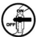
- Do not lock, tape or wire the "on/off" trigger in the "on" position, as this trigger must be free to return to the "off" position when released.
- Be sure all hoses and fittings are the correct size and are tightly secured.
- The use of a hose whip is recommended. A coupler connected directly to the air inlet increases tool bulk and decreases tool maneuverability.
- For maximum performance, the coupler on the wall should be the next size larger than the coupler used on the tool. The coupler closest to the tool should not be less than the proper air supply hose size.
- Use clamps or another practical way to secure and support the workpiece to a stable platform. Holding the work by hand or against the body is unstable and can lead to loss of control.
- When not in use, disconnect tool from air supply to prevent accidental or unauthorized use in the absence of the operator.
- Do not alter any part/component/accessory of this tool in any way.
- Mesh air strainer at air inlet occasionally becomes clogged with debris, blocking air supply, and decreasing the tool's performance. If this occurs the mesh air strainer needs to be cleaned.
- Store idle power tools out of the reach of children and do not allow persons unfamiliar with the power tool or these instructions to operate the power tool. Power tools are dangerous in the hands of untrained users.
- Place the tool on the bolt or nut before starting the tool. Do not point or indulge in any horseplay with this tool.
- Do not store or use in locations where the temperature may reach or exceed 104 °F (40°C) (such as outside sheds or metal buildings in summer). For best life store in a cool, dry location.
IMPORTANT SAFETY INSTRUCTIONS FOR ALL BATTERY CHARGERS
SAVE THESE INSTRUCTIONS: This manual contains important safety and operating instructions for battery chargers.
- Before using the charger, read all instructions and cautionary markings on the charger, battery pack and product using the battery pack.
WARNING: Shock hazard. Do not allow any liquid to get inside the charger. Electric shock may result.
NOTICE: Under certain conditions, with the charger plugged into the power supply, the charger can be shorted by foreign material. Foreign materials of a conductive nature, such as, but not limited to, grinding dust, metal chips, steel wool, magnesium foil or any buildup of metallic particles should be kept away from the charger cavities. Always unplug the charger from the power supply when there is no battery pack in the cavity. Unplug the charger before attempting to clean.
- DO NOT attempt to charge the LED Light Accessory with any chargers other than class 2 chargers. Class 2 chargers and the LED Light Accessory are specifically designed to work together.
- Do not expose the charger to rain or snow.
- Pull by the plug rather than the cord when disconnecting the charger. This will reduce the risk of damage to the electric plug and cord.
- Make sure that the cord is located so that it will not be stepped on, tripped over or otherwise subjected to damage or stress.
- Do not use an extension cord unless it is absolutely necessary. Use of improper extension cord could result in risk of fire, electric shock or electrocution.
800.MACTOOLS
- When operating a charger outdoors, always provide a dry location and use an extension cord suitable for outdoor use. Use of a cord suitable for outdoor use reduces the risk of electric shock.
- Do not operate the charger if it has received a sharp blow, been dropped or otherwise damaged in any way. Take it to an authorized service center
- Do not disassemble the charger; take it to an authorized service center when service or repair is required. Incorrect reassembly may result in a risk of electric shock, electrocution or fire.
- Disconnect the charger from the outlet before attempting any cleaning. This will reduce the risk of electric shock. Removing the LED Light Accessory will not reduce this risk.
- NEVER attempt to connect 2 chargers together.
- The charger is designed to operate on standard 120V household electrical power. Do not attempt to use it on any other voltage. This does not apply to the vehicular charger.
VARIABLE SPEED TRIGGER
To turn the tool on, squeeze the trigger. To turn the tool off, release the trigger. The more you squeeze the trigger, the faster the tool will operate.
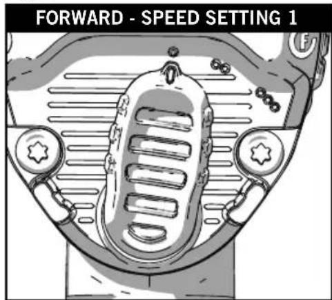
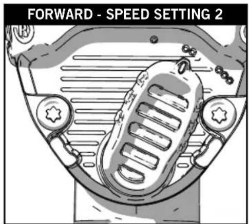
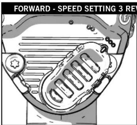
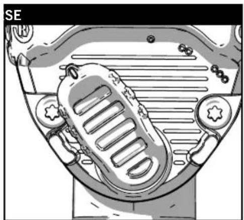
FORWARD/REVERSE AND SPEED CONTROL
The forward/reverse and speed control switch (Fig. 1) determines the direction of the tool and also serves as the variable speed control. To select full speed forward rotation, turn the switch to the far right side of the tool as shown. To select reverse, turn the switch to the far left side of the tool as shown. Please note, reverse is always full power. Forward rotation can be adjusted for variable speed by turning the lever between the three settings as shown in Fig 1, switch will detent in each position.
Fig. 1
natural_image
Illustration of a car's front wheel with visible exhaust pipes and surrounding gear (no text or symbols)LED LIGHT ACCESSORY (included with MPF990381, MPF990501, MPF992501 and MPF990501C)
ATTENTION: LED light accessory must be charged before first use. LED light will not function until charged.
LED light is shipped in sleep mode, charging activates light function. (see charging section below)
Installation and Removal of LED Light
Removal: To remove LED light accessory from tool, rotate the LED light accessory counter clockwise, the LED light will make a 'snap' noise as it rotates. At the top of the nose cone, the unlock symbol will line up with the hash mark when fully unlocked. Pull the LED light accessory straight away from the tool to remove. Charging port is located on the back side of LED light accessory (see charging section below).
Install: To install LED light accessory onto tool, line up the hash mark on top of the nose cone with the unlock symbol. Place LED light accessory onto nose cone toward back of tool until it stops. THEN rotate clockwise, the LED light accessory will make a 'snap' noise as it rotates and locks in place. The hash mark on top of the nose cone will now be lined up with the lock symbol.
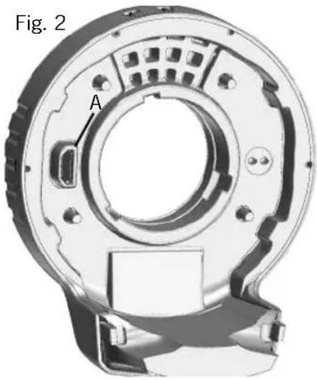
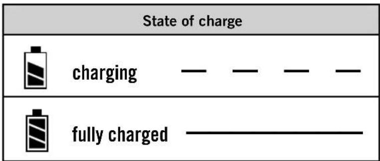
Charging: To charge the unit, connect the USB charging cable into the charging port (A, Fig. 2) on the unit and then plug it in to an appropriate USB port. The AC adaptor can also be used to charge the unit via a standard electrical outlet. Longest life and best performance can be obtained if the battery pack is charged when the air temperature is between 65 °F and 75 °F (18° – 24 °C). DO NOT charge the battery pack in an air temperature below +40 °F (+4.5 °C), or above +105 °F (+40.5 °C). This is important and will prevent serious damage to the battery pack.
NOTE: While the unit is charging, the LED Light will blink continuously indicating that the charging process has started. The completion of charge will be indicated by the LED light remaining ON continuously in a dimmed state. The battery pack is fully charged and may be used at this time or left in the charger. NOTE: To ensure maximum performance and life of lithium-ion battery packs, charge the battery pack fully before first use. The LED Light will fully recharge in 4 hours or less.
natural_image
3D mechanical component diagram labeled Fig. 2, showing internal components and mounting holes (no text or symbols beyond label)CAUTION: Do not stare into LED light. Serious eye injury could result.
There are two LED lights located around the square drive. The LED lights are activated when the trigger switch is depressed.
- On the North American Version, when the trigger is released, the LED light will stay illuminated for up to 5 seconds. If the trigger switch remains depressed, the LED light will remain on.
- On the United Kingdom version, the LED lights will turn off after being illuminated for 20 seconds.
NOTE: The LED Lights are for lighting the immediate work surface and are not intended to be used as a flashlight.
ADAPTOR STATUS INDICATOR
Fig. 3
SERVICE
- Tool service must be performed by qualified repair personnel, using only Mac Tools authorized, identical replacement parts. Use only lubricants recommended by Mac Tools.
800.MACTOOLS
MAINTENANCE
Lubrication
Air tools require lubrication throughout the lifetime of the tools.
This power tool uses compressed air as a power source. The compressed air contains moisture that will rust the components inside of the tools, therefore lubrication is required daily. Failure to lubricate the air tool properly will dramatically shorten the life of the tool and will void the warranty
⚠️ CAUTION: This air tool requires lubrication BEFORE initial use, also before and after each additional use.
To lubricate the air tool manually:
-
Disconnect the tool from the air supply source, place the air inlet face up.
-
Depress the trigger and place about 5 to 10 drops (0.25 to 0.5 ml) of air tool oil into the air inlet.
NOTE: Use SAE #10 weight oil if air tool oil is not available.
- Remove accessory, connect the tool to an air source, then cover the exhaust end with a towel and run tool for 2 to 3 seconds.
To lubricate internal mechanism:
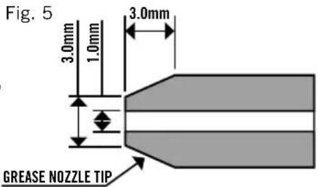
Locate the grease fi tting on the back of the tool (fi g. 4). Inject 4 grams of Mac Tools approved impact grease into the fi tting every 3-5 months depending on use. Use recommended grease gun nozzle tip (fi g. 5) on grease fi tting, smaller or sharp nozzle will damage grease fi tting ball bearing
Fig. 4
natural_image
Diagram of a car's front wheel and side seat assembly (no text or labels)⚠ WARNING: Keep out of the reach of children. If air tool oil is ingested, do not induce vomiting, call a doctor immediately.
⚠ WARNING: Any excess oil in the tool is immediately expelled from the exhaust port. Always direct exhaust port away from people or objects.
NOTE: Check the speed and make a simple check of the vibration level after each service.
Storage: The air tool must be lubricated before storing. Follow the "Lubrication" instruction with exception of step 3.
Always use an air line lubricator with this tool. Do not over-oil and do not use heavy grade oil as stalling and low performance may result.
PLACING TOOL IN SERVICE
Fig. 6

WARNING
⚠ WARNING: To reduce the risk of serious personal injury, ALWAYS use proper hand position as shown (Fig. 8).
⚠ WARNING: To reduce the risk of serious personal injury, ALWAYS hold securely in anticipation of a sudden reaction.
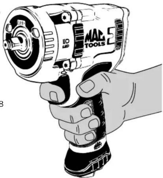
natural_image
Illustration of a hand holding a MAC Tool with a power drill (no text or symbols on the tool itself)Fig. 8
| SPECIFICATIONS | |||||||
| Model # | Square Drivein / mm | Impact Ratebpmfwd / rev | Breakaway Torqueft-lbs / Nm Pressure dB(A) Power dB(A) | ||||
| MPF980381 | 375 / 9.5 1300 | / 1400 575 / 780 | 95 3* 107 3* | ||||
| MPF980501 | 5 / 13 1200 / 13 | 300 1180 / 1600 | 93 3* 104 3* | ||||
| MPF990381 | 375 / 9.5 1300 | / 1400 700 / 950 | 95 3* 107 3* | ||||
| MPF990501 | 5 / 13 1100 / 12 | 200 1400 / 1898 | 94 3* 105 3* | ||||
| MPF990501C | 5 / 13 1300 / 14 | 400 700 / 950 95 | 3* 107 3* | ||||
| MPF992501 | 5 / 13 1100 / 12 | 200 1400 / 1898 | 93 3* 104 3* | ||||
| Model # | Vibration Level (ISO 28927-2) m/s ^2 | Average Air Consumption cfm / l/min psi | Working Pressure / bar lbs / kg | Weight Dimensions n / mm | ||
| MPF980381 3 | .0 | 1.5** | 5.9 / 167 | 90 / 6.2 | 2.8 / 1.3 | 5.6 x 2.5 x 7.8 / 143 x 62.5 x 197 |
| MPF980501 6 | .2 | 2.5** | 6.1 / 172 | 90 / 6.2 | 4.4 / 2 | 6.4 x 3 x 8.3 / 162 x 75.3 x 212 |
| MPF990381 | 3.9 | 1.5** | 5.9 / 167 | 90 / 6.2 | 3 / 1.4 | 5.6 x 2.5 x 7.8 / 143 x 62.5 x 197 |
| MPF990501 | 6.4 | 2.2** | 6.1 / 172 | 90 / 6.2 | 4.8 / 2.2 | 6.4 x 3 x 8.3 / 162 x 75.3 x 212 |
| MPF990501C | 3.9 | 1.5** | 5.9/167 | 90 / 6.2 | 3 / 1.4 | 5.7 x 2.5 x 7.8 / 144 x 62.5 x 197 |
| MPF992501 | 7.1 | 2.1** | 6.1 / 172 | 90 / 6.2 | 5 / 2.3 | 8.3 x 3 x 8.3 / 212 x 75.3 x 212 |
* = measurement uncertainty in dB(A)
** = measurement uncertainty in m/s²

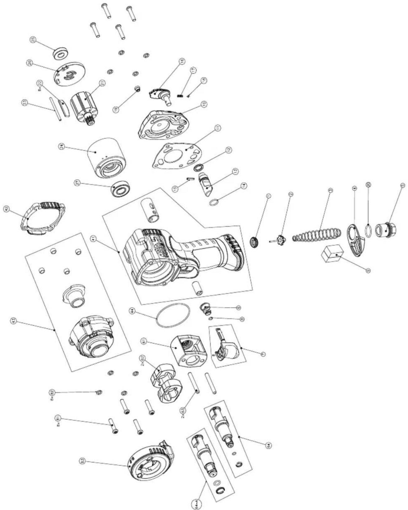
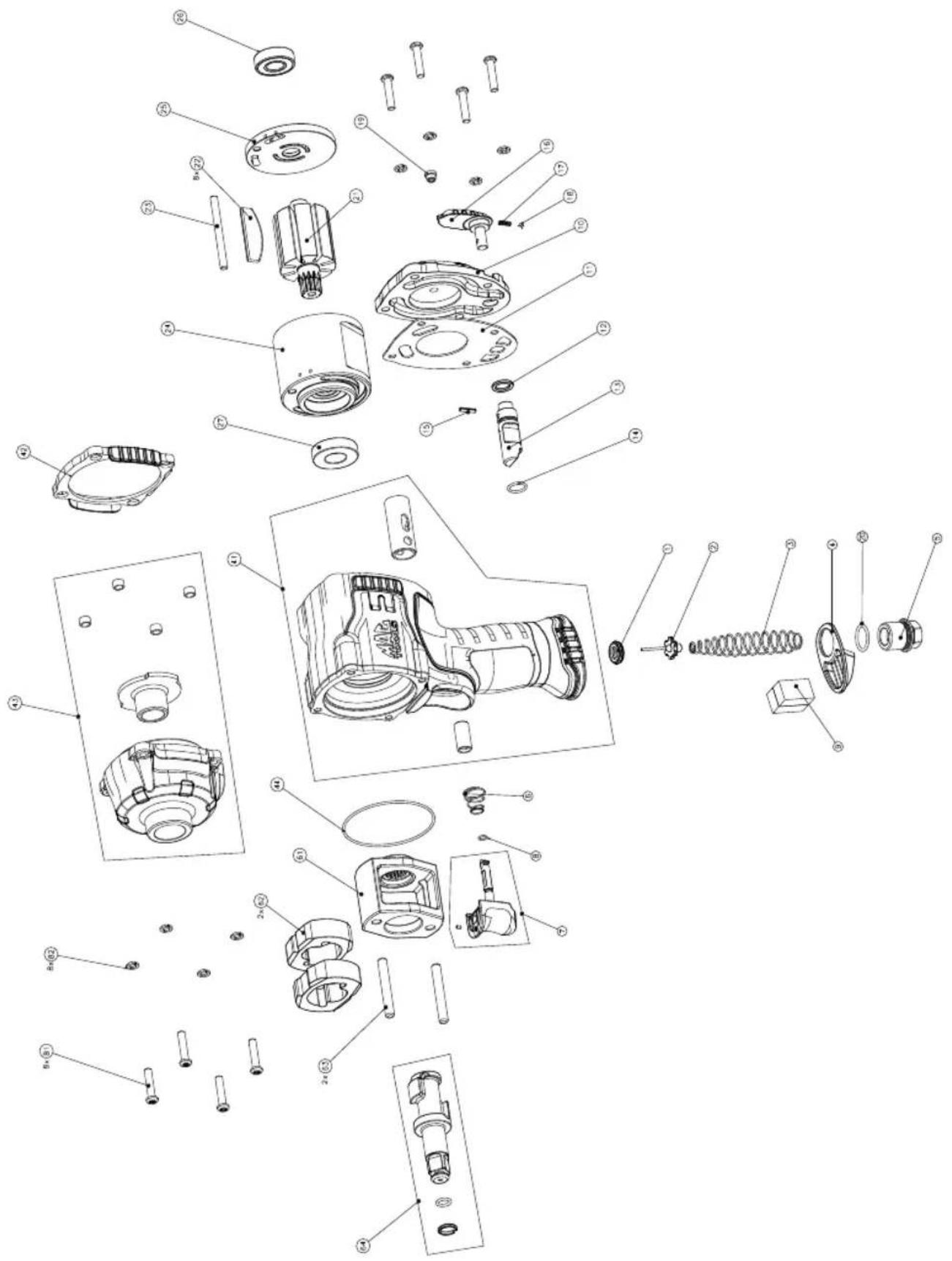
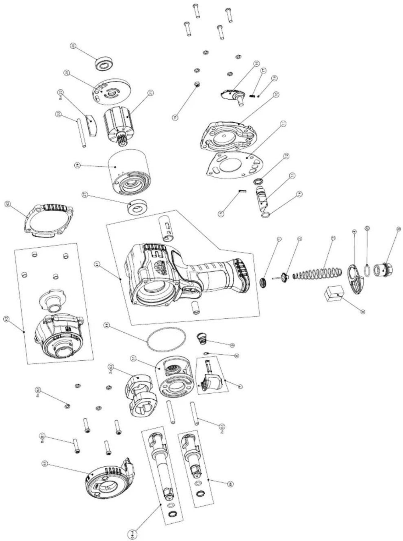
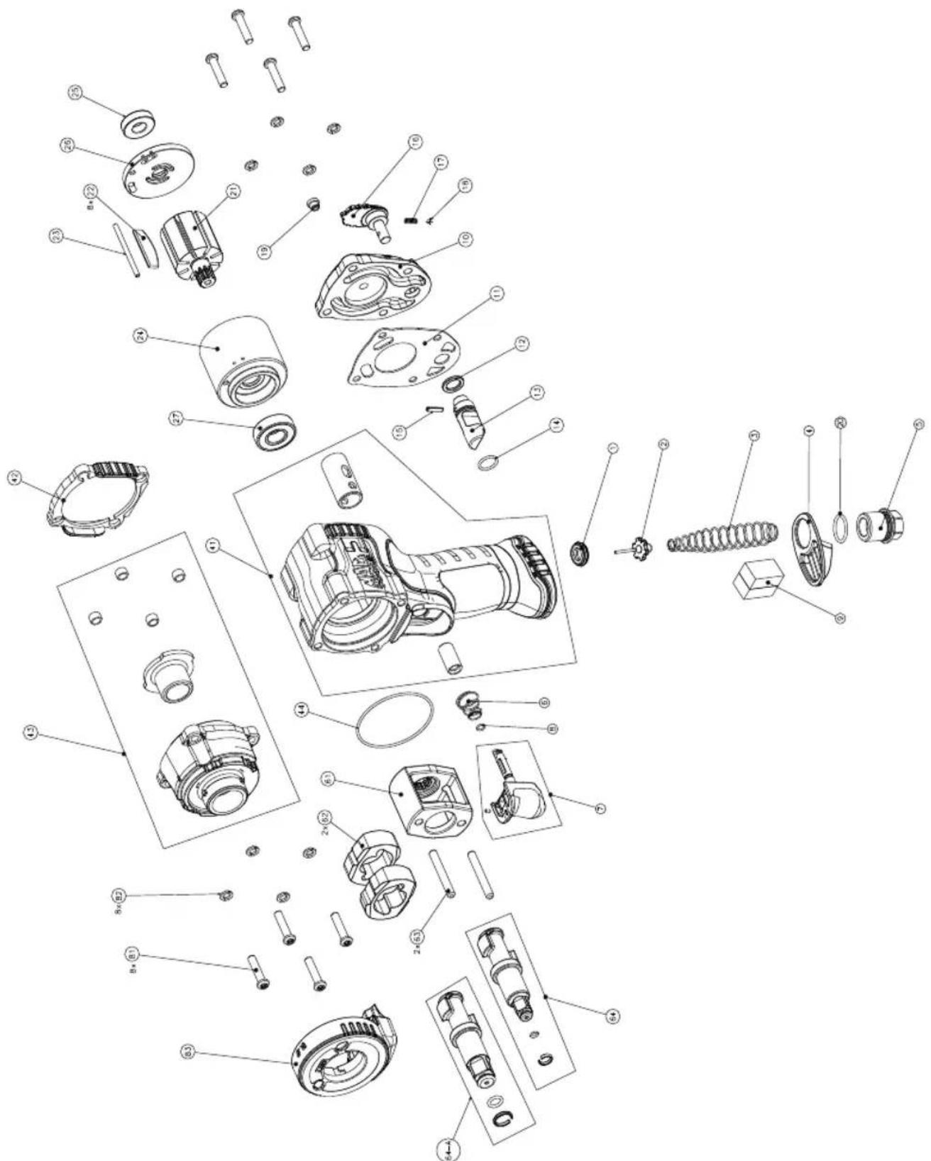
| ITEM # | PART # DESCRIPTION | ION QTY | |
| 27 | N472554 BALL BEARING | 1 | |
| 41 | N533961 HOUSING ASSEMBLY | 1 | |
| VALVE SLEEVE | 1 | ||
| TRIGGER SLEEVE | 1 | ||
| 42 | N488301 FRONT GASKET | 1 | |
| 43 | N533950 HAMMER CASE ASSEMBLY | 1 | |
| SLEEVE | 1 | ||
| SPACER | 4 | ||
| 44 | N554255 O-RING 1 | ||
| 61 | N471004 FRAME | 1 | |
| 62 | N471003 HAMMER | 2 | |
| 63 | N471005 PIN | 2 | |
| 64 | N527950 3/8" ANVIL ASSEMBLY | 1 | |
| O-RING 1 | |||
| HOG RING | 1 | ||
| 81 | N470995 SCREW | 8 | |
| 82 | N470996 WASHER | 8 |
| ITEM # | PART # | DESCRIPTION | ION QTY | |
| MPF980381 3/8" AIR IMPACT WRENCH | ||||
| 1 N53 | 9593 GASKET 1 | |||
| 2 N46 | 3044 THROTTLE | VALVE 1 | ||
| 3 N46 | 3048 THROTTLE | VALVE SPRING 1 | ||
| 4 N47 | 1027 EXHAUST 1 | |||
| 5 N49 | 5010 AIR INLET 1 | |||
| 6 N49 | 6835 TRIGGER FRONT BIAS SPRING 1 | |||
| 7 N54 | 8975 TRIGGER 1 | |||
| 8 N47 | 0999 O-RING 1 | |||
| 9 N56 | 6303 OILER FELT 1 | |||
| 10 | N497317 BACK CAP | 1 | ||
| 11 | N488302 REAR GASKET | 1 | ||
| 12 | N471020 VALVE RUBBER SEAL | 1 | ||
| 13 | N497986 VALVE | 1 | ||
| 14 | N470994 O-RING 1 | |||
| 15 | N488303 ROLL PIN 1 | |||
| 16 | N494372 THUMB PADDLE | 1 | ||
| 17 | N471026 DETENT SPRING | 1 | ||
| 18 | N471025 DETENT BALL ∅3MM | 1 | ||
| 19 | N463039 GREASE FITTING | 1 | ||
| 20 | 86459 | O-RING 1 | ||
| 21 | N471031 ROTOR | 1 | ||
| 22 | N573342 ROTOR BLADE | 8 | ||
| 23 | N471017 DOWEL | 1 | ||
| 24 | N488315 CYLINDER | 1 | ||
| 25 | N488319 REAR END PLATE | 1 | ||
| 26 | N461671 BALL BEARING | 1 | ||
| ITEM # | PART # DESCRIPTION QTY | ||
| 26 | N461671 BALL BEARING | 1 | |
| 27 | N472554 BALL BEARING | 1 | |
| 41 | N533957 HOUSING ASSEMBLY | 1 | |
| VALVE SLEEVE | 1 | ||
| TRIGGER SLEEVE | 1 | ||
| 42 | N488301 FRONT GASKET | 1 | |
| 43 | N533949 HAMMER CASE ASSEMBLY | 1 | |
| SLEEVE | 1 | ||
| SPACER | 1 | ||
| 44 | N554255 | O-RING | 1 |
| 61 | N471004 FRAME | 1 | |
| 62 | N471003 HAMMER | 2 | |
| 63 | N471005 PIN | 2 | |
| 64 | N527950 3/8" ANVIL ASSEMBLY | 1 | |
| O-RING 1 | |||
| HOG RING | 1 | ||
| 64-A | N527951 1/2" ANVIL ASSEMBLY | 1 | |
| O-RING 1 | |||
| HOG RING | 1 | ||
| 81 | N470995 SCREW | 8 | |
| 82 | N470996 WASHER | 8 | |
| 83 | N516144 LIGHT MODULE | 1 | |
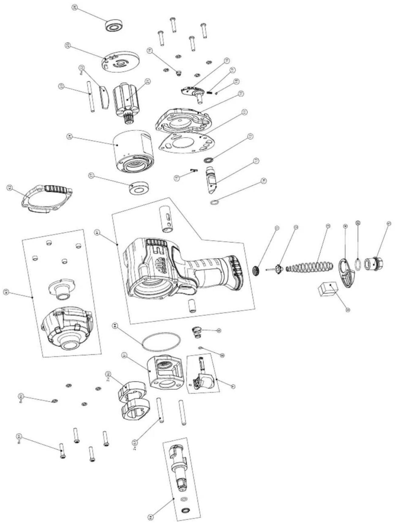
| ITEM # | PART # DESCRIPTION QTY | ||
| MPF990381/ MPF990501C | HIGH PERFORMANCE 3/8" IMPACT WRENCH HIGH PERFORMANCE 1/2" COMPACT IMPACT WRENCH | ||
| 1 N53 | 9593 GASKET 1 | ||
| 2 N46 | 3044 THROTTLE VALVE 1 | ||
| 3 N46 | 3048 THROTTLE VALVE SPRING 1 | ||
| 4 N47 | 1027 EXHAUST 1 | ||
| 5 N49 | 5010 AIR INLET 1 | ||
| 6 N49 | 6835 TRIGGER FRONT BIAS SPRING 1 | ||
| 7 N54 | 8975 TRIGGER 1 | ||
| 8 N47 | 0999 O-RING 1 | ||
| 9 N56 | 6303 OILER FELT 1 | ||
| 10 | N497317 BACK CAP | 1 | |
| 11 | N488302 REAR GASKET | 1 | |
| 12 | N471020 VALVE RUBBER SEAL | 1 | |
| 13 | N497986 VALVE | 1 | |
| 14 | N470994 O-RING 1 | ||
| 15 | N488303 ROLL PIN 1 | ||
| 16 | N494372 THUMB PADDLE | 1 | |
| 17 | N471026 DETENT SPRING | 1 | |
| 18 | N471025 DETENT BALL ∅3MM | 1 | |
| 19 | N463039 GREASE FITTING | 1 | |
| 20 | 86459 | O-RING 1 | |
| 21 | N471006 ROTOR | 1 | |
| 22 | N573340 ROTOR BLADE | 8 | |
| 23 | N471017 DOWEL | 1 | |
| 24 | N488314 CYLINDER | 1 | |
| 25 | N488319 REAR END PLATE | 1 | |
| ITEM # | PART # DESCRIPTION QTY | ||
| 26 | N472554 BALL BEARING | 1 | |
| 27 | N470976 BALL BEARING | 1 | |
| 41 | N533952 HOUSING ASSEMBLY | 1 | |
| VALVE SLEEVE | 1 | ||
| TRIGGER SLEEVE | 1 | ||
| 42 | N471021 FRONT GASKET | 1 | |
| 43 | N533948 HAMMER CASE ASSEMBLY 1 | ||
| SLEEVE | 1 | ||
| SPACER | 1 | ||
| 44 | N554257 O-RING 1 | ||
| 61 | N471033 FRAME | 1 | |
| 62 | N548966 HAMMER | 2 | |
| 63 | N470969 PIN | 2 | |
| 64 | N527948 1/2" ANVIL ASSEMBLY | 1 | |
| O-RING 1 | |||
| HOG RING | 1 | ||
| 81 | N470995 SCREW | 8 | |
| 82 | N470996 WASHER | 8 | |
| ITEM # | ART # DESCRIPTION QTY | ||
| MPF980501 1/2" IMPACT WRENCH | |||
| 1 N53 | 9593 GASKET 1 | ||
| 2 N46 | 3044 THROTTLE | VALVE 1 | |
| 3 N46 | 3048 THROTTLE | VALVE SPRING 1 | |
| 4 N47 | 1027 EXHAUST 1 | ||
| 5 N49 | 5010 AIR INLET 1 | ||
| 6 N49 | 6835 TRIGGER | FRONT BIAS SPRING 1 | |
| 7 N54 | 8975 TRIGGER 1 | ||
| 8 N47 | 0999 O-RING 1 | ||
| 9 N56 | 6303 OILER FELT 1 | ||
| 10 | N470981 BACK CAP | 1 | |
| 11 | N471022 REAR GASKET | 1 | |
| 12 | N471020 VALVE RUBBER SEAL | 1 | |
| 13 | N488321 VALVE | 1 | |
| 14 | N470994 O-RING 1 | ||
| 15 | N488303 ROLL PIN 1 | ||
| 16 | N488323 THUMB PADDLE | 1 | |
| 17 | N471026 DETENT SPRING | 1 | |
| 18 | N471025 DETENT BALL ∅3MM | 1 | |
| 19 | N463039 GREASE FITTING | 1 | |
| 20 | 86459 | O-RING 1 | |
| 21 | N471034 ROTOR | 1 | |
| 22 | N573341 ROTOR BLADE | 8 | |
| 23 | N470989 DOWEL | 1 | |
| 24 | N488312 CYLINDER | 1 | |
| 25 | N488317 REAR END PLATE | 1 | |
| ITEM # | PART # | DESCR | PTION QTY | |
| 26 N4 | 72554 | BALL BEARING | 1 | |
| 27 N4 | 70976 | BALL BEARING | 1 | |
| 41 N5 | 33951 | HOUSING ASSEMBLY | 1 | |
| VALVE SLEEVE | 1 | |||
| TRIGGER SLEEVE | 1 | |||
| 42 N4 | 71021 | FRONT GASKET | 1 | |
| 43 N4 | 91765 | HAMMER CASE ASSEMBLY | 1 | |
| SLEEVE | 1 | |||
| SPACER | 1 | |||
| 44 N5 | 54257 | O-RING 1 | ||
| 61 N4 | 70968 | FRAME | 1 | |
| 62 N5 | 48966 | HAMMER | 2 | |
| 63 N4 | 70969 | PIN | 2 | |
| 64 N5 | 27948 | 1/2" ANVIL ASSEMBLY | 1 | |
| O-RING 1 | ||||
| HOG RING | 1 | |||
| 64-A | N527949 | 1/2" EXTENDED ANVIL ASSEMBLY | 1 | |
| O-RING 1 | ||||
| HOG RING | 1 | |||
| 81 N4 | 70995 | SCREW | 8 | |
| 82 N4 | 70996 | WASHER | 8 | |
| 83 N4 | 94860 | LIGHT MODULE | 1 | |
| 86 N4 | 71020 | VALVE RUBBER SEAL | 1 |
| ITEM # | PART # DESCR | PTION QTY | |
| MPF990501/MPF992501 | HIGH PERFORMANCE 1/2" IMPACT WRENCHHIGH PERFORMANCE 1/2" EXTENDED IMPACT WRENCH | ||
| 1 N53 | 9593 GASKET | 1 | |
| 2 N46 | 3044 THROTTLE VALVE | 1 | |
| 3 N46 | 3048 THROTTLE VALVE SPRING | 1 | |
| 4 N47 | 1027 EXHAUST | 1 | |
| 5 N49 | 5010 AIR INLET | 1 | |
| 6 N49 | 6835 TRIGGER | FRONT BIAS SPRING | 1 |
| 7 N54 | 8975 TRIGGER | 1 | |
| 8 N47 | 0999 O-RING | 1 | |
| 9 N56 | 6303 OILER FELT | 1 | |
| 10 N47 | 0981 BACK CAP | 1 | |
| 11 N47 | 1022 REAR GASKET | 1 | |
| 12 N47 | 1020 VALVE RUBBER SEAL | 1 | |
| 13 N48 | 8321 VALVE | 1 | |
| 14 N47 | 0994 O-RING | 1 | |
| 15 N48 | 8303 ROLL PIN | 1 | |
| 16 N48 | 8323 THUMB PADDLE | 1 | |
| 17 N47 | 1026 DETENT SPRING | 1 | |
| 18 N47 | 1025 DETENT BALL ∅3MM | 1 | |
| 19 N46 | 3039 GREASE FITTING | 1 | |
| 20 | 86459 | O-RING | 1 |
| 21 N47 | 0970 ROTOR | 1 | |
| 22 N57 | 3343 ROTOR BLADE | 8 | |
| 23 N47 | 0989 DOWEL | 1 | |
| 24 N48 | 8311 CYLINDER | 1 | |
| 25 N48 | 8317 REAR END PLATE | 1 |
COMPLIANCE
This device is CAN ICES-3(B)/NMB-3(B) compliant.
This device complies with Part 15 of the FCC rules and Industry Canada License-exempt RSS standard(s).
Operation is subject to the following two conditions:
This device may not cause harmful interference, and
This device must accept any interference received, including interference that may cause undesired operation.
This equipment has been tested and found to comply with the limits for a Class B digital device, pursuant to Part 15 of the FCC Rules. These limits are designed to provide reasonable protection against harmful interference in a residential installation. This equipment generates, uses, and can radiate radio frequency energy and, if not installed and used in accordance with the instructions, may cause harmful interference to radio communications. However, there is no guarantee that interference will not occur in a particular installation.
If this equipment does cause harmful interference to radio or television reception, which can be determined by turning the equipment off and on, the user is encouraged to try to correct the interference by one of the following measures:
Reorient or relocate the receiving antenna.
Increase the separation between the equipment and receiver.
Connect the equipment into an outlet on a circuit different from that to which the receiver is connected.
Consult the dealer or an experienced radio/TV technician for help.
THE RBRC® SEAL

The RBRC ^® (Rechargeable Battery Recycling Corporation) Seal on the nickel cadmium, nickel metal hydride or lithium-ion batteries (or battery packs) indicates that the costs to recycle these batteries (or battery packs) at the end of their useful life have already been paid by Mac Tools. In some areas, it is illegal to place spent nickel cadmium, nickel metal hydride or lithium-ion batteries in the trash or municipal solid waste stream and the Call 2 Recycle ^® program provides an environmentally conscious alternative.
Call 2 Recycle, Inc., in cooperation with Mac Tools and other battery users, has established the program in the United States and Canada to facilitate the collection of spent nickel cadmium, nickel metal hydride or lithium-ion batteries. Help protect our environment and conserve natural resources by returning the spent nickel cadmium, nickel metal hydride or lithium-ion batteries to an authorized Mac Tools service center or to your local retailer for recycling. You may also contact your local recycling center for information on where to drop off the spent battery. RBRC ^® is a registered trademark of Call 2 Recycle, Inc.
LIMITED WARRANTY
We warrant that this tool shall be free from manufacturing defects for a period of ONE YEAR from the original purchase date. Our obligation to the original purchaser shall be limited to repairing or replacing, at our expense (not including shipping charges) a defective tool if returned by the original purchaser within one year from the date of purchase, all incoming shipping charges prepaid. THIS WARRANTY DOES NOT COVER DEFECTS OR DAMAGES TO THE TOOL (i) after the warranty period expires; (ii) resulting from misuse or abnormal operation; (iii) resulting from a failure to properly lubricate, maintain or operate the tool; or (iv) resulting from any repair or maintenance services performed by any party other than Mac Tools. THIS LIMITED WARRANTY IS GIVEN IN LIEU OF ALL OTHERS, INCLUDING THE IMPLIED WARRANTY OF MERCHANTABILITY AND FITNESS FOR A PARTICULAR PURPOSE, AND EXCLUDES ALL INCIDENTAL OR CONSEQUENTIAL DAMAGES. Some states do not allow limitations on how long an implied warranty lasts or the exclusion or limitation of incidental or consequential damages, so these limitations may not apply to you. This warranty gives you specific legal rights and you may have other rights which vary in certain states or provinces.
CUSTOMER SERVICE
We at Mac Tools are committed to our customers, please reference the following phone number for a direct contact to one of our customer technicians. They will be more than happy to help with any service or warranty questions you may have about your power tool.
MACTOOLS.COM | Mac Tools • 505 North Cleveland Avenue • Westerville, Ohio 43082 | 800.MACTOOLS
Mac Tools-Europe, Stanley Black & Decker Inc. • Unit 3, Europa Court
Sheffi eld Business Park• Sheffi eld, S9 1XE | 0114 2917266
CE DECLARATION OF CONFORMITY
WE, MAC TOOLS EUROPE-STANLEY BLACK & DECKER, INC. EUROPA COURT, SHEFFIELD BUSINESS PARK, SHEFFIELD S9 1XE, UNITED KINGDOM, DECLARE UNDER OUR OWN RESPONSIBILITY THAT THE PRODUCTS MPF980381 – 0.375 IN IMPACT WRENCH, MPF980501 – 0.5 IN IMPACT WRENCH, MPF990381– HIGH PERFORMANCE 0.375 IN IMPACT WRENCH, MPF990501 – HIGH PERFORMANCE 0.5 IN IMPACT WRENCH, MPF990501C – HIGH PERFORMANCE 0.5 IN COMPACT IMPACT WRENCH, MPF992501 – HIGH PERFORMANCE 0.5 IN IMPACT WRENCH 2 IN EXTENDED ANVIL
- ARE IN CONFORMITY WITH THE "MACHINERY" DIRECTIVE 2006/42/EC
- AND ARE IN CONFORMITY WITH THE PROVISIONS OF THE HARMONISED EUROPEAN STANDARD EN ISO 11148-6: 2012
THE UNDERSIGNED IS RESPONSIBLE FOR COMPILATION OF THE TECHNICAL FILE AND MAKES THIS DECLARATION ON BEHALF OF MAC TOOLS.
CE

Markus Rompel Director Engineering 25.04.2017
©2018 Mac Tools Patent pending
MAC TOOLS®
MPF980381, MPF980501, MPF990381, MPF990501C, MPF990501, MPF992501
MACTOOLS.COM | Mac Tools • 505 North Cleveland Avenue • Westerville, Ohio 43082 | 800.MACTOOLS
Mac Tools-Europe, Stanley Black & Decker Inc. • Unit 3, Europa Court
Sheffi eld Business Park• Sheffi eld, S9 1XE| 0114 2917266
natural_image
Four circular icons representing different types of protective gear: headphones, gloves, boots, and a person wearing sunglasses (no text or symbols)| No. DE ARTÍCULO | No. DE PIEZA D | DESCRIPCIÓN CTD | |
| 25 N488319 PLACA DEL EXTREMO TRASERO | 1 | ||
| 26 N461671 RODAMIENTO DE BOLA | 1 | ||
| 27 N472554 RODAMIENTO DE BOLA | 1 | ||
| 41 N533961 ENSAMBLAJE DE LA CARCASA | 1 | ||
| CAMISA DE LA VÁLVULA | 1 | ||
| CAMISA DEL GATILLO | 1 | ||
| 42 N488301 JUNTA DELANTERO | 1 | ||
| 43 N533950 CONJ. ESTUCHE PARA MARTILLO | 1 | ||
| CUBIERTA | 1 | ||
| ESPACIADOR | 4 | ||
| 44 N554255 JUNTA TÓRICA 1 | |||
| 61 N471004 MARCO | 1 | ||
| 62 N471003 MARTILLO | 2 | ||
| 63 N471005 PASADOR | 2 | ||
| 64 N527950 CONJUNTO | DE YUNQUE DE 9.5 MM 1 | ||
| JUNTA TÓRICA 1 | |||
| ANILLO RANURADO | 1 | ||
| 81 N470995 TORNILLO | 8 | ||
| 82 N470996 ARANDELA | 8 | ||
| No. DE ARTÍCULO | No. DE PIEZA D | DESCRIPCIÓN CTD | |
| MPF980381 LL | AVE DE IMPACTO DE 9.5 MM | ||
| 1 N53 | 9593 JUNTA 1 | ||
| 2 N46 | 3044 VÁLVULA DE ACELERACIÓN 1 | ||
| 3 N46 | 3048 | RESORTE DE LA VÁLVULA DEL ACELERADOR | 1 |
| 4 N47 | 1027 ESCAPE 1 | ||
| 5 N49 | 5010 ENTRADA DE AIRE 1 | ||
| 6 N49 | 6835 | RESORTE DELANTERO DE INCLINACIÓN DEL GATILLO | 1 |
| 7 N54 | 8975 GATILLO 1 | ||
| 8 N47 | 0999 JUNTA TÓRICA 1 | ||
| 9 N56 | 6303 FIELTRO DEL 1 | ||
| 10 N49 | 7317 TAPA POSTERIOR | 1 | |
| 11 N48 | 8302 JUNTA DE TRASERO | 1 | |
| 12 N47 | 1020 SELLO DE GOMA DE LA VÁLVULA | 1 | |
| 13 N49 | 7986 VÁLVULA | 1 | |
| 14 N47 | 0994 JUNTA TÓRICA 1 | ||
| 15 N48 | 8303 CLAVIJA | 1 | |
| 16 N49 | 4372 PALETA PARA EL PULGAR | 1 | |
| 17 N47 | 1026 RESORTE DE LA VÁLVULA | 1 | |
| 18 N47 | 1025 RETÉN DE BOLA ∅3MM | 1 | |
| 19 N46 | 3039 ACCESORIO DE GRASA | 1 | |
| 20 | 86459 JUNTA TÓRICA 1 | ||
| 21 N47 | 1031 ROTOR | 1 | |
| 22 N57 | 3342 HOJA DEL ROTOR | 8 | |
| 23 N47 | 1017 ESPIGA | 1 | |
| 24 N48 | 8315 CILINDRO | 1 |
| No. DE ARTÍCULO | No. DE PIEZA DESCRIPCIÓN CTD | ||
| 22 N573340 HOJA DEL | ROTOR | 8 | |
| 23 N471017 ESPIGA | 1 | ||
| 24 N488314 CILINDRO | 1 | ||
| 25 N488319 PLACA DEL EXTREMO TRASERO | 1 | ||
| 26 N461671 RODAMIENTO DE BOLA | 1 | ||
| 27 N472554 RODAMIENTO DE BOLA | 1 | ||
| 41 N533957 ENSAMBLAJE DE LA CARCASA | 1 | ||
| CAMISA DE LA VÁLVULA | 1 | ||
| CAMISA DEL GATILLO | 1 | ||
| 42 N488301 JUNTA DELANTERO | 1 | ||
| 43 N533949 CONJ. ESTUCHE PARA MARTILLO | 1 | ||
| CUBIERTA | 1 | ||
| ESPACIADOR | 1 | ||
| 44 N554255 JUNTA TÓRICA 1 | |||
| 61 N471004 MARCO | 1 | ||
| 62 N471003 MARTILLO | 2 | ||
| 63 N471005 PASADOR | 2 | ||
| 64 N527950 CONJUNTO DE YUNQUE DE 9.5 MM | 1 | ||
| JUNTA TÓRICA 1 | |||
| ANILLO RANURADO | 1 | ||
| 64-A | N527951 CONJUNTO DE YUNQUE DE 13 MM | 1 | |
| JUNTA TÓRICA 1 | |||
| ANILLO RANURADO | 1 | ||
| 81 N470995 TORNILLO | 8 | ||
| 82 N470996 ARANDELA | 8 | ||
| 83 N516144 MÓDULO DE LUZ | 1 | ||
| No. DE ARTÍCULO | No. DE PIEZA DESCRIPCIÓN CTD | No. DE ARTÍCULO | No. DE PIEZA DESCRIPCIÓN CTD | ||
| MPF980501 | LLAVE DE IMPACTO DE 13 MM | 21 N471034 ROTOR | 1 | ||
| 1 N539593 JUNTA 1 | 22 N573341 HOJA DEL | 8 | |||
| 2 N463044 VÁLVULA DE ACELERACIÓN 1 | 23 N470989 ESPIGA | 1 | |||
| 3 N463048 | RESORTE DE LA VÁLVULA DEL ACELERADOR | 1 | 24 N488312 | CILINDRO | |
| 25 N488317 | PLACA DEL EXTREMO TRASERO | ||||
| 4 N471027 ESCAPE 1 | 26 N472554 RODAMIENTO DE BOLA | 1 | |||
| 5 N495010 ENTRADA DE AIRE 1 | 27 N470976 RODAMIENTO DE BOLA | 1 | |||
| 6 N496835 | RESORTE DELANTERO DE INCLINACIÓN DEL GATILLO | 1 | 41 N533952 ENSAMBLAJE DE LA CARCASA | 1 | |
| CAMISA DE LA VÁLVULA | |||||
| 7 N548975 GATILLO 1 | CAMISA DEL GATILLO | ||||
| 8 N470999 JUNTA TÓRICA 1 | 42 N471021 JUNTA DELANTERO | 1 | |||
| 9 N566303 FIELTRO DEL 1 | 43 N533948 CONJ. ESTUCHE PARA MARTILLO | 1 | |||
| 10 N470981 TAPA POSTERIOR 1 | CUBIERTA | ||||
| 11 N471022 JUNTA DE TRASERO 1 | ESPACIADOR | ||||
| 12 N471020 SELLO DE GOMA DE LA VÁLVULA | 1 | 44 N554257 JUNTA TÓRICA 1 | |||
| 13 N488321 VÁLVULA | 1 | 61 N471033 MARCO | 1 | ||
| 14 N470994 JUNTA TÓRICA 1 | 62 N548966 MARTILLO | 2 | |||
| 15 N488303 CLAVIJA | 1 | 63 N470969 PASADOR | 2 | ||
| 16 N488323 PALETA PARA EL PULGAR | 1 | 64 N527948 CONJUNTO DE YUNQUE DE 13 MM | 1 | ||
| 17 N471026 RESORTE DE LA VÁLVULA | 1 | JUNTA TÓRICA 1 | |||
| 18 N471025 RETÉN DE BOLA ∅3MM | 1 | ANILLO RANURADO | |||
| 19 N463039 ACCESORIO DE GRASA | 1 | 81 N470995 TORNILLO | 8 | ||
| 20 | 86459 JUNTA TÓRICA 1 | 82 N470996 ARANDELA | 8 |

| No. DE ARTÍCULO | No. DE PIEZA D | DESCRIPCIÓN CTD | |
| 23 N47 | 0989 ESPIGA | 1 | |
| 24 N48 | 8311 | CILINDRO | 1 |
| 25 N48 | 8317 | PLACA DEL EXTREMO TRASERO | 1 |
| 26 N47 | 2554 RODAMIENTO DE BOLA | 1 | |
| 27 N47 | 0976 RODAMIENTO DE BOLA | 1 | |
| 41 N53 | 3951 ENSAMB LAJE DE LA CARCASA | 1 | |
| CAMISA DE LA VÁLVULA | 1 | ||
| CAMISA DEL GATILLO | 1 | ||
| 42 N47 | 1021 JUNTA DELANTERO | 1 | |
| 43 N49 | 1765 CONJ. ESTUCHE PARA MARTILLO | 1 | |
| CUBIERTA | 1 | ||
| ESPACIADOR | 1 | ||
| 61 N47 | 0968 MARCO | 1 | |
| 62 N54 | 8966 MARTILLO | 2 | |
| 63 N47 | 0969 PASADOR | 2 | |
| 64 N52 | 7948 CONJUNTO DE YUNQUE DE 13 MM | 1 | |
| JUNTA TÓRICA 1 | |||
| ANILLO RANURADO | 1 | ||
| 64-A | N527949 | CONJUNTO DE YUNQUE DE 13 MM DE EXTENDIDO | 1 |
| JUNTA TÓRICA 1 | |||
| ANILLO RANURADO | 1 | ||
| 81 N47 | 0995 TORNILLO | 8 | |
| 82 N47 | 0996 ARANDELA | 8 | |
| 83 N49 | 4860 MÓDULO DE LUZ | 1 | |
| 86 N47 | 1020 SELLO DE GOMA DE LA VÁLVULA | 1 |
| No. DE ARTÍCULO | No. DE PIEZA | DESCRIPCIÓN CTD | |
| MPF990501/ MPF992501 | LLAVE DE IMPACTO DE ALTO RENDIMIENTO DE TRANSMISIÓN DE 13 MM LLAVE DE IMPACTO EXTENDIDO DE ALTO RENDIMIENTO DE TRANSMISIÓN DE 13 MM | ||
| 1 N539 | 593 JUNTA 1 | ||
| 2 N463 | 8044 VÁLVULA | DE ACELERACIÓN 1 | |
| 3 N463 | 8048 | RESORTE DE LA VÁLVULA DEL ACELERADOR | 1 |
| 4 N471 | 1027 ESCAPE 1 | ||
| 5 N495 | 5010 ENTRADA | DE AIRE 1 | |
| 6 N496 | 835 | RESORTE DELANTERO DE INCLINACIÓN DEL GATILLO | 1 |
| 7 N548 | 8975 GATILLO 1 | ||
| 8 N470 | 999 JUNTA TÓRICA 1 | ||
| 9 N566 | 6303 FIELTRO DEL 1 | ||
| 10 N470 | 981 TAPA POSTERIOR 1 | ||
| 11 N471 | 1022 JUNTA DE TRASERO 1 | ||
| 12 N471 | 1020 SELLO DE GOMA DE LA VÁLVULA | 1 | |
| 13 N488 | 8321 VÁLVULA | 1 | |
| 14 N470 | 994 JUNTA TÓRICA 1 | ||
| 15 N488 | 8303 CLAVIJA | 1 | |
| 16 N488 | 8323 PALETA PARA EL PULGAR | 1 | |
| 17 N471 | 1026 RESORTE DE LA VÁLVULA | 1 | |
| 18 N471 | 1025 RETÉN DE BOLA ∅3MM | 1 | |
| 19 N463 | 3039 ACCESORIO DE GRASA | 1 | |
| 20 | 86459 | JUNTA TÓRICA 1 | |
| 21 N470 | 970 ROTOR | 1 | |
| 22 N573 | 3343 HOJA DEL ROTOR | 8 |
PERILLA DE AVANCE/RETROCESO Y DE CONTROL DE VELOCIDAD
natural_image
Cross-sectional view of a mechanical component with labeled section A (no text or symbols beyond label)natural_image
Diagram of a car's front wheel and side seat, showing no text or symbolsnatural_image
Illustration of a hand holding a black-and-white photo of a white and black electric drill with 'MAL TOOLS' branding (no text or symbols on the drill itself)ESPECIFICACIONES
| No. de modelo | Ejein / mm | Tasa de impactobpmavance / retroceso | Par de ArranqueIb-pie / Nm Pressure dB(A) Power dB(A) | |||
| MPF980381 | 375 / 9.5 1300 | / 1400 575 / 780 95 3* | 107 3* | |||
| MPF980501 | 5 / 13 1200 / 13 | 800 1180 / 1600 93 3* | 104 3* | |||
| MPF990381 | 375 / 9.5 1300 | / 1400 700 / 950 95 3* | 107 3* | |||
| MPF990501 | 5 / 13 1100 / 12 | 200 1400 / 1898 94 3* | 105 3* | |||
| MPF990501C | 5 / 13 1300 / 14 | 400 700 / 950 95 3* | 107 3* | |||
| MPF992501 | 5 / 13 1100 / 12 | 200 1400 / 1898 93 3* | 104 3* | |||
| No. de modelo | Nivel de vibración (ISO 28927-2) m/s ^2 | Consumo promedio de aire cfm / l/min psi / bar | Presión de Trabajo lbs / kg | Peso Dimensiones in / mm | |
| MPF980381 | 3.0 | 1.5** | 5.9 / 167 | 90 / 6.2 | 2.8 / 1.3 |
| MPF980501 | 6.2 | 2.5** | 6.1 / 172 | 90 / 6.2 | 4.4 / 2 |
| MPF990381 | 3.9 | 1.5** | 5.9 / 167 | 90 / 6.2 | 3 / 1.4 |
| MPF990501 | 6.4 | 2.2** | 6.1 / 172 | 90 / 6.2 | 4.8 / 2.2 |
| MPF990501C | 3.9 | 1.5** | 5.9/167 | 90 / 6.2 | 3 / 1.4 |
| MPF992501 | 7.1 | 2.1** | 6.1 / 172 | 90 / 6.2 | 5 / 2.3 |
MACTOOLS.COM | Mac Tools • 505 North Cleveland Avenue • Westerville, Ohio 43082 | 800.MACTOOLS
Mac Tools-Europe, Stanley Black & Decker Inc. • Unit 3, Europa Court Sheffi eld Business Park • Sheffi eld, S9 1XE | 0114 2917266
MACTOOLS.COM | Mac Tools • 505 North Cleveland Avenue • Westerville, Ohio 43082 | 800.MACTOOLS
Mac Tools-Europe, Stanley Black & Decker Inc. • Unit 3, Europa Court
Sheffi eld Business Park• Sheffi eld, S9 1XE|0114 2917266
O.... protection auditive
natural_image
3D mechanical component diagram labeled Fig. 2, showing internal components and mounting holes (no text or symbols beyond label)natural_image
Diagram of a car's front suspension system showing dashboard, wheel, and seat components (no text or labels)POSITIONNEMENT ADEQUAT DES MAINS

AVERTISSEMENT
natural_image
Illustration of a hand holding a black-and-white photo of a manual electric drill with 'MAX TOOLS' branding (no text or symbols on the device itself)Fig.
CARACTÉRISTIQUES TECHNIQUES
| Modèle n° | Prise carréein / mm | Taux d'impactbpm avant/arriere | Couple de démarrageft-lbs / Nm Pression dB(A) Puissance dB(A) | |||
| MPF980381 .3 | 75 / 9.5 1300 / | 1400 575 / 780 | 95 3* 107 3* | |||
| MPF980501 .5 | / 13 1200 / 1300 | 1180 / 1600 | 93 3* 104 3* | |||
| MPF990381 .3 | 75 / 9.5 1300 / | 1400 700 / 950 | 95 3* 107 3* | |||
| MPF990501 .5 | / 13 1100 / 1200 | 1400 / 1898 | 94 3* 105 3* | |||
| MPF990501C .5 | / 13 1300 / 1400 | 700 / 950 | 95 3* 107 3* | |||
| MPF992501 .5 | / 13 1100 / 1200 | 1400 / 1898 | 93 3* 104 3* | |||
| Modèle n° | Niveau de vibrations (ISO 28927-2) m/s2 | Consommation moyenne d'air cfm / l/min psi | Pression de service bar lbs / kg | Poids Dimensions in / mm | |
| MPF980381 3 | 0 1.5** | 5.9 / 167 | 90 / 6.2 2.8 | / 1.3 | |
| MPF980501 6 | 2 2.5** | 6.1 / 172 | 90 / 6.2 | 4.4 / 2 | |
| MPF990381 | 3.9 | 1.5** | 5.9 / 167 | 90 / 6.2 | 3 / 1.4 |
| MPF990501 6 | 4 2.2** | 6.1 / 172 | 90 / 6.2 | 4.8 / 2.2 | |
| MPF990501C | 3.9 1.5** | 5.9 / 167 | 90 / 6.2 | 3 / 1.4 | |
| MPF992501 | 7.1 | 2.1** | 6.1 / 172 | 90 / 6.2 | 5 / 2.3 |
| No. DE ARTÍCULO | No. DE PIEZA D | DESCRIPCIÓN CTD | |
| 21 N471031 ROTOR | 1 | ||
| 22 N573342 PALE DU R | OTOR | 8 | |
| 23 N471017 GOUPILLE | DE POSITIONNEMENT | 1 | |
| 24 N488315 CYLINDRE | 1 | ||
| 25 N488319 PLAQUE D'EXTRÉMITÉ ARRIÈRE | 1 | ||
| 26 N461671 ROULEMENT À BILLES | 1 | ||
| 27 N472554 ROULEMENT À BILLES | 1 | ||
| 41 N533961 ASSEMBLAGE DE BOÎTIER | 1 | ||
| MANCHON DE SOUPAPE | 1 | ||
| MANCHON DE GÂCHETTE | 1 | ||
| 42 N488301 JOINT D'AVANT | 1 | ||
| 43 N533950 ASSEMBLAGE DE BOÎTIER À MARTEAU | 1 | ||
| MANCHON | 1 | ||
| ENTRETOISE | 4 | ||
| 44 N554255 JOINT TORIQUE | |||
| 61 N471004 CADRE | 1 | ||
| 62 N471003 MARTEAU | 2 | ||
| 63 N471005 AXE | 2 | ||
| 64 N527950 ASSEMBLAGE D'ENCLUME DE 9.5 MM | 1 | ||
| JOINT TORIQUE 1 | |||
| ANNEAU OUVERT | 1 | ||
| 81 N470995 ANNEAU DE RETENUE | 8 | ||
| 82 N470996 VIS | 8 | ||
| No. DE ARTÍCULO | No. DE PIEZA D | SCRIPCIÓN CTD | |
| MPF980381 C | LÉ À CHOCS DE 9.5 MM | ||
| 1 N53 | 9593 JOINT 1 | ||
| 2 N46 | 3044 REGISTRE 1 | ||
| 3 N46 | 3048 | RESSORT DE LA SOUPAPE D'ACCÉLÉRATION | 1 |
| 4 N47 | 1027 ÉCHAPPEMENT 1 | ||
| 5 N49 | 5010 ENTRÉ D'A R 1 | ||
| 6 N49 | 6835 | RESSORT DE RAPPEL AVANT DE LA GÂCHETTE | 1 |
| 7 N54 | 8975 GÂCHETTE 1 | ||
| 8 N47 | 0999 JOINT TORIQUE 1 | ||
| 9 N56 | 6303 FEUTRE LUBRIFICATEUR 1 | ||
| 10 N49 | 7317 CAPUCHON ARRIÈRE 1 | ||
| 11 N48 | 8302 JOINT D'ARRIÈRE 1 | ||
| 12 N47 | 1020 JOINT DE SOUPAPE EN CAOUTCHOUC 1 | ||
| 13 N49 | 7986 SOUPAPE | 1 | |
| 14 N47 | 0994 JOINT TORIQUE 1 | ||
| 15 N48 | 8303 GOUPILLE CYLINDRIQUE 1 | ||
| 16 N49 | 4372 PALETTE ACTIONNÉE PAR LE POUCE | 1 | |
| 17 N47 | 1026 RESSORT À CLIQUET | 1 | |
| 18 N47 | 1025 DÉTENTE À BILLE ∅3MM 1 | ||
| 19 N46 | 3039 RACCORD GRAISSEUR | 1 | |
| 20 | 86459 JOINT TORIQUE 1 |

| No. DE ARTÍCULO | No. DE PIEZA | DESCRIPCIÓN CTD | No. DE ARTÍCULO | No. DE PIEZA | DESCRIPCIÓN CTD | ||
| MPF990381/ MPF990501C | CLÉ À CHOCS PNEUMATIQUE HAUTES PERFORMANCES À PRISE DE 9.5 MM CLÉ À CHOCS PNEUMATIQUE COMPACTE HAUTES PERFORMANCES À PRISE DE 13 MM | 22 N57 | 3340 PALE DU ROTOR | 8 | |||
| 23 N47 | 1017 GOUPILLE DE POSITIONNEMENT | 1 | |||||
| 24 N48 | 8314 CYLINDRE | 1 | |||||
| 25 N48 | 8319 | PLAQUE D'EXTRÉMITÉ ARRIÈRE | 1 | ||||
| 1 N53 | 9593 JOINT 1 | 26 N46 | 1671 | ROULEMENT À BILLES | 1 | ||
| 2 N46 | 8044 REGISTRE | 1 | 27 N47 | 2554 ROULEMENT À BILLES | 1 | ||
| 3 N46 | 8048 | RESSORT DE LA SOUPAPE D'ACCÉLÉRATION | 1 | 41 N53 | 3957 ASSEMBLAGE DE BOÎTIER | 1 | |
| MANCHON DE SOUPAPE | 1 | ||||||
| 4 N47 | 1027 ÉCHAPPEMENT 1 | MANCHON DE GÂCHETTE | 1 | ||||
| 5 N49 | 5010 ENTRÉ D'AIR 1 | 42 N48 | 8301 JOINT D'AVANT | 1 | |||
| 6 N49 | 6835 | RESSORT DE RAPPEL AVANT DE LA GÂCHETTE | 1 | 43 N53 | 3949 ASSEMBLAGE DE BOÎTIER À MARTEAU | 1 | |
| MANCHON | 1 | ||||||
| 7 N54 | 8975 GÂCHETTE 1 | ENTRETOISE | 1 | ||||
| 8 N47 | 9999 JOINT TORIQUE 1 | 44 N55 | 4255 JOINT TORIQUE 1 | ||||
| 9 N56 | 6303 FEUTRE LUBRIFICATEUR 1 | 61 N47 | 1004 CADRE | 1 | |||
| 10 N49 | 7317 CAPUCHON ARRIÈRE 1 | 62 N47 | 1003 MARTEAU | 2 | |||
| 11 N48 | 8302 JOINT D'ARRIÈRE 1 | 63 N47 | 1005 AXE | 2 | |||
| 12 N47 | 1020 JOINT DE SOUPAPE EN CAOUTCHOUC 1 | 64 N52 | 7950 ASSEMBLAGE D'ENCLUME DE 9.5 MM | 1 | |||
| 13 N49 | 7986 SOUPAPE 1 | JOINT TORIQUE 1 | |||||
| 14 N47 | 0994 JOINT TORIQUE 1 | ANNEAU OUVERT | 1 | ||||
| 15 N48 | 8303 GOUPILLE CYLINDRIQUE 1 | ||||||
| 16 N49 | 4372 PALETTE ACTIONNÉE PAR LE POUCE 1 | 64-A | N527951 ASSEMBLAGE D'ENCLUME DE 13 MM 1 | ||||
| 17 N47 | 1026 RESSORT À CLIQUET 1 | JOINT TORIQUE 1 | |||||
| 18 N47 | 1025 DÉTENTE À BILLE ∅3MM 1 | ANNEAU OUVERT | 1 | ||||
| 19 N46 | 3039 RACCORD GRAISSEUR 1 | 81 N47 | 0995 ANNEAU DE RETENUE | 8 | |||
| 20 | 86459 | JOINT TORIQUE 1 | 82 N47 | 0996 VIS | 8 | ||
| 21 N47 | 1006 ROTOR | 1 | 83 N51 | 6144 MODULE LUMINEUX | 1 |
| No. DE ARTÍCULO | No. DE PIEZA | DESCRIPCIÓN CTD | |
| 21 N471034 ROTOR | 1 | ||
| 22 N573341 PALE DU ROTOR | 8 | ||
| 23 N470989 GOUPILLE DE POSITIONNEMENT | 1 | ||
| 24 N488312 CYLINDRE | 1 | ||
| 25 N488317 | PLAQUE D'EXTRÉMITÉ ARRIÈRE | 1 | |
| 26 N472554 | ROULEMENT À BILLES | 1 | |
| 27 N470976 ROULEMENT À BILLES | 1 | ||
| 41 N533952 ASSEMBLAGE DE BOÎTIER | 1 | ||
| MANCHON DE SOUPAPE | 1 | ||
| MANCHON DE GÂCHETTE | 1 | ||
| 42 N471021 JOINT D'AVANT | 1 | ||
| 43 N533948 ASSEMBLAGE DE BOÎTIER À MARTEAU | 1 | ||
| MANCHON | 1 | ||
| ENTRETOISE | 1 | ||
| 44 N554257 JOINT TORIQUE | 1 | ||
| 61 N471033 CADRE | 1 | ||
| 62 N548966 MARTEAU | 2 | ||
| 63 N470969 AXE | 2 | ||
| 64 N527948 ASSEMBLAGE D'ENCLUME DE 13 MM 1 | |||
| JOINT TORIQUE | 1 | ||
| ANNEAU OUVERT | 1 | ||
| 81 N470995 ANNEAU DE RETENUE | 8 | ||
| 82 N470996 VIS | 8 | ||
| No. DE ARTÍCULO | No. DE PIEZA DESCRIPCIÓN CTD | ||
| MPF980501 | CLÉ À CHOCS DE 13 MM | ||
| 1 N53 | 9593 JOINT 1 | ||
| 2 N46 | 8044 REGISTRE | 1 | |
| 3 N46 | 8048 | RESSORT DE LA SOUPAPE D'ACCÉLÉRATION | 1 |
| 4 N47 | 1027 ÉCHAPPEMENT 1 | ||
| 5 N49 | 6010 ENTRÉ D'AIR 1 | ||
| 6 N49 | 6835 | RESSORT DE RAPPEL AVANT DE LA GÂCHETTE | 1 |
| 7 N54 | 8975 GÂCHETTE | 1 | |
| 8 N47 | 0999 JOINT TORIQUE 1 | ||
| 9 N56 | 6303 FEUTRE LUBRIFICATEUR 1 | ||
| 10 N47 | 0981 CAPUCHON ARRIÈRE 1 | ||
| 11 N47 | 1022 JOINT D'ARRIÈRE 1 | ||
| 12 N47 | 1020 JOINT DE SOUPAPE EN CAOUTCHOUC 1 | ||
| 13 N48 | 8321 SOUPAPE | 1 | |
| 14 N47 | 0994 JOINT TORIQUE 1 | ||
| 15 N48 | 8303 GOUPILLE CYLINDRIQUE 1 | ||
| 16 N48 | 8323 PALETTE ACTIONNÉE PAR LE POUCE | 1 | |
| 17 N47 | 1026 RESSORT À CLIQUET | 1 | |
| 18 N47 | 1025 DÉTENTE À BILLE ∅3MM 1 | ||
| 19 N46 | 3039 RACCORD GRAISSEUR | 1 | |
| 20 | 86459 JOINT TORIQUE | 1 | |

| No. DE ARTÍCULO | No. DE PIEZA DESCRIPCIÓN CTD | ||
| 22 N57 | 3343 PALE DU ROTOR | 8 | |
| 23 N47 | 0989 GOUPILLE DE POSITIONNEMENT | 1 | |
| 24 N48 | 8311 | CYLINDRE | 1 |
| 25 N48 | 8317 PLAQUE D'EXTRÉMITÉ ARRIÈRE | 1 | |
| 26 N47 | 2554 | ROULEMENT À BILLES | 1 |
| 27 N47 | 0976 ROULEMENT À BILLES | 1 | |
| 41 N53 | 3951 ASSEMBLAGE DE BOÎTIER | 1 | |
| MANCHON DE SOUPAPE | 1 | ||
| MANCHON DE GÂCHETTE | 1 | ||
| 42 N47 | 1021 JOINT D'AVANT | 1 | |
| 43 N49 | 1765 ASSEMBLAGE DE BOÎTIER À MARTEAU | 1 | |
| MANCHON | 1 | ||
| ENTRETOISE | 1 | ||
| 61 N47 | 0968 CADRE | 1 | |
| 62 N54 | 8966 MARTEAU | 2 | |
| 63 N47 | 0969 AXE | 2 | |
| 64 N52 | 7948 ASSEMBLAGE D'ENCLUME DE 13 MM 1 | ||
| JOINT TORIQUE 1 | |||
| ANNEAU OUVERT | 1 | ||
| 64-A | N527949 | ASSEMBLAGE D'ENCLUME PROLONGÉE 13MM | 1 |
| JOINT TORIQUE 1 | |||
| ANNEAU OUVERT | 1 | ||
| 81 N47 | 0995 ANNEAU DE RETENUE | 8 | |
| 82 N47 | 0996 VIS | 8 | |
| 83 N49 | 4860 MODULE LUMINEUX | 1 | |
| 86 N47 | 1020 JOINT DE SOUPAPE EN CAOUTCHOUC 1 | ||
| No. DE ARTÍCULO | No. DE PIEZA DESCRIPCIÓN CTD | |
| MPF990501/ MPF992501 | CLÉ À CHOCS PNEUMATIQUE HAUTESPERFORMANCES À PRISE DE 13 MMCLÉ À CHOCS PNEUMATIQUE HAUTESPERFORMANCES À PRISE DE 13 MM ETENCLUME PROLONGÉE 50,8 MM | |
| 1 N539593 JOINT 1 | ||
| 2 N468044 REGISTRE 1 | ||
| 3 N468048 | RESSORT DE LA SOUPAPE D'ACCÉLÉRATION | 1 |
| 4 N471027 ÉCHAPPEMENT 1 | ||
| 5 N495010 ENTRÉ D'AIR 1 | ||
| 6 N496835 | RESSORT DE RAPPEL AVANT DE LA GÂCHETTE | 1 |
| 7 N548975 GÂCHETTE 1 | ||
| 8 N470999 JOINT TORQUE 1 | ||
| 9 N566303 FEUTRE LUBRIFICATEUR 1 | ||
| 10 N470981 CAPUCHON ARRIÈRE 1 | ||
| 11 N471022 JOINT D'ARRIÈRE 1 | ||
| 12 N471020 JOINT DE SOUPAPE EN CAOUTCHOUC 1 | ||
| 13 N488321 SOUPAPE 1 | ||
| 14 N470994 JOINT TORIQUE 1 | ||
| 15 N488303 GOUPILLE CYLINDRIQUE 1 | ||
| 16 N488323 PALETTE ACTIONNÉE PAR LE POUCE 1 | ||
| 17 N471026 RESSORT À CLIQUET 1 | ||
| 18 N471025 DÉTENTE À BILLE ∅3MM 1 | ||
| 19 N468039 RACCORD GRAISSEUR 1 | ||
| 20 86459 | JOINT TORIQUE 1 | |
| 21 N470970 ROTOR 1 |
COMPLIANCE
MACTOOLS.COM | Mac Tools • 505 North Cleveland Avenue • Westerville, Ohio 43082 | 800.MACTOOLS
Mac Tools-Europe, Stanley Black & Decker Inc. • Unit 3, Europa Court Sheffi eld Business Park • Sheffi eld, S9 1XE | 0114 2917266
CERTIFICAT DE CONFORMITÉ CE
NOUS, MAC TOOLS, SITUE AU 505 NORTH CLEVELAND AVENUE, WESTERVILLE, OHIO 43082 ENGAGEONS NOTRE PROPRE RESPONSABILITÉ QUE MPF980381 – CLÉ À CHOCS DE 9.5 MM, MPF980501 – CLÉ À CHOCS DE 13 MM, MPF990381 – CLÉ À CHOCS PNEUMATIQUE HAUTES PERFORMANCES À PRISE DE 9.5 MM, MPF990501 – CLÉ À CHOCS PNEUMATIQUE HAUTES PERFORMANCES À PRISE DE 13 MM, MPF990501C – CLÉ À CHOCS PNEUMATIQUE COMPACTE HAUTES PERFORMANCES À PRISE DE 13 MM, ET MPF992501 – CLÉ À CHOCS PNEUMATIQUE HAUTES PERFORMANCES À PRISE DE 13 MM ET ENCLUME PROLONGÉE 50,8 MM
- EST EN CONFORMITÉ AVEC LA DIRECTIVE "MACHINERIES" 2006/42/EC - ET EST EN CONFORMITÉ AVEC LES DISPOSITIONS HARMONISEES DES NORMES EUROPEENNES. ISO 11148-6: 2012
LE SOUSSIGNÉ EST RESPONSABLE DE LA COMPILATION DU FICHIER TECHNIQUE ET FAIT CETTE DÉCLARATION AU NOM DE MAC TOOLS.

CE