
EURO 2200-1 - Compressor Prowork - Free user manual and instructions
Find the device manual for free EURO 2200-1 Prowork in PDF.

| Product type | Compressor |
| Brand | Prowork |
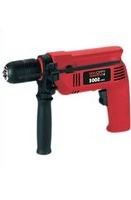
| Model | EURO 2200-1 |
| Supply voltage | 230 V - 50 Hz |
| Motor power | 1.5 kW / 2 HP |
| Rotation speed | 2850 min⁻¹ |
| Operating pressure | 8 bar |
| Tank capacity | 24 L |
| Theoretical suction flow rate | 210 L/min |
| Sound power level | 97 dB(A) |
| Sound pressure level | 87 dB(A) |
| Protection rating | IP 20 |
| Weight | 31 kg |
| Motor oil type | SAE 15W/40 or equivalent |
| Main functions | Compressed air supply for tools, inflation, spray painting |
| Maintenance and cleaning | Oil change every 500 h, air filter cleaning every 300 h, daily condensation drainage |
| Safety | Safety valve, pressure switch, overload protection |
| Included accessories | Wheels, rubber pad, air filter |
| Spare parts and repairability | Parts available via after-sales service; indicate type, article number, and part number |
| Warranty | 2 years |
Frequently Asked Questions - EURO 2200-1 Prowork
User questions about EURO 2200-1 Prowork
0 question about this device. Answer the ones you know or ask your own.
Ask a new question about this device
Download the instructions for your Compressor in PDF format for free! Find your manual EURO 2200-1 - Prowork and take your electronic device back in hand. On this page are published all the documents necessary for the use of your device. EURO 2200-1 by Prowork.
USER MANUAL EURO 2200-1 Prowork
Note the directions for use!
Beware of hot surfaces
natural_image
Simple line drawing of a mechanical component or tool with a base and handle (no text or symbols)General safety instructions
Important! The following basic safety precautions have to be taken when using this compressor in order to guard against the risk of electric shock, Injury and fire. Read and note these instructions before you use the compressor.
- Keep your work area tidy - There is a higher risk of accident in an untidy work area.
- Make allowance for environmental conditions
- Never leave the compressor in the rain. Never use the compressor in damp or wet conditions. Provide good lighting. Never use the compressor near combustible liquids or gases.
- Protect yourself from electric shocks
- Avoid physical contact with earthed parts, e.g. pipes, radiators, cookers, refrigerators.
- Keep children away!
- Do not allow other persons to touch the compressor or its cable. Keep them out of your work area.
- Keep your compressor in a safe place
- When the compressor is not being used it should be kept in a dry, locked room out of the reach of the children.
- Do not overload your compressor
- It is better and safer to work within the quoted power range.
- Wear suitable work clothes
-
Do not wear loose garments or jewellery. There is a risk of them catching on moving parts. Rubber gloves and non-slip shoes are recommended when working outdoors. Put on a hair net if you have long hair.
-
Wear goggles
- Wear a breathing mask when working in dusty conditions.
- Never use the cable for any purpose other than that intended
Never tow the compressor by its cable and never pull the power plug out of the socket by the cable. Protect the cable from heat, oil and sharp edges. - Do not overreach
- Avoid abnormal postures. Stand squarely and keep your balance at all times.
- Look after your compressor - Keep your compressor clean so that it works well and reliably. Follow the maintenance instructions. Check the power plug and cable regularly and have them replaced by a specialist if you discover any damage. Check any extension cables regularly and replace if damaged.
- Pull out the power plug - Whenever the compressor is not being used and before carrying out any maintenance work.
- Do not leave any tools on the compressor
- Before you switch on the compressor, make sure that all wrenches and setting tools have been removed.
- Avoid accidental starts
- Make sure that the switch is turned to OFF before you connect the compressor to the power supply.
- Extension cables for outdoor use
- Use extension cables outdoors only if they are approved and marked accordingly.
- Concentrate at all times
- Watch your work. Be sensible. Do not use the compressor if your mind is not on your work.
- Examine your compressor for signs of damage
- Before you use the compressor again, carefully check its safety devices or any slightly damaged parts to make sure that they are
working properly and as intended. Check moving parts to make sure that they are in good working order and are not jammed or damaged. All parts have to be properly fitted in order to be sure of meeting all the machine's requirements.
Damaged safety devices and parts have to be repaired or replaced by a customer service workshop unless otherwise stated in this manual. Damaged switches have to be replaced by a customer service workshop. Do not use any tools with a switch that cannot be turned on and off.
- Important!
- For your own safety, use only such accessories and auxiliary equipment as are listed in this manual or which are recommended and specified by the manufacturer. There is a high risk of suffering a serious accident if you use tools or accessories which are not listed in this manual or in the catalogue of recommended tools and accessories.
- Have an electrician carry out repairs
- Repairs are to be carried out only by a qualified electrician. If not, the user may suffer serious accidents.
- Connect a dust extraction system
- If there are facilities for connecting a dust extraction system, check that the system is indeed connected and being used.
- Noise
The machine noise may exceed 85 dB(A) at the workplace. In this case, noise protection measures need to be introduced for the user. Keep these safety instructions in a safe place.
Read this manual carefully before putting the compressor into operation!
| Technical data | |
| Power supply 230 V – 50 Hz | |
| Motor rating in kWh.p. 1,5 / 2 | |
| Compressor speed in rpm 2850 | |
| Operating pressure in bar 8 | |
| Pressure vessel volume in litre 24 | |
| Theoretical intake rate in l/min. 210 | |
| Sound power level LWA in dB(A) 97 | |
| Sound pressure level LPA in dB(A) 87 | |
| Protection type IP 20 | |
| Machine weight in kg 31 |
Points to note when setting up the compressor
●Examine the machine for signs of transit damage. Report any damage immediately to the company which delivered the compressor.
●Before you put the compressor into operation, check the oil level in the compressor pump.
●The compressor should be set up near the working consumer
●Avoid long air lines and long supply lines (expansions)
●Make sure the intake air is dry and dust-free.
●Do not set up the compressor in damp or wet rooms.
● The compressor may only be used in suitable rooms (with good ventilation and an ambient temperature from +5° to +40°C). There must be no dust, acids, vapors, explosive gases or inflammable gases in the room.
●The compressor is designed to be used in dry rooms. It is prohibited to use the compressor in areas where work is conducted with sprayed water.
Safety instructions for working with compressed air and paint sprayers
Important! Note the pertinent accident prevent regulations in force in your area!
Compressors and lines reach high temperatures during operation. Avoid contact! Risk of burns!
Gases or vapours drawn in by the compressor have to be kept free of constituents that may cause fire or explosions inside the compressor.
When you disconnect the hose coupling, hold the coupling element in your hand to prevent injury from the whiplashing hose.
Wear goggles when working with the blow-out gun. Injuries may easily result from foreign bodies and blasted parts.
Never point the blow-out gun at other persons and never use it to clean clothes that are still being worn.
Note the safety instructions for paint spraying!
Important! Note the pertinent accident prevent regulations in force in your areal
●Never process paints or solvents with a flash point below 21°C.
- Never heat paints or solvents.
- It is imperative to use filtering equipment (face masks) when processing harmful liquids. Note also the information concerning safety precautions published by the manufacturers of these liquids.
●Smoking is prohibited during the spraying operation and in the work room. Paint vapours are highly flammable.
●Make sure there are no open fires or open lights in the work room. Sparking machines are not to be used.
●Do not keep or consume food and drink in the work room. Paint vapours are harmful.
●The details and designations of the Ordinance on Hazardous Substances, which are displayed on the outer packaging of the processed material, must be observed. Additional protective measures are to be undertaken if
GB
necessary, particularly the wearing of suitable clothing and masks.
●The work room has to be bigger than 30 m^2 and have sufficient ventilation for spraying and drying. Never spray into the wind.
It is always imperative to observe the regulations of your local police authorities when spraying combustible or hazardous substances.
●Never process media such as white petroleum spirit, butyl alcohol and methylene chloride with the PVC pressure hose (reduced life span).
Operation of pressure vessels in accordance with the pertinent pressure vessel regulations
- An operator of a pressure vessel is required to keep the pressure vessel in good working order, to operate it properly, to supervise its use, to carry out essential maintenance and repair work immediately, and to introduce essential safety measures according to requirements.
- The supervisory authorities may order essential safeguards from case to case.
- A pressure vessel may not be operated if it has any defects which constitute a danger to employees or third parties.
- The pressure vessel must be regularly inspected for damage, e.g. rust. If you discover any damage, then please contact the customer service workshop.
Putting the compressor into operation
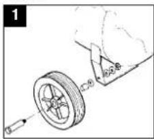
Assembling the wheels (1): Fit the wheels as shown in Figure 1.
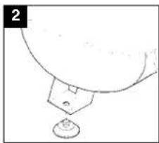
Assembling the rubber buffer Fit the supplied rubber buffer to the support foot as shown in Figure 2.
natural_image
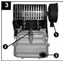
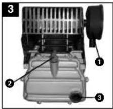
Simple line drawing of a bowl with a small container on top (no text or symbols)Replacing the oil filter and installing the air filter (fig. 3) Use a screwdriver to remove the oil filler plug and insert the supplied stopper (2) in the opening. Important! Check the oil level. Screw the air filter (1) into the hole in the side of the compressor pump.
Connecting to the power supply:
The compressor is equipped with a power cable and an earthing-pin plug for connection to any 230 V \~ 50 Hz earthing-contact socket outlet with a 16 A fuse. Long supply lines, extensions, cable reels and similar cause voltage dips and may prevent the motor from starting. Sluggishness makes starting difficult at low temperatures under freezing point (0°C).
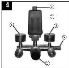
Explanation of the compressed air fittings
1 Pressure switch
2 Safety valve
3 Pressure gauge (to indicate the vessel pressure)
4 Pressure gauge (to indicate the set pressure)
5 Pressure reducing valve (pressure setting)
6 On/Off switch
Maintenance and cleaning
●Condensation water
Let out the condensation water daily by opening the drain valve (bottom of the pressure vessel).
●Safety valve
The safety valve is set to the maximum pressure of the pressure vessel. It is prohibited to adjust the safety valve or to remove its lead seal.
●Regular oil level checks
The level of oil has to be visible in the sight-glass between the red check-point mark and the upper edge of the sight-glass. Changing the oil: Recommended grade SAE 15W/40 or equivalent. The first oil change should be carried out after 100 operating hours. Thereafter you should drain the oil and replace it with new oil at intervals of 500 operating hours.
●Changing the oil
Switch off the motor and pull the power plug out of the socket-outlet. After letting off any air pressure you can remove the oil drain plug from the compressor pump by unscrewing. To prevent the oil escaping out of control, hold a small piece of metal guttering underneath the drain plug to direct the oil into a container. If any oil still remains inside, tilt the compressor a little.
Take the old oil to an official old oil disposal station. When the old oil has run out, screw the oil drain plug/sight-glass back in place.
Use a screwdriver to remove the cap of the oil filler plug and fill in oil until the level of oil in the sight-glass reaches the red mark.
Then put the cap back on the oil filler plug.
1 Filter
2 Oil filler plug
3 Oil drain plug
4 sight-glass
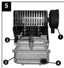
●Cleaning the intake filter
The intake filter prevents dust and dirt being drawn into the machine. This filter has to be cleaned at intervals of no longer than 300 operating hours. A clogged intake filter has a considerable negative effect on the compressor's power.
The filter can be removed as shown in Figure 3. Wash out the filter with petroleum ether and reinsert.
Caution! Wait until the compressor has cooled completely!
Risk of burns!
Setting the pressure switch
The pressure switch is set at the factory.
Switch-on pressure 5 bar Switch-off pressure 8 bar
GB
Possible causes of machine failure
Overloading of the motor and hence triggering of the overload circuit-breaker may result from:
●An excessively high mains voltage
●Excessively high ambient temperatures and an insufficient air supply
●Defective compressor valves or a leaking non-return valve
●A low level of oil, sluggish connecting rod bearings
Leave a.c. motors enough time to cool off before switching on again. Avoid touching hot components and pipe lines.
Ordering replacement parts
Please quote the following data when ordering replacement parts:
●Type of machine
- Article number of the machine
- Identification number of the machine
●Replacement part number of the part required

F
natural_image
Simple line drawing of a bowl with a small container below, no text or symbols presentnatural_image
Simple line drawing of a lamp or lamp with a base and top, no text or symbols presentReplacing the oil filter and installing the air filter(3)
Use a screwdriver to remove the oil filler plug and insert the supplied stopper (2) in the opening.
Important! Check the oil level. Screw the air filter (1) into the hole in the side of the compressor pump.
natural_image
Simple line drawing of a bowl with a small container and a label '2' (no text or symbols on the diagram itself)Conexión eléctrica:
natural_image
Simple line drawing of a bowl with a small container and a handle, no text or symbols presentConexão eléctrica:
natural_image
Simple line drawing of a mechanical component with a base and part, no text or symbols presentElanslutning:
natural_image
Mechanical diagram showing a wheel assembly with a gear and a bracket, no text or symbols presentnatural_image
Simple line drawing of a bowl with a small container below, no text or symbols presentSähköliitäntä:
natural_image
Simple line drawing of a mechanical component or tool with a base and part, no text or symbols present.natural_image
Simple line drawing of a curved object with a small circular base and a small square on top (no text or symbols)Ηλεκτρική σύνδεση:
natural_image
Simple line drawing of a bowl with a small container, no text or symbols presentnatural_image
Simple line drawing of a bowl with a small container, no text or symbols presentEl-tilslutning:
natural_image
Mechanical assembly diagram showing a wheel and attached components (no text or symbols)natural_image
Simple line drawing of a bowl with a small object below, no text or symbols presentzarizeni a casti by mely byt
natural_image
Mechanical diagram showing a wheel assembly with a tool and a bracket, no text or symbols presentnatural_image
Simple line drawing of a bowl with a small container and a label '2' (no text or symbols on the diagram itself)natural_image
Mechanical assembly diagram showing a wheel and attached bracket (no text or symbols)Montaža gumijastega
blažilnika:
natural_image
Simple line drawing of a bowl with a small container, no text or symbols presentElektrični priklop:
natural_image
Technical line drawing of a wheel assembly with a guide rail, no text or symbols presentMontaža gumenog odbojnika: Priloženi gumeni odbojnik se mora montirati na nožicu kao što je prikazano na crtežu 2.

natural_image
Simple line drawing of a bowl with a small object at the bottom (no text or symbols)68
GB EC Declaration of Conformity
The undersigned declares in the name of the company that the product is in compliance with the following guidelines and standards.
The product described in these instructions comes with a 2-year warranty covering defects. This 2-year warranty period begins with the passing of risk or when the customer receives the product. For warranty claims to be accepted, the product has to receive the correct maintenance and be put to the proper use as described in the operating instructions.
Your statutory rights of warranty are naturally unaffected during these 2 years.
This warranty applies in Germany, or in the respective country of the manufacturer's main regional sales partner, as a supplement to local regulations. Please note the details for contacting the customer service center responsible for your region or the service address listed below.
GARANTIBEVIS
» Technical changes subject to change
The reprising or reproduction by any other means, in whole or in part, of documentation and papers accompanying products is permitted only with the express consent of ISC GmbH.
F
THE Cuban International
using international St. Colorado, 152
St. Gallerslaise T62 CH 8404 Wintorthay
CH-0404 Winterthur Tel. (052) 2358787, Fax (052) 2358700
SB Sinball UK Ltd
Unit 5: Microsoft Wharf
Twelve Guests
Twelve Dubys Birkenhead, Mirral
CH 41 1NG
Tel. 0151 6491500, Fax 0151 6491501
TARC EN CIEL ELECTRONIQUE
7A BP 16
F-89000 ST GEORGES/Baulche
Resp. SAV: Oliver DEMEAUX
Alloy Cozins, rub Yawagin Szk. No: 19
Alley Cosine, Iran. Jasethin S.K., No. 15 TB 34843 Maltenc - Istanbul
Tel. 0216 4594865, Fax 0216 4429325
© Agi s.r.o
Stefanikova 10
SK-91101 Trocin
Tel. 32 7445270, Fax 32 7445270
©Turkeslan
Investitions- Baugesellschaft
Christofor Stedanidi
Belinski 102
KZ-486008 st. Chimkent
- MARRIABULOS S.A. Technical & Commercial Company
Technical & Commercial Company
12, Papastrafou & Askipiu Sir GB 18545 Birayu
Tel: 0210 413615
HIS Posters
Altubavskoe shoosa, 24
Akuhyevskoe sn389, Z BUS-127273 Moscow
Tel: 095-5101760
Tel. 095 9033761 (Repair center Moscow)
Tel. 812-2240544 (Repair center St. Petersburg)
17 Didette
©Drdle ©WitMobile Pty. 50
letalo st. 23
LT-02190 Vilnius Tel: 05-0305780 Fax: 05-0305770
©IAS Baltoil
3 Bolton Bouale
Haarlava valid
EE 52102 Tortu
EE-02102 Tartu Tel 07 301 700 Fax 07 301 701
Halei Trading Co. LLC
POB 9282, Naikeel Ed. Deirs. Shop No. 15
UAE-Dubal
Tel. 04 2279554 Fax. 04 2217686
in Alborz Abzar Co. Ltd
No. 111, Bastan Passage, Imam Khomeini Ave
- 111, Bistain P. Avetigo, Imazin T. Roder IP-11146 Teheren
Tel 021 6716072, Fax 021 6727177
Einhol BiH d.o.
Poelowski Center 56
BA-72250 Vitez
Tel 090 717250 Fax 090 717265
(24) Eurasia Industrial and Automotive Supply
- Bessemer Str.
Duncanville
ZA-Vereeniging 1939
Tel 016 455 571 2. Fax 016 455 571 6
(8)Svyaz Prominvest Ltd
207-11. Skariny at
BY-220023 Minsk
Tel 017 2642777, Fax 017 2642591
EH 10/2004
- General safety instructions
- Points to note when setting up the compressor
- Safety instructions for working with compressed air and paint sprayers
- Note the safety instructions for paint spraying!
- GB
- Operation of pressure vessels in accordance with the pertinent pressure vessel regulations
- Putting the compressor into operation
- Connecting to the power supply:
- Explanation of the compressed air fittings
- Maintenance and cleaning
- ●Condensation water
- ●Safety valve
- ●Regular oil level checks
- ●Changing the oil
- Filter
- ●Cleaning the intake filter
- Setting the pressure switch
- Possible causes of machine failure
- Ordering replacement parts
- F
- Replacing the oil filter and installing the air filter(3)
- Conexão eléctrica:
- Elanslutning:
- Sähköliitäntä:
- Ηλεκτρική σύνδεση:
- El-tilslutning:
- Montaža gumijastega
- blažilnika:
- Električni priklop:
- GARANTIBEVIS
- 207-11. Skariny at
Brand : Prowork
Model : EURO 2200-1
Category : Compressor