
WDI101 - Touchscreen HAGER - Free user manual and instructions
Find the device manual for free WDI101 HAGER in PDF.
| Product Type | Touchscreen (touch panel) |
| Brand | Hager |
| Model | WDI101 |
| Dimensions (W x H x D) | 259.4 x 177 x 67.5 mm |
| Screen Size | 10 inches (diagonal) |
| Screen Resolution | 1280 x 800 pixels |
| Screen Type | Capacitive TFT, 16:9 format |
| Brightness | 400 cd/m² |
| Power Supply | Power over Ethernet (PoE+) IEEE 802.3at Class 3 or auxiliary voltage 18-36 V DC (24 V DC recommended) |
| Power Consumption (Operating) | 18.2 W |
| Power Consumption (Standby) | 9.6 W |
| Power Consumption (Off) | 1.4 W |
| Operating System | Windows 10 IoT (pre-installed) |
| Processor | Intel E3930 dual core, 1.8 GHz |
| RAM | 4 GB |
| Internal Storage | 64 GB mSATA SSD |
| Network Connectivity | 2 Ethernet RJ45 ports, 1000 Mbit/s, PoE+ |
| USB Ports | 1 x USB 2.0, 1 x USB 3.0, 1 x Mini-USB 2.0 |
| Other Ports | 1 x RS232 (COM1), 1 x 3.5 mm jack, KNX (optional) |
| Main Functions | Centralized control and visualization of building management, lighting control, blinds, temperature and consumption display, compatibility with domovea server and KNX |
| Mounting | Flush mounting in special box (WDW100/WDW101), horizontal or vertical |
| Operating Temperature | +5 to +35 °C |
| Protection Rating | IP20 (indoor only) |
| Maintenance and Cleaning | Clean with a soft, lint-free cloth, possibly dampened with clean water. Do not use abrasive, acid, or organic solvent products. Use the integrated touch lock before cleaning. |
| Safety | Installation and mounting reserved for qualified electricians. Disconnect power before intervention. Do not use sharp objects on the screen. Class A device. |
| Optional Accessories | Flush-mounted box WDW100 (standard) or WDW101 (flush), 24 V DC DIN rail power supply TGA200, domovea server TJA670/TJA470 |
Frequently Asked Questions - WDI101 HAGER
User questions about WDI101 HAGER
0 question about this device. Answer the ones you know or ask your own.
Ask a new question about this device
Download the instructions for your Touchscreen in PDF format for free! Find your manual WDI101 - HAGER and take your electronic device back in hand. On this page are published all the documents necessary for the use of your device. WDI101 by HAGER.
USER MANUAL WDI101 HAGER
natural_image
Isometric line drawing of a rectangular electronic device with a grid-patterned top panel and mounting ports (no text or symbols)WDI101, WDI161
Panneau tactile Windows
Touch Panel Windows
Touch Panel Windows
(7) Port Gigabit Ethernet RJ45, LAN / PoE+
(11) Ports USB 3.0
(8) Port Gigabit Ethernet RJ45, LAN2


1 Safety instructions.... 14
2 Design and layout of the device 15
3 Function.... 16
4. Operation.... 17
5 Information for electricians .... 20
5.1 Installation and electrical connection.... 20
6 Appendix....24
6.1 Technical data 24
6.2 Troubleshooting.... 24
6.3 Accessories 25
Touch Panel 10" Windows
Order no.: WDI101
Touch Panel 16" Windows
Order no.: WDI161
1 Safety instructions
Electrical equipment may only be installed and assembled by qualified electricians in accordance with the relevant installation standards of the country.
Failure to comply with these instructions may result in damage to the device, fire, or other hazards.
This is equipment of class A. It can cause radio interference in residential areas that the operator must counteract by means of appropriate measures.
When supplying the system with Power over Ethernet (PoE+) the overall performance including all loads connected (e.g. USB devices) may not exceed the power consumption of IEEE 802.3at class 3.
In the case of device variants with PoE+ functions, make sure that no differential ground potentials are used so that this function can be used.
Do not operate the user interface with sharpedged or pointed implements.
Do not use any sharp-edged implements for cleaning. Do not use any acids or organic solvents.
These instructions are an integral component of the product and must be retained by the end user.
2 Design and layout of the device

Figure1: Front view
(1) Touch-sensitive user interface
(2) Microphone
(3) Brightness sensor
(4) Socket for mini USB 2.0
(5) Reset button R for rebooting device
(6) Speaker
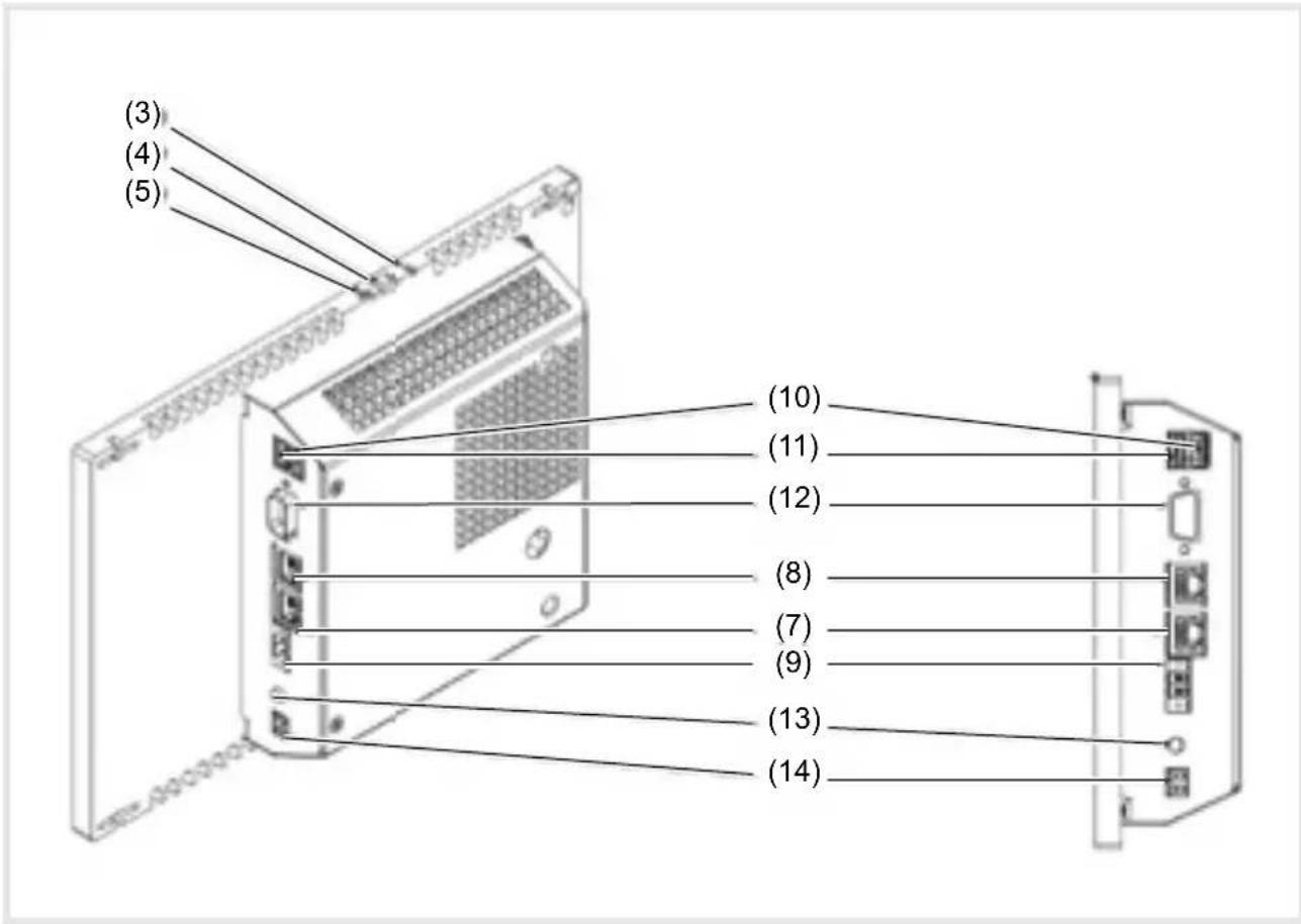
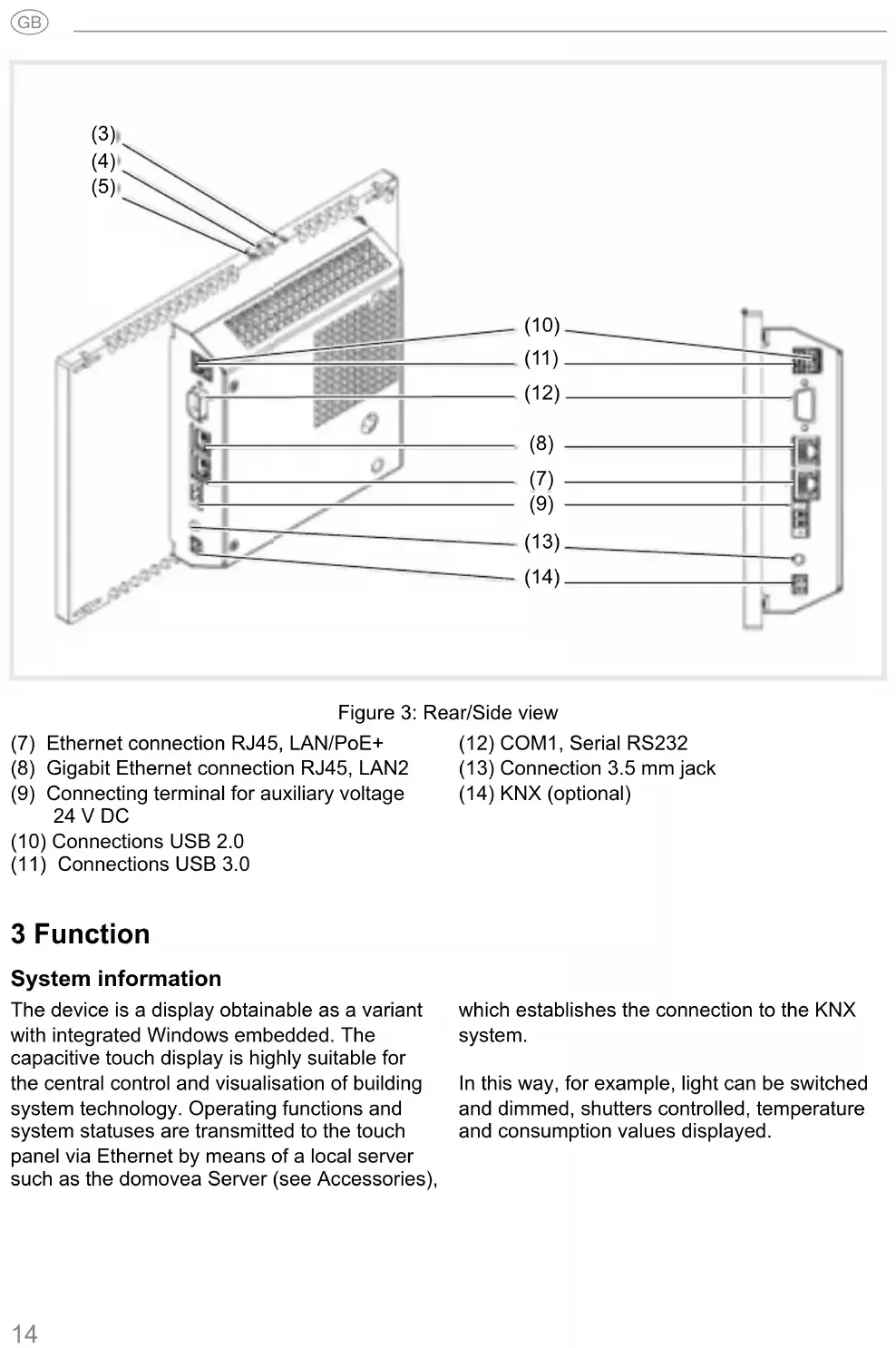
Figure 3: Rear/Side view
(7) Ethernet connection RJ45, LAN/PoE+
(12) COM1, Serial RS232
(8) Gigabit Ethernet connection RJ45, LAN2
(13) Connection 3.5 mm jack
(9) Connecting terminal for auxiliary voltage 24 V DC
(14) KNX (optional)
(10) Connections USB 2.0
(11) Connections USB 3.0
3 Function
System information
The device is a display obtainable as a variant with integrated Windows embedded. The capacitive touch display is highly suitable for the central control and visualisation of building system technology. Operating functions and system statuses are transmitted to the touch panel via Ethernet by means of a local server such as the domovea Server (see Accessories), which establishes the connection to the KNX system.
In this way, for example, light can be switched and dimmed, shutters controlled, temperature and consumption values displayed.
Product characteristics
- Operation directly on the screen with the touch of a finger
- Displaying of configured functions, measured values and data
- USB connections for external data storage media
- Microphone and loudspeaker with echo suppression
- Silent, long-lasting convection cooling without fan
- Disabling function for cleaning the screen by means of Touch Blocker
Correct use
- Only suitable for indoor applications
- The appropriate flush-mounted housing for touch panel (see accessories) must be used for the flush-mounting in hollow walls or solid walls.
- The panel can be mounted in a horizontal or vertical direction.
Please note that the planned visualisation must correspond to the mounting orientation of the touch panel. If, for example, a domovea visualisation is implemented, a horizontal mounting must be provided from a panel size of 10'' or 16''.
Scope of delivery
- Touch panel
- Mini USB/USB type A adapter cable
- Installation material/tool
-
RJ45 connector kit with connector and patch cable
-
Operating system Windows10 ^® embedded
- Touch-Blocker preinstalled on the desktop
- Drivers for the hardware
4. Operation
The screen has a touch-sensitive surface, called touch screen. By touching the user interface with your finger or with a special touch screen pen (not included in scope of delivery) stored actions and functions are activated.
Do not operate the user interface with sharpedged or pointed implements.
If no action is executed on the display within a certain time period, the device returns
automatically to standby display (OFF or screensaver). This time period can be configured individually in the control panel. The display is switched on again by touching the user interface once again.
Loading files from external data storage media
A mini USB socket is available on the upper edge of the display for loading files, e.g. pictures, audios, updates as well as applications (Apps/programs) from an external data storage medium.
If a device is mounted flush with the wall, press left and right evenly against the housing until the locking mechanism is audibly released.
The device is guided out of the wall. The operating elements on the upper edge are accessible.
- Connect the enclosed adapter cable USB/mini USB to the socket (4) if necessary.
■ Connect external data storage medium, such as a USB stick or hard disk, to the adapter cable.
■ Store the data in the device or install applications using the Windows Explorer file manager.
Restarting operating system/launcher
If the device does not react properly during operation, the system should be restarted.
If a device is mounted flush with the wall, press left and right evenly against the housing until the locking mechanism is audibly released.
The device is guided out of the wall. The operating elements on the upper edge are accessible.
- Press the sunken Reset button R using a thin pointed object.
The device will restart automatically. This may take a few seconds. When the home page is displayed, the device is ready for operation again.
Cleaning user interface
A special disabling function, which protects the touch interface against unintended operations for cleaning is preinstalled on the desktop.
■ Start the Touch-Block by a double clicking/touching.

On the display, a countdown takes place for 60 seconds.
- Clean the screen surface with soft, lint-free cloth. Moisten the cleaning cloth slightly with clear water if necessary.
After the countdown has elapsed, the Touch-Block closes automatically. The user interface is no longer blocked.
Do not use any sharp-edged implements for cleaning.
Do not use any aggressive detergents, acids or organic solvents.
Do not allow any moisture to get into the device.
Windows devices
The Windows device are supplied with a preinstalled operating system. The interface corresponds to that of a laptop or PC. Furthermore, the domovea client is preinstalled on
the desktop interface. All standard applications and clients can be installed and used via the interface.
5 Information for electricians
5.1 Installation and electrical connection

DANGER!
Touching live parts in the installation environment can result in an electric shock.
An electric shock can lead to death.
Disconnect the connecting cables before working on the device and cover all live parts in the area!
Preparing installation
As a display and operating panel, the device should be mounted in a place that is easily accessible. The user habits are decisive when determining the installation height. We recommend an installation height from the display/housing centre to the fi nished floor of approx. 1.65 m.
Prevent humidity and excessive dust at the installation location. Do not install the device near heat sources, such as radiators, storage heaters or ovens.
The touch panel must be installed in a separately available flush-mounted housing (see accessories).

CAUTION!
Damage to the device if installed in a warped housing.
The device can be damaged.
When installing the housing in a wall, ensure that the wall opening is big enough and the device can be inserted without tensions.
Information concerning the installation of the fl ush-mounted housing in solid and hollow walls can be referred to in the instructions enclosed.
To avoid EMC interference, do not install network input cables parallel to mains cables.
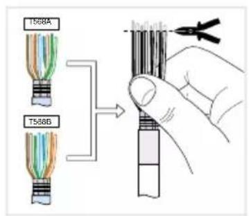
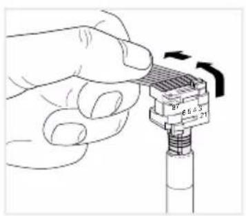
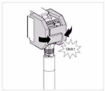
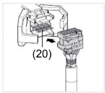
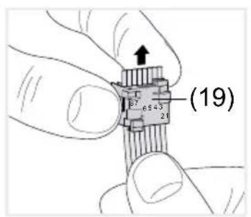
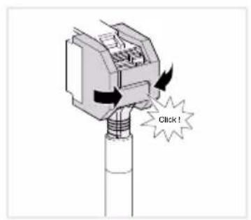
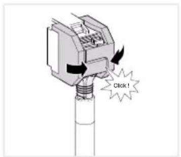
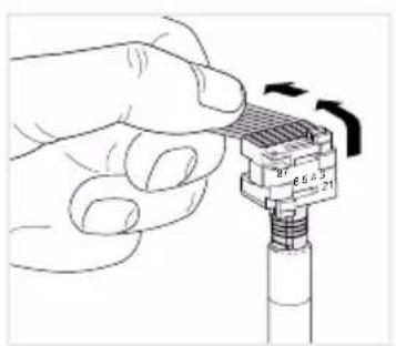
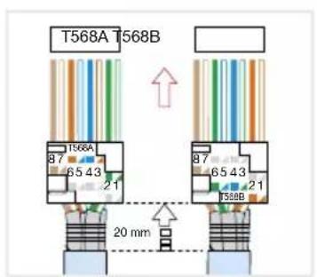
Installing connector (RJ45) on the network cable (fi gure 11)
The flush-mounted housing is installed firmly in the wall. The empty conduit with the network cable is guided through an entry on the housing.
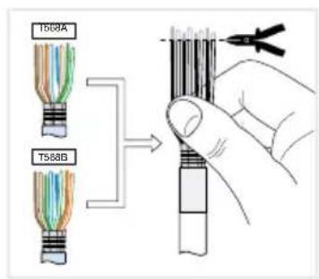
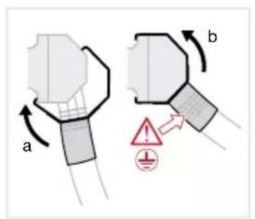
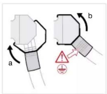
- Insert the network cable through the metal cap's earthing cover of the connector.
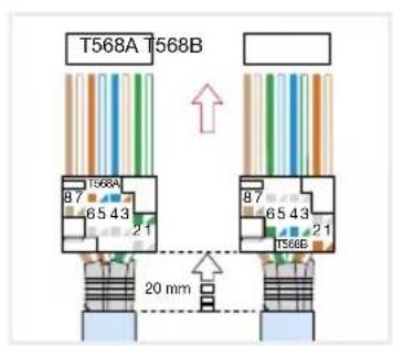
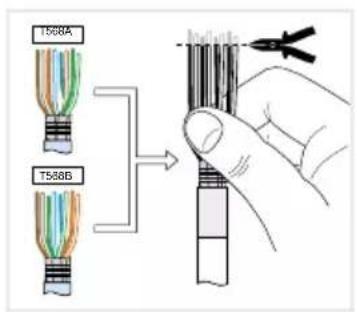
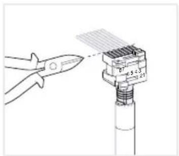
- Strip the Ethernet strands of the network cable, do not remove insulation.
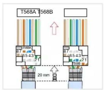
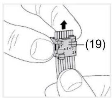
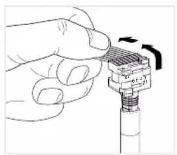
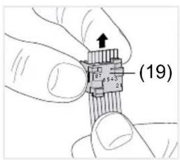
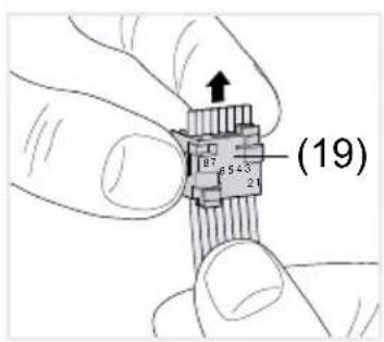
- Insert the strands into the plug-in connector (19) of the connector and bend up 90°. Shorten any protruding strands.
When doing so, it is imperative to observe the colour code EIA/TIA -568 A or B of the
system. This can be found in the documentation of the installed network components and routers. The Ethernet connection has been connected to the device compatible with wired networks in accordance with TIA/EIA-568-A or B
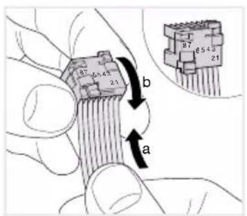
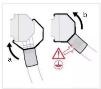
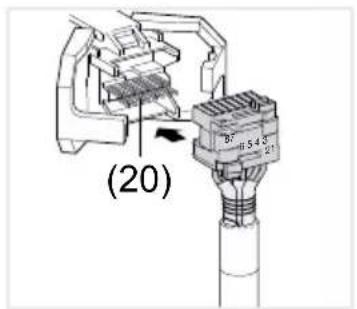
- Insert the plug-in connector into the connector (20) and snap it shut.
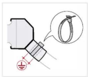
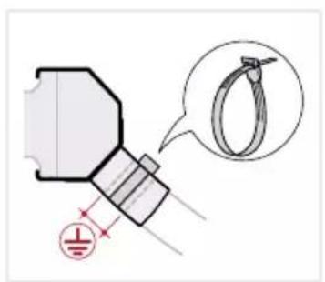
The plug-in connector is locked in place in the connector. - Tighten the enclosed cable tie over the earthing cover.


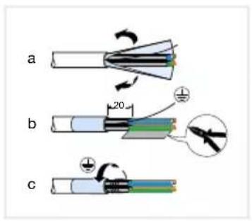
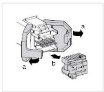


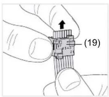


Figure 11: Installing connector on the network cable
Connecting and installing the device
The RJ45 installing connector is mounted on the network cable.
Connect the jack to an RJ45 socket on the touch panel (7/8) using the enclosed, pre-assembled RJ45 patch cable.
If required connect a 24 V DC power supply (see Accessories) using the enclosed terminal (9). Ensure correct polarity (figure 2/3).
- Insert touch panel in the housing (21) in such a way that the mounting plates (22) of the housing are pushed under the frame.
Tighten the four screws and the mounting plates through the frame from above and below using the enclosed Allen key (Figure 12/13). The screws must be countersunk in the frame.
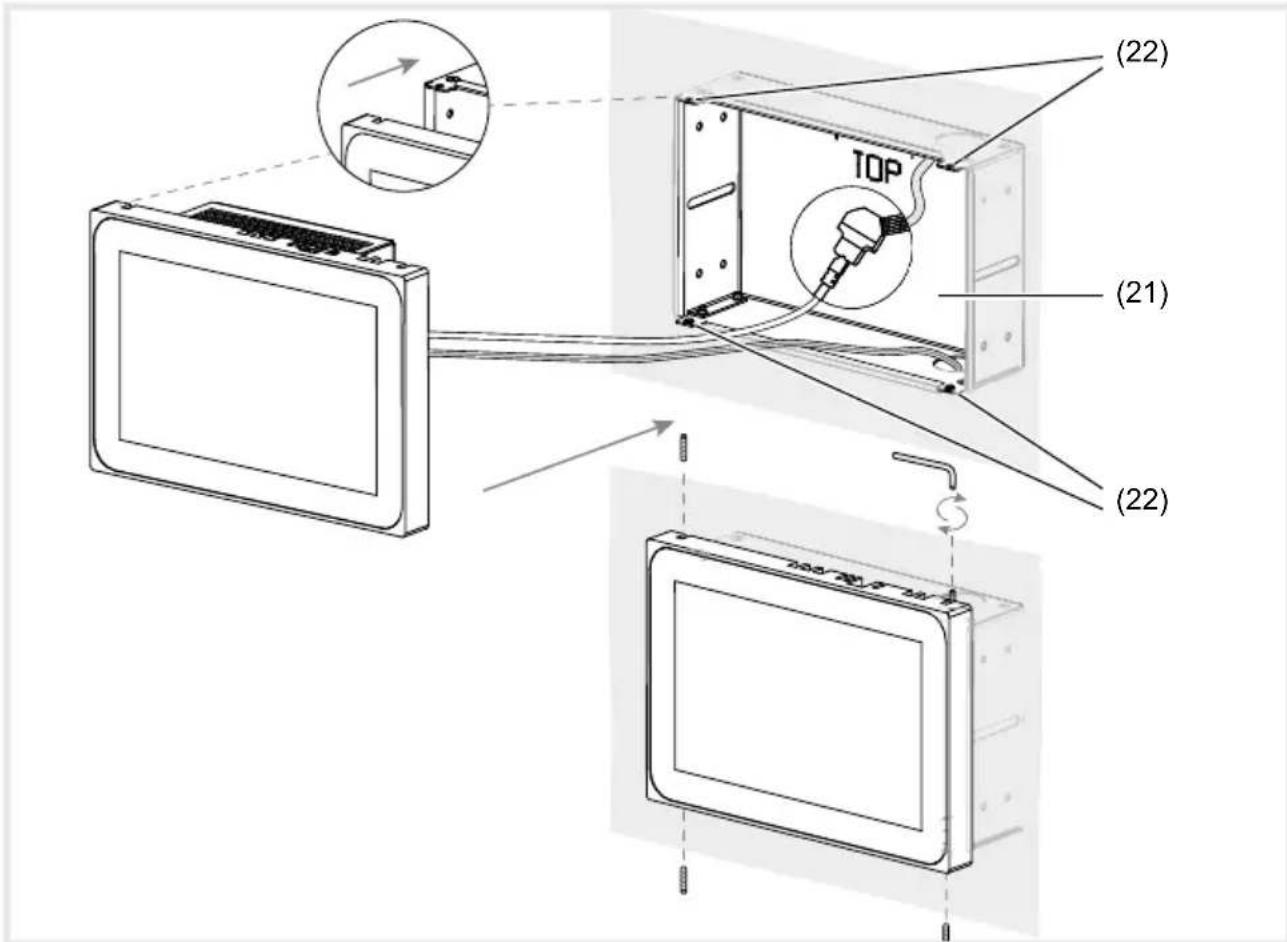
Figure 12 a/b: Installation in the flush-mounted housing
(15) Flush-mounted housing (not included in scope of delivery)
If a device is mounted flush with the wall, guide it into the housing by applying even, slight pressure on the left and right (Figure 13) until the >>Push-to-open<< lock of the housing engages.
When pushing in the touch display into the housing, make sure that the connected cables do not get wedged in.
(16) Mounting brackets
■ Remove the protective foil from the user interface.
■ Switch on auxiliary voltage.
The device charges the operating system/Launcher and displays the desktop interface/home page of the Launcher after a few seconds. Device is ready for operation.
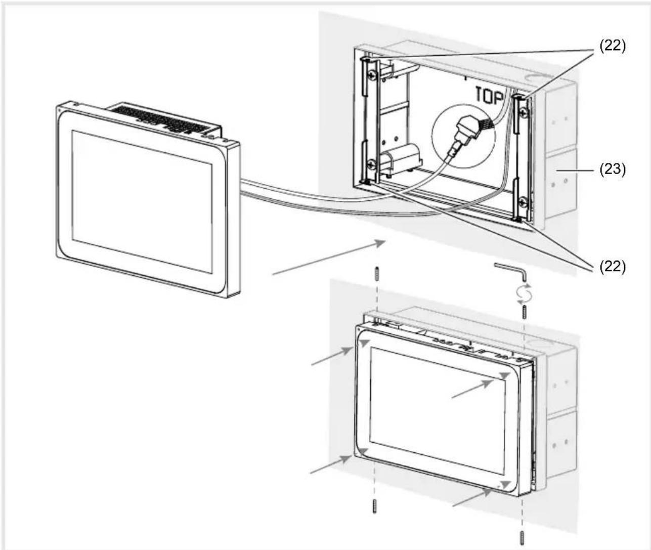
Figure 13 a/b: Flush wall mounting installation in the flush-mounted housing
(17) Flush-mounted housing, flush-to-wall (not within scope of delivery)
Dismantling the device
If a device is mounted flush with the wall, loosen it from its fastening in the flush-mounted housing by applying even, slight pressure and release.
The device will move slowly forward out of the housing.
■ Loosen the screws and remove the device from the housing.
■ Remove connections.
6 Appendix
6.1 Technical data
Capacitive TFT touch display approx. 16:9
USB Output current per socket 500 mA
Storage temperature -20 ... +60 °C
Air humidity 10 ... 90 % at 25 °C,
non-condensing
Degree of protection IP20
Cable cross-section of auxiliary voltage:
- flexible with conductor sleeve max. 0.75 mm ^4
- rigid max. 1.5 mm ^2
| 10'' Windows 16'' Windows | ||
| Resolution 1280 x 800 pixels 1366 x 768 pixels | ||
| Light intensity 400 cd/m2 220 cd/m2 | ||
| Number of USB sockets | 1 x USB 2.0, 1 x USB 3.01x Mini-USB | |
| Data transmission Ethernet | 1000 Mbit/s | |
| Port Ethernet | 2 x RJ45 | |
| Power over Ethernet | PoE+ | |
| Auxiliary voltage | 18 ... 36V DC | |
| Power consumption:- Full load- Idle- Display off- Shut down | 18,2 W9,6 W4,8 W1,4 W | 17 W10 W4,8 W1,4 W |
| Operating system | Windows 10 IoT | |
| Processor | 2x 1,8 GHz Intel E3930 | |
| Main memory | 4 GB RAM64 GB SSD mSATA | |
| Operating temperature | +5 ... +35 °C | |
| Dimensions(W x H x D) | 259.4 x 177 x 67.5 mm | 377.4 x 231.8 x 66.4 mm |
| Assembling heightof frame | 10 mm | 11 mm |
6.2 Troubleshooting
Display surface does not react to operations anymore
Cause: System has been shut down or has crashed.
Press the reset button R (5).
The device will automatically restart.
Operation not possible
Cause: Auxiliary voltage is not present.
Check connection for auxiliary voltage.
Check auxiliary voltage by means of measuring device.
6.3 Accessories
Housing flush-mounted for WDI10x WDW100
Housing flush-mounted for WDI10x, flush-to-wall WDW101
Housing flush-mounted for WDI16x WDW160
Housing flush-mounted for WDI16x, flush-to-wall WDW161
Power supply 24 V DC RMD TGA200
domovea Server TJA670/TJA470
Inhalt


natural_image
Hand holding a connector with a spring, showing pin numbers and rotation arrow (no text or symbols)


natural_image
Hand holding a connector with a spring, showing pin numbers and rotation arrow (no text or symbols)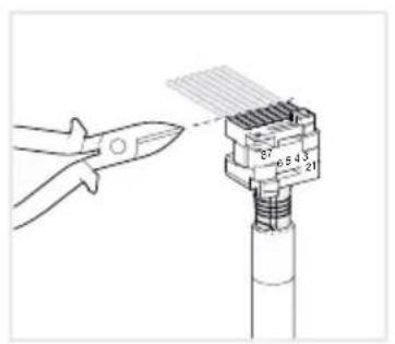


(7) Collegamento Ethernet Gigabit RJ45, LAN/PoE+
(8) Collegamento Ethernet Gigabit RJ45, LAN2


Afb. 11: de stekkerverbinding op de netwerkkabel monteren


- Touch Panel 10" Windows
- Touch Panel 16" Windows
- Safety instructions
- Design and layout of the device
- Function
- System information
- Product characteristics
- Correct use
- Scope of delivery
- Operation
- Loading files from external data storage media
- Restarting operating system/launcher
- Cleaning user interface
- Windows devices
- Information for electricians
- Installation and electrical connection
- DANGER!
- Preparing installation
- CAUTION!
- Installing connector (RJ45) on the network cable (fi gure 11)
- Connecting and installing the device
- Dismantling the device
- Appendix
- Technical data
- Troubleshooting
- Display surface does not react to operations anymore
- Operation not possible
- Accessories
- Inhalt
Brand : HAGER
Model : WDI101
Category : Touchscreen