
S781-22X - Alarm system HAGER - Free user manual and instructions
Find the device manual for free S781-22X HAGER in PDF.
| Product type | Outdoor receiver for alarm system |
| Brand | HAGER |
| Model | S781-22X |
| Power supply | 230 V AC - 50 Hz (16 A) protected and switchable |
| Operating temperature | -20 °C to +70 °C |
| Protection rating | IP55 and IK04 |
| Insulation class | Class 2 |
| Consumption | 17 VA |
| Dimensions (H x W x D) | 150 x 85 x 35 mm |
| Weight | 224 g |
| Installation | Indoor or outdoor |
| Output type | Potential-free dry contact |
| Maximum output power (incandescent) | 1000 W |
| Maximum output power (halogen ELV 12 V) | 1500 W |
| Achievable applications | On/off, timer, impulse, presence simulation, remote control, system status reporting, activation on intrusion |
| Max number of control devices | 15 |
| Maintenance and cleaning | No special maintenance, clean with a dry cloth |
| Safety | Disconnect 230 V mains before any intervention |
| Spare parts and repairability | Not intended for the user, contact HAGER technical support |
| General information | Compliant with R&TTE 1999/5/EC and RE-D 2014/53/EU directives |
Frequently Asked Questions - S781-22X HAGER
User questions about S781-22X HAGER
0 question about this device. Answer the ones you know or ask your own.
Ask a new question about this device
Download the instructions for your Alarm system in PDF format for free! Find your manual S781-22X - HAGER and take your electronic device back in hand. On this page are published all the documents necessary for the use of your device. S781-22X by HAGER.
USER MANUAL S781-22X HAGER
p. 111 External receiver
804638/C

S771-22X : 230 V
S781-22X : 230 V
S791-22X:12-24
natural_image
White rectangular electronic device with three ports and a small inset box (no visible text or symbols)Sommaire Présentat
Présentation......2
Description 2
Applications de base......4
Programmation......18
Essais réels....20
natural_image
Illustration of a smart nightlight with signal waves and a mounted device, no text or symbols presentnatural_image
Illustration of a person standing at a gate connected to a mobile phone with wireless signals, alongside a wall-mounted device (no text or symbols present)Présentation
natural_image
Diagram showing three connected devices: a car, a refrigerator, and a lamp with signal waves (no text or symbols)
flowchart
graph LR
    A["Device"] --> B["Laptop"]
    B --> C["Mobile Device"]
    style B fill:#f9f,stroke:#333
    style C fill:#ccf,stroke:#333


natural_image
Diagram of a device panel with circular components and arrows indicating rotation (no text or symbols)natural_image
Technical line drawing of a device casing with internal components and mounting holes (no text or symbols)Vis de serrage
flowchart
graph TD
    A["Top Panel"] --> B["Device 1"]
    A --> C["Device 2"]
    A --> D["Device 3"]
    A --> E["Device 4"]
    A --> F["Device 5"]
    B --> G["Arrow to Device 1"]
    C --> H["Arrow to Device 2"]
    D --> I["Arrow to Device 3"]
    E --> J["Arrow to Device 4"]
    F --> K["Arrow to Device 5"]
Installation
F
natural_image
Two hand gestures pointing at a white cylindrical device (no text or symbols visible)* Programmation d'usine
Applications avancées
The Ground Truth image displays a single, solid horizontal line. According to Rule 2 (UNDERSCORE & LINE RULES), this is a stylistic or background line, not a placeholder underscore. Therefore, the OCR result must ignore it and output nothing or only meaningful text. The provided OCR content is "____", which consists of four underscores. This is an incorrect interpretation of the line as a placeholder, violating the rule that stylistic lines must be ignored. The OCR has hallucinated underscores where none should exist based on the GT's visual context. Hence, the OCR result is inconsistent with the Ground Truth.
natural_image
Technical line drawing of an open electronic device casing with internal components and labeled ports (no text or symbols present)natural_image
Diagram showing a remote control unit emitting signal waves, a street lamp with a mounted device, and a separate screen (no text or symbols)natural_image
Illustration of a person standing at a gate connected to a mobile phone and wireless signals, with no visible text or symbols.natural_image
Diagram showing a device emitting sound waves next to a device connected to a lamp (no text or symbols present)

natural_image
Technical diagram of an electrical enclosure with internal components and directional arrows indicating flow or movement (no text or symbols)Membrane

natural_image
Technical line drawing of a device rear panel with internal components and no visible text or symbols
natural_image
Diagram of a device panel with circular components and a person silhouette, showing directional arrows (no text or symbols)natural_image
Technical line drawing of a device casing with internal components and mounting holes (no text or symbols)Vite di bloccaggio

natural_image
Technical line drawing of an open electronic device casing with internal components and labeled parts (no text or symbols present)natural_image
Illustration of a smart home security system with wireless signals and a street lamp (no text or symbols)natural_image
Illustration of a person standing at a gate connected to a remote control unit and a wall-mounted air conditioner (no text or symbols present)Beschreibung
Zusatzanwendungen
natural_image
Diagram showing three devices with wireless signals: a mobile phone, a wall-mounted device connected to a lamp (no text or symbols)
natural_image
Diagram of a device panel with circular components and a person silhouette, showing directional arrows (no text or symbols)natural_image
Technical line drawing of a device panel with internal components and mounting holes (no text or symbols)natural_image
Pure electrical circuit lines without any symbolsMontage- punkte

Montage
natural_image
Illustration of a hand interacting with a calculator and a button, next to a sun icon (no text or symbols)natural_image
Technical line drawing of an open electronic device casing with internal components and labeled parts (no text or symbols present)natural_image
Illustration of a smart home security system with a lamp, two speakers, and wireless signals (no text or symbols)natural_image
Diagram showing a device with signal waves connected to a wall-mounted lamp and a separate air conditioner unit (no text or symbols)
flowchart
graph LR
    A["Device 1"] --> B["Device 2"]
    B --> C["Light bulb"]
    C --> D["Device 3"]

natural_image
Diagram of a device panel with circular components and arrows indicating rotation or movement (no text or symbols)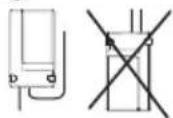
natural_image
Technical line drawing of a device casing with internal components and mounting holes (no text or symbols)natural_image
Pure electrical circuit lines without any symbolsflowchart
graph TD
    A["Outer Box"] --> B["Arrow to Circle"]
    A --> C["Arrow to Square"]
    A --> D["Arrow to Circle"]
    A --> E["Arrow to Square"]
    A --> F["Arrow to Circle"]
    A --> G["Arrow to Square"]
    A --> H["Arrow to Circle"]
    A --> I["Arrow to Square"]
    A --> J["Arrow to Circle"]
    A --> K["Arrow to Square"]
    A --> L["Arrow to Circle"]
    A --> M["Arrow to Square"]
    A --> N["Arrow to Circle"]
    A --> O["Arrow to Square"]
    A --> P["Arrow to Circle"]
    A --> Q["Arrow to Square"]
    A --> R["Arrow to Circle"]
    A --> S["Arrow to Square"]
    A --> T["Arrow to Circle"]
    A --> U["Arrow to Square"]
    A --> V["Arrow to Circle"]
    A --> W["Arrow to Square"]
    A --> X["Arrow to Circle"]
    A --> Y["Arrow to Square"]
    A --> Z["Arrow to Circle"]
Instalación
natural_image
Technical line drawing of two views of an electronic device casing with internal components (no text or symbols)natural_image
Illustration of a hand interacting with a device and a sun icon (no text or symbols)natural_image
Technical line drawing of an open electronic device casing with internal components and labeled parts (no text or symbols present)natural_image
Diagram showing a device emitting sound waves to a street lamp and a separate screen (no text or symbols)natural_image
Diagram showing a car connected to a lamp via wireless signals, with a device labeled 'N L' nearby (no text or symbols on main elements)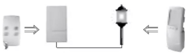
flowchart
graph LR
    A["Remote Device"] --> B["Laptop"]
    B --> C["Mobile Device"]

natural_image
Technical line drawing of a device casing with internal components and mounting holes (no text or symbols)Klemschroeven
natural_image
Pure electrical circuit lines without any symbols
Installatie
natural_image
Illustration of a hand interacting with a calculator and a computer, next to a sun icon (no text or symbols)natural_image
Technical line drawing of an open electronic device showing internal components and mounting points (no text or symbols)Standard applications ......113
Advanced applications......114
Preparation......119
Installation......120
Choosing the best place....120
Standard fixing method....120
Fixing the receiver on a wall box (indoor use only) 120
Connecting the receiver....121
Recognition programming..124
Remote control or keypad (other than a multi-functional mobile keypad) recognition programming..124
Multi-functional mobile keypad recognition programming....125
Control panel recognition programming ....126
Receiver programming......127
Real tests....129
Closing the box .....129
Guarantee of Hager Logisty range products and extension conditions ...130
Technical data....131
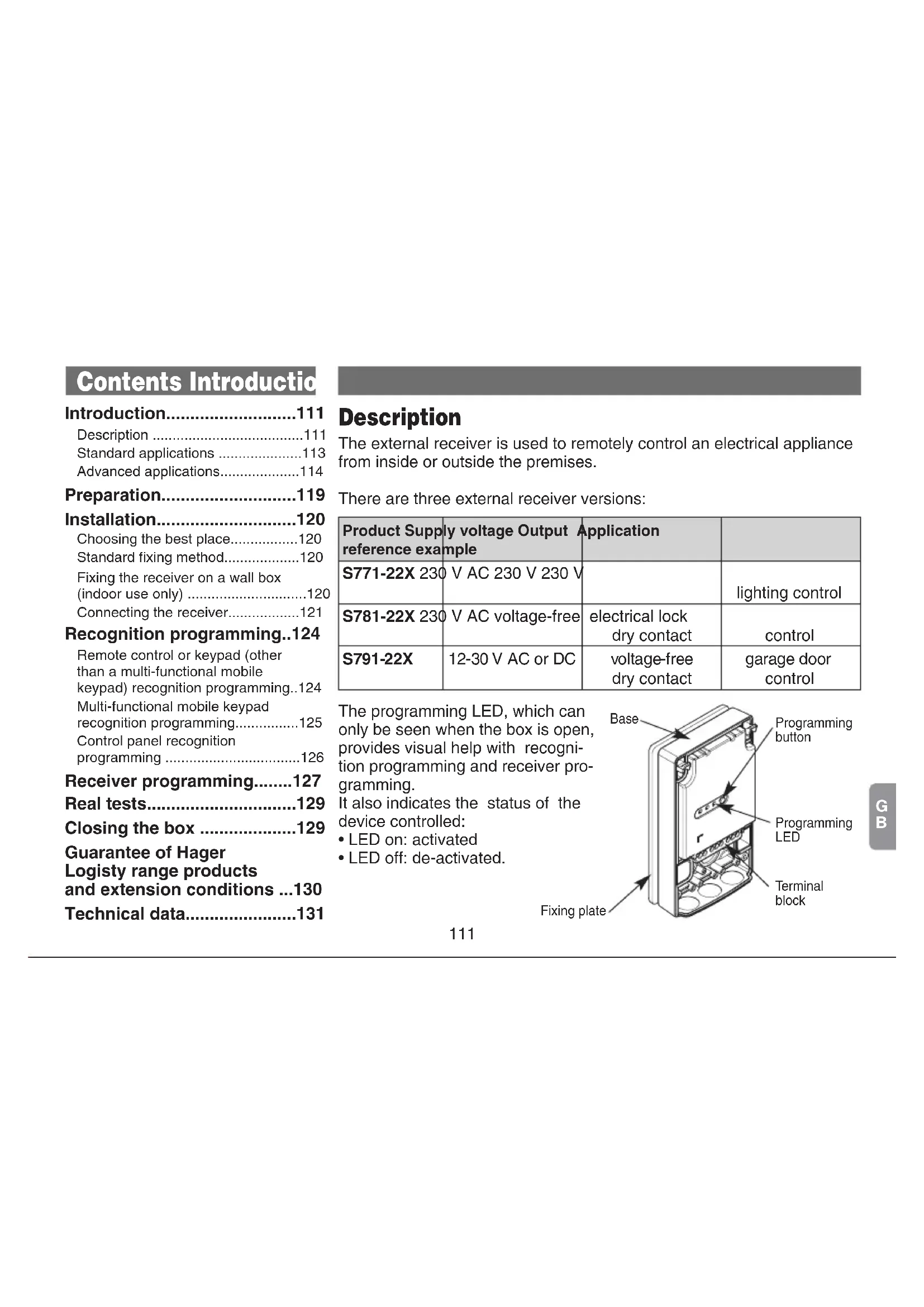
Description
The external receiver is used to remotely control an electrical appliance from inside or outside the premises.
There are three external receiver versions:
| Product Supply reference example | ly voltage Output Application | ||
| S771-22X 230 | V AC 230 V 230 V | lighting control | |
| S781-22X 230 | V AC voltage-free | electrical lock dry contact | control |
| S791-22X | 12-30 V AC or DC | voltage-free dry contact | garage door control |
The programming LED, which can only be seen when the box is open, provides visual help with recognition programming and receiver programming.
It also indicates the status of the device controlled:
- LED on: activated
- LED off: de-activated.

Introduction
There is a choice of control applications as described on the following pages.
Some of these applications may be used simultaneously while others are exclusive applications. The table below illustrates the combinations possible.
| Possible combinations | Exclusive applications | ||
| ON/OFF | Activation on intrusion | Pulse control | System status feedback |
| Timer Remote control | |||
| Presence simulation | |||
Example: an external receiver programmed for ON/OFF control can also be used for Timer or Presence simulation applications.
Introduction
Standard applications
- ON/OFF: for controlling lighting or an electrical appliance using a keypad, multi-functional mobile keypad or remote control with activation and de-activation of the device every time the key is pressed (no activation/deactivation time limit).

natural_image
Illustration of a smart home security system with a lamp, two speakers, and wireless signals (no text or symbols)| Type of remote control | Activating an electrical device | Deactivating an electrical device |
 | Press on a key programmed for: | Press on a key programmed for: |
| • Light ON | • Light OFF | |
| • Light toggle switch | • Light toggle switch | |
| • Relay ON 1, 2, 3 or 4 | • Relay OFF 1, 2, 3 or 4 | |
| • Toggle switch relay 1, 2, 3 or 4 | • Toggle switch relay 1, 2, 3 or 4 | |
 | Press on the Light ON  or Socket ONkey on the Light pageThese keys can also be programmed for the toggle switch function, in which case the same key is used to activate or deactivate the appliance. or Socket ONkey on the Light pageThese keys can also be programmed for the toggle switch function, in which case the same key is used to activate or deactivate the appliance. | Press on the Light OFF or Socket OFFkey on the Light pageThese keys can also be programmed for the toggle switch function, in which case the same key is used to activate or deactivate the appliance. |
Introduction
- Timer: for controlling lighting or an electrical appliance using a keypad, multi-functional mobile keypad or remote control with automatic disarming at the end of the programmed time limit.
| Type of remote control | Start timing Restart timing Stop timing | ||
 | Press on a key programmed for:• Light timer• Timer relay 1• Timer relay 2• Timer relay 3• Timer relay 4 | Press again on a key programmed for:• Light timer• Timer relay 1• Timer relay 2• Timer relay 3• Timer relay 4 | Press on a key programmed for:• Light OFF• Relay OFF 1, 2, 3 or 4• Light toggle switch• Toggle switch relay 1, 2, 3 or 4 |
 | Press on the Light ONorSocket ONkey on the Light pageprogrammedfor Timer mode | Press again on the Light ONorSocket ONkey on the Light pageprogrammedfor Timer mode | Press on the Light OFForSocket OFFkey on the Light page |

The timer is factory-programmed to have a 3-minute time limit. This time limit can be reprogrammed (see "Programming" chapter).
Introduction
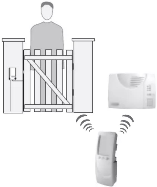
- Pulse: for activating an electrical appliance using a keypad, a multi-functional mobile keypad or a remote control for a time limit of several seconds.
| Type of remote control | Electrical appliance activation/de-activation |
 | Press on the key programmed for Light pulse control:Relay 1 pulse controlRelay 2 pulse controlRelay 3 pulse controlRelay 4 pulse control |
 | Press on one of thekeys on the Opening page(see multi-functional mobile keypad manual) |
Pulse control recognition programming is exclusive (the initial programming has to be deleted, see "Programming" chapter).

The pulse time limit is factory-programmed for 2 sec. This time limit can be reprogrammed (see “Programming” chapter).
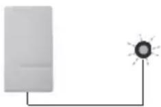
Application example: remote control of an electrical lock or gate.
natural_image
Diagram showing a person standing at a gate connected to a device and a wall-mounted air conditioner, with no visible text or symbols.Introduction
Advanced applications
- Presence simulation: for simulating presence by switching lights or another type of electrical appliance on and off. In this operating mode, the external receiver is controlled by a multi-functional mobile keypad (in Total Armed mode). Please refer to the multi-functional mobile keypad manual for further information.
Example: for controlling lighting via an external receiver in ON/OFF mode using a remote control and simulating presence by switching on the same lighting using the multi-functional mobile keypad.
flowchart
graph LR
    A["Device 1"] --> B["Device 2"]
    B --> C["Light bulb"]
    C --> D["Device 3"]

natural_image
Diagram showing wireless signal transmission between a remote device and two adjacent devices connected by a lamp (no text or symbols)
Application only possible with a multi-functional mobile keypad with activated presence simulation.


This application requires external receiver programming (see "Programming" chapter).
Introduction
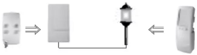
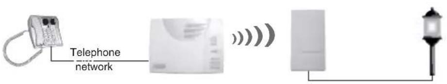
- Remote Control application: control a 230 V electrical appliance when away from home using a fixed or mobile phone via the control panel with telephone dialler.
| Activating an electrical device Deactivating an electrical device | ||
Command to be sent(see Control Panel manual)  | • Light ON | • Light OFF |
| • Relay 1 ON | • Relay 1 OFF | |
| • Relay 2 ON | • Relay 2 OFF | |
| • Relay 3 ON | • Relay 3 OFF | |
| • Relay 4 ON | • Relay 4 OFF | |

This application requires external receiver programming (see "Programming" chapter).
Introduction
- System status feedback: for controlling an electrical appliance or lighting depending on alarm system status, with activation throughout Part Set or Total Arm status operating time and de-activation as soon as the system is disarmed.
| Electrical appliance activation (control panel retransmission) | Electrical appliance de-activation (control panel retransmission) |
| System Part Setting or Total Arming | System Total Disarm |
- Activation on intrusion: for controlling an electrical appliance or lighting when the alarm system is triggered, with activation on intrusion and de-activation after a programmed time limit.
| Electrical appliance activation | Electrical appliance de-activation |
| Alarm system triggering | At the end of the programmed time limitWhen the “Disarm” key is pressed. |


E.g. Flash


These applications require external receiver programming (see “Programming” chapter).
Preparation
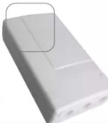
① Lift up the cover.
② Remove the fixing plate from the base by sliding it downwards.
③ Using a sharp object (pen nib, screw, rigid copper wire) punch through the membranes to make holes for the cables.

To guarantee tight fitting:
• make the hole as small as possible (this can be done using a needle),
- if several conductors need to be threaded through the hole these should be bunched together to form a cylindrical cross-section (10 mm maximum ).
④ Remove the fixing plate washer and position it at the top of the plate as shown.
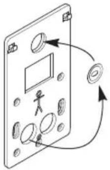
natural_image
Diagram of a device panel with circular components and a person silhouette, showing directional arrows (no text or symbols)⑤ Draw a cable up to where the external receiver is to be located.
⑥ Remove about 40 mm of cable sheath then strip each conductor along 8 to 10 mm.

The maximum conductor diameter must be between 2.5 mm ^2 (or 4 mm ^2 for the earth connection).
Installation
Choosing the best place
The external receiver must be placed with the cables pointing downwards and according to the standard fixing method for outside installation. The external receiver must not be placed:

• directly on a metal wall,
- less than 1 metre away from a water pipe,
- too close to the appliance to be controlled if it is likely to generate interference (neon lighting, etc.).
Standard fixing method
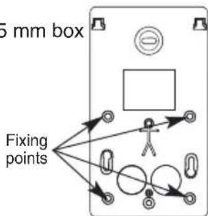
① Put the fixing plate in the place where it is to be installed and mark the position of the fixing points.

natural_image
Diagram of a device panel with labeled components and directional arrows (no readable text or symbols)Example of fixing points
② Drill the holes with a 6 mm ∅ drill bit.
③ Fix the plate using the appropriate wall plugs and screws.
④ Adjust verticality using the washer.
⑤ Hook the base of the external receiver on to the fixing plate and fasten it in position using the screw provided (bag).
Hooks
Risk of electric shock
Switch off the mains 230 V power supply before carrying out work on the electrical system.
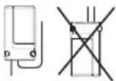
Fixing the receiver on a wall box (for inside installation only)
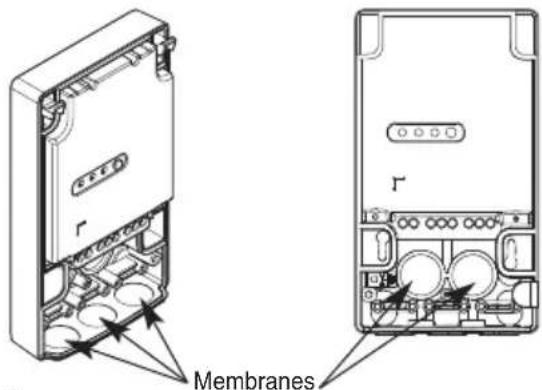
① Thread the cables through the holes in the plate and then through the holes in the base membranes.
② Fix the plate in position using the box screws:
- for a ∅ 60 mm box

- for a ∅ 85 mm box
Installation
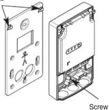
③ Hook the base of the external receiver on to the fixing plate and fix it in place using the screw provided in a bag together with the set of accessories.
Hooks
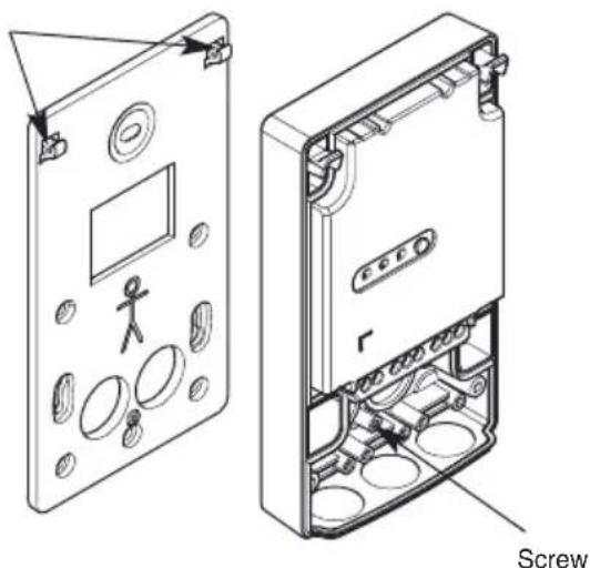
natural_image
Technical line drawing of a device casing with internal components and a screw labeled (no text or symbols beyond label)
In order to save space, the base can be fixed in place without the fixing plate.
In this case, only 2 fixing points for a ∅ 60 mm box are accessible.
Connection
Precautions:
- For controlling class 1 type devices (appliances requiring earthing), make sure the device to be controlled is earthed.
- the mains power supply must be switched off when performing connection operations and applicable electrical standards must be complied with.
- in compliance with electrical standards, the conductors in an electrical installation must be identified by a colour code:
- phase: any colour except light blue, green, yellow or green/yellow,
- neutral: light blue,
- earth: green/yellow
- The maximum conductor diameter for connection to the terminal block is 2.5 ~mm^2 (or 2 × 1.5 ~mm^2 for additional connections) and 2 × 4 ~mm^2 for the earthing connection.

Risk of electric shock
Switch off the mains 230 V power supply before carrying out work on the electrical system.
① Thread the cables through the membranes if this has not already been done.
② Connect the cables as shown in the following diagram:
Installation
S771-22X external receiver (230 V-230V)
Example with connection to external lighting (class 1 type appliance)
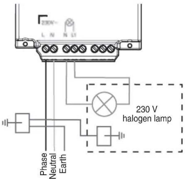
Total maximum output power (depending on type of load):
230 AC halogen lamp 500 W
12 V ELV halogen lamp 1500 W
Incandescent lamp 1500 W
Low consumption bulb 450 W
Fluorescent tube 400 W
S781-22X external receiver (230 V- dry contact)
Example with connection to an electrical lock
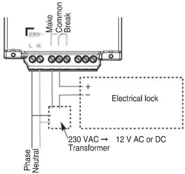
Total maximum output power (depending on type of load):
Incandescent lamp 1000 W
12 V ELV halogen lamp 1500 W

To be fitted on a disconnectable circuit via a 16 A protection device.
Installation
S791-22X external receiver (12-24 V - dry contact)
Example with connection to an automatic gate control system (Normally Open dry contact)
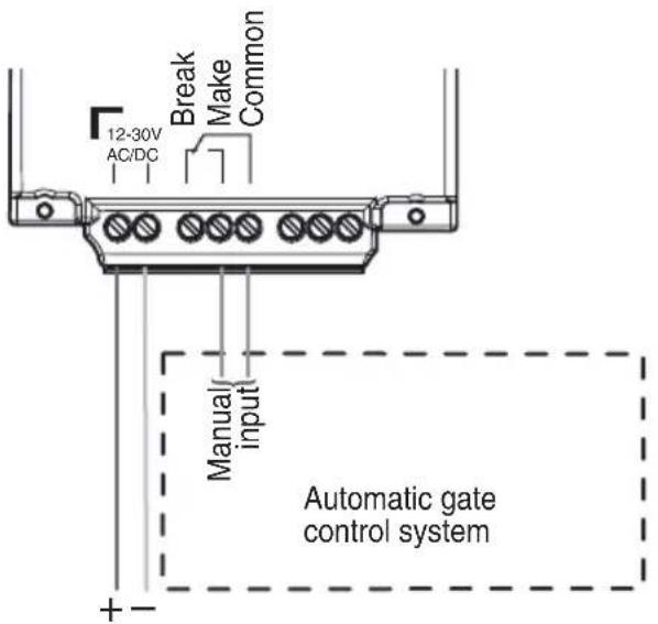
Maximum load:
24 V direct current 1 A
24 V alternating current 2 A
12 V direct current 2 A
12 V alternating current 2 A
③ When using the standard fixing method, hold the cables in place using cable clamps. Fix them in place using the 6 screws provided in the bag along with the set of accessories.

You can now move on to the recognition programming step.
Recognition programming
It is possible to programme the external receiver to be recognised by a maximum of 15 control devices (remote controls or keypads). A control device can control an unlimited number of receivers. Recognition programming must be performed for each external receiver in this case.

Recognition programming must be performed with the device to be controlled de-activated (receiver LED off).
Remote control or keypad (other than a multi-functional mobile keypad) recognition programming
First programme the chosen key for one of the following commands (see keypad or remote control installation guide):
- Light ON,
- Light OFF,
- Relays 1, 2, 3 or 4 ON,
- Relays 1, 2, 3 or 4 OFF
• Light in timer mode, - Relays 1, 2, 3 or 4 in timer mode,
• Light in toggle switch mode, - Relays 1, 2, 3 or 4 in toggle switch mode.
Perform programming as follows:
Press the external receiver programming key (for less than 2 sec.). The programming LED will light up temporarily.
natural_image
Two hand gestures interacting with a calculator and a remote control (no text or symbols visible)Press and hold the programmed key on the remote control or keypad until the external receiver programming LED lights up.

The external receiver confirms programming by its programming LED lighting up for 2 sec.
If you make a programming error, the programming LED will flash quickly. You must carry out the programming sequence again from the start.
Recognition programming
Multi-functional mobile keypad recognition programming
- 1^st possibility for use

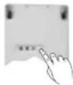
Press the external receiver programming key (for less than 2 sec.).
The programming LED will light up temporarily.
key until the external receiver programming LED lights up.
The external receiver confirms programming by its programming LED lighting up for 2 sec.
If the Light or Socket keys are then re-programmed for Toggle Switch mode, the keypad must be programmed again (see keypad with touch screen manual).
- 2^nd possibility for use
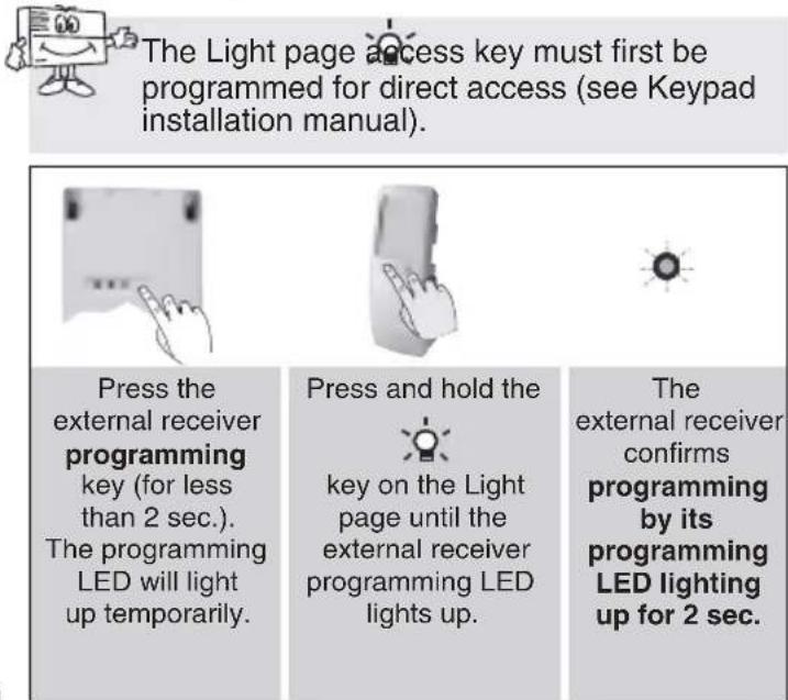
The Light page access key must first be programmed for direct access (see Keypad installation manual).
Press the external receiver programming key (for less than 2 sec.).
The programming LED will light up temporarily.
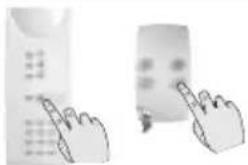
Press and hold the
key on the Light page until the external receiver programming LED lights up.
The external receiver confirms programming by its programming LED lighting up for 2 sec.
If you make a programming error, the programming LED will flash quickly. You must carry out the programming sequence again from the start.
Recognition programming
Control panel recognition programming
The control panel must be in installation mode for programming (see control panel installation manual).

Control panel recognition programming is only required for Remote Control, System Status Feedback and Activation on Intrusion applications. Once recognition programming is complete, it is exclusive. To teach the external receiver to operate with a different control device, the initial recognition programming must be erased as described in the "Return to factory programming" chapter.
Perform programming as follows:

Press the external receiver programming key (for less than 2 sec.).
The programming LED will light up temporarily.

Press and hold The key on the Light page until the external receiver programming LED lights up.

The external receiver confirms programming by its programming LED lighting up for 2 sec.
If you make a programming error, the programming LED will flash quickly. You must carry out the programming sequence again from the start.
Receiver programming
You can programme different operating modes as follows:
- Use the table opposite to choose: - the parameter n^ corresponding to the operating mode to be programmed, - the parameter value corresponding to the feature required.

Programming must be performed with the device to be controlled de-activated (receiver LED off).
| Application/ Parameter setting | Parameter Pa n° value | Parameter Characteristics | |
| ON/OFF always enabled | |||
| Remote control 1 | 1 disabled | d * | |
| 2 light | control operation | ||
| 3 relay | 1 control operation | ||
| 4 relay | 2 control operation | ||
| 5 relay | 3 control operation | ||
| 6 relay | 4 control operation | ||
| Timer | 2 1 90 sec | ||
| 2 3 min * | |||
| 3 5 min | |||
| 4 10 min | |||
| 5 15 min | |||
| 6 30 min | |||
| 7 60 min | |||
* Factory programming
Advanced applications

| Application/ Parameter setting | Parameter Pa n° value | Parameter Ch | Characteristics |
| Pulse | 3 1 | 1 | sec |
| 2 | 2 sec * | ||
| 3 | 3 sec | ||
| 4 | 4 sec | ||
| 5 | 5 sec | ||
| 6 | 6 sec | ||
| 7 | 7 sec | ||
| 8 | 8 sec | ||
| 9 | 9 sec | ||
| Presence simulation | 4 1 dis | sabled * | |
| 2 | enabled | ||
| System status feedback | 5 1 | enabled | |
| Activation on intrusion | 6 1 90 sec | ||
| 2 | |||
| 3 min | |||
| 3 | |||
| 5 min | |||
| 4 10 min | |||
| 5 15 min | |||
| 6 30 min | |||
| Deletion | 9 2 re | turn to factory programming | |
Receiver programming
- Use the programming key to programme the following sequence:

flowchart
graph LR
    A["LED"] --> B["pres s key: once and hold (10 s approx.)"]
    B --> C["configuration sequence"]
    C --> D["1) To start the sequence, press and hold the key until the LED goes out"]
    D --> E["2) Press the key as many times as the parameter number"]
    E --> F["3) Press and hold the key until the LED goes out"]
    F --> G["4) Press the key as many times as the parameter value"]
    G --> H["5) To end the sequence, press and hold the key until the LED goes out"]
    H --> I["LED permanently ON for 2 sec. = configuration correct"]
    I --> J["* Make a note of the chosen parameter number/value"]
• Example of configuring the external receiver in Timer mode:
To change the external receiver configuration to Timer mode for a 15-minute duration, proceed as follows:
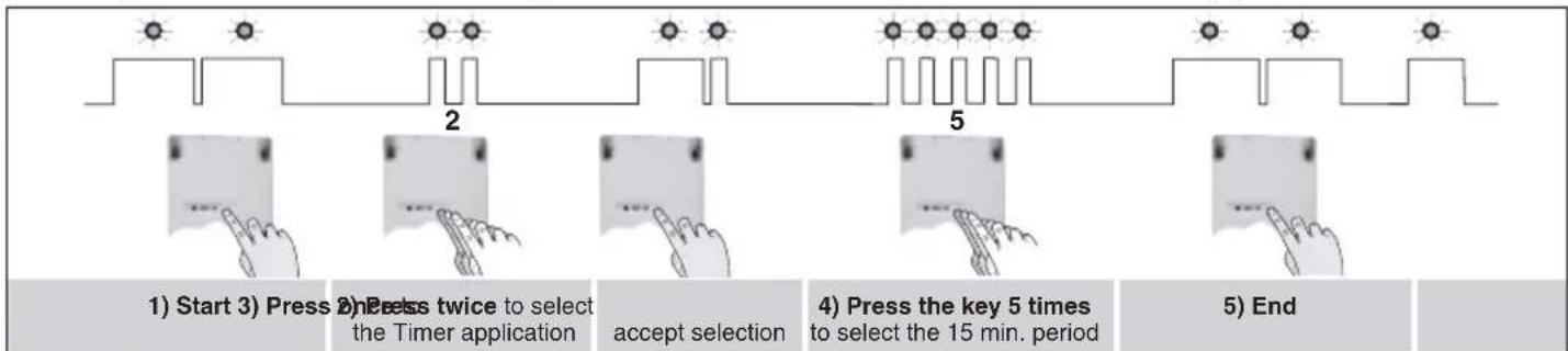
flowchart
graph LR
    A["Start"] --> B["Press twice to select the Timer application"]
    B --> C["accept selection"]
    C --> D["Press key 5 times to select the 15 min. period"]
    D --> E["End"]
If you make a programming error, the programming LED will flash quickly. You must carry out the programming sequence again from the start.
Real tests
Perform real tests to check that external receiver operation corresponds to the selected programming. If a key does not respond, perform separate recognition programming for this key.

Press and hold the key until the device responds.
Closing the box
① Close the box by hooking the cover back on to the base starting from the top.
② Tighten the 2 screws and conceal them using screw covers (provided with the set of accessories).


natural_image
Technical line drawing of an open electronic device casing with internal components and labeled parts (no text or symbols present)Guarantee of Hager Logisty range products and extension condition
Hager Ltd guarantees all its manufactured products for 2 years from the date of registration of the guarantee, or, if not registered by return of the registration card, for 2 years from the date of manufacture
IMPORTANT: Products marketed by Hager Ltd may be granted an extended guarantee of 3 additional years free of charge under the following conditions: in order to be able to benefit from the extended guarantee, within 10 days of the sale the purchaser must return, or otherwise be ineligible, to Hager Ltd, his/her extended guarantee application legibly filled in and duly completed (name and address, retailer's stamp, date of sale, product serial number). Only the date of registration by Hager Ltd shall be valid for assessing compliance with the above-mentioned period.
As regards any purchase of a supplementary product or replacement product within the context of the After-Sales Service, the extended guarantee application corresponding to the product(s) must be returned. Any invoice relating to your products must be retained as this may be required for application of the guarantee. The guarantee gives entitlement to a standard exchange or to repair, at the discretion of Hager Ltd.
The guarantee shall apply only if the product sold is used by the purchaser in the normal manner and under normal conditions, in accordance with the use instructions supplied by Hager Ltd and with its intended purpose.
Any product that has been exchanged becomes the property of Hager Ltd definitively and irrevocably.
Any product exchanged under guarantee benefits from the remaining guarantee term applying to the original product.
The guarantee relates solely to products marketed by Hager Ltd, but does not apply to power sources (lithium cells and batteries) or other consumables.
Certain products or accessories - such as the mobile phone incorporated into GSM diallers, video cameras, motors, etc. (non-exhaustive list) - may not benefit from an extended guarantee. These items are listed by Hager Ltd.
The guarantee does not apply in the event of:
- failure to comply with the installation instructions provided by Hager Ltd,
- abnormal use of the products or use of the products that does not comply with Hager Ltd specifications,
- intervention or conversion of any type whatsoever, apart from any instruction given by Hager Ltd,
• damage by dropping or impact,
- natural disaster, atmospheric phenomenon or vandalism, and also in all cases where an event occurring after the sale, independent of the wishes of Hager Ltd, that is unavoidable and of which Hager Ltd could not reasonably have been held to predict either the occurrence or the effects, would prevent the fulfilment of its essential obligations,
- use of power supplies other than those indicated by Hager Ltd,
- incident arising during carriage,
- negligence or faulty maintenance on the part of the user.
The HAGER guarantee does not affect the legal provisions arising from:
- Articles 1641 et seq. of the Civil Code relating to legal guarantees for concealed defects.
• Article L211-2 of the Consumers' Code.
In the interests of improving its products, Hager Ltd reserves the right to modify them without notice and without prejudice to Article L111-2 of the Consumers' Code.
Technical data
| Technical data External receiver S771-22XS781-22XS791-22X | ||
| Programming LED 1 red programming lighting LED | ||
| Programming key 1 programming pushbutton | ||
| Total maximum output powers S771-22X: S781-22X:• 230 V AC halogen lamp 500 W • incandescent lamp 1000 W• 12 V ELV halogen lamp 1500 W• 12 V ELV halogen lamp 1500 W• low consumption bulb 450 W• fluorescent tube 400 W | ||
| Maximum load | S791-22X: 24 V direct current 1 A 12 V direct current 2 A24 V alternating current 2 A 12 V alternating current 2 A | |
| Applications possible | • ON/OFF• timer• presence simulation (with multi-functional mobile keypad) • remote control• pulse control• system status feedback• activation on intrusion | |
| Power supply | S771-22X/S781-22X:230 V AC - 50 Hz (16 A) with protection and disconnection possibility | S791-22X:12-30 V AC or DC |
| Operating temperature | -20 °C min. / +70 °C max. | |
| Degree of protection | IP55 and IK04 | |
| Insulation class | S771-22X/S781-22X: class 2□ | |
| Consumption | S771-22X/S781-22X: 17 VAS791-22X:12 V direct current: 22 mA - 12 V alternating current: 24 mA - 24 V direct current: 11 mA | |
| Installation | inside or outside | |
| Dimensions (H x W x D) | 150 x 85 x 35 mm | |
| Weight | 224 g | |

Waste processing of electrical and electronic devices at the end of their service life (Applicable in
European Union countries and other European countries with a waste collection system). Used on products or product packaging, this symbol indicates that the product must not be thrown out with household waste. It must be taken to a waste collection point for electrical and electronic product recycling. When you make sure that this product is disposed of in the most appropriate manner, you are helping to protect the environment and human health. If you would like additional information concerning the recycling of this product, please contact your town/city council, nearest waste collection centre or the shop where you bought the product.

DECLARATION OF CONFORMITY
Manufacturer: Hager Security SAS
Address: F-38926 Crolles Cedex - France

09
Product type: External receiver
Trade mark: Hager
We declare under our sole responsibility that the products to which this declaration relates are thus compliant with the essential requirements of the following European Directives:
• R&TTE Directive: 99/5/CE
• Low voltage directive: 2006/95/CE
• Directive ROHS: 2002/95/CE
in compliance with the following harmonised European Standards:
| Products code S771-22X S781-22X S791-22X | |||
| EN 300 220-2 V2.1.2 | X X X | ||
| EN 301 489-1 V1.8.1 X X X | |||
| EN 60950 (2006) | X X X | ||
| EN 60 669-2-1 X X X | |||
| EN 60 730-1 | X X X | ||
| EN 55022 & 55024 (2002) | X X X | ||
| EN 50090-2-2 X X X | |||
These products can be used in all EU, EEA Countries and Switzerland.
Crolles 04/09/09 Signature:
Patrick Bernard
Research & Development Manager
Non-binding document, subject to modification without notice.


:hager
Hager SAS
F-67212 OBERNAI CEDEX
Tél. +333 88 49 50 50
www.hagergroup.net
804638/C


- Sommaire Présentat
- Présentation......2
- Programmation......18
- Essais réels....20
- Présentation
- Installation
- F
- Beschreibung
- Zusatzanwendungen
- Montage
- Instalación
- Installatie
- Description
- Introduction
- Standard applications
- Advanced applications
- Preparation
- To guarantee tight fitting:
- Choosing the best place
- Standard fixing method
- Fixing the receiver on a wall box (for inside installation only)
- Connection
- Precautions:
- S771-22X external receiver (230 V-230V)
- S781-22X external receiver (230 V- dry contact)
- S791-22X external receiver (12-24 V - dry contact)
- Maximum load:
- Recognition programming
- Remote control or keypad (other than a multi-functional mobile keypad) recognition programming
- Multi-functional mobile keypad recognition programming
- - 1st possibility for use
- - 2nd possibility for use
- Control panel recognition programming
- Receiver programming
- Real tests
- Closing the box
- Guarantee of Hager Logisty range products and extension condition
- Waste processing of electrical and electronic devices at the end of their service life (Applicable in
- DECLARATION OF CONFORMITY
- Product type: External receiver
- :hager
Brand : HAGER
Model : S781-22X
Category : Alarm system