
S145-22X - Alarm system HAGER - Free user manual and instructions
Find the device manual for free S145-22X HAGER in PDF.
| Product type | Outdoor passive infrared motion detector |
| Brand | Hager |
| Model | S145-22X |
| Reference | S145-22X |
| Use | Indoor and outdoor |
| Detection principle | Passive infrared, dual beam |
| Coverage | 2 sets of adjustable beams from 2 to 12 m on each side (total range 4 to 24 m) |
| Power supply | Lithium battery BatLi05 3.6 V - 4 Ah |
| Battery life | 5 years (110 max detections/day) |
| Dimensions | 56 x 128 x 235 mm |
| Weight | 596 g |
| Protection rating | IP55 |
| Operating temperature | -20 °C to +50 °C |
| Radio links | TwinBand: 433.050-434.790 MHz and 868-870 MHz |
| Mounting | Wall-mounted |
| Tamper protection | Upon opening |
| Range adjustment | Yes, by vertical sliding of lenses (positions A, B, C, D) |
| Sensitivity adjustment | Yes, via micro-switch (L/M/H) |
| Horizontal angle adjustment | Yes, offset up to 3° |
| Radio delay | 5 s or 120 s depending on setting |
| Maintenance | Regular cleaning of the lens with a soft dry cloth |
| Safety | Tamper protection upon opening, automatic temperature compensation |
Frequently Asked Questions - S145-22X HAGER
User questions about S145-22X HAGER
0 question about this device. Answer the ones you know or ask your own.
Ask a new question about this device
Download the instructions for your Alarm system in PDF format for free! Find your manual S145-22X - HAGER and take your electronic device back in hand. On this page are published all the documents necessary for the use of your device. S145-22X by HAGER.
USER MANUAL S145-22X HAGER
2.1 Opening 2.2 Voeding
2.1 Opening the detector 69
2.2 Power supply 69
-
Programming 70
-
Configuration 71
-
Installation precautions 72
6.Installation. 73
6.1 Testing the radio link 73
6.2 Fixing 73
- Configuration and adjustments
of detection 74
7.1 Range of detection 74
7.2 Horizontal adjustment of the detection angle 76
7.3 Adjustment of the sensitivity.. 77
7.4 Adjustment of the operational options 77
- Operating test 78
8.1 Detection zone test 78
8.2 Real test. 78
9.Maintenance 78
9.1 Fault indication 78
9.2 Changing the battery. 78
9.3 Maintenance 79
- Technical data.. 79
Recommendations
When the product is opened its internal components may be damaged by electrostatic discharge.
The following precautions must therefore be taken during maintenance or repair operations:
- do not touch the electronic components or metal parts of their connections either directly or with ametal tool,
- use non-magnetic tools,
- discharge any static electricity in your clothes by touching a bare metallic surface such as a water pipe or earthed electrical devices before accessing the internal components,
- avoid moving around when accessing the internal components several times during the same operation, to avoid electrostatic charge build-up. Otherwise, apply the precautions above every time you need to access the components.
1. Introduction
The 2 × 12 m external motion detector has been specially designed to detect intruders before they have a chance to break in by monitoring the area outside the protected site.
Because both detection systems operate on either side of the detector and detection can be adjusted to provide narrow 4 to 24m protection (2× 12m on each side), this is the ideal product for protecting a façade. Its immunity to false alarms caused by sunlight or car headlights is backed up by its highly reliable pet-tolerant detection system (both detection beams have to be broken in order to trigger a prealarm or alarm). Its performance is further enhanced by a temperature compensation system that automatically adjusts and increases detection sensitivity when the outside temperature comes close to that of a human being (35^ - 37^)
Back box Detector module

Cover
Locking screwAnti-tamper
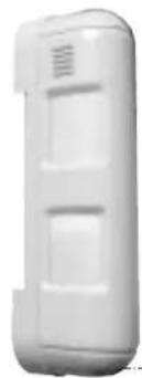
Detection unit with radio box open
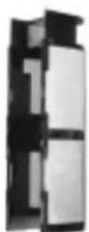
Lens support

Cover
2. Preparation
2.1 Opening 2.2 Power supply
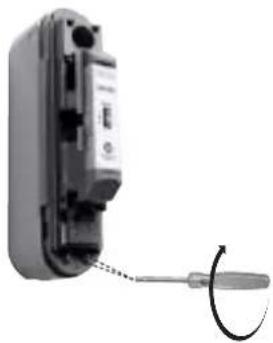
- Remove the cover.
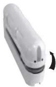
- Remove the back box. 3. Open the radio box.


Connect the battery.
When switched on, the detector runs a self-test. If the self-test is:
- correct, the LED indicator lamp lights up for 2 sec.,
- incorrect, the LED indicator lamp flashes every 5 sec.
3. Programming
CAUTION: during recognition programming, the product to be programmed for use with the control panel does not need to be placed next to it. In fact, we recommend you place the product at a short distance from the control panel (at least 2 m away).
- Change the control panel to installation mode if necessary by pressing the following sequence on the control panel keypad or the hardwired control interface remote keypad:


then:


engineer installer code
- Programme the detector as follows:
CAUTION: the detector number is automatically allocated by the control panel during programming.

- Depends on the type of the control panel
CAUTION: the control panel indicates there is an error by emitting 3 short beeps. When this happens programming should be carried out again.
4. Configuration
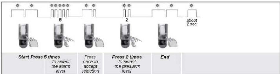
In factory configuration, the movement detector is configured in Discrete pre-alert (for the reactions of the system see the control panel installation guide). It is possible to modify the level of alarm using the following sequence of parameter setting:

Configuration example: setting the detector for an alarm level when a prealarm is triggered: Parameter n° 5, Parameter value 2.
5. Installation precautions
CAUTION: Make sure there is a distance of at least 2 meters between each product, except between two detectors.
The motion detector must be placed:
with an installation height from 0.8 to 1.2m high,
perpendicular to the ground, so that the zone of higher detection is parallel to the ground. If the detector is tilted compared to the ground, the reliability of operation can be reduced,

- so that the detection beams are parallel to the wall.

The motion detector must not be placed:
- in an area likely to receive direct sunlight or a very powerful light source,

- facing moving objects (branches, bushes, flags, etc),
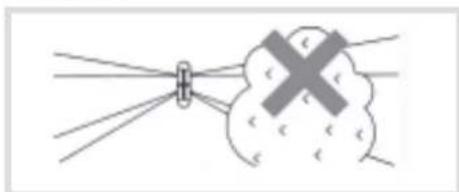
away from the wall (must not be used for infrared barrier type perimeter protection),
- directly on to a metal wall or close to sources of interference (electricity meters, etc.) or ventilation such as air-conditioning grilles.
6. Installation
6.1 Testing the radio link 6.2 Fixing
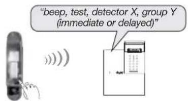
- Before fixing the detector, place them close to the fixing point and check the radio link with the control panel. If the link with the control panel is correct, the control panel issues a voice message identifying the detector activated.
- Press (>5 sec.) the "test" button on the detector, the control panel issues the following voice message: "beep, test, detector X (customised message), group Y (immediate or delayed)".
- Drill the fixing holes using the drilling template provided in the packing box.

- To fix the back box on the wall using wall plugs and suitable screws (not provided).
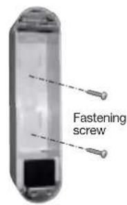

- Position the detection module on the back box then tighten the screws.
7. Configuration and adjustments of detection
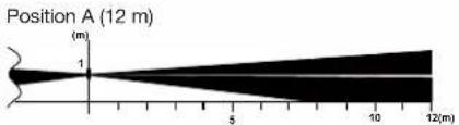
7.1 Range of detection
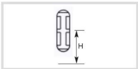
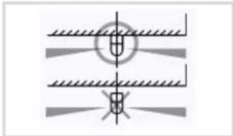
The higher beam remains always parallel on the ground. Being given that the beams (higher and lower) must be broken simultaneously to set off an alarm, the range of the detector is limited to the range of the lower beam.

Detection: the lower and higher beams are broken
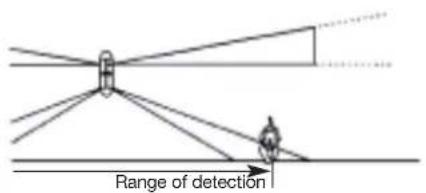
No detection: only the lower beam is broken No detection: only the higher beam is broken

The right-hand and left-hand detection beams must be adjusted separately according to the detection environment.


The lower beam is adjusted according to the position of the lens as the figures show it below. To adjust the range of detection:
- Separate the support from lens and the cover as indicated.
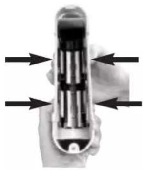
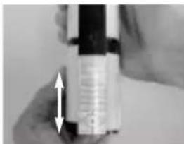
- Adjust the detection ranges separately by sliding the lenses vertically to marks A, B, C or D.
Height of installation 1 m
| Position | Standard range(m) | Maximum range* (m) |
| A 12 | 10 - 15 | |
| B 8 | 6 - 10 | |
| C 5 | 4 - 6 | |
| D 2 | 1.5 - 8 |
- The maximum range can vary from the standard values according to the environmental conditions.
CAUTION: the lenses must not be positioned crossways in the lens support.


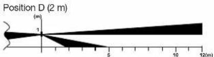
- If you wish to adjust the detection angle horizontally, go to the next paragraph. Otherwise, put the lens support back in place. Check that it is held firmly on either side by the six cover slots.
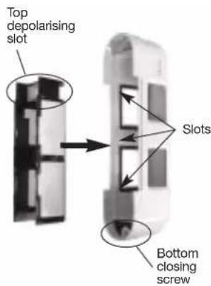
7.2 Horizontal adjustment of the detection angle
If there is an obstacle in the way of the detection beams, they can be horizontally offset by 3^
CAUTION: because an alarm is triggered when both the upper and lower beams are broken at the same time, the detection angle of both must be horizontally adjusted. Set the sensitivity setting to H in this case (see Adjustment of the sensitivity).

To adjust the detection angle:
- Separate the support from lens and the cover (see 1. Range of detection).
- Adjust the detection angles separately by sliding the lenses horizontally.
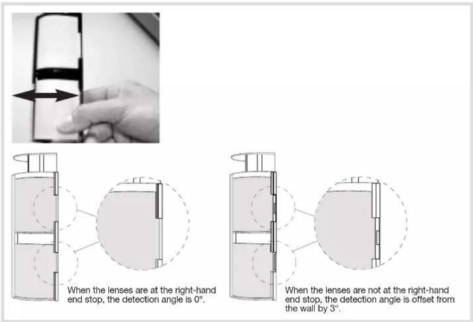
- Position the lens support back in place (see 3. Range of detection).
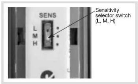
7.3 Adjustment of the sensitivity 7.4 Adjustment of the operational
This adjustment makes it possible to adjust the sensitivity level of the detector.
For environmental conditions:
- difficult (wind, bad weather...), decrease the sensitivity (position L),
- standard sensitivity leave the switch in position M.
When the detection angle has been adjusted by 3^ (see Horizontal adjustment of the detection angle), or if maximum sensitivity is required at the detection limit (at a distance of around 12m ), set sensitivity to H.
The adjustment of the options is done by 3 DIP switches located inside the detector.
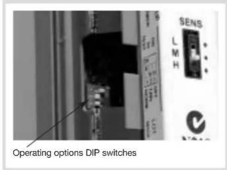
CAUTION: if you position dip-switch 2 or dip-switch 3 on ON, this will lower the battery life.
| ON 1 2 3 | Detector in TEST mode, LED lights during each detection. |
| ON 1 2 3 | Detector in NORMAL mode, LED remains off (except if the DIP switch n° 3 is on ON). The period between radio transmissions depends on the position of DIP switch n° 2. |
| ON 1 2 3 | 5 sec. battery saving timer radio transmissions are limited to a 5 second timer interval even if multiple detections occur. |
| ON 1 2 3 | 120 sec. battery saving timer Radio transmissions are limited to a 120 second timer interval even if multiple detections occur. Position recommended in the event of frequent passage inside the zone of detection. |
| ON 1 2 3 | Selecting LED indicator status The LEDs light up on detection in both test and normal operating mode. |
| ON 1 2 3 | Selecting LED indicator status The LEDs light up on detection in test mode only. Position recommended in the event of frequent passage inside the zone of detection. |
8. Operating test
8.1 Detection zone test
- Put DIP switch 1 in the ON position.
- Close the detector cover.
- Switch the control panel to test mode:

engineer installer code
- Check the area of detection using the indicator LED and adjust the detector if need be. With each detection the control panel issues the voice message "Beep, intrusion or Beep prealarm, detector X".
- Switch the control panel back to installation mode, press:

engineer installer code
- Reopen the cover, to put DIP switch 1 to OFF.
Close the detector cover and tighten the locking screw.
8.2 Real test
- Switch the control panel to user mode:

- Put your control panel in Total Arm mode.
- Wait for the exit time delay.
- Cross over the protected area and check that the control panel responds (see your control panel's installation manual).
9. Maintenance
9.1 Fault indication
The control panel takes battery faults, anti-tamper faults and radio faults on the detector into account.
Battery fault
Following a system command, the control panel issues the following voice message: "beep, fault, battery, detector X ".
Anti-tamper fault
Following a system command, the control panel issues the following voice message: "beep, fault, anti-tamper, detector X^
Radio fault
Following a system command, the control panel issues the following voice message: "beep, fault, radio, detector X".
9.2 Changing the battery
CAUTION: the detector's configuration is saved when the battery is changed.
- Switch the control panel to installation mode and ask the master user to press:

then press:

- Open the case of the detector (see § Opening the detector).
- Replace the used lithium battery.
CAUTION: the test button makes it possible to check if the battery is OK. The indicator on the radio board lights red when the button is pressed.
- Switch the control panel back to user mode, press:

engineer
staller code


- Perform another operating test (see § Operating test).
It is essential to replace the lithium battery with the same type of battery (3.6 V BatLi05).
Please dispose of the old battery in a battery recycling bin.

9.3 Maintenance
- Check and clean the product regularly.
- Any form of dirt or substance that may be deposited on the surface of the lens can or modify the detection performance.
Example:
- the presence of frost on the lens may even make the detector inoperative,
-
a detector with a lens fouled by plant deposits or pollution may cause a false or delayed activation.
-
Technical data
| Specifications | Outdoor motion detector 2 x 12 m S145-22X |
| Detection | infrared |
| Coverage | 2 x 2 to 12 m adjustable beam assemblies |
| Use | inside/outside |
| Power supply | 3.6 V - 4 Ah BatLi05 lithium battery |
| Battery life | 5 years in normal conditions of use (110 detections max./day) |
| Radio links | TwinBarfd • 433,050 - 434,790 MHz, 10 mW max, Duty cycle: 10% • 868 - 870 MHz, 25 mW max, Duty cycle: 0,1% |
| Fixing methods | wall |
| Operating temperature | - 20°C a + 50°C |
| Degrees of mechanical protection | IP 55 |
| Anti-tamper protection | against opening |
| Dimensions L x W x H | 56 x 128 x 235 mm |
| Weight | 596 g |
FR
Hager Security SAS hereby declares that the radioelectric equipment, reference S145-22X, complies with the requirements of the following 2014/53/EU RE-D directive.
The full text of the EU Declaration of Conformity is available at the address: www.hager.com
Non-contractual document, may be modified without prior notice.
:hager
Hager SAS
F-67212 OBERNAI CEDEX
TéI. +333 88 49 50 50

- Opening 2.2 Voeding
- Recommendations
- Introduction
- Preparation
- Opening 2.2 Power supply
- Programming
- Configuration
- Installation precautions
- Installation
- Testing the radio link 6.2 Fixing
- Configuration and adjustments of detection
- Range of detection
- Horizontal adjustment of the detection angle
- Adjustment of the sensitivity 7.4 Adjustment of the operational
- Operating test
- Detection zone test
- Real test
- Maintenance
- Fault indication
- Battery fault
- Anti-tamper fault
- Radio fault
- Changing the battery
- Maintenance
- FR
- :hager
Brand : HAGER
Model : S145-22X
Category : Alarm system