McGuard UP - Motion detector GROTHE - Free user manual and instructions
Find the device manual for free McGuard UP GROTHE in PDF.

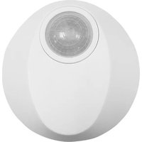
| Product type | Passive infrared (PIR) motion detector with acoustic control |
| Brand | GROTHE |
| Model | McGuard UP |
| Dimensions (decorative frame) | 50 x 50 mm |
| Recessed depth | 40 mm (standard switch box) |
| Weight | Approx. 100 g |
| Power supply | 220-240 V~, 50/60 Hz |
| Power consumption | Approx. 0.5 W |
| Maximum load (incandescent lamps) | 2000 W |
| Maximum load (LED) | 400 W |
| Detection angle | 180° |
| Detection range (front) | Up to 5 m (at 1.2 m height) |
| Detection range (side) | Up to 6 m (at 1.2 m height) |
| Recommended mounting height | 0.8 to 1.5 m |
| Brightness threshold adjustment (LUX) | Approx. 10 lux to 100% (or memory) |
| Time delay adjustment (TIME) | 10 s to 30 min, test (1 s) and impulse (staircase) |
| Microphone sensitivity adjustment (MIC) | + (max.) / - (disabled) |
| Operating modes | Manual ON, AUTO, Manual OFF |
| Protection type | IP40 |
| Operating temperature | 0°C to +45°C |
| Cleaning | Dry cloth only |
| Warranty | 24 months |
Frequently Asked Questions - McGuard UP GROTHE
User questions about McGuard UP GROTHE
0 question about this device. Answer the ones you know or ask your own.
Ask a new question about this device
Download the instructions for your Motion detector in PDF format for free! Find your manual McGuard UP - GROTHE and take your electronic device back in hand. On this page are published all the documents necessary for the use of your device. McGuard UP by GROTHE.
USER MANUAL McGuard UP GROTHE
→ Mortgage Addressing
Demontage Anweisung
10 x (1 x 58W); 5 x (2 x 58W)
LED Lamp: Max. 400W
Energy Saving Lamp : Max. 600VA / 400W
(incl. CFL and PL Lampe)
Power Approx. 0.5W
consumption:
Detection 180° up to 8m forward und 6m each sideward
Range at hight of 1.2m
LUX Adjustable from approx. 10Lux to (∞) and ※
(earning range: 10Lux - 2000Lux)
Auto Off Time Adjustable from approx. 10Sek to 30Min, and
1
Mic. Sensitivity + (max.) / - (off)
TECHNICAL SPECIFICATIONS
Operation Mode Manual ON / AUTO / Manual OFF
Environmental Protection
IP40

Installation and assembly of electrical equipment
must be carried out by qualified electricians.
Contact a qualified electrician in the event of fault
or break down.
CAUTION!
- A circuit breaker (250VAC, 10A) type C according to EN90898-1 of load shell bar
installed in the fixed wiring for protection. Do not mount on conductive surface.
- Do not open the enclosure frequently
- Turn oil power when charge the light sources
-High is-nash trained would be caused when to the use of carbon bonds learned which
and, which is the life, possibly.
1 PACKAGE CONTENTS
| Pattern | |||
| Item | Detector | Lens shield label | Manual |
| Quantity | 1 | 1 | 1 |
2 PRODUCT DESCRIPTION
Der Mc Guard is en indoor wall switch presence detector, and is ideally to be located in small-sealed stores or factories, offices, homes, at the places such as corridors, staircase, archive rooms, collars, rest rooms, play rooms, garages, etc.
2.1 Features
- The stylish cosmetic design of integrating lens with front housing and
invisible knobs for restricting the liberty of unauthorized operation
- Superorors pattern and well distributed as well as concentration detecting beams provide high sensitivity.
- In adapting to PIP, running the detector
- In decision to FIR sensing, the detector can be properly triggered by the sound too.
- Excepting the provided Lux values, the ambient light level can be read-in
as the Lux value for more flexible application.
- Three practical operation modes (Manual ON / AUTO / Manual OFF)
available for user's flexible application.
- The connected lighting can be manually switched off/on by connecting a push button switch to the detector.
- The decorative frame of 50 x 50
- The doctor's name of 30 x 30 in the most European standards will switches.
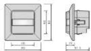
2.2 Dimension
80 x 80 x 51.5mm (See FIG. 1)
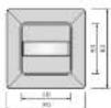

FIG.1
3 INSTALLATION AND WIRING
Please disconnect power completely and read the
entire instruction manual carefully before installation.
3.1 Select a proper location
3.1.1 Detection coverage
It is recommended to install at the height of 0.8m - 1.5m. The forward detection distance can reach up to 8m and 180 detection angle (See FIG.2).
Top view
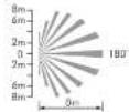
Side view
Top view
Side view

Bik 2
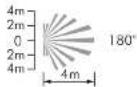
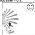
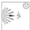
3.1.2 Pay attention to the waking direction in the test proceeding. It is more expensive to move over the directions and less expensive to
sensitive to movement across the detector and less sensitive to movement directly toward detection which will reduce the detection
coverage (See FIG.3)
Bikl 9
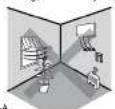
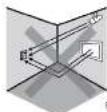
3.1.3 Helpful tips for installation
Since the detector is in response to temperature change, the
following conditions should be avoided (See FIG.4-A & FIG.4-B): Avoid aiming the detector toward the objects which move over
- Avoid aiming the detector toward the objects which may be swayed in the wind, such as curtain, tall alarms, miniature garden etc.
- Avoid aiming the detector toward the objects whose surfaces are highly
reflective, such as mirror, monitor, etc.
- Avoid mounting the detector near heat sources, such as heating vents, air
conditioning, vents as
3.2 Function
3.2.1 Ambient light appraisal
According to the chargeable ambient light level, detector can postpone delay time of switching light on and off to avoid unnecessarily switching due to rapid ambient light change:
Ambient light level changes from bright to dark:
If the ambient light level keeps be lower than the preset Lux value for
10sec. The light will be automatically switched on after 10sec. (LED will be on 15sec for indication).
Ambient light level ch
Ambient light level changes from dark to bright. If the ambient light level continuously exceeds the
If this element is high, level continuously exceeds this section on Lox value for 5min. There are different reactions according to the time setting value.
Time setting ≥ 5min the final will be automatically switched off after 5min .
Time setting < 5min, the light will be automatically switched off when the set
time reached if no movement is detected during the 5min. But if there is
movement detected within the 5min, the time will be reset upon detection and until 5min later, the light is switched off.
3.2.2 Manual on / off switching by using push button to activate R terminal
An additional push buling can be connected between terminal B sent 1
for manual on / off operation (case 1: on → off; case 2: off → on). While
pressing push button (≤1sec).
Case 1: Manual off switching (Lux settings is invalid):
Under the light on status, the light can be manually switched off by short pressing (1sec) the push button. During this operation mode, once the detector is triggered by movement, the light keeps off within the set switch off delay time. Until there is no movement detected and the pre-set switch off delay time has reached, the detector resumes to work according to the previous operation mode set by knobs or IR. To press the push button
(s1sec) during the light manual off period will activate the manual light on function (working as the Case 2).
Case 2: Manual on switching (Lux settings is invalid): Under the light off status, the light can be manually switched on by short prassing (.1sec) the push button. During this operation mode, once the detector is triggered by movement, the light keeps on within the pre-set switch off delay time. Until there is no movement detected and the pre-set switch off delay time has been checked, the detector returns to work according to the controller.
The manual, the manual machine is work according to the previous operation mode set by knobs or IR. To press the push button (≤1sec) during the light manual on period will activate the manual light off function (working as the Case 1).
3.2.3 Auto sensitivity adjustment function To raise the sensitivity of detector after load is switched on can reduce the possibility of false-off problem. When the load is on, the sensitivity of detector will be raised automatically. When the load is off, the sensitivity of detector will return to normal standby condition.
3.2.4 Acoustic control function
By setting the Mic knob to "+" position, this function is enabled. This function is only available when detector works in auto mode and the detector is activated by movement at first, then the acoustic sensor control function is workable. Once the detector is firstly triggered by movement to turn on the load, then within 2sec, the acoustic sensor is used as an operation based on a fixed mechanism with the play-off
Extrusive sensor to be activated by sound in order to reveal the arbitrary time and to continuously switch on the load. If there is no sound detected within 8sec. after the first triggering by movement, the acoustic sensor is ineffective.
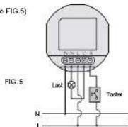
3.3 Wiring
3.2.1 Normal operation (See FIG.5)
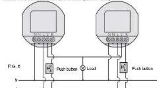
3.3.2 Two detectors control a load (See FIG.6)
3.2.3 One detector controls staircase time switch (Time knob sets at 1s) (See FIG.7)
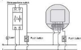
FIG.7
3.4 Installation procedure
The Mc Guard can be wall flush mounted with European standard junction box. The existing switch with 2-gang or more can be replaced by Mc Guard. (See FIG. 8)
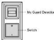
FIG. 8
3.4.1 Push mount with European standard junction box
3.4.1.1 Disassemble the plastic frame and front cover from the detector.
3.4.1.2 On crew the terminal and refer to the wing diagram (See FIG.5 FIG. 6 to insert the power cable into the corresponding terminals).
FIG. 7) to insert the power blocks into the top section of a minimum block. Please be noted to strip off 6 - 9mm of cable sheathing by tool (See FIG.9).
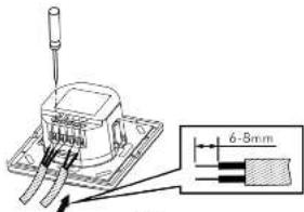
FIG. 9
3.4.1.3 Screw the terminal and make sure that wine are securely feed.
3.4.14 Put the Mirea detector into the European junction box (S—FIG. 10-A)
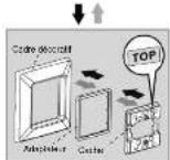
3.4.1.5 The adapter is applied on the loop of the decorative frame (See
FIG. 10-B). Then the press cover screws lock in inner cover. At last,
placing the surface cover to finish the installation (See FIG.10-C - FIG.10-F)
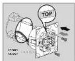
FIG 10-A
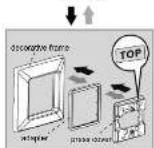
FIG 10-B
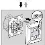
FIG 10-C
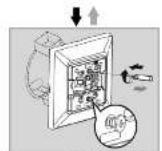
FIG 10-D
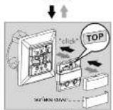
FIG 10-E
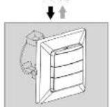
FIG 10-F
→ Installation procedure
→ Diamente procedure
3.5 Dismantle the plastic frame
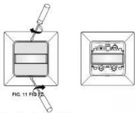
To dismantle a fixed Mc Guard, please refer to FIG.10-A to FIG.10-C & FIG.11 and use the proper screwdriver to take off the covers.
4 OPERATION
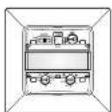
4.1 Open the top cover
4.1.1 Open the covers at upper and down the lens, you can see the slide switch and klops. (See Fig 11 and 12) Adjust them as you desired.
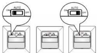
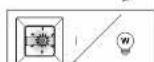
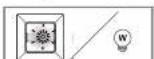
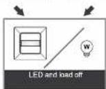
4.1.2 Side switch function (See FIG. 13)
AUTO: Set slide switch at the middle, detector is in AUTO mode. ON: Push the slide switch leftward to ON position ON mode is activated. Load will continue ON for 4hrs, LED flashes on 1sec and off 5sec, then return to AUTO mode automatically. Even slide switch is set to ON, detector enters into AUTO mode once the power is re-supplied again.
OFF: Push the slide switch rightward to OFF position, detector is in OFF mode, lighting keeps OFF permanently.
ON
AUTO
OFF
4.1.3 After finishing the settings, put the covers back.
4.1 Time, Mic & Lux knob setting
| NOTE |
| Make sure the slide switch is on the position of AUTO while adjusting the knob. |
| TIME FR 300 150 200 150 200 150 200 150 200 150 200 150 200 150 200 150 200 150 200 150 200 150 200 150 200 150 200 200 200 200 200 200 200 200 200 200 200 200 200 200 200 200 200 200 200 200 200 200 200 200 200 2 |
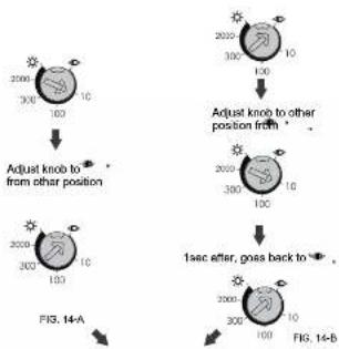
4.3 Lux learning function with knob Learning procedure:
4.2.1 Adjust the knob to when the ambient light level matches with the desired value (See FIG.14-A)
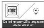
4.2.3 Then the load is off. LED starts to flash slowly indicating entering into
learning mode. Learning will be completed within 25 seconds. 64 onwards, the LED and low will save on 5ms or LED flash quickly.
Afterwards, the LED and load will keep on 5sec or LED flash quickly for 5sec and load is off to confirm successful learning (See FIG. 14-C) 4.2.4 After learning procedure, the detector returns to AUTO mode with LED and load being off
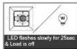
LED and load keep on 5sec the actual light level range is 10 · 2000Lux)
LED flashes quickly for 5sec & Load is off (the actual light level range is out of 10 - 200CLux)
Detector switches to AUTO mode (FIG. 14-C)
NOTE
- When the actual light level is out of the range 10 - 2000Lux, detector will learn 25sec, then the red LED flashes quickly for 6sec. When the actual light level is below 10Lux, Lux value is set to 10Lux, or is above 2000Lux, Lux value is sell to 2000Lux.
- Installer should be away from the detector to avoid affecting the luminous flux that reaches the detector when leaning Lux value.
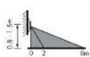
4.4 Usage of lens shield label
The attached lens shield label is used to reduce the detection range. With the different numbers of labels used, the different coverage can be obtained. Fox example, to install the detector at the height of 1.2m, the detection range refer to FIG. 15.
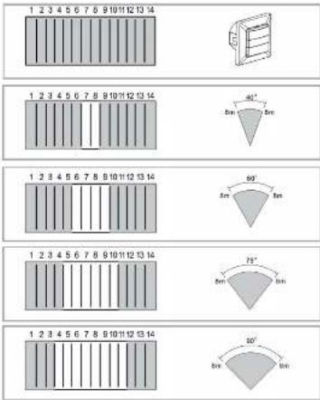
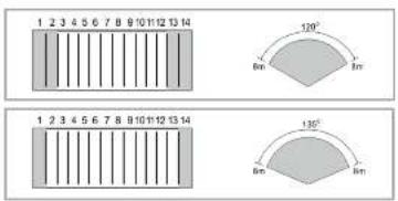
FIG. 15
4.4.5 Walk Test
NOTE
LED will turn on for 65sec at first time to switch the power on of detector or power is re-supplied again after the power is shut off, then turn off. During the of warming up period, the load is uncontrolled by Lux setting. Once any movement is detected after warming up period, it will enter into normal mode. If no movement is ceded within 15sec, load will turn off automatically and won't be controlled by pre-set timer but enter into standby mode immediately.
4.5.1 LED function
4.5.1.1 The LED of Mc Guard is behind the lens. (See FIG. 16) 4.5.1.2 In the walk test, LED will turn on for 2 sec once the detector is triggered. It is uncontrolled by Lux setting and can be regarded as indicator. Under manual on 4hrs mode, LED turns ON 1sec and OFF See as indication.
4.5.1.3 LED remains OFF either in AUTO mode or OFF mode.
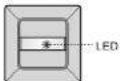
FIG. 15
4.5.2 Test procedure
The purpose of conducting walk test is to select a proper installation place to get the best detection range. Set the slide switch at the position of AUTO, TIME knob to "Test", then conduct a walk test referring to step 4.5.2.1 to 4.5.2.7 and Lux is displayed (Sea FIG. 17).
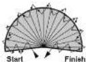
FIG.17
4.5.2.1 Install the detector correctly, refer to FIG.5 - FIG.7 to make sure correct wiring
correctming.
4.5.2.2 Switch the new
4.5.2.3 Walk from outside across to the detection pattern, once the detector is triggered, LED and load will all turn on for 2sec.
4.5.2.4 Refer to point "4.4 Usage of lens shield label", detection range and angle can be changed by adjusting lens shield.
4.5.2.5 Repeat the step 4.5.2.3 and 4.5.2.4 until it meets user's demands.
(See FIG. 3)
5 TROUBLE SHOOTING
When Detector works abnormally, check assumptive problems and suggested solutions in following table that be will hopefully to solve your problem
| Problem Possible cause Suggested solution | ||
| LED does not turn on. | 1. Power does not switch on.2. Incorrect wiring. | 1. Switched on the power.2. Refer to wiring diagrams and correct wiring correspondingly. |
| Lights do not turn on. | 1. Incorrect wiring.2. Defective load.3. The slide switch is set at OFF. | 1. Refer to wiring diagrams and correct wiring correspondingly.2. Replace the detective load with a new one.3. Adjust slide switch to AUTO or ON. |
| Lights do not turn off. | 1. TIME setting is too long or detector is continuously triggered.2. Incorrect wiring. | 1. Setting TIME at test mode, check whether the detector is resistance triggered. Keep away from detection zone to avoid activating detector2. Refer to wiring diagrams and correct wiring correspondingly. |
| Push button does not work | 1. Incorrect wiring.2. Defective switch. | 1. Please check if the push button is connected between R and L.2. Replace the push button with a new one. |
| Nuisance triggering | There are heat sources or any objects which may sway in the wind within the detection field. | Avoid sliding the detector toward any heat sources, such as air conditioners, electric fans, inulators or any highly reflective objects. Make sure there are no swaying objects within the detection field. |
NOTE
- Do not attempt to open or repair the unit without qualified electrician while
It is misinfected.
- The following conditions may cause lower sensitivity:
- In very foggy nights, the sensitivity may be less due to moisture collecting on the lens.
- In very hot days, the sensitivity may be less since high ambient
temperature is close to body temperature
- In very cold days when heavy clothing is dressed, especially the facial
area is covered, very little heat will be emitted from the body causing the unit to be less sensitivity.
- Cleaning wipe with dry cloth only. Soap or rough cloth may damage the detector lens.
7 GUARANTEE
GROTHE GmbH presence sensor is manufactured according to the latest techniques and subjected to quality control. It however, a date should occur. GROTHE GmbH provides a warranty to the following extent.
- The warranty covers 24 months from date of purchase of the device by the final end user. Compliance with the claim deadline is to be demonstrated by voucher of purchase date by means of an included invoice, delivery note, or similar document.
- The guarantees includes the correction or resupply of a device (according to our discretion) if the function of the device is limited or non existing due to proven material or manufacturing errors.
- The warranty does not cover damage during the transport. Moreover, damages on account of not following the instruction concerning installation and unprofessional installation of the device.

URMET GROUP
GROTHE GmbH
Löbstrasse 27
D-63773Hannaf
info@grothe.de
www.arolthe.cn
Lux * (page programmation
10 lux - 2000 lux)
80 x 80 x 51.5mm (Figure 1)
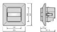
Figure 1
3 INSTALLATION ET CÂBLAGE
Figure 10-A
Figured 10-B
↓↑
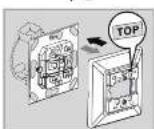
Figure 10-C

Figure 10-D
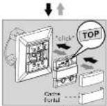
Figure 10-E
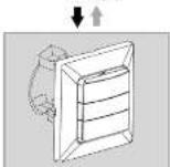
Figure 10-F
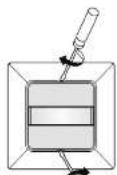
Figure 11 Figure 12
1
[Non-Text]
广力云智慧零售收银系统
25 × (1 × 18W); 12 × (2 × 18W);
5 x (1 x 36W); 7 x (2 x 36W);
10 x (1 x 58W); 5 x (2 x 58W)
Leclampen: Max. 400W
Spaarlampen : Max. 600VA / 400W
(inkl. CFL + PL Lampe)
2 PRODUCTBESCHRIJVING
80 x 80 x 51.5mm (Affecting 1)
Albeselding 1
3 INSTALLATIE EN BEDRADING
3.4 Installatie
The image is too blurry to recognize any text content.
de obiect, e eardeped