McGuard PM-AP HR - Motion detector GROTHE - Free user manual and instructions
Find the device manual for free McGuard PM-AP HR GROTHE in PDF.
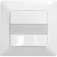
| Product type | Motion detector / Presence detector |
| Brand | GROTHE |
| Model | McGuard PM-AP HR |
| Power supply | 220-240 V~, 50/60 Hz |
| Max load (incandescent lamps) | 2000 W |
| Max load (AC halogen lamps) | 1000 W |
| Max load (low-voltage halogen lamps) | 1000 VA / 500 W |
| Max load (magnetic fluorescent tubes) | 1000 VA / 900 W |
| Max load (electronic fluorescent tubes) | 600 VA / 400 W |
| Detection angle | 360° |
| Detection range (diameter) | Up to 16 m (at 10 m height) |
| Recommended mounting height | 10 m |
| Brightness threshold adjustment | 10 lux to 2000 lux (∞) |
| Adjustable time delay | 5 s to 30 min (test: 1 s) |
| Operating temperature | 0 °C to +45 °C |
| Protection rating | IP54 |
| Dimensions | ∅115 mm x 45 mm |
| Functions | Automatic mode, test mode, IR remote control (optional), lens covers for masking |
| Safety | Installation by qualified technician; circuit breaker 250V/10A type C required |
| Maintenance | Clean with a soft, dry cloth. Do not use abrasive products. |
| Spare parts | IR remote control (ref. IR-FB), lens covers |
| Warranty | 24 months from date of purchase |
Frequently Asked Questions - McGuard PM-AP HR GROTHE
User questions about McGuard PM-AP HR GROTHE
0 question about this device. Answer the ones you know or ask your own.
Ask a new question about this device
Download the instructions for your Motion detector in PDF format for free! Find your manual McGuard PM-AP HR - GROTHE and take your electronic device back in hand. On this page are published all the documents necessary for the use of your device. McGuard PM-AP HR by GROTHE.
USER MANUAL McGuard PM-AP HR GROTHE
natural_image
Simple line drawing of a rounded rectangular object with a circular hole, resembling a mechanical component or housing (no text or symbols)10 x (1 x 58W); 5 x (2 x 58W)
LED Lampen : Max. 400W
Energiespar Lampen : Max. 600VA / 400W
natural_image
Technical drawing of a mechanical part with circular and rectangular features, dimensioned as φ115 (no text or symbols)Bid 6
3.4 Installation
LED and Last and Aus
4.3.2 Gehtest
(wallmounted) for hight ceilings

natural_image
Simple line drawing of a rounded rectangular object with a circular hole, resembling a mechanical component or housing (no text or symbols)INSTALLATION MANUAL
TECHNICAL SPECIFICATIONS
Rated Voltage: 220V-240V\~50/60Hz
Load Load for Lighting:
Incandescent Lamp: Max. 2000W
AC Halogen Lamp : Max. 1000W
LV Halogen Lamp : Max. 1000VA / 600W
(traditional) May 1000
MAX. 1000VA7900W (electronic)
Fluorescent Lamp
Max. 1000VA / 600W
(uncompensated)
Max. 900
25 x (1 x 16W): 12 x (2 x 18W):
15 x (1 x 36W); 7 x (2 x 36W).
10 x (1 x 58W); 5 x (2 x 58W)
LED Lamp : Max. 400W
Energie saving Lamp : Max. 600VA / 400W
(Inkl. CFL and PL Lamp)
Detection Range: 360° circular, up to ∅16m at height of 10m
Lux Adjustment Adjustable from approx. 10Lux bis (200) and
(learning range: 10Lux - 2000Lux)
Auto Off Zeit Adjustable from approx. 5Sek bis 30Min, and
Environmental Protection: IP54

Installation and assembly of electrical equipment
must be carried out by qualified electricians.
Contact a qualified electrician in the event of fault
or break down.
ACHTUNG
A circuit breaker (200VAC, 10%) type C according to EN80688-1 of load I shall be
- Do not impact un contradictive conditions.
- Do not open the enclosure frequently.
Turn off power when charge the light sources.
High in-rush current would be caused when subs of certain brands burned which might damage the unit permanently.
1 PACKAGE CONTENTS
| Pattern | Rubber washer | ||
| Item | Detector | Wood screws∅4 x 25.4mm+Rubber washers | Anchor |
| Quantity | 1 | 2 | 2 |
| Pattern | |||
| Item | Lens shield | Manual | IR-FB optional |
| Quantity | 2 | 1 |
2 FEATURES
2.1 Features
- Powerful relay and advanced technology are used to enable controlling all kinds of lighting loads.
- IR remote control is available for easy and quick selling.
- Manually switch on the load by wire connected to an external N.C. type
push button switch when the ambient light level exceeds the pre-set lux - Manual override for lighting on is enabled by using 18 remote control to
the time is turned to lighting the product by saving a formula that is control. - The ambient Lux value can be learned as the threshold for switching
on 7 off the loads by IR and VR if the provided Lux valuee do not match user's requirement. - A red LED is built-in as an indicator for test triggering and IR setting.
- Quick plug-in terminal block is used for easy and quick wiring.
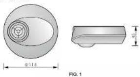
2.2 Dimension:
∅115mm × 45mm
natural_image
Technical drawing of a mechanical part with cross-sectional view and dimension label (no text or symbols beyond measurement annotations)3 INSTALLATION AND WIRING
Please disconnect power completely and read the entire instruction manual carefully before installation.
3.1 Select a proper location
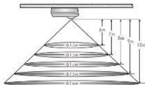
3.1.1 It is recommended to install the detector at the height of 10m, and the detection range can reach up to the diameter of 16m. (See FIG.2).
3.1.2 Helpful tips for installation
Since the detector is in response to temperature charge, please avoid the following conditions (Sea FIG. 3):
- Avoid the detector aiming towards the objects whose surfaces are highly reflective, such as images, mirrors, etc.
- Avoid the detector aiming towards the objects which may be swayed in the
wind, such as curtain, tall plants, miniature garden, etc.
- Avoid mounting the detector heat heat sources, such as heating vents, air conditioning, vents as dryers, lights, etc.
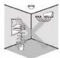
FIG 3-A

FIG. 3-B
3.2 Functions
3.2.1 Auto Mode
- Under Auto mode, the load will be on automatically when the movement is detected and the ambient light level is below the Lux selling value. When no movement is detected and the delay time has expired, the load will be off automatically.
- According to the changeable ambient light level, detector can postpone delay time of turning on and off its load to avoid unnecessarily switching due to rapid ambient light change:
Ambient light level changes from bright to dark:
If the ambient light level keeps to be lower than the preset Lux value for 10sec, the light will be automatically switched on after 10sec. (LED will be on 10sec for indication)
Ambient light level changes from dark to bright:
If the ambient light level continuously exceeds the switch off Lux value for 5min, there are different reactions according to the time setting value. Time setting >5min, the light will be automatically switched off after 5min. Time setting <5min, the light will be automatically switched off when the set time reached if no movement is detected during the 5min. But if there is movement detected within the 5min, the time will be reset upon detection and until 5min later, the light is switched off.
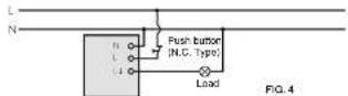
3.2.2 Push button function
The load can be manually switched on by using an external push button
switch (N.C. 10A type), See FIG.4 - FIG.6. When the load is off, it can be switched up by a stand press (1sec) on push button switch and Lut is
disabled on by a short press, 1926, on each section switch and EAX is disabled. After the load is switched on manually, the load can be
automatically switched off if no movement is detected and the delay time has expired.
3.3 Wiring
3.3.1 One load is controlled by one detector (San FIGA).
3.3.2 One load is controlled by two detectors to enlarge detection range (See FIG.5).
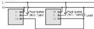
FIG.5
3.3.2 One detector controls staircase time switch (Time is set to 18 . See FIG. 6).
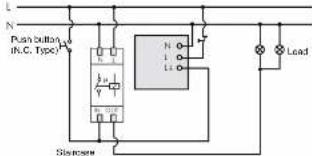
Lighting line
FIG.6
3.4 Installation procedure
3.4.1 Surface mount with ceiling board.
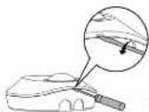
3.4.1.1 Use flat head screwdriver to take off the decorative cover (See FIG.7).
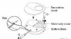
3.4.1.2 Unscrew the 4 screws on main body cover to separate it from bottom base (See FIG.8).
- 2017年 ,
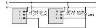
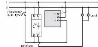
FIG.6
3.4.1.1 Use flat head screwdriver to take off the decorative cover (See FIG.7).
FIG. 8
3.4.1.3 There are 5 pairs of knockouts with various distances from 50mm to 84mm on the bottom base to be selected for different mounting applications (See FIG.9-A). Select two same figures on both ends for the corresponding distance for fixing (See.9-B).
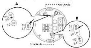
FIG. 34
| NO. | A | B | The distance between A and B |
| 1 | 56 | 56 | 56mm |
| 2 | 60 | 60 | 60mm |
| 3 | 70 | 70 | 70mm |
| 4 | 80 | 80 | 80mm |
| 5 | 84 | 84 | 84mm |
FIG. 9B
3.4.1.4 The cables can be led through either from side or bottom sides. To feed AC power cables through the side entry holes, please use the cutting pliers to break the cable entry knockouts on the side of junction box, then insert cables into junction box and feed through it. Strip off 6 - 8mm of cable sheathing for wiring (See FIG. 10).
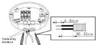
FIG.10
3.4.1.5 Choose proper knockouts to fix the bottom base on the surface of ceiling board with 2pcs wood screws (See FIG.11).
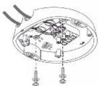
FIG. 11
3.4.1.6 Refer to the wiring diagrams (See FIG.4 - FIG.6) for correct cable connections and refer to FIG.12 to assemble detector with the bottom base.
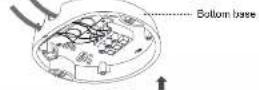
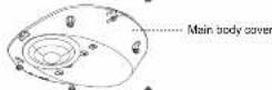
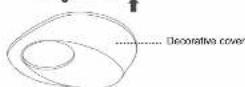
FIG. 12
3.4.1.7 Put on the decorative cover and restore power supply
3.4.2 Surface mount with European standard junction box.
3.4.2.1 Pull out AC power cables from European standard junction box (See FIG.13), then strip off 6 - 8mm of cable sheathing for wiring.
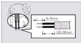
FIG. 13
3.4.2.2 Feed the power cables through bottom base, please use the screwdriver to break the cable entry knockouts on the bottom base (See FIG.14).
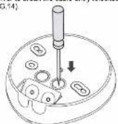
FIG. 14
3.4.2.3 Select appropriate distance from the bottom base mounting holes, to fix the bottom bass onto European standard junction box with two wood screws (See FIG.15)
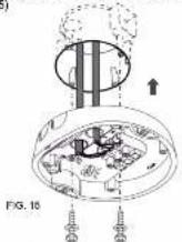
3.4.2.4. Refer to the wiring diagrams (See FIG.4 - FIG.6) for correct cable connections and refer the FIG.12 to assemble detector with the bottom base.
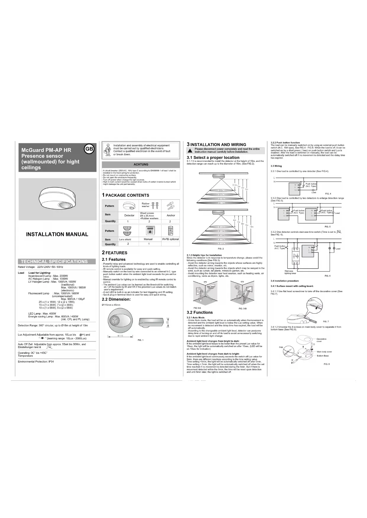
4.1 Setting of Time, Meter and Lux
| Time m/s | Set today off time for lighting | Range: Adjustable from approx. 3.5Km, to 20 Min. cm : 1.5Km mode, local and red LiCl will be 2 5Km on, 2.5Km off. [Fe]: Short impulse mode for stroke rate their switch control (cool) can be 1.5Km on, 95Kc off. |
| Meter + | Set the cotlection range | Range: Adjustable at 2h to -1.5pprec @ Km, H=10m. |
| SAR 20000000000000000000000000000000000000000000000000000000000000000000000000000000000000000000000000000 | Set the light value for emerging on level | Range: Adjustable at 2h to 1000. [●] learn the actual ambient light level (No 200000000000000000000000000000000000000000000000000000000000000000000000000000000000000000000000000 |
4.2 Lux learning function with knob
Learning procedure:
4.2.1 Adjust the knob to ▶ when the ambient light level matches with the roared value (See FIG. 18-A).
4.2.2 When the knob is set to • originally, it should be adjusted to other
position more than 1 sec, then goes back to ● (See FIG.18-B)
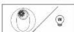
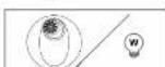
4.2.3 Then the load is on LED starts to flash slowly indicating entering into learning mode. Learning will be completed within 25 seconds. Afterwards, the LED and load will keep on Iacc or LED flashes quickly for Iacc and load is off to confirm successful learning (See FIG. 16-C).
4.2.4 After learning procedure, the detector returns to AUTO mode with LED

↓

Adjust knob to other
position from
Adjust knob to *
from other position

1sec after, goes

FIG. 16-A
after, goes
Back to 400
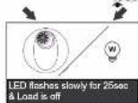
FIG. 16-B
LED and load keep on 5sec
(the actual light level range in 10, 2750 L/s)
是 10 * 2000LOX)
LED flashes quickly for 5sec
Load is off (the excellent level range is out of 10-200%
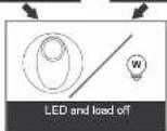
Detector switches to AUTO
Bild 16-C)
NOTE
- When the actual light level is out of the range 10 - 2000Lux, detector will learn 25sec, then the red LED flashes quickly for 5sec. When the actual light level is below 10Lux, Lux value is set to 10Lux, or is above 2000Lux, Lux value is set to 2000Lux.
- installer should be away from the detector to avoid affecting the luminous flux that reaches the detector when learning Lux value.
4.3 Test mode
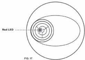
4.3.1 LED function
There is a built-in red LED as an indicator for infrared signal reception and test mode status (Sec. FIG. 17).
4.3.1.1 In case the IR-11 remote control is used, the detector receives signal from it, then red LED will flash 2sec quickly to indicate successful signal reception.
4.3.1.2 LED can be used as an indicator in walk feet so that load is no need to be connected
4.3.2 Walk test
The purpose of walk test is to select a proper installation place to get the boat detection range. Set motor knob at "+1, time at "last" (refar to step 4.7), then you can conduct a walk test and the detector is uncontrolled by Lux setting. (See FIG. 18).
Note
When the power is connected for the first time or it is resupplied after shutting off, the detector will enter into 60sec warm up mode. During which, LED and the load can be switched on for 60sec regardless of the time knob of detector is set to any modes, and then off. After warming up is finished, the detector will enter into Auto mode and work according to knob settings.
FIG.10
Test procedure
4.3.2.1 Tester must be within the detection coverage
4.3.2.2 Switch on the power. 4.3.2.3 Walk from outside access to the detecting pattern. Real LED will turn on
for 2sec once the movement is detected
4.3.2.4 Adjust meter knob to change coverage
4.3.2.5 Repeat step 4.3.2.3 to 4.3.2.4 until it meets user's demands.
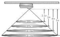
4.4 Usage of lens shield
4.4.1 The detector has provided 2 lens shields for masking the undesired detection area. Each lens shield has 3 layers (Layer A / Layer B / Layer C), each layer includes 6 small segments and each small segment can cover 30^ detection angle. For example, install the sensor at the height of 10m, the detection range can reach up to 1m diameter if the two complete lens shields have been used, and up to 12m diameter if the A & B layers of two lens shield has been used, and up to 14m diameter if only the A layer of two lens shield has been used, and up to 16m diameter if no lens shield has been used.
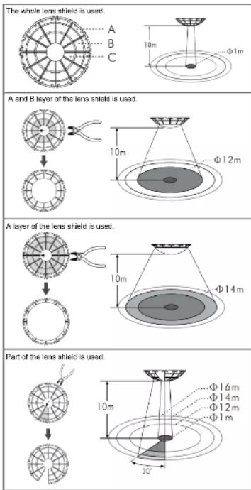
FIG.19
The shadow part of the lens shields in the FIG. 19 is refer to the cut off parts.
4.4.2 Fixing lens shield: There is circular hook on the back of the decorative frame and the lens shield is designed with a circular groove. The lens shield can be filled by joining the groove of lens shield with 1st corresponding hook on the decorative frame (See FIG.20).
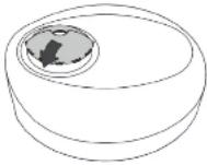
FIG. 20
5 TROUBLE SHOOTING
When the detector works abnormally, check assumptive problems and suggested solutions in following table that will hopefully solve your problem.
Problem Possible cause Suggested solution
| Lighting device does not turn on | 1. Power does not turn on.2. Incorrect wiring3. Improper knob setting4. Malfunctioned load. | 1. Switch on the power.2. Refer to wiring diagrams (FIG. 4 - FIG. 8) and check if the load is malfunctioned.3. Check if knobs are set to the correct position, then supply the power to check if the LED will turn on.4. Replace the disabled load with a now one. |
| Lighting device does not turn off | 1. Incorrect lime setting.2. Detector is nuisance triggering.3. Incorrect wiring. | 1. To test the delay time specified on lime knob and check detector is nuisance triggered lighting device does not turn off as the delay time is reached.2. Keep away from detection coverage to avoid activating detector while doing the test.3. Make sure load and wire are connected correctly. |
| LED does not turn on | 1. Out of the detection range.2. No power is supported.3. 'Timer knob setting is last,' test.4. Incorrect wiring. | 1. Walk within the effective detection range (∅16m).2. Switch on the power.3. Turn the knob position to 'test'.4. Refer to wiring diagrams (FIG. 4 to FIG. 8) |
| Nuisance triggering | There are heat sources, highly reflective objects or any objects which may be swayed in the wind within the detection coverage. | Avoid aiming the detector toward any heat sources, such as air conditioners, electric fans, heaters or any highly reflective surfaces. Makes sure there are no swaying objects within the detection coverage. |
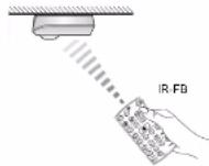
6 OPTIONAL PURCHASE UNIT
6.1 The detector can also be controlled by the infrared remote control to make the operation more easier and convenient (See FIG.24)
6.2 Push button function:
Tester
Funktion

To set load on for 6hrs
- By pressing Ⓞ button, the load of deflector will be turned on for 0 hours.
- Load will be turned off after 8 hours and return to auto mode. Or press button again to exit this 8 hours on mode during this period, detector will be return to auto mode.
Or switching oil power supply of presence detector for 5 sec and re-supply it again to end detector to auto mode.
- Lout ran he lived in all made by pressing a button on made.
To set level off for 85bp
- By pressing button, the load of detector will be turned off for 8 hours.
- Detector will return to auto mode after 8 hours. Or press button again to exit the 'hours off mode' during this mode, detector will return to auto mode.
Or switching power supply off presence detector for basic and no supply it again to lead detector to auto mode.
- Load can be load to on mode by pressing button under off mode. To lock IR buttons By pressing button, IR buttons will be installed and open function
- By clearing burnout, PC control will be tested with no key function. Is workable (Except of) human).
Unlock IR buttons
- By pressing button, IR buttons will be unlocked. Thereafter IR remote controller can be used to set presence detector.

Ex-changing auto mode and semi auto mode - By pressing 📂 firstly, detector enters into auto mode with detector's red LED flashing quickly for 2sec no matter it is locked or not. Then, press it again, detector enters into semi-auto mode with detector's red LED being on for 2sec.
To save latest setting values and duplicate to other detector 1. Set the desired Lux and Time values on one detector by using II remote controller.
-
Then by pressing ⏻ button for approx. 3sec aiming to above detector, the Lux and Time settings of this detector will be saved into this IP sample unless preferred by delecting an LED shaker.
-
By pressing ⊖ button system for approx. 1sec siming to a new
detector, the saved settings can be duplicated to the new detectors. 4. Transfer the settings to detectors desired by repeating above last stop. If no data is saved in IR remote controller, detector has no repetition after press (▶) button.
- Battery removed for more than 5 sec or ⏻ button is pressed, all the data in IR remote controller will be closed.
RESET
To reset settings on Presence Detector By pressing button, all settings on presence detector will go back to knob settings, and all MEMO calls will be delayed.

To adjust Lux value By pressing corresponding button, the selected light level threshold will be set to presence detector for switching on the connected load.

(1) AD = BD = 1

To read-in the actual light level Actual light level can be read in as threshold for switching the connected load, if the set lux values do not match user's desired value. The steps are as below. Press class: button fill detector is red LED flashing to enter into learning mode, learning time is 10sec. Then the actual light level is read-in confirmed by both load and LED turn on for basic to indicate IR learning, successfully and then turn off. Afterwards it returns to auto mode. Note: If the ambient light level is out of the range of 10 - 2000Lux, detector will learn for 10sec., then LED flashes quickly for best, and the alternative of 10Lux or 99 value will be stored depending on under 10Lux or above 2000Lux value.

To set delay off TIME By pleasing corresponding button, the desired switching off delay time of load can be exactly set, it is confirmed by detector's LED flashing for 200c.

Test mode By pressing button ⏻ to enter into Test mode, it is confirmed by detector's LED for 2sec. Walking through the detection coverage, both load once detector is triggered (Reaction is regardless of Lux value).

Short impulse mode By pressing (1) button to enter into short impulse mode, it is confirmed by detector's LED flashing for 2sec. Load will be on 1sec and 5sec off when detector detects movement and the preset Lux value under short impulse mode.
6.3 IR Trouble Shooting
When remote controller IR works abnormally, please check assumptive problems and suggested solutions in below chart that hopefully solve your problem.
| Problem Possible cause Suggested solution | ||
| Detector fails to receive signal | 1. Exceed the transmission range. | 1. Operate within transmission angle ( ± 35^ ), and ensure IR aiming directly to the detector.2. Replace a new battery. |
| 2. Low battery power. | ||
| 3. Detector works abnormally. | 3. Check the trouble of detector, then refer the TROUBLE SHOOTING of detector manual for repairing. | |
| No signal | 1. Low battery power. | 1. Replace battery. |
| 2. Press two or more buttons once. | 2. Press one button once. | |
| 3. The battery insulation sheet is not look out. | 3. Take out the battery insulation sheet. | |
| Fail to transmit signal | In locked mode. | Unlock IR |
7 GUARANTEE
GROTHE GmbH presence sensor is manufactured according to the latest techniques and subjected to quality control. If however, a defect should occur, GROTHE GmbH provides a warranty to the following extent.
- The warranty covers 24 months from date of purchase of the device by the final end user. Compliance with the claim deadline is to be demonstrated by voucher of purchase date by means of an included invoice, delivery note, or similar document.
- The guarantee includes the correction or resupply of a device (according to our discretion) if the function of the device is limited or non existing due to proven material or manufacturing errors.
- The warranty does not cover damage during the transport. Moreover, damages on account of not following the instruction concerning installation and unprofessional installation of the device.

URMET GROUP
GROTHE GmbH
Löhestrasse 22
D. 50770 Uwara
D - 53773 Henf
info@arolba-ris
www.online.de
GROTHE GmbH
Löhestrasse 22
D. 50770 Uwara
D - 53773 Henf
info@arolba-ris
www.online.de

Short impulse mode By pressing (1) button to enter into short impulse mode, it is confirmed by detector's LED flashing for 2sec. Load will be on 1sec and 5sec off when detector detects movement and the preset Lux value under short impulse mode.
(1)
HAWING
HAWING
[Non-Text]
[Non-Text]
natural_image
Simple line drawing of a rounded object with a circular hole, resembling a stylized helmet or cap (no text or symbols)natural_image
Technical drawing of a mechanical part with cross-sectional view and dimension label (no text or symbols beyond measurement annotations)3 INSTALLATION ET CÂBLAGE
If the shibent light level keeps to be lower than the preset Lux value for 10sec, the light will be automatically switched on after 10sec. ILED will be
on 10sec for indication)
Figure 10
6 APPAREIL DISPONIBLE EN OPTION
natural_image
Simple line drawing of a rounded rectangular object with a circular hole, resembling a mechanical or architectural component (no text or symbols)10 x (1 x 58W); 5 x (2 x 58W)
Ledlampen: Max. 400W
Spaarlampen : Max. 600VA / 400W
(Inkl. CFL + PL Lampe)
Afteriding 34
| Nr. | A | B | Afstand tussen A en B |
| 1 | 56 | 56 | 56mm |
| 2 | 60 | 60 | 60mm |
| 3 | 70 | 70 | 70mm |
| 4 | 80 | 80 | 80mm |
| 5 | 84 | 84 | 84mm |
Abbeiding 88
Alboelding 10