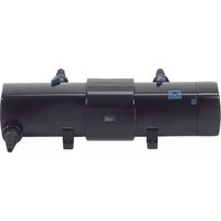
Bitron C 72 - Water filter OASE - Free user manual and instructions
Find the device manual for free Bitron C 72 OASE in PDF.


| Product type | UVC clarifier with by-pass (water filter) |
| Model | Bitron C 72 |
| Brand | OASE |
| UVC lamp power | 72 W |
| Supply voltage | 230 V / 50 Hz |
| Recommended water flow | Up to 10,000 l/h (with specific inlet nozzle for lower flow rates) |
| Water temperature range | +4 °C to +30 °C (fresh water); +4 °C to +25 °C (salt water) |
| Main functions | UVC clarification, adjustable by-pass, automatic cleaning rotor, visual operation display |
| Maintenance and cleaning | Cleaning of quartz glass and rotor; replacement of UVC lamp after 8000 hours of operation |
| Safety | Protection by residual-current circuit breaker (30 mA max.); thermal safety cut-out; device head polarization |
| Wear parts | UVC lamp, quartz glass, O-ring for quartz glass, cleaning rotor |
| Repairability | OASE spare parts available online; easy replacement of lamp and quartz glass |
| Applications | Garden ponds, natural swimming pools, aquariums; stand-alone installation or on OASE ProfiClear, BioSmart, BioTec, BioTec Screenmatic filters |
| Housing material | UV-resistant plastic |
| Minimum distance from water | 2 meters (for pools or ponds with people) |
Frequently Asked Questions - Bitron C 72 OASE
User questions about Bitron C 72 OASE
0 question about this device. Answer the ones you know or ask your own.
Ask a new question about this device
Download the instructions for your Water filter in PDF format for free! Find your manual Bitron C 72 - OASE and take your electronic device back in hand. On this page are published all the documents necessary for the use of your device. Bitron C 72 by OASE.
USER MANUAL Bitron C 72 OASE
natural_image
Black-and-white photo of lotus flowers blooming in a pond, surrounded by reeds and rocks (no text or symbols)BITRON C UVC
EN Operating instructions
FR Notice d'emploi
natural_image
Exterior view of a black Bifron air purifier device (no visible text or symbols on body)
A
BTN0020
B
BTN0021
C
natural_image
Four technical diagrams showing mechanical assembly with cross-bracing, no text or symbols presentBTN0022
D
BTN0023
E
BTN0024
H
BTN0031
|
natural_image
Technical line drawing of a mechanical assembly with a magnified inset showing a component detail (no text or symbols)BTN0026
J
BTN0025
BTN0027
BTN0028
M
BTN0034
N
BTN0029
Translation of the original Operating Instructions

WARNING
- This unit can be used by children aged 8 and above and by persons with reduced physical, sensory or mental capabilities or lack of experience and knowledge if they are supervised or have been instructed on how to use the unit in a safe way and they understand the hazards involved.
- Do not allow children to play with the unit.
- Only allow children to carry out cleaning and user maintenance under supervision.
- Ensure that the unit is fused for a rated fault current of max. 30 mA by means of a fault current protection device.
- Only connect the unit if the electrical data of the unit and the power supply correspond. The unit data is to be found on the unit type plate, on the packaging or in this manual.
- Possible death or severe injury from electrocution! Before reaching into the water, always disconnect all units in the water that have a voltage of >12 V AC or >30 V DC from the power supply.
- A damaged connection cable cannot be replaced. Dispose of the unit.
Safety information
Electrical connection
- Electrical installations must meet the national regulations and may only be carried out by a qualified electrician.
- A person is regarded as a qualified electrician if, due to his/her vocational education, knowledge and experience, he or she is capable of and authorised to judge and carry out the work commissioned to him/her. This also includes the recognition of possible hazards and the adherence to the pertinent regional and national standards, rules and regulations.
- For your own safety, please consult a qualified electrician.
- Extension cables and power distributors (e.g. outlet strips) must be suitable for outdoor use (splash-proof).
- Protect the plug connection from moisture.
- Only connect the unit to a correctly fitted socket.
Safe operation
- Never operate the unit if either the electrical cables or the housing are defective!
- Do not carry or pull the unit by its electrical cable.
- Route cables/hoses such that they are protected from damage and do not present a tripping hazard.
- Only open the unit housing or its attendant components, when this is explicitly required in the operating instructions.
- Only carry out work on the unit that is described in this manual. If problems cannot be overcome, please contact an authorised customer service point or, when in doubt, the manufacturer.
- Only use original spare parts and accessories for the unit.
- EN -
- Never carry out technical modifications to the unit.
- Keep the socket and power plug dry.
- If the device is installed directly at the water (< 2 m), ensure that there are no persons in the water while it is operating.
Information about this operating manual
Welcome to OASE Living Water. You made a good choice with the purchase of this product Bitron C.
Prior to commissioning the unit, please read the instructions of use carefully and fully familiarise yourself with the unit.
Ensure that all work on and with this unit is only carried out in accordance with these instructions.
Adhere to the safety information for the correct and safe use of the unit.
Keep these instructions in a safe place! Please also hand over the instructions when passing the unit on to a new owner.
Symbols used in these instructions
Warnings
The warning information is categorised by signal words, which indicate the extent of the hazard.

WARNING
- Indicates a possibly hazardous situation.
• Non-observance may lead to death or serious injuries.

NOTE
Information for the purpose of clarification or for preventing possible damage to assets or to the environment.
Additional information
□ A Reference to a figure, e.g. Fig. A.
→ Reference to another section.
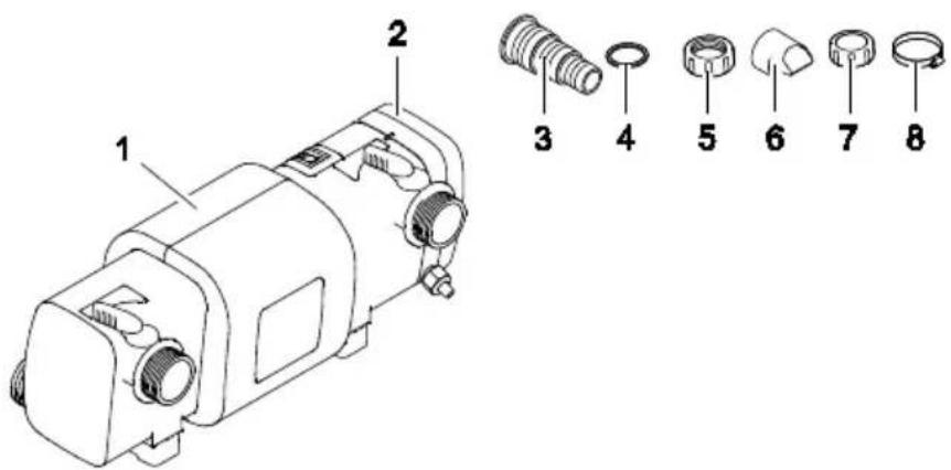
Scope of delivery
| ☐ A | Bitron C | ||
| 24W | 36W/55W/72W/110W | ||
| 1 | Casing | 1 x | 1 x |
| 2 | Unit head | 1 x | 1 x |
| 3 | - Stepped hose adapter, 19 ... 38 mm ( 34 ... 112") | 3 x | 2 x |
| - Stepped hose adapter for the inlet, 19 ... 50 mm ( 34 ... 2") | - | 1 x | |
| 4 | Flat seal for stepped hose adapters (3) | 3 x | 3 x |
| 5 | Union nut for fastening the stepped hose adapters (3) | 3 x | 3 x |
| 6 | Inlet nozzle for driving the cleaning rotor- Has to be inserted into the inlet for flow rates < 10000 l/h | 1 x | 1 x |
| 7 | Cover cap 38 mm ( 112" ) for closing the outlet | 1 x | 1 x |
| 8 | Hose clip 20 ... 32 mm | 2 x | 2 x |
| Hose clip 35 ... 50 mm | 2 x | 2 x | |
| Hose clip 40 ... 60 mm | - | 1 x | |
Product Description
Bitron C is a powerful UVC clarifier for controlling algae and harmful bacteria.
- The bypass technology ensures optimum irradiation of the dirty water even at high flow through rates.
- The cleaning rotor continuously removes soiling from the quartz glass.
- Individual regulation of the water flow rate allows optimum adjustment to the connected filter pump.
- Suitable for fitting to OASE filter systems ProfiClear, BioSmart, BioTec and BioTec Screenmatic.
- Integrated magnets protect the filter technology from calcium deposits.
• Visual function check of the UVC lamp. - Quick release system for easy lamp replacement.
Intended use
Bitron C, referred to as "unit", may only be used as specified in the following:
- For cleaning garden ponds, swimming ponds, pools and aquariums.
- Operate in accordance with instructions.
The following restrictions apply to the unit:
- Never operate the UVC lamp outside the casing or use it for any other purposes. The UVC radiation is harmful to the eyes and skin even in small doses.
- Never use the unit to convey fluids other than water.
- Never run the unit without water.
- Do not use for commercial or industrial purposes.
- Not to be used for sterilising drinking water or other fluids.
- Do not use in conjunction with chemicals, foodstuff, easily flammable or explosive substances.
Installation and connection
Operation with pool water or salt water
- For operation with pool water or salt water, the following limits must be adhered to:
| Type | Pool water | Salt water |
| pH value | 7.2 ... 7.6 | 7.5 ... 8.5 |
| Free chlorine | 0.3 ... 0.6mg/l | < 0.3mg/l |
| Bound chlorine | < 0.2 mg/l | - |
| Chloride content | < 200 mg/l | - |
| Salt content | - | < 3.5 % |
| Water temperature | +4 ... +30°C | +4 ... +25°C |
- Pool water or salt water can impair the appearance of the unit. Such impairments are excluded from the guarantee.
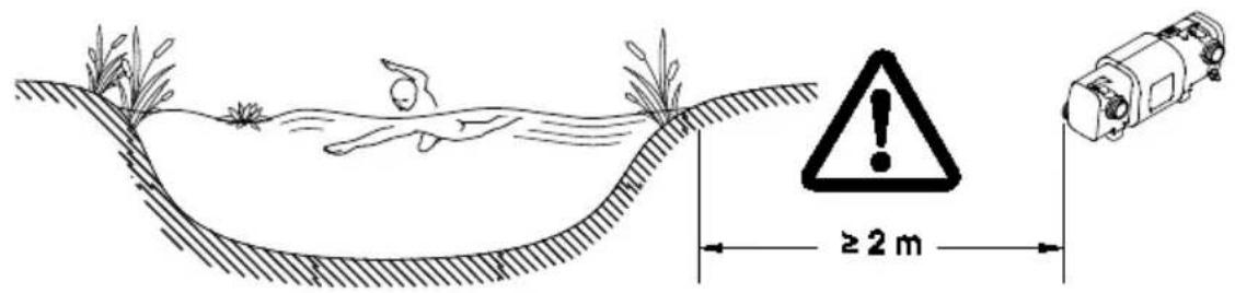
Distances to be adhered to
□ B
- Swimming pond or pool that may be accessed by people.
- Install the unit at least 2 m away from the water.
- Garden pond or aquarium:
- Install the unit at least 2 m away from the water.
- Allow sufficient space for carrying out maintenance work.
- Ensure that there is space of at least double the width of the casing for removing the unit head.
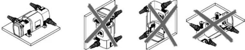
Solo operation
□ C
- Only install the unit in the permitted positions to ensure fault-free operation.
• Take the required distances into consideration. - Use suitable fastening material for the type of ground. Ensure that the fastening means securely hold the unit. Take the weight of the unit into consideration.
- Fit a slide valve in the water supply upstream of the inlet of the unit if the unit is to be installed below the water level. This allows the water supply to be shut off for maintenance work.
- EN -
Connecting the inlet
Use hoses that are suitable for a pressure of at least 1 bar.
How to proceed:
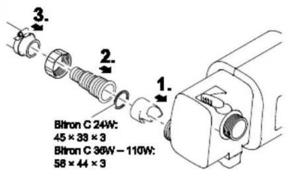
□D
Push the inlet nozzle into the inlet.
- The inlet nozzle is only necessary for a flow rate < 10000 ~l / h to ensure unimpaired rotation of the cleaning rotor.
Screw the hose connector with union nut and seal onto the inlet.
Slip the hose clip over the hose, fit the hose onto the hose connector and secure with the hose clip.
Connecting the outlet
How to proceed:
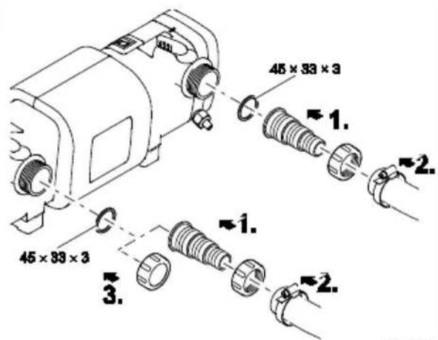
□ E
Screw the stepped hose adapter with union nut and seal onto the adapter.
Slip the hose clip over the hose, fit the hose onto the hose connector and secure with the hose clip.
Screw the cover cap with flat seal onto the outlet.
- The cover cap has to close the outlet opposite the inlet so that the main flow of water is guided along the UVC lamps and is exposed to the UV radiation for as long as possible.
Connect the unit to the flow-through filter.
• Take the required distances into consideration.
- Fit a slide valve in the water supply upstream of the inlet of the unit if the unit is to be installed below the water level. This allows the water supply to be shut off for maintenance work.
ProfiClear Premium / ProfiClear Classic / BioSmart
This section describes the connection of the UVC clarifying unit Bitron with a pump fed system.
- Please adhere to the instructions for use of the flow-through filter.
How to proceed:
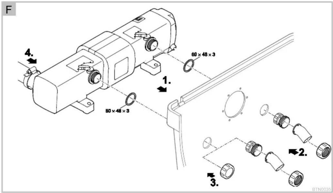
□ F, G
Insert the outlets with flat seals through the holes in the container wall.
Fitting the inlet:
- ProfiClear Premium: First screw the adapters onto the outlets and hand tighten. Then screw the 30^ inlet bends with the union nuts onto the adapters and hand tighten. Ensure that the openings point downward.
- ProfiClear Classic / BioSmart: Screw the inlet nozzles with the O rings onto the outlets and hand tighten.
Closing the bypass (optional):
- ProfiClear Premium: Screw the cover cap onto the outlet instead of the adapter and inlet bend.
- ProfiClear Classic / BioSmart: Screw the cover cap onto the outlet instead of the inlet nozzle.
Connect the Bitron to the filter pump. (→ Connecting the inlet)
BioTec ScreenMatic
- Please adhere to the instructions for use of the flow-through filter.
How to proceed:
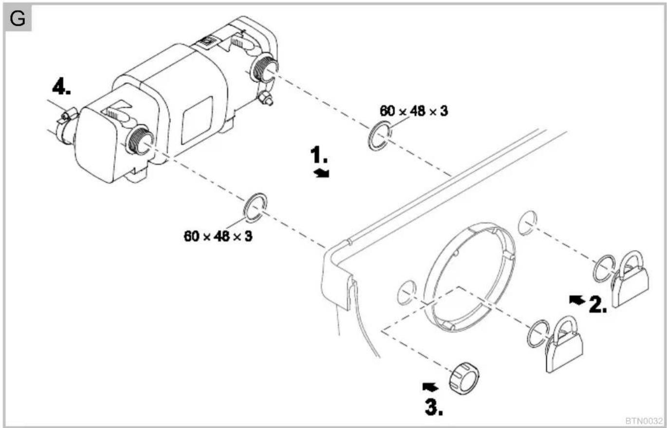
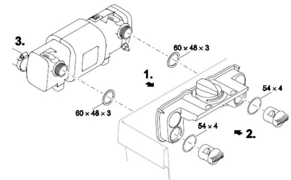
□H
Insert the outlets with flat seals through the holes in the container wall into the distributor.
Screw the distributor nuts with O rings onto the outlets and hand tighten.
Connect the Bitron to the filter pump.
Commissioning/start-up

WARNING
Possible death or severe injury from hazardous electrical voltage!
- Prior to reaching into the water, isolate (switch off and disconnect) all units/devices used in the water.
- Isolate the device (disconnect from the power supply) before carrying out any work on it.

NOTE
If the water flow is suddenly interrupted downstream of the outlet (e.g. with a slide valve), this can lead to a brief increase of pressure of more than 1 bar (water hammer). Possible consequences: The unit may be damaged.
- Switching off: First switch off the pump, then close the slide valve. If the unit is operated in a filter system, first take the filter system out of operation.
- Switching on: First open the slide valve, then switch on the pump. If the unit is operated in a filter system, start up the filter system last.
• Install the slide valve upstream of the inlet.

NOTE
New filters take approx. 3 to 4 weeks before the bacteria in the unit are fully established. During this time – or at a water temperature of <10 ^ – the filter may overflow. In this case the filter does not need to be cleaned.
- When using filter starter, medicines or pond water treatments, leave the UVC clarifying unit switched off for at least 36 hours so as not to impair their efficacy.
Prerequisite
- First switch on the pump, then the UVC clarifier.
- Check all connections for leaks.
Switching ON/switching OFF
- Switching on: Insert the power plug into the socket.
- The unit switches on immediately.
- Switching off: Disconnect the power plug.
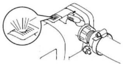
Check the function.
□1
- The function display is lit when the UVC lamp is switched on.
- An alternating light/dark blue glow in the inspection window indicates that the cleaning rotor is rotating.
Setting the bypass
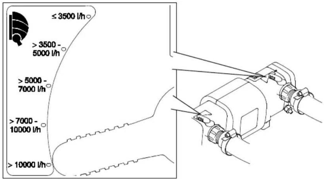
The flow rate is controlled by the bypass. Depending on the setting, part of the water flows from the inlet directly out via the opposite outlet. The remaining part of the water is irradiated by the UVC light and flows out via the second outlet. Maximum cleaning capacity is only achieved with an optimum setting.
How to proceed:
□ J
- Set both rotary handles to the delivery rate of the filter pump.
Remedy of faults
| Malfunction | Cause | Remedy |
| Water remains cloudy (green water). | The water is extremely soiled. | - Remove algae and leaves from the pond.- Change the water. |
| Insufficient delivery rate of the pump | Check the installation. | |
| The quartz glass is soiled. | Clean the quartz glass. | |
| The quartz glass is scratched. | - Replace the quartz glass ( Cleaning the quartz glass)- If the profile is worn, replace the cleaning rotor ( Cleaning the quartz glass) | |
| The cleaning rotor is not turning.- Check the inspection window: An alternating light/dark blue glow indicates that the cleaning rotor is rotating. | - Clean the cleaning rotor and quartz glass ( Cleaning the quartz glass)- If the delivery rate of the pump is < 10000 l/h , use an inlet nozzle for driving the cleaning rotor.- If the profile is worn, replace the cleaning rotor ( Cleaning the quartz glass) | |
| The UVC lamp capacity is exhausted. | Replace the UVC lamp after 8000 operating hours. | |
| Incorrect bypass setting | Correct the setting, observe the pump capacity. | |
| No or insufficient water flow at the outlets | Inlet nozzle clogged | Clean the inlet nozzle. |
| Outlets clogged | Clean the casing ( Cleaning and maintenance) | |
| UVC lamp is not lit. | Power plug not connected | Connect the power plug. |
| UVC lamp defective | Replace the UVC lamp. | |
| Connection defective | Check the electrical connection. | |
| Bitron C 55W/72W/110W: The unit has switched off due to overheating (safety switch-off). | Allow it to cool down; the unit will switch back on automatically. |
Maintenance and cleaning

WARNING
Possible death or severe injury from hazardous electrical voltage!
- Prior to reaching into the water, isolate (switch off and disconnect) all units/devices used in the water.
- Isolate the device (disconnect from the power supply) before carrying out any work on it.

CAUTION
Quartz glass and UVC lamp can break and cause cut injuries.
- Handle the quartz glass and UVC lamp with care.
Dismantling the unit head
How to proceed:
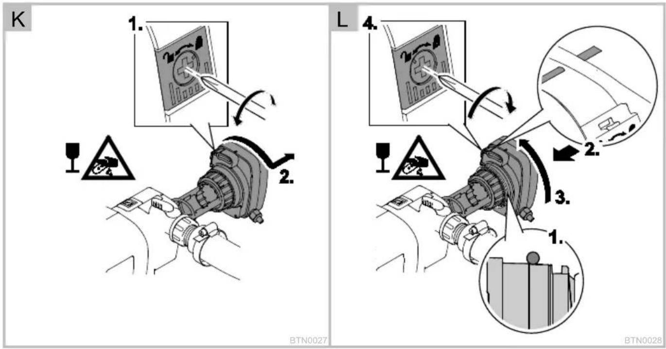
□K
Undo the locking screw in the safety engagement catch.
- Rotational direction "Lock open" symbol.
Press the safety engagement catch, turn the unit head counterclockwise as far as the stop and carefully pull it out of the casing.
- Thoroughly clean the inner and outer surfaces of the casing.

NOTE
For safety reasons, the UVC lamp can only be switched on when the unit head has been correctly fitted into the casing.
Fitting the unit head
How to proceed:
□L
Position the O ring in front of the recess at the unit head.
- Ensure that the O ring is clean; replace if damaged.
Carefully push the unit head with cleaning rotor into the casing up to the stop while applying light pressure.
- Ensure that the unit head is turned such that the markings on the unit head and casing are aligned.
Turn the unit head up to the stop.
– Ensure that the safety engagement catch engages.
Close the locking screw in the safety engagement catch.
- Rotational direction "Lock closed" symbol.
Cleaning the quartz glass

CAUTION
Quartz glass and UVC lamp can break and cause cut injuries.
- Handle the quartz glass and UVC lamp with care.

NOTE
If the water flow is suddenly interrupted downstream of the outlet (e.g. with a slide valve), this can lead to a brief increase of pressure of more than 1 bar (water hammer). Possible consequences: The unit may be damaged.
- Switching off: First switch off the pump, then close the slide valve. If the unit is operated in a filter system, first take the filter system out of operation.
- Switching on: First open the slide valve, then switch on the pump. If the unit is operated in a filter system, start up the filter system last.
• Install the slide valve upstream of the inlet.
Prerequisite: The device head is removed. (→ Removing the unit head)
How to proceed:
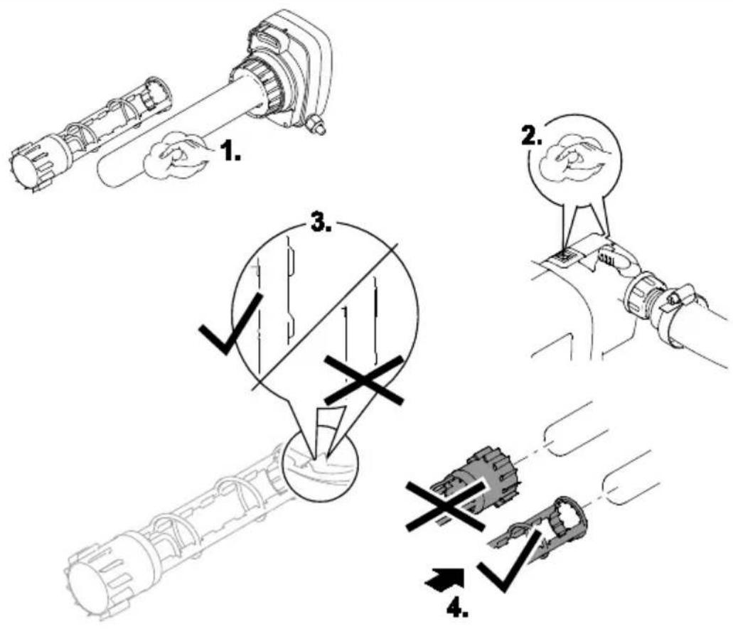
□M
Remove the cleaning rotor.
– Clean the cleaning rotor with a brush under running water.
- Wipe the quartz glass with a damp cloth.
- Replace the quartz glass if it is damaged or very scratched. (→ Replacing the UVC lamp)
Clean the inner and outer surfaces of the casing and inspection window.
Check the profile wear at both ends and the inner surfaces of the cleaning rotor.
- If the profile is worn, the cleaning rotor will rotate sluggishly and has to be replaced.
Push the cleaning rotor onto the quartz glass.
- Ensure that it is correctly positioned.
Fit the unit head. (→ Fitting the unit head)
Replacing the UVC lamp
Replace the UVC lamp after max. 8,000 operating hours (this corresponds to approx. one pond season with continuous operation). This ensures optimum filtering performance.
- Ensure that the identification and capacity data of the UVC lamps used correspond to the information on the unit type plate.
Prerequisite: The device head is removed. ( Removing the unit head)
How to proceed:
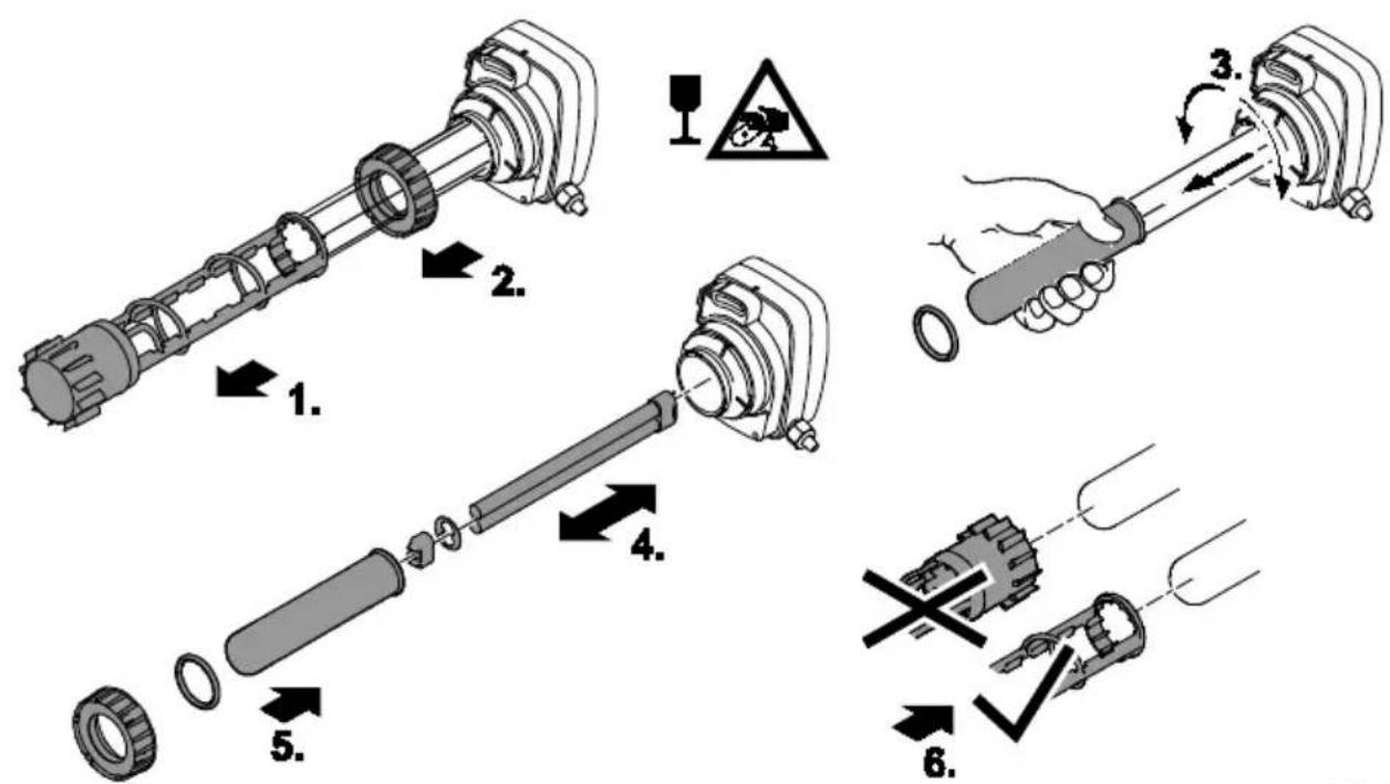
□ N
Remove the cleaning rotor.
Unscrew the clamping screw counterclockwise.
Remove the quartz glass including the O ring towards the front with a slight turning movement.
Pull out the UVC lamp and replace.
Carefully push the quartz glass including the O ring into the unit head up to the stop, fit the clamping screw and tighten up to the stop by turning clockwise.
– Clean the O ring, replace if damaged.
- Ensure that the O ring is located in the gap between the unit head and the quartz glass.
- EN -
Push the cleaning rotor onto the quartz glass.
- Ensure that it is correctly positioned.
Fit the unit head. ( Fitting the unit head)
Wear parts
• UVC lamp, quartz glass and O ring for quartz glass
- Cleaning rotor
Spare parts
The use of original parts from OASE ensures continued safe and reliable operation of the unit.
Please visit our website for spare parts drawings and spare parts.

www.oase-livingwater.com/spareparts
Storage/overwintering
The unit is protected from frost:
The unit can be operated as long as the water temperature does not go below +4 °C.
The unit is not protected from frost:
Take the unit out of operation at water temperatures below +8^ C or, at the latest, when freezing temperatures are to be expected.
- Drain the unit as far as possible, clean thoroughly and check for damage.
- Empty all hoses, pipes and connections as far as possible.
Disposal

NOTE
Do not dispose of this unit with domestic waste.
- Render the unit unusable beforehand by cutting the cables and dispose of the unit via the return system provided for this purpose.
Dispose of the UVC lamp by using the return system provided for this purpose.

www.oase-livingwater.com/onderdelen
Opslag/overwinteren

www.oase-livingwater.com/spareparts_INT
Armazenar/Invernar
O aparelho está num lugar protegido contra a geada:

www.oase-livingwater.com/spareparts_INT

www.oase-livingwater.com/spareparts_INT
Opbevaring/overvintring

www.oase-livingwater.com/spareparts_INT
Lagring/overvintring
Apparatet står beskyttet mot frost:
www.oase-livingwater.com/spareparts_INT

www.oase-livingwater.com/spareparts_INT
www.oase-livingwater.com/nahradnidily
Uložení/zazimování

www.oase-livingwater.com/spareparts_INT
Uloženie/prezimovanie

www.oase-livingwater.com/spareparts_INT

www.oase-livingwater.com/spareparts_INT

www.oase-livingwater.com/spareparts_INT

www.oase-livingwater.com/spareparts_INT

www.oase-livingwater.com/spareparts_INT

www.oase-livingwater.com/spareparts_INT
存放/过冬
设备放置时,做防霜冻保护:
natural_image
Abstract line drawing of a teardrop shape with curved lines (no text or symbols)
- BITRON C UVC
- Translation of the original Operating Instructions
- WARNING
- Safety information
- Electrical connection
- Safe operation
- - EN -
- Information about this operating manual
- Symbols used in these instructions
- Warnings
- NOTE
- Additional information
- Product Description
- Intended use
- Installation and connection
- Operation with pool water or salt water
- Distances to be adhered to
- Solo operation
- Connecting the inlet
- Connecting the outlet
- Connect the unit to the flow-through filter.
- ProfiClear Premium / ProfiClear Classic / BioSmart
- BioTec ScreenMatic
- Commissioning/start-up
- Prerequisite
- Switching ON/switching OFF
- Check the function.
- Setting the bypass
- Maintenance and cleaning
- CAUTION
- Dismantling the unit head
- Fitting the unit head
- Cleaning the quartz glass
- Replacing the UVC lamp
- Wear parts
- Spare parts
- Storage/overwintering
- The unit is protected from frost:
- The unit is not protected from frost:
- Disposal
- Opslag/overwinteren
- Armazenar/Invernar
- Opbevaring/overvintring
- Lagring/overvintring
- Apparatet står beskyttet mot frost:
- Uložení/zazimování
- Uloženie/prezimovanie
- 存放/过冬
Brand : OASE
Model : Bitron C 72
Category : Water filter