
RXM-300 - Binoculars BUSHNELL - Free user manual and instructions
Find the device manual for free RXM-300 BUSHNELL in PDF.

| Product type | Red dot sight |
| Brand | Bushnell |
| Model | RXM-300 |
| Magnification | 1x |
| Reticle | 3 MOA dot |
| Total elevation/wind adjustment | 100/100 MOA |
| Click value | 1.0 MOA |
| Parallax-free distance | Unlimited |
| Number of brightness levels | 12 |
| Eye relief | Unlimited |
| Waterproof | Yes, IPX7 |
| Length | 2.0 inches (51 mm) |
| Weight (with mount) | 56.7 g (2.9 oz) |
| Power source | CR2032 lithium battery |
| Battery life | Over 35,000 hours (at medium brightness) |
| Key features | Shake-Awake (motion activation), automatic brightness control (LSC), lockout function (LOF) |
| Mounting | Direct on RMR/SRO footprint or on Picatinny/Weaver rail with compact mount and high spacer |
| Included accessories | Protection cap, battery cover with adjustment tool, CR2032 battery, Torx T15 key, mounting screws (3 types), cleaning cloth |
| Maintenance and cleaning | Use a microfiber cloth or optical paper; do not touch lenses with fingers |
| Safety | Never look at the sun through the sight; keep batteries away from children |
| Repairability | Contact Bushnell customer service for any electronic issues |
| Warranty | Bushnell Ironclad Warranty (see official website) |
Frequently Asked Questions - RXM-300 BUSHNELL
User questions about RXM-300 BUSHNELL
0 question about this device. Answer the ones you know or ask your own.
Ask a new question about this device
Download the instructions for your Binoculars in PDF format for free! Find your manual RXM-300 - BUSHNELL and take your electronic device back in hand. On this page are published all the documents necessary for the use of your device. RXM-300 by BUSHNELL.
USER MANUAL RXM-300 BUSHNELL
MOUNTING REFERENCE 4
MOUNTING DETAILS - DIRECT APPLICATIONS 4
MOUNTING DETAILS - ACCESSORY BASE RAILS :
RED DOT LENS POSITIONING 5
CORNER SPEED HOLES 5
INSTALLING THE BATTERY 5
SWITCHING POWER ON/OFF 5
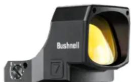
You've made the right decision by choosing the Bushnell RXM-300 Red Dot Reflex Sight!
The Bushnell RXM-300 is engineered with performance attributes and versatile mounting solutions for various small arms such as pistols, rifles, and shotguns, whether for plinking, competition, hunting, or home defense. The RXM-300 is powered by a long-lasting CR2032 lithium-metal battery with over 35,000 hours of battery life (at a brightness level of "6"). In addition, it delivers a crisp 4 MOA dot with 12 brightness levels and push-button operation in a compact package. Other optional features that may be utilized in any desired combination include shake-awake technology, auto-ambient reticle brightness control, and button lockout.
Note: battery life as listed will vary depending on the brightness settings used (stated life estimate is based on a typical, medium brightness setting), freshness and quality of the battery, ambient temperature, and other factors.
Your sight's illuminated reticle has been pre-focused, so the aiming point always appears in focus on the target. By comparison, open sights do not allow for easy or adequate focusing because three objects (rear sight, front sight, and target) have different focal lengths, resulting in a compromised focus.
The RXM-300 can be easily used with both eyes open (eye relief is unlimited), increasing the shooter's awareness of the surrounding environment and providing faster target acquisition due to the parallax free design, as the dot follows the movement of the user's eye while remaining fixed on the target. In addition, the sight is engineered for greater speed and accuracy and allows focus on the target rather than a reticle, thus increasing accuracy.
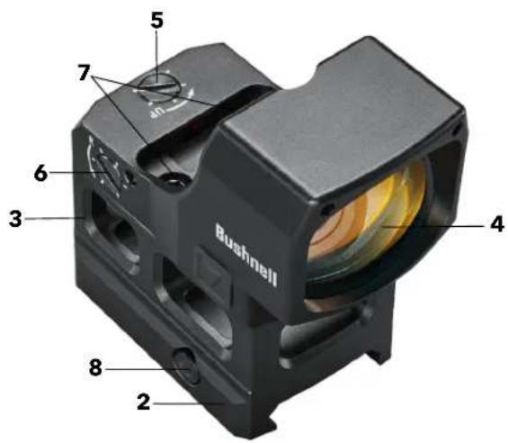
PARTS GUIDE
- Battery Compartment Cover
- Low-Profile Mount
- High-Rise Spacer
- Lens
- Elevation Adjustment
- Windage Adjustment
- Hold-Down Fasteners
- Mount Cross-Bolt Screw
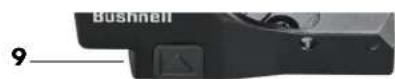
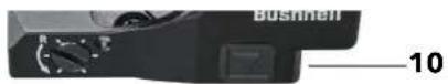
- Brightness Up Button
- Brightness Down Button
Note: Remove the plastic disc under the button battery before first use.
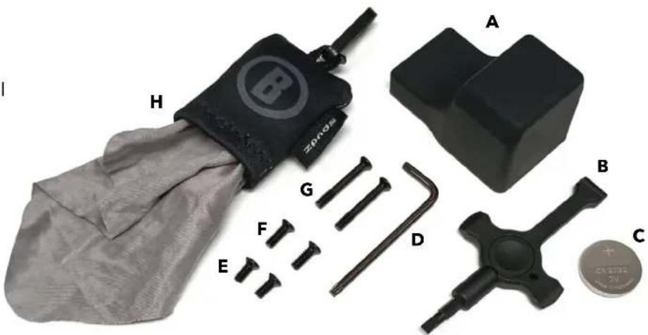
Product accessories included:
A. Protective Cover
B. Battery Door & W/E Adjustment Tool
C. CR2032 Battery
D. T15 Torx L-Key
E. Type A: 6-32 UNC 9.8mm long
F. Type B: 6-32 UNC 11.8mm long
G.Type C: 6-32 UNC 25.5mm long
H. Spudz Cleaning Cloth
WARNING: NEVER LOOK AT THE SUN THROUGH THE RED DOT REFLEX SIGHT (OR ANY OTHER OPTICAL INSTRUMENT). IT MAY PERMANENTLY DAMAGE YOUR EYES.
MOUNTING YOUR RXM-300 SIGHT

WARNING! BEFORE HANDLING YOUR FIREARM, BE SURE THE ACTION IS OPEN, THE CLIP OR MAGAZINE IS REMOVED, AND A ROUND IS NOT IN THE CHAMBER. DO NOT ATTEMPT ANY WORK UNTIL THE FIREARM HAS BEEN CLEARD AND DETERMINED TO BE SAFE.

WARNING! DEPENDING ON THE APPLICATION, IF THE SIGHT IS NOT MOUNTED FAR ENOUGH FORWARD, ITS REARWARD MOTION MAY INJURE THE SHOOTER WHEN THE FIREARM RECOILS.
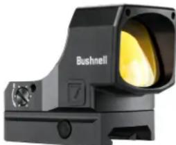
Even with its technologically advanced design and features, your new sight will only perform at its best if properly mounted. One of the most important contributing factors to the accuracy of your firearm and sight combination is the quality of the mount and the care taken during its installation. The RXM-300 will fit nearly all bases compatible with Trijicon®, RMR®, or SRO® sights. It also includes a low-profile mount and high-rise spacer for use with Weaver or Picatinny style accessory rails. Ensure your base is manufactured specifically for your pistol, rifle, or shotgun. Ensure your base is manufactured for your pistol, rifle, or shotgun.
MOUNTING REFERENCE
- Low-Strength thread-locker is acceptable for rifle or shotgun applications. Example: LOCTITE® 242™
-
Medium-Strength thread-locker is recommended for direct mount pistol applications. Example: LOCTITE® 243™
-
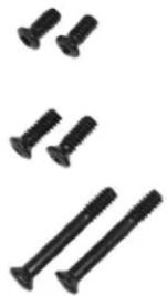
Type A: 6-32 UNC 9.8mm long
Use for direct mount applications with shallow tapped holes.
Screws protrude from the sight base approximately 2.4mm
- Type B: 6-32 UNC 11.8mm long
Use with mount or for direct mount applications with deeper tapped holes.
Screws protrude from the sight base approximately 4.4mm
- Type C: 6-32 UNC 25.5mm long
Use with mount and high-rise spacer.
MOUNTING DETAILS - DIRECT APPLICATIONS
The included hold-down mounting screws (two different pairs) are intended to be used with indirect mounting adapter plates like those used for GLOCK® MOS or direct mount applications. Be sure the screws do not bottom out or interfere with internal components. There are other types of optics-ready plate systems from pistol manufacturers (e.g., TAURUST™, T.O.R.O.) that utilize a pass-through plate system, which requires the user to utilize screws provided by the pistol manufacturer. If so, additional care must be taken to ensure the red dot sight is adequately clamped. Some screws may bottom out into the slide and seem tight but are not adequately clamping the sight onto the slide. The potential resulting looseness can cause lens fracture and potential risk to the user. Always follow user-manual guidance and/or seek assistance from the respective manufacturers or a qualified gunsmith. Always wear approved eye protection.
Any rail or base should create a uniform horizontal and vertical mounting platform. Be sure the base is properly installed and securely fastened according to the manufacturer's instructions for your safety. There is no set eye-relief for your RXM-300; therefore, you should provide at least three inches of clearance between the rear of the sight and your face when in any shooting position. Some firearm applications may have elevated recoil that may require additional clearance.
If mounting the sight without the included mounts and instead directly to an adapter plate (common for optics ready pistols), follow the manufacturer's instructions for attaching the adapter plate. Unless otherwise specified by the 3rd party manufacturer, remove any clearance by gently forward loading the plate during fastening. When attaching the red dot sight to the adapter plate, gently load the sight body forward while fastening. This action removes clearances that may otherwise shift under recoil and improves the chances of repeatable mounting should the red dot sight need to be removed for any reason, such as maintenance.
RXM-300 direct mount RMR®/SRO® footprint
GLOCK* and MOS are registered trademarks of GLOCK, Inc.
TAURUS™ and T.O.R.O. are registered trademarks of TIMI, taurususa.com
MOUNTING DETAILS - ACCESSORY BASE RAILS
- Loosen the side screw (aka cross-bolt) using the provided tool (T15 Torx L-key), so the locking bar can clamp around the Picatinny or Weaver style rail.
- Install the mount to the firearm rail by tightening the screw. First, ensure the sight is correctly positioned and the screw fits into the Picatinny or Weaver style rail slot. Next, forward load the mount while tightening the clamp screw until resistance is felt. Ensure the mount is seated flat and parallel to the accessory rail.
- Tighten the clamp fastener to 25 ± 2 Ibf*in with a torque wrench/driver. If a torque wrench is unavailable, use the provided T15 Torx L-key with the short leg inserted into the hex socket and tighten until the long leg elastically deforms/bends slightly. Note that the hex key should not bend permanently but only slightly while applying pressure.
CAUTION: Do not overtighten.
- Apply thread-locking compound per manufacturer's instructions to the Type B screws. Install fasteners and evenly tighten to 15-18 lbf*in.
NOTE: The high-rise spacer is needed for applications with a high cheek-weld (e.g., AR/MSR).
Place the high-rise spacer on top of the mount with the two thru-holes towards the rear to align with the mount. Substitute with the Type C screws and refer to the step #4 tightening instructions.
CAUTION: Do not overtighten.
RXM-300 with low-profile mount for accessory rails
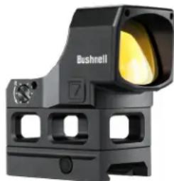
RXM-300 with high rise spacer. AR/MSR & some S/G models.
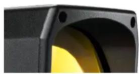
RED DOT LENS POSITIONING
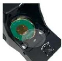
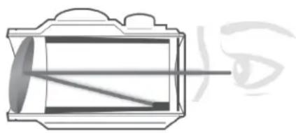
All red dot sights have a spherical objective lens at the front of the unit. However, unlike a conventional riflescope with all lenses mounted perpendicular (at a 90 degree angle) to the axis of the tube, the objective lens in a red dot sight is positioned off the axis. As a result, it appears to be tilted when looking at the sight (right). This angle of the front lens allows the light generated by the battery powered LED light source inside the unit to be reflected into the sight. The reflected light becomes the "dot" or aiming reference that the shooter sees when a red dot sight is switched on. This engineered "bending" of light makes today's red-dot sights popular and easy to use.
CORNER SPEED HOLES
The corner speed holes' primary intention is to serve as crumple zones for severe impacts to protect the lens. However, they also serve as quick alignment references during pistol presentations, useful for training or high stress scenarios.
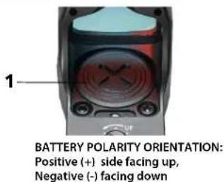
INSTALLING THE BATTERY
Before powering on your sight for the first time, you must activate the installed CR2032 lithium battery by removing the protective plastic disc isolating the battery. Use the flat plastic end of the included black multi-tool to unscrew the battery compartment cover and remove the plastic disc located under the battery. Alternatively, the battery may be found as a separate insert within child-resistant packaging. If so, remove the battery from the secondary packaging, then install it into the battery compartment. See the Parts Guide for the location of the battery compartment. CAUTION: Improper installation of the battery may damage the internal contacts. Ensure that the positive (+) side faces up and the negative (-) side is down. Replace the battery cover. Verify that the red dot is on and functional by switching the power on and increasing the brightness if necessary (see "Switching Power On/Off" and "Adjusting Dot Brightness" below).
Should your reticle grow dim or not light, replace the battery, following the installation procedure described above.
SWITCHING POWER ON/OFF
- When installing a battery, the unit should automatically turn on.
- To turn the power off, press and hold the DOWN button for 3 seconds.
- To turn the unit back on, press either the UP or DOWN button and the red dot (reticle) will appear.
- The previously selected brightness level and operating modes will resume. It may be necessary to turn the brightness up depending on the last setting at the time of power down.
NOTE: Any time the battery is replaced, the unit will resume in the default mode, which is Manual Brightness Control with Shake-Awake engaged.
To adjust the intensity level of the dot reticle, press the Brightness UP button to increase the brightness or the Brightness DOWN button to decrease brightness. The RXM-300 provides 12 levels of brightness from the dimmest to the brightest setting. Every single press of the UP or DOWN button will increase or decrease the brightness by one level. The highest two settings are visible even in bright daylight conditions. Please note that the highest settings are often too bright for indoor or dark ambient conditions and will produce some stray reflections from the LED package. This is normal; if experienced, the brightness should be reduced to compensate.
Note: Manual Control (MC) is the default state for brightness adjustment.
SHAKE AWAKE (SA) FEATURE
Bushnell's RXM-300 is equipped with a shake awake feature. This feature allows the user to save on battery usage by putting the sight into standby mode while the firearm is undisturbed for approximately five minutes. If the sight is in standby mode, move the firearm to "wake up" or reengage the sight. The red dot will be visible again.
Shake awake (SA) is the default operating status. To disable for traditional, manual operation:
- Press and Hold the UP button for three seconds until the dot swells (dim to bright). This enters into light-sensing-control (LSC) mode.
- Again, Press and Hold the UP button for three seconds until the dot flashes six times. This indicates the sight is in the shake awake program initiation. After the six time blink initiation sequence, the sight will blink according to the active shake awake (SA) mode. If SA is on/active, the LED will blink on & off steadily. If SA is inactive, the LED blinks twice, pauses, and repeats.
- If the sight's LED is displaying the preferred mode (steady on-off blink for SA-ON or 2x blink, pause and repeat for SA-OFF), you may press and hold either the UP or DOWN button to confirm the selection and the sight will exit the SA mode change sequence and resume manual control (MC) mode. If you want to first change the SA mode, press the UP button and the LED blink pattern will change. Pressing the DOWN button will NOT cause a change; only pressing the UP button will cause the SA mode to change. NOTE: If no input is made for 5 minutes, the mode change sequence will time out, and the shake awake mode will remain unchanged. Return to Step #1 if a change is still desired.
LIGHT SENSING CONTROL (LSC) MODE
When engaged, Light Sensing Control (LSC) mode relies on local lighting conditions to automatically adjust the dot reticle brightness. It is limited to operate within the mid-range of the brightness settings otherwise available in the Manual Control (MC) mode.
- Press and Hold the UP button for three seconds; the red dot will swell (dim to bright) once. LSC mode is engaged.
- In LSC mode, press any button to exit, and the red dot will swell once, and the sight reenters Manual Control mode.
BUTTON LOCKOUT FUNCTION (LOF) MODE
The RXM-300 also offers a Button Lockout Function (LOF) mode. This feature may be engaged from either Manual Control or Light Sensing Control Mode and may be used to prevent accidental button presses from changing settings. Note that Shake Awake mode status will be retained. For example, if SA mode is engaged, it will continue to operate while the sight is in LOF mode. Conversely, if SA mode is disengaged, it will not operate while in LOF mode.
To engage Button LOF:
- Press and hold both UP and DOWN buttons simultaneously for three seconds. The red dot will swell twice to indicate LOF mode is engaged. While LOF mode is engaged, the sight will ignore all button presses except what is required to disengage.
- To disengage, Press and hold both UP and DOWN buttons simultaneously for three seconds and wait for the red dot to swell twice. LOF mode has been disengaged, and the sight will reengage the prior mode and respond to typical inputs. Then, the buttons will be functional again.
Initial sighting in of the RXM-300 can be done using a bore sighter per the manufacturer's directions or by visual bore sighting through a rifle's barrel with the bolt removed as follows, referencing a target at a 25 to 50 yard distance (7-15 yards for a pistol. An alternative for pistol mounted applications is to use the iron sights as reference for initial/rough dot alignment). Boresighting should be done at your local shooting range rather than at home due to safety concerns and the convenience of confirming final sight-in with live fire while you are there.
- With the sight mounted, support the firearm while considering recoil and safe practices. Next, switch on the sight's power and adjust the brightness until the dot is easily visible.
- Start by sighting along the barrel and aim at a target 25 to 50 yards away (7-15 yards for a pistol). Next, view through your RXM-300 sight and gently rotate the windage and/or elevation adjustments, using the supplied tool or brass case rim to align the red dot with the target as seen along the barrel. The adjustments are detented, with 1 MOA per click and 30 MOA per full revolution, 120 MOA total travel each.
- Once preliminary zeroing is complete; you are ready for live fire. First, fire a test shot to determine the point-of-impact of your firearm relative to your point-of-aim. If you are not hitting your point-of-aim (the target's center), adjust by turning the windage and/or elevation screw(s) in the direction you want the impact to move.
- Repeat step 3, making adjustments as needed, to align the point of impact with the point of aim.
- Once satisfied with the basic alignment, it is recommended to repeat Step #3 except using the center of a 3 or 5 shot group as the overall estimate for alignment confirmation.
OPERATION UNDER EXTREME CONDITIONS
- Extreme heat (moist or dry): No special procedures are required. Avoid storing in these conditions if possible.
- Extreme cold: Extreme low temperatures may shorten battery life. Avoid storing in this condition if possible.
- Coastal environment, sea spray, water, mud, and snow: Ensure that the battery cap is tight to maintain the seal before exposing the sight to sea spray, mud, or snow or before immersing the sight in the water. Keep lens covers closed when sight is not being used. Clean lenses with lens paper/cloth (see caution note below) and wipe the sight dry after exposure to water, sea spray, mud, or snow.
- Dust storms and sandstorms: Keep lens cover in place when sight is not used.
- Monitor black-oxide steel hardware for corrosion. It is recommended to maintain a light film of oil on hold-down hardware. If corrosion is observed, it can be mitigated with a typical CLP or other appropriate firearm maintenance chemicals.
CAUTION: Never clean the lenses with your fingers. Use lens paper or microfiber cloth. By doing this, it will avoid scratching the glass and coatings.
- Use a soft brush or "canned air" to remove loose debris (sand, grass, etc.) before using the lens paper or soft, clean microfiber cloth. Low-pressure water may be used if the optic is heavily soiled with mud.
TROUBLESHOOTING
Problem: Red Dot Does Not Appear
Possible Causes/Solutions:
- Discharged battery: Replace the battery with a new CR2032 lithium cell.
- Battery installed incorrectly: Remove and reinstall the battery, referring to the Parts Guide battery compartment image.
- Battery not making good contact: Clean contact surfaces and reinstall the battery.
- Other Electronic Issues: Contact Bushnell customer service.
Problem: Impossible To Zero
Possible Causes/Solutions:
- The adjustment screw is at its limit: Check the mount's alignment to the barrel.
- The impact point moves: Check mount and firearm rail (or carry handle) stability.
TECHNICAL SPECIFICATIONS
| SKU | Magnification | Reticle | Total Elevation /Windage Travel (MOA) | Windage/Elevation Click Value | Parallax Free Distance (Yds) | # of Brightness Settings | Field or View and Eye Relief | Shake Awake Feature | Waterproof | Length (inches) | Weight (oz) |
| RXM300 1x4 MOA RedDot 120/120 1.0 MOA A 50 12 Unlimited | Yes IPX7 2.2 2.0* | ||||||||||
- Weight listed is for bare sight and battery. Total weight with mount is 2.9oz. Total weight with mount and high-rise spacer is 3.5oz.
FCC Statement
This device complies with part 15 of the FCC Rules. Operation is subject to the following two conditions: (1) This device may not cause harmful interference, and (2) this device must accept any interference received, including interference that may cause undesired operation.
This equipment has been tested and found to comply with the limits for a Class B digital device, pursuant to Part 15 of the FCC Rules. These limits are designed to provide reasonable protection against harmful interference in a residential installation.
This equipment generates, uses and can radiate radio frequency energy and, if not installed and used in accordance with the instructions, may cause harmful interference to radio communications. However, there is no guarantee that interference will not occur in a particular installation.
If this equipment does cause harmful interference to radio or television reception, which can be determined by turning the equipment off and on, the user is encouraged to try to correct the interference by one or more of the following measures:
Reorient or relocate the receiving antenna.
- Increase the separation between the equipment and receiver.
Connect the equipment into an outlet on a circuit different from that to which the receiver is connected.
Consult the dealer or an experienced radio/TV technician for help.
Shielded interface cable must be used with the equipment in order to comply with the limits for a digital device pursuant to Subpart B of Part 15 of FCC Rules. Specifications and designs are subject to change without any notice or obligation on the part of the manufacturer.


WARNING
THIS PRODUCT CONTAINS A BUTTON BATTERY
If swallowed, a lithium button battery can cause severe or fatal injuries within 2 hours.
Keep batteries out of reach of children.
If you think batteries may have been swallowed or placed inside any part of the body, seek immediate medical attention.

WARNING: THIS PRODUCT USES A LITHIUM BASE BATTERY. LITHIUM BATTERIES CAN OVERHEAT AND CAUSE DAMAGE IF PHYSICALLY ABUSED. DO NOT USE BATTERIES THAT ARE DAMAGED OR SHOW SIGNS OF PHYSICAL WEAR.
Click to read the Bushnell Ironclad Warranty.

Disposal of Electric and Electronic Equipment
(Applicable in the EU and other European countries with separate collection systems)
This equipment contains electric and/or electronic parts and must therefore not be disposed of as normal household waste. Instead, it should be disposed at the respective collection points for recycling provided by the communities. For you, this is free of charge.
If the equipment contains exchangeable (rechargeable) batteries, these too must be removed before and, if necessary, in turn be disposed of according to the relevant regulations (see also the respective comments in this unit's instructions).
Further information about the subject is available at your community administration, your local waste collection company, or in the store where you purchased this equipment.
Industry Canada Statement :
This device complies with ISED's license-exempt RSSs. Operation is subject to the following two conditions: (1) This device may not cause harmful interference, and (2) this device must accept any interference received, including interference that may cause undesired operation.
Radiation Exposure Statement :
This device complies with the Industry Canada portable RF exposure limit set forth for an uncontrolled environment and is safe for the intended operation as described in this manual. Further RF exposure reduction can be achieved if the product can be kept as far as possible from the user's body or if the device is set to a lower output power if such function is available.
Causes possibles/Solutions :
Causes possibles/Solutions :
CE PRODUIT CONTIENT UNE PILE BOUTON
DIESES PRODUKT ENTHÄLT EINE KNOPFBATTERIE
When engaged, Light Sensing Control (LSC) mode relies on local lighting conditions to automatically adjust the dot reticle brightness. It is limited to operate within the mid-range of the brightness settings otherwise available in the Manual Control (MC) mode.
- Press and Hold the UP button for three seconds; the red dot will swell (dim to bright) once. LSC mode is engaged.
- In LSC mode, press any button to exit, and the red dot will swell once, and the sight reenters Manual Control mode.
MODALITA FUNZIONE BLOCCO DEI PULSANTI (LOF)
©2023 Bushnell Outdoor Products
Bushnell, TM, denote trademarks of Bushnell Outdoor Products
www.bushnell.com
9200 Cody, Overland Park, KS 66214

- You've made the right decision by choosing the Bushnell RXM-300 Red Dot Reflex Sight!
- PARTS GUIDE
- Product accessories included:
- MOUNTING YOUR RXM-300 SIGHT
- MOUNTING REFERENCE
- MOUNTING DETAILS - DIRECT APPLICATIONS
- MOUNTING DETAILS - ACCESSORY BASE RAILS
- CAUTION: Do not overtighten.
- RED DOT LENS POSITIONING
- CORNER SPEED HOLES
- INSTALLING THE BATTERY
- SWITCHING POWER ON/OFF
- SHAKE AWAKE (SA) FEATURE
- LIGHT SENSING CONTROL (LSC) MODE
- BUTTON LOCKOUT FUNCTION (LOF) MODE
- OPERATION UNDER EXTREME CONDITIONS
- TROUBLESHOOTING
- FCC Statement
- WARNING
- THIS PRODUCT CONTAINS A BUTTON BATTERY
- Click to read the Bushnell Ironclad Warranty.
- Disposal of Electric and Electronic Equipment
- (Applicable in the EU and other European countries with separate collection systems)
- Industry Canada Statement :
- Radiation Exposure Statement :
- CE PRODUIT CONTIENT UNE PILE BOUTON
- DIESES PRODUKT ENTHÄLT EINE KNOPFBATTERIE
- MODALITA FUNZIONE BLOCCO DEI PULSANTI (LOF)
Brand : BUSHNELL
Model : RXM-300
Category : Binoculars