
TRS-125 - Binoculars BUSHNELL - Free user manual and instructions
Find the device manual for free TRS-125 BUSHNELL in PDF.

| Product Type | Red dot sight for handguns, rifles, and shotguns |
| Brand | Bushnell |
| Model | TRS-125 |
| Magnification | 1x (non-magnifying) |
| Reticle | 3 MOA red dot |
| Brightness levels | 10 adjustable levels |
| Power source | CR2032 lithium battery (included) |
| Typical battery life | Over 15,000 hours at brightness level 5 |
| Eye relief | Unlimited (both eyes open use possible) |
| Adjustment range (elevation/windage) | 100 MOA / 100 MOA |
| Click value | 1 MOA per click |
| Parallax | Parallax-free (set at 100 yards) |
| Auto shut-off | 12 hours, user-selectable |
| Waterproof rating | IPX7 (submersible to 1 meter) |
| Mounting | Weaver or Picatinny rail (compact mount and riser block included) |
| Length | 2.8 inches (approx. 71 mm) |
| Weight (with compact mount) | 5.3 oz (approx. 150 g) |
| Weight (with riser block) | 6.6 oz (approx. 187 g) |
| Included accessories | Riser block, set of screws (long and short), Allen wrenches (2 mm and 3 mm), microfiber cloth, multi-tool |
| Maintenance | Clean optics with a suitable soft cloth; avoid finger contact |
| Safety | Never look at the sun through the sight; always verify the firearm is unloaded before handling |
Frequently Asked Questions - TRS-125 BUSHNELL
User questions about TRS-125 BUSHNELL
0 question about this device. Answer the ones you know or ask your own.
Ask a new question about this device
Download the instructions for your Binoculars in PDF format for free! Find your manual TRS-125 - BUSHNELL and take your electronic device back in hand. On this page are published all the documents necessary for the use of your device. TRS-125 by BUSHNELL.
USER MANUAL TRS-125 BUSHNELL
Congratulations on your purchase of the Bushnell TRS-125 Red Dot Reflex Sight!
The Bushnell TRS-125 is engineered especially for competitive shooting and target shooting or plinking with handguns, rifles, shotguns and bows, as well as hunting at shorter ranges. The TRS-125 is powered by a long-lasting CR2032 lithium-metal battery with more than 15,000 hours of battery life (at a brightness level of "5"). It delivers a bright, crisp 3 MOA dot with 10 brightness levels and push-button operation in a compact package.
Note: battery life as listed will vary depending on the brightness settings used (stated life estimate is based on a typical, medium brightness setting), freshness and quality of the battery, ambient temperature, and other factors.
Your sight's illuminated reticle has been pre-focused, so the aiming point always appears in focus on the target. By comparison, open sights do not allow for easy or adequate focusing because there are 3 objects (rear sight, front sight, and target) with different focal lengths, which results in a compromised focus.
The TRS-125 can be easily used with both eyes open (eye relief is unlimited), increasing the shooter's awareness of the surrounding environment and providing faster target acquisition due to the parallax free design, as the dot follows the movement of the user's eye while remaining fixed on the target. Engineered for greater speed and accuracy, these sights allow you to focus on the target rather than a reticle, thus increasing accuracy.
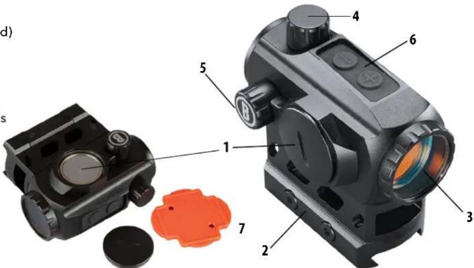
PARTS GUIDE
- Battery Compartment Cover
- Mount (Hi-Rise Spacer is pre-installed)
- Lens
- Capped Elevation Adjustment
- Capped Windage Adjustment
- Brightness & Timer Function Controls
- Multi-tool*
*The multi-tool is convenient for accessing battery compartment and adjusting windage or elevation turrets.
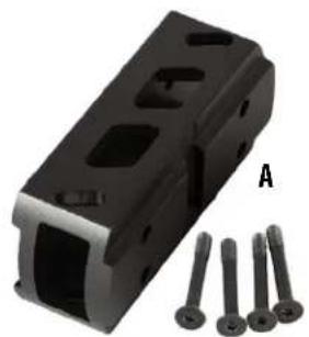
Product accessories included:
A. Hi-Rise Spacer (with Long Screw set and Low-Profile Mount)
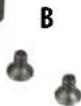
B. Short Screw set for Low-Profile Mount (direct to sight, no spacer option)
C. Small Hex Key (2mm)
D. Large Hex Key (3mm)
E. Microfiber Cleaning Cloth


WARNING: NEVER LOOK AT THE SUN THROUGH THE RED DOT REFLEX SIGHT (OR ANY OTHER OPTICAL INSTRUMENT). IT MAY PERMANENTLY DAMAGE YOUR EYES.
MOUNTING YOUR TRS-125 SIGHT

WARNING! BEFORE HANDLING YOUR FIREARM, BE SURE ACTION IS OPEN, CLIP OR MAGAZINE IS REMOVED AND A ROUND IS NOT IN THE CHAMBER. DO NOT ATTEMPT ANY WORK UNTIL THE FIREARM HAS BEEN CLEARED AND DETERMINED TO BE SAFE.
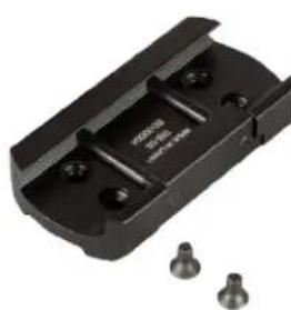
The TRS-125 sight includes a low-profile mount for Weaver style or Picatinny rails. It also comes with a high-rise spacer and longer screw set (installed) that is well-suited for MSR (flat-top receiver) applications. Should the user be mounting it on a firearm other than an MSR, they may wish to remove the high-rise spacer and attach just the low-profile mount with the provided short screw set (4 pcs).
The base or bases you use with your sight should be manufactured specifically for your pistol, rifle or shotgun and should create a uniform horizontal and vertical mounting platform. Be sure they are properly installed and securely fastened according to the manufacturer's instructions for your safety. There is no set eye relief for the TRS-125 sight; therefore, you should provide at least three inches of clearance between the viewing lens and your eye when in the shooting position. Note that firearms with adjustable length-of-pull ("LOP") buttstocks can affect or limit the amount of usable eye relief.
Set the mount onto the base or bases so that it aligns with the crosscut slots. Work the mount into the base until the cross-bolt seats into the slot. Forward load the mount, so that the cross-bolt engages the forward slot and clearance is removed. While holding the unit in position, securely tighten the locking nut or mounting plate. The next section of the manual provides some specific mounting details for the TRS-125 sight.
MOUNTING DETAILS
- Loosen the side screws (aka cross-bolts) by means of the provided tool (large 3mm hex L-key), so that the locking bar can clamp around the Picatinny or Weaver style rail.
- Install the sight to the firearm rail by tightening the screws. First, ensure that the sight is correctly positioned and that the screws fit into slots on the Picatinny or Weaver style rail. Forward load the optic and alternate tightening between the x2 side screws to remove clearance and avoid canting of the lock bar, respectively. Turn the screws until resistance is felt. Confirm mount is flat on rail and clamp is engaged. Alternate between each screw when tightening, to avoid canting the lock bar.
- Tighten both screws to 15-20 lbf*in with a torque wrench/driver. If a torque wrench is not available, use the provided 3mm hex key with the short leg inserted into the hex socket and tighten until the long leg elastically deforms/ bends slightly. Note that the hex key should not bend permanently, but only slightly while pressure is applied.
CAUTION: Do not overtighten.
To convert from the hi-rise spacer (pre-installed) to the low-profile mount (bottom section only):
- Using the provided small 2mm hex key (C), loosen the 4 long screws attaching the hi-rise spacer and low-profile mount to the sight, until the low-profile mount can be pulled away from the sight and spacer (A).
- Remove the long screws and set them aside, along with the hi-rise spacer. Store these for future use.
- Locate the included short screws (set of 4) and use them to fasten the low-profile mount directly to the sight, using the small 2mm hex key (B & C).
- Tighten the mount to the sight (alternating between the 4 screws) to a torque of 12-15 lbf*in.
CAUTION: Do not overtighten.
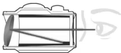
ABOUT RED DOT LENS POSITIONING
All red dot sights have an objective lens at the front of the unit that is spherical in shape. However, unlike a conventional riflescope with all lenses mounted perpendicular (at a 90 degree angle) to the axis of the tube, the objective lens in a red dot sight is positioned off axis and appears to be tilted when looking at the sight (right). This angle of the front lens allows the light generated by the battery powered LED light source inside the unit to be reflected into the sight. The reflected light becomes the "dot" or aiming reference that the shooter sees when a red dot sight is switched on. This engineered "bending" of light is what makes today's red-dot sights so popular and easy to use.
ACTIVATING THE BATTERY
Before powering on your sight for the first time, you will need to open the battery compartment using the supplied plastic multi-tool or a coin and remove the protective sticker or plastic disc from the battery. See the Parts Guide for the location of the battery compartment.
REPLACING THE BATTERY
Should your reticle grow dim or not light at all, replace the battery. To install a new battery, unscrew the round battery compartment cover using the supplied multi-tool or a coin. Insert a new CR2032 lithium-metal battery, noting the position of the positive and negative sides (positive side facing out, towards the cover). Replace battery cover.
CAUTION: When replacing the battery cover, be sure that the O-ring is present and not damaged. Failure to do so could result in water leakage into the battery compartment.
Verify that red dot is present by switching the power on and increasing the brightness if necessary (see next sections).
SWITCHING POWER ON/OFF AND USING THE 12 HR AUTO-OFF TIMER
To turn the sight's power on and off, press either the "plus" or "minus" button on the top of the sight. To switch power off, press and hold the "minus" button for 2.5 seconds. To change the auto-off timer mode, press and hold both plus and minus buttons for 2 seconds. When the timer is activated (indicated by 4 fast flashes of the red dot), power will automatically switch off after 12 hours to extend battery life if no button has been pressed. Switch power on again to continue using the sight if necessary. To turn the timer off, press and hold both buttons for 2 sec. again. When the timer is deactivated, the red dot will flash 3 times slowly.
Note: the default status of the timer is engaged. Each time the battery is depleted, removed and reinstalled or replaced, the unit will return to its default state. When the unit is on and the timer is activated, it will restart anytime a button is pressed and quickly released.
To adjust the brightness level of the dot reticle, press and release the "plus" button on the top of the sight to increase brightness. Press and release the "minus" button to decrease brightness. Once the high (or low) limit of brightness settings has been reached, if you continue to press the plus (or minus) button, the reticle will flash to indicate it cannot be further brightened (or dimmed). The preferred brightness setting is retained in memory and will resume after the unit has been turned off or automatically turns off. If the battery is depleted or removed, the default brightness will resume, which is setting 5 (middle of the total range of 10 settings).
- With the sight mounted, rest the firearm on a solid support. Switch on the sight's power and adjust brightness as needed until dot is easily visible.
- Remove the windage and elevation adjustment caps.
- Sight along the barrel and aim at a target 50 to 100 yards away. Sight through your TRS-125 Red Dot and turn the windage and/or elevation adjustments to align the center dot with the target as seen along the barrel. Each click of adjustment moves the point of impact by 1 MOA, which is approximately 1 in @ 100yd or 0.5 in @ 50yd. Once the sight is zeroed, replace the adjustment caps.
OPERATION UNDER EXTREME CONDITIONS
- Extreme heat (moist or dry): no special procedures required. Avoid prolonged exposure if possible.
- Extreme cold: extreme low temperature may shorten battery life.
- Coastal environment, sea spray, water, mud and snow: ensure that battery cap and the two adjustment caps (if present) are tightened before exposing the sight to sea spray, mud, snow or before immersing the sight in water. Hand tighten only. Keep lens covers closed when sight is not being used. Clean lenses with lens paper/cloth (see caution note below) and wipe the sight dry as soon as possible after exposure to water, sea spray, mud or snow.
- Dust storms and sandstorms: keep lens covers closed when sight is not being used.
- Monitor black-oxide, steel hardware for corrosion. It's recommended to maintain a light film of oil on all hardware and if corrosion is observed, it can be mitigated with a typical CLP or other firearm maintenance chemicals.
CAUTION: The lenses shall never be cleaned with fingers but with lens paper/cloth, to avoid scratching the glass.
Use a soft brush or "canned air" to remove any loose debris (sand, grass, etc.) prior to using the lens paper or soft, clean cloth.
TROUBLE SHOOTING
Problem: Red Dot Does Not Appear
Possible Causes/Solutions:
- Discharged battery: Replace battery with a new CR2032 lithium cell.
- Battery installed incorrectly: Remove and reinstall battery, referring to the Parts Guide battery compartment image.
- Battery not making good contact: Clean contact surfaces and reinstall battery.
- Other Electronic Issues: Contact Bushnell customer service.
Problem: Impossible To Zero
Possible Causes/Solutions:
- Adjustment screw is at its limit: Check alignment of mount to barrel.
- Impact point is moving: Check mount and firearm rail (or carry handle) stability.
TECHNICAL SPECIFICATIONS
| SKU | Magnification | Reticle | Total Elevation /Wind-age Travel (MOA) | Windage/Elevation Click Value | Parallax Free Distance (Yds) | # of Brightness Settings | Field or View and Eye Relief | User Selectable Timer | Waterproof | Length (inches) | Weight (oz.) |
| TRS125 1x3 MOA | Dot 100/100 1.0 MOA 100 10 | Unlimited Yes, 12 hr Yes, IPX7 2.8 | 5.3* |
- Weight with battery and low-profile mount. Weight with high-rise mount is 6.6 oz.
Click to read the Bushnell Ironclad Warranty.

FCC Statement
This device complies with part 15 of the FCC Rules. Operation is subject to the following two conditions: (1) This device may not cause harmful interference, and (2) this device must accept any interference received, including interference that may cause undesired operation.
This equipment has been tested and found to comply with the limits for a Class B digital device, pursuant to Part 15 of the FCC Rules. These limits are designed to provide reasonable protection against harmful interference in a residential installation.
This equipment generates, uses and can radiate radio frequency energy and, if not installed and used in accordance with the instructions, may cause harmful interference to radio communications. However, there is no guarantee that interference will not occur in a particular installation.
If this equipment does cause harmful interference to radio or television reception, which can be determined by turning the equipment off and on, the user is encouraged to try to correct the interference by one or more of the following measures:
- Reorient or relocate the receiving antenna.
- Increase the separation between the equipment and receiver.
- Connect the equipment into an outlet on a circuit different from that to which the receiver is connected.
- Consult the dealer or an experienced radio/TV technician for help.
Shielded interface cable must be used with the equipment in order to comply with the limits for a digital device pursuant to Subpart B of Part 15 of FCC Rules. Specifications and designs are subject to change without any notice or obligation on the part of the manufacturer.

Industry Canada Statement :
This device complies with ISED's license-exempt RSSs. Operation is subject to the following two conditions: (1) This device may not cause harmful interference, and (2) this device must accept any interference received, including interference that may cause undesired operation.
Radiation Exposure Statement :
This device complies with the Industry Canada portable RF exposure limit set forth for an uncontrolled environment and is safe for the intended operation as described in this manual. Further RF exposure reduction can be achieved if the product can be kept as far as possible from the user's body or if the device is set to a lower output power if such function is available.
Disposal of Electric and Electronic Equipment
(Applicable in the EU and other European countries with separate collection systems)
This equipment contains electric and/or electronic parts and must therefore not be disposed of as normal household waste. Instead, it should be disposed at the respective collection points for recycling provided by the communities. For you, this is free of charge.
If the equipment contains exchangeable (rechargeable) batteries, these too must be removed before and, if necessary, in turn be disposed of according to the relevant regulations (see also the respective comments in this unit's instructions).
Further information about the subject is available at your community administration, your local waste collection company, or in the store where you purchased this equipment.


WARNING: THIS PRODUCT USES A LITHIUM BASED BATTERY. LITHIUM BATTERIES CAN OVERHEAT AND CAUSE DAMAGE IF PHYSICALLY ABUSED. DO NOT USE BATTERIES THAT ARE DAMAGED OR SHOW SIGNS OF PHYSICAL WEAR.
FRANÇAIS
Causes possibles/Solutions :
Causes possibles/Solutions :
©2023 Bushnell Outdoor Products
Bushnell, TM, denote trademarks of Bushnell Outdoor Products
www.bushnell.com
9200 Cody, Overland Park, KS 66214

- Congratulations on your purchase of the Bushnell TRS-125 Red Dot Reflex Sight!
- Note: battery life as listed will vary depending on the brightness settings used (stated life estimate is based on a typical, medium brightness setting), freshness and quality of the battery, ambient temperature, and other factors.
- PARTS GUIDE
- Product accessories included:
- MOUNTING YOUR TRS-125 SIGHT
- WARNING! BEFORE HANDLING YOUR FIREARM, BE SURE ACTION IS OPEN, CLIP OR MAGAZINE IS REMOVED AND A ROUND IS NOT IN THE CHAMBER. DO NOT ATTEMPT ANY WORK UNTIL THE FIREARM HAS BEEN CLEARED AND DETERMINED TO BE SAFE.
- MOUNTING DETAILS
- CAUTION: Do not overtighten.
- ABOUT RED DOT LENS POSITIONING
- ACTIVATING THE BATTERY
- REPLACING THE BATTERY
- SWITCHING POWER ON/OFF AND USING THE 12 HR AUTO-OFF TIMER
- OPERATION UNDER EXTREME CONDITIONS
- CAUTION: The lenses shall never be cleaned with fingers but with lens paper/cloth, to avoid scratching the glass.
- TROUBLE SHOOTING
- FCC Statement
- Industry Canada Statement :
- Radiation Exposure Statement :
- Disposal of Electric and Electronic Equipment
- (Applicable in the EU and other European countries with separate collection systems)
- FRANÇAIS
Brand : BUSHNELL
Model : TRS-125
Category : Binoculars