Z170 EXTREME7+ - Motherboard ASROCK - Free user manual and instructions
Find the device manual for free Z170 EXTREME7+ ASROCK in PDF.

User questions about Z170 EXTREME7+ ASROCK
0 question about this device. Answer the ones you know or ask your own.
Ask a new question about this device
Download the instructions for your Motherboard in PDF format for free! Find your manual Z170 EXTREME7+ - ASROCK and take your electronic device back in hand. On this page are published all the documents necessary for the use of your device. Z170 EXTREME7+ by ASROCK.
USER MANUAL Z170 EXTREME7+ ASROCK
Copyright©2015 ASRock INC. All rights reserved.
Copyright Notice:
No part of this documentation may be reproduced, transcribed, transmitted, or translated in any language, in any form or by any means, except duplication of documentation by the purchaser for backup purpose, without written consent of ASRock Inc.
Products and corporate names appearing in this documentation may or may not be registered trademarks or copyrights of their respective companies, and are used only for identification or explanation and to the owners' benefit, without intent to infringe.
Disclaimer:
Specifications and information contained in this documentation are furnished for informational use only and subject to change without notice, and should not be constructed as a commitment by ASRock. ASRock assumes no responsibility for any errors or omissions that may appear in this documentation.
With respect to the contents of this documentation, ASRock does not provide warranty of any kind, either expressed or implied, including but not limited to the implied warranties or conditions of merchantability or fitness for a particular purpose.
In no event shall ASRock, its directors, officers, employees, or agents be liable for any indirect, special, incidental, or consequential damages (including damages for loss of profits, loss of business, loss of data, interruption of business and the like), even if ASRock has been advised of the possibility of such damages arising from any defect or error in the documentation or product.

This device complies with Part 15 of the FCC Rules. Operation is subject to the following two conditions:
(1) this device may not cause harmful interference, and
(2) this device must accept any interference received, including interference that may cause undesired operation.
CALIFORNIA, USA ONLY
The Lithium battery adopted on this motherboard contains Perchlorate, a toxic substance controlled in Perchlorate Best Management Practices (BMP) regulations passed by the California Legislature. When you discard the Lithium battery in California, USA, please follow the related regulations in advance.
"Perchlorate Material-special handling may apply, see www.dtsc.ca.gov/hazardouswaste/perchlorate"
ASRock Website: http://www.asrock.com

The terms HDMI ^™ and HDMI High-Definition Multimedia Interface, and the HDMI logo are trademarks or registered trademarks of HDMI Licensing LLC in the United States and other countries.

Manufactured under license under U.S. Patent Nos: 5,956,674; 5,974,380; 6,487,535; 7,003,467 & other U.S. and worldwide patents issued & pending. DTS, the Symbol, & DTS and the Symbol together is a registered trademark & DTS Connect, DTS Interactive, DTS Neo:PC are trademarks of DTS, Inc. Product includes software.
© DTS, Inc., All Rights Reserved.

Connect

Interactive

Neo:PC
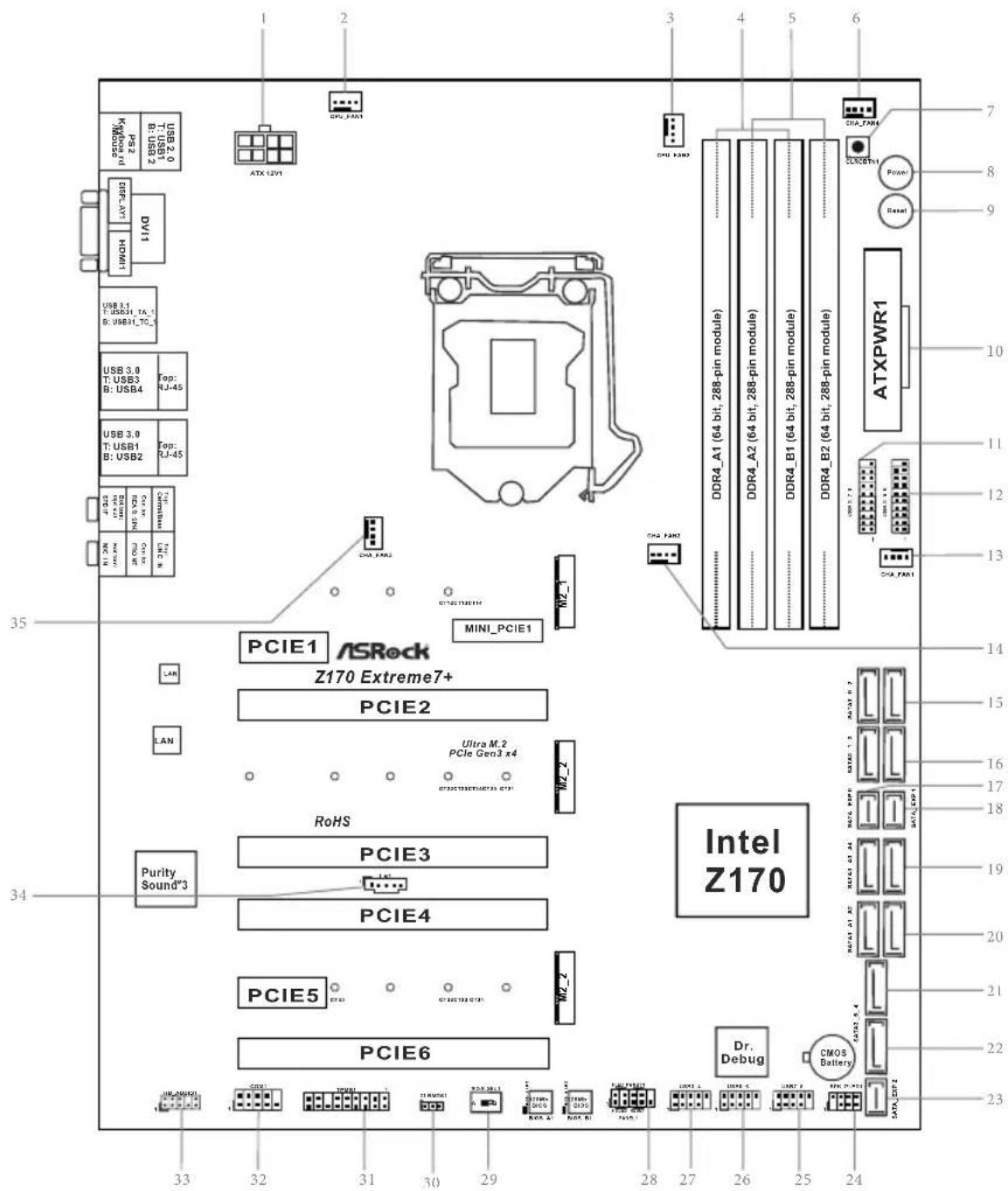
Motherboard Layout
text_image
PS2 USB 2.0 1.1 USB 3.0 8.1 USB 3.1 USB31_TA_1 B:USB31_TO_5 DVR1 HOMI USB 3.0 T:USB3 B:USB4 Top: RJ-45 USB 3.0 T:USB1 B:USB2 Top: RJ-45 N:ON M:ON M:ON M:ON M:ON PCIE1 ASRock Z170 Extreme7+ PCIE2 Ultra M.2 PCIe Gen3 x4 ROHS Purity Sound"3 PCIE3 PCIE4 PCIE5 PCIE6 Dr. Debug CMOS Battery ATXPWR1 DDR4_A1 (64 bit, 288-pin module) DDR4_A2 (64 bit, 288-pin module) DDR4_B1 (64 bit, 288-pin module) DDR4_B2 (64 bit, 288-pin module) PCIA_FAN1 PCIA_FAN2 PCIA_FAN3 PCIA_FAN4 PCIA_FAN5 PCIA_FAN6 PCIA_FAN7 PCIA_FAN8 PCIA_FAN9 PCIA_FAN10 PCIA_FAN11 PCIA_FAN12 PCIA_FAN13 PCIA_FAN14 PCIA_FAN15 PCIA_FAN16 PCIA_FAN17 PCIA_FAN18 PCIA_FAN19 PCIA_FAN20 PCIA_FAN21 PCIA_FAN22 PCIA_FAN23 PCIA_FAN24 PCIA_FAN25 PCIA_FAN26 PCIA_FAN27 PCIA_FAN28 PCIA_FAN29 PCIA_FAN30 PCIA_FAN31 PCIA_FAN32 PCIA_FAN33 PCIA_FAN34 PCIA_FAN35 PCIA_FAN36 PCIA_FAN37 PCIA_FAN38 PCIA_FAN39 PCIA_FAN40 PCIA_FAN41 PCIA_FAN42 PCIA_FAN43 PCIA_FAN44 PCIA_FAN45 PCIA_FAN46 PCIA_FAN47 PCIA_FAN48 PCIA_FAN49 PCIA_FAN50 PCIA_FAN51 PCIA_FAN52 PCIA_FAN53 PCIA_FAN54 PCIA_FAN55 PCIA_FAN56 PCIA_FAN57 PCIA_FAN58 PCIA_FAN59 PCIA_FAN60 PCIA_FAN61 PCIA_FAN62 PCIA_FAN63 PCIA_FAN64 PCIA_FAN65 PCIA_FAN66 PCIA_FAN67 PCIA_FAN68 PCIA_FAN69 PCIA_FAN70No. Description
1 ATX 12V Power Connector (ATX12V1)
2 CPU Fan Connector (CPU_FAN1)
3 CPU Fan Connector (CPU_FAN2)
4 2 x 288-pin DDR4 DIMM Slots (DDR4_A1, DDR4_B1)
5 2 x 288-pin DDR4 DIMM Slots (DDR4_A2, DDR4_B2)
6 Chassis Fan Connector (CHA_FAN4)
7 Clear CMOS Button (CLRCBTN1)
8 Power Switch (PWRBTN1)
9 Reset Switch (RSTBTN1)
10 ATX Power Connector (ATXPWR1)
11 USB 3.0 Header (USB3_7_8)
12 USB 3.0 Header (USB3_5_6)
13 Chassis Fan Connector (CHA_FAN1)
14 Chassis Fan Connector (CHA_FAN2)
15 SATA3 Connectors (SATA3_0_2)
16 SATA3 Connectors (SATA3_1_3)
17 SATA Express Connector (SATA_EXP0)
18 SATA Express Connector (SATA_EXP1)
19 SATA3 Connectors (SATA3_A3_A4)
20 SATA3 Connectors (SATA3_A1_A2)
21 SATA3 Connector (SATA3_4)
22 SATA3 Connector (SATA3_5)
23 SATA Express Connector (SATA_EXP2)
24 Power LED and Speaker Header (SPK_PLED1)
25 USB 2.0 Header (USB7_8)
26 USB 2.0 Header (USB5_6)
27 USB 2.0 Header (USB3_4)
28 System Panel Header (PANEL1)
29 BIOS Selection Switch (BIOS_SEL1)
30 Clear CMOS Jumper (CLRMOS1)
31 TPM Header (TPMS1)
32 COM Port Header (COM1)
33 Front Panel Audio Header (HD_AUDIO1)
34 Thunderbolt AIC Connector (TB1)
35 Chassis Fan Connector (CHA_FAN3)
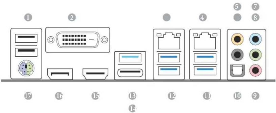
I/O Panel
text_image
1 2 3 4 5 6 7 8 9 10 11 12 13 14 15 16 17No. Description No. Description
1 USB 2.0 Ports (USB12) 10 Optical SPDIF Out Port
2 DVI-D Port 11 USB 3.0 Ports (USB3_12)
3 LAN RJ-45 Port (Intel ^ I219V) ^* 12 USB 3.0 Ports (USB3_34)
4 LAN RJ-45 Port (Intel® I211AT)* 13 USB 3.1 Type-A Port (USB31_TA_1)
5 Central / Bass (Orange) 14 USB 3.1 Type-C Port (USB31_TC_1)
6 Rear Speaker (Black) 15 HDMI Port
7 Line In (Light Blue) 16 DisplayPort 1.2
8 Front Speaker (Lime)** 17 PS/2 Mouse/Keyboard Port
9 Microphone (Pink)
* There are two LEDs on each LAN port. Please refer to the table below for the LAN port LED indications.
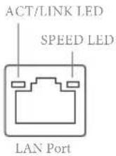
| Activity / Link LED Speed LED | |||
| Status Description Status Description | |||
| Off No Link Off | 10Mbps connection | ||
| Blinking | Data Activity | Orange | 100Mbps connection |
| On Link Green | Gbps connection | ||
** If you use a 2-channel speaker, please connect the speaker's plug into "Front Speaker Jack". See the table below for connection details in accordance with the type of speaker you use.
| Audio Output Channels | Front Speaker (No. 8) | Rear Speaker (No. 6) | Central / Bass (No. 5) | Line In (No. 7) |
| 2 V -- -- -- | ||||
| 4 V V -- -- | ||||
| 6 V V V -- | ||||
| 8 V V V V |

To enable Multi-Streaming, you need to connect a front panel audio cable to the front panel audio header. After restarting your computer, you will find the "Mixer" tool on your system. Please select "Mixer ToolBox", click "Enable playback multi-streaming", and click "ok". Choose "2CH", "4CH", "6CH", or "8CH" and then you are allowed to select "Realtek HDA Primary output" to use the Rear Speaker, Central/Bass, and Front Speaker, or select "Realtek HDA Audio 2nd output" to use the front panel audio.
ASRock Front USB 3.1 Panel
Specifications
| 75mm (W) x 42.8mm (H) x 148mm (L) | |
| ASMedia ASM1142 Controller | |
| Front Panel I/O | 1 x USB 3.1 Type-A Port (10 Gb/s) (Supports ESD Protection (ASRock Full Spik e Protection))* For charging Type-A USB devices, we suggest using the Type-A connectors on your motherboard.1 x USB 3.1 Type-C Port (10 Gb/s) (Supports ESD Protection (ASRock Full Spike Protection))* This port supports power outputs up to 5V/3A. For charging Type-C USB devices, the device should support Type-C standards to adjust the current because it will be different in Power On state (3 Amp) and Sleep state (1 Amp).* Some Type-C USB devices may only be charged by its own adapter. |
| Connector | 1 x SATA Express 10 Gb/s Connector1 x USB Power Connector |
| OS | Microsoft® Windows® 10 64-bit / 8.1 64-bit / 7 32-bit / 7 64-bit |
* It is recommended to install the ASRock Front USB 3.1 Panel into the drive bay of your chassis before connecting other USB devices.
ASRock Front USB 3.1 Panel Installation Guide
natural_image
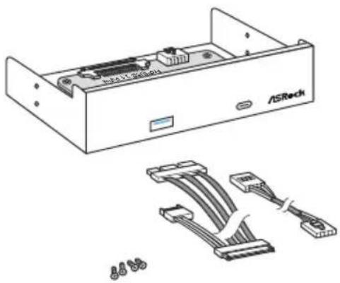
Technical line drawing of an ASRock internal unit with attached cable connectors (no text or symbols)Step 1
Prepare the bundled ASRock Front USB 3.1 Panel, SATA Express Cable, USB Power Cable and screws.
natural_image
Diagram of a USB flash drive installing a CD-ROM drive into an /ISRock chassis (no text or symbols on components)Step 2
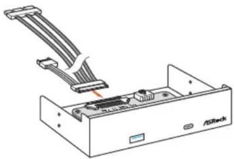
Connect one end of the SATA Express Cable to the SATA Express Connector on the ASRock Front USB 3.1 Panel.
natural_image
Diagram of an ASRock internal drive with cable connectors and a labeled base (no text or symbols beyond branding)Step 3
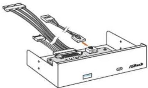
Connect one end of the USB Power Cable to the USB Power Connector on the ASRock Front USB 3.1 Panel.
natural_image
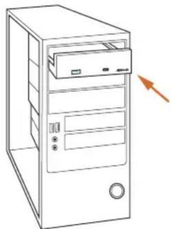
Line drawing of a desktop computer tower with an arrow pointing to the front panel (no text or symbols present)Step4
Install ASRock Front USB 3.1 Panel into the drive bay of the chassis.
natural_image
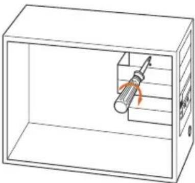
Line drawing of a screwdriver inside a transparent enclosure with internal structure (no text or symbols)Step 5
Screw ASRock Front USB 3.1 Panel to the drive bay with screws.
natural_image
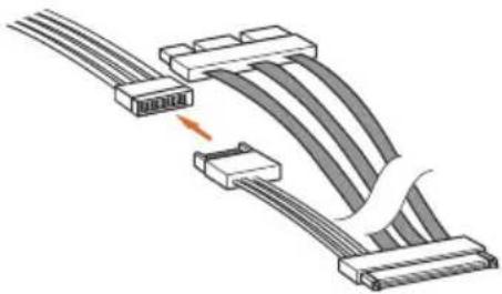
Diagram of a cable connector assembly with multiple connectors and a highlighted cable section (no text or symbols)Step 6
Connect the PSU's SATA Power Cable to the SATA Power Connector.
natural_image
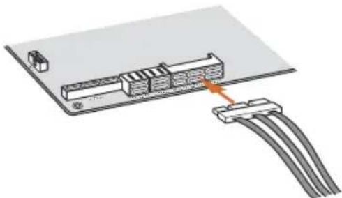
Diagram showing a connector with cable routing and a small device on top (no text or symbols)Step 7
Connect the other end of the SATA Express Cable to the SATA Express Connector on the motherboard.
natural_image
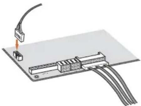
Diagram of a cable connector with an attached terminal block and cable routing (no text or symbols)Step 8
Connect the other end of the USB Power Cable to the USB 2.0 Header on the motherboard.
Chapter 1 Introduction
Thank you for purchasing ASRock Z170 Extreme7+ motherboard, a reliable motherboard produced under ASRock's consistently stringent quality control. It delivers excellent performance with robust design conforming to ASRock's commitment to quality and endurance.

Because the motherboard specifications and the BIOS software might be updated, the content of this documentation will be subject to change without notice. In case any modifications of this documentation occur, the updated version will be available on ASRock's website without further notice. If you require technical support related to this motherboard, please visit our website for specific information about the model you are using. You may find the latest VGA cards and CPU support list on ASRock's website as well. ASRock website http://www.asrock.com.
1.1 Package Contents
ASRock Z170 Extreme7+ Motherboard (ATX Form Factor)
ASRock Z170 Extreme7+ Quick Installation Guide
ASRock Z170 Extreme7+ Support CD
4 x Serial ATA (SATA) Data Cables (Optional)
1 x I/O Panel Shield
1 x ASRock SLI_Bridge_2S Card
3 x Screw for M.2 Sockets
1 x Screw for mini-PCIe Slot
1 x ASRock Front USB 3.1 Panel
4 x Screws for Front USB 3.1 Panel
1 x SATA Express Cable
1 x USB Power Cable
1.2 Specifications
| Platform | ATX Form FactorHigh Density Glass Fabric PCB |
| CPU | Supports 6^th Generation Intel ^ Core ^TM i7/i5/i3/Pentium ^ /Celeron ^ Processors (Socket 1151)Digi Power design12 Power Phase designSupports Intel ^ Turbo Boost 2.0 TechnologySupports Intel ^ K-Series unlocked CPUsSupports ASRock BCLK Full-range OverclockingSupports ASRock Hyper BCLK Engine |
| Chipset | Intel ^ Z170 |
| Memory | Dual Channel DDR4 Memory Technology4 x DDR4 DIMM SlotsSupports DDR4 3600+(OC) ^* /3200(OC)/2933(OC)/2800(OC)/2400(OC)/2133 non-ECC, un-buffered memory* Please refer to Memory Support List on ASRock's website for more information. (http://www.asrock.com/)Max. capacity of system memory: 64GBSupports Intel ^ Extreme Memory Profile (XMP) 2.015μ Gold Contact in DIMM Slots |
| Expansion Slot | 4 x PCI Express 3.0 x16 Slots (PCIE2/PCIE4/PCIE6: single at x16 (PCIE2); dual at x8 (PCIE2) / x8 (PCIE4); triple at x8 (PCIE2) / x8 (PCIE4) / x4 (PCIE6). PCIE3: x4 mode)1 x PCI Express 3.0 x1 Slot (PCIE5) (Flexible PCIe)1 x PCI Express 2.0 x1 Slot (PCIE1)1 x Half-size Mini-PCI Express SlotSupports AMD Quad CrossFireX ^TM , 3-Way CrossFireX ^TM and CrossFireX ^TM Supports NVIDIA ^ Quad SLI ^TM and SLI ^TM 15μ Gold Contact in VGA PCIe slot (PCIE2) |
| Graphics | Intel ^ HD Graphics Built-in Visuals and the VGA outputs can be supported only with processors which are GPU integrated. |
Supports Intel ^® HD Graphics Built-in Visuals : Intel ^® Quick
Sync Video with AVC, MVC (S3D) and MPEG-2 Full
HW Encode1, Intel ^® InTru ^TM 3D, Intel ^® Clear Video HD
Technology, Intel ^® Insider ^TM , Intel ^® HD Graphics 510/530
Pixel Shader 5.0, DirectX 12
Max. shared memory 1792MB
Three graphics output options: DVI-D, HDMI and
DisplayPort 1.2
Supports Triple Monitor
Supports HDMI with max. resolution up to 4K x 2K
(4096x2304) @ 24Hz
Supports DVI-D with max. resolution up to 1920x1200 @
60Hz
Supports DisplayPort 1.2 with max. resolution up to 4K x 2K
(4096x2304) @ 24Hz or 4K x 2K (3840x2160) @ 60Hz
Supports Auto Lip Sync, Deep Color (12bpc), xvYCC and
HBR (High Bit Rate Audio) with HDMI Port (Compliant
HDMI monitor is required)
Supports Accelerated Media Codecs: HEVC, VP8, VP9
Supports HDCP with DVI-D, HDMI and DisplayPort 1.2
Ports
Supports Full HD 1080p Blu-ray (BD) playback with DVI-D,
HDMI and DisplayPort 1.2 Ports
Audio
7.1 CH HD Audio with Content Protection (Realtek
ALC1150 Audio Codec)
Premium Blu-ray Audio support
Supports Surge Protection (ASRock Full Spike Protection)
Supports Purity Sound ^TM 3
- Nichicon Fine Gold Series Audio Caps
- 115dB SNR DAC with Differential Amplifier
- TI ^® NE5532 Premium Headset Amplifier (Supports up to
600 Ohms headsets)
- Pure Power-In
- Direct Drive Technology
- PCB Isolate Shielding
Supports DTS Connect
LAN
Gigabit LAN 10/100/1000 Mb/s
1 x Giga PHY Intel ^® I219V, 1 x GigaLAN Intel ^® I211AT
Supports Wake-On-LAN
Supports Lightning/ESD Protection (ASRock Full Spike Protection)
Supports Dual LAN with Teaming
Supports Energy Efficient Ethernet 802.3az
Supports PXE
Rear Panel
I/O
1 x PS/2 Mouse/Keyboard Port
1 x DVI-D Port
1 x HDMI Port
1 x DisplayPort 1.2
1 x Optical SPDIF Out Port
2 x USB 2.0 Ports (Supports ESD Protection (ASRock Full Spike Protection))
1 x USB 3.1 Type-A Port (10 Gb/s) (ASMedia ASM1142)
(Supports ESD Protection (ASRock Full Spike Protection))
1 x USB 3.1 Type-C Port (10 Gb/s) (ASMedia ASM1142)
(Supports ESD Protection (ASRock Full Spike Protection))
4 x USB 3.0 Ports (Intel® Z170) (Supports ESD Protection (ASRock Full Spike Protection))
2 x RJ-45 LAN Ports with LED (ACT/LINK LED and SPEED LED)
HD Audio Jacks: Rear Speaker / Central / Bass / Line in / Front Speaker / Microphone
ASRock
Front USB
3.1 Panel
1 x USB 3.1 Type-A Port (10 Gb/s) (Supports ESD Protection
(ASRock Full Spike Protection))
1 x USB 3.1 Type-C Port (10 Gb/s) (Supports ESD Protection
(ASRock Full Spike Protection))
Storage
6 x SATA3 6.0 Gb/s Connectors by Intel® Z170, support
RAID (RAID 0, RAID 1, RAID 5, RAID 10, Intel Rapid
Storage Technology 14 and Intel Smart Response
Technology), NCQ, AHCI and Hot Plug
4 x SATA3 6.0 Gb/s Connectors by ASMedia ASM1061, support NCQ, AHCI and Hot Plug
3 x SATA Express 10 Gb/s Connectors*
* Support to be announced
* M2_1, SATA3_0, SATA3_1 and SATA_EXP0 share lanes. If either one of them is in use, the others will be disabled.
* M2_2, SATA3_2, SATA3_3 and SATA_EXP1 share lanes. If either one of them is in use, the others will be disabled.
* M2_3, SATA3_4, SATA3_5 and SATA_EXP2 share lanes. If either one of them is in use, the others will be disabled.
3 x Ultra M.2 Sockets, support M.2 SATA3 6.0 Gb/s module and M.2 PCI Express module up to Gen3 x4 (32 Gb/s)
* Supports ASRock U.2 Kit
Connector
1 x COM Port Header
1 x TPM Header
1 x Power LED and Speaker Header
2 x CPU Fan Connectors (4-pin) (Smart Fan Speed Control)
4 x Chassis Fan Connectors (4-pin) (Smart Fan Speed Control)
1 x 24 pin ATX Power Connector
1 x 8 pin 12V Power Connector (Hi-Density Power Connector)
1 x Front Panel Audio Connector
1 x Thunderbolt AIC Connector
3 x USB 2.0 Headers (Support 6 USB 2.0 ports) (Supports ESD Protection (ASRock Full Spike Protection))
2 x USB 3.0 Headers (Support 4 USB 3.0 ports) (ASMedia
ASM1074 hub) (Supports ESD Protection (ASRock Full Spike Protection))
1 x Dr. Debug with LED
1 x Power Switch with LED
1 x Reset Switch with LED
1 x Clear CMOS Switch
1 x BIOS Selection Switch
BIOS
Feature
2 x 128Mb AMI UEFI Legal BIOS with multilingual GUI
support (1 x Main BIOS and 1 x Backup BIOS)
Supports Secure Backup UEFI Technology
ACPI 1.1 Compliant wake up events
SMBIOS 2.3.1 Support
CPU, GT_CPU, DRAM, VPPM, PCH 1.0V, VCCIO,
VCCPLL, VCCSA Voltage Multi-adjustment
Hardware Monitor
CPU/Chassis temperature sensing
CPU/Chassis Fan Tachometer
CPU/Chassis Quiet Fan (Auto adjust chassis fan speed by CPU temperature)
CPU/Chassis Fan multi-speed control
Voltage monitoring: +12V, +5V, +3.3V, CPU Vcore, GT_CPU, DRAM, VPPM, PCH 1.0V, VCCIO, VCCSA
os
Microsoft* Windows* 10 64-bit / 8.1 64-bit / 7 32-bit / 7 64-bit
* To install Windows® 7 OS, a modified installation disk with xHCI drivers packed into the ISO file is required. Please refer to page 183 for more detailed instructions.
* For the updated Windows® 10 driver, please visit ASRock's website for details: http://www.asrock.com
Certifications
FCC, CE, WHQL
ErP/EuP Ready (ErP/EuP ready power supply is required)
* For detailed product information, please visit our website: http://www.asrock.com

Please realize that there is a certain risk involved with overclocking, including adjusting the setting in the BIOS, applying Untied Overclocking Technology, or using third-party overclocking tools. Overclocking may affect your system's stability, or even cause damage to the components and devices of your system. It should be done at your own risk and expense. We are not responsible for possible damage caused by overclocking.
Chapter 2 Installation
This is an ATX form factor motherboard. Before you install the motherboard, study the configuration of your chassis to ensure that the motherboard fits into it.
Pre-installation Precautions
Take note of the following precautions before you install motherboard components or change any motherboard settings.
Make sure to unplug the power cord before installing or removing the motherboard components. Failure to do so may cause physical injuries and damages to motherboard components.
In order to avoid damage from static electricity to the motherboard's components, NEVER place your motherboard directly on a carpet. Also remember to use a grounded wrist strap or touch a safety grounded object before you handle the components.
Hold components by the edges and do not touch the ICs.
Whenever you uninstall any components, place them on a grounded anti-static pad or in the bag that comes with the components.
When placing screws to secure the motherboard to the chassis, please do not over-tighten the screws! Doing so may damage the motherboard.
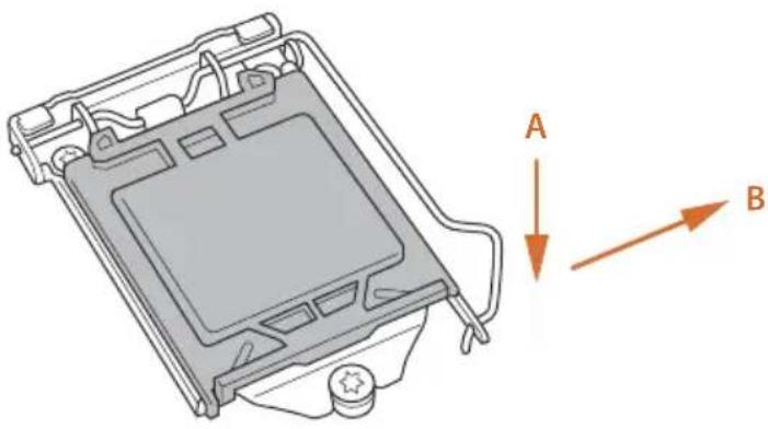
2.1 Installing the CPU

- Before you insert the 1151-Pin CPU into the socket, please check if the PnP cap is on the socket, if the CPU surface is unclean, or if there are any bent pins in the socket. Do not force to insert the CPU into the socket if above situation is found. Otherwise, the CPU will be seriously damaged.
- Unplug all power cables before installing the CPU.
1
natural_image
Technical line drawing of a mechanical component with labeled directional arrows (A and B), no readable text or symbols present.2
natural_image
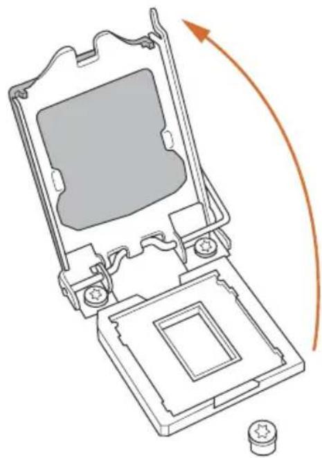
Technical line drawing of a mechanical device with an arrow indicating rotation or movement (no text or symbols present)3
natural_image
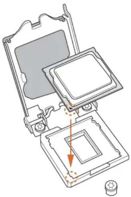
Technical diagram of a computer processor internal structure showing mounting holes and a highlighted slot (no text or symbols)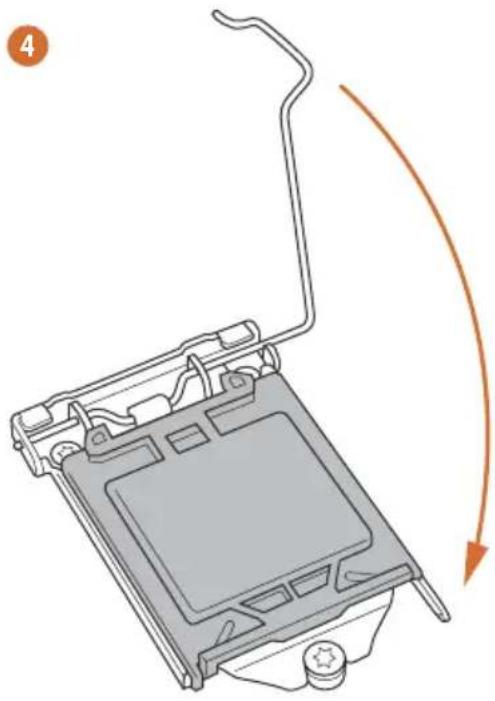
natural_image
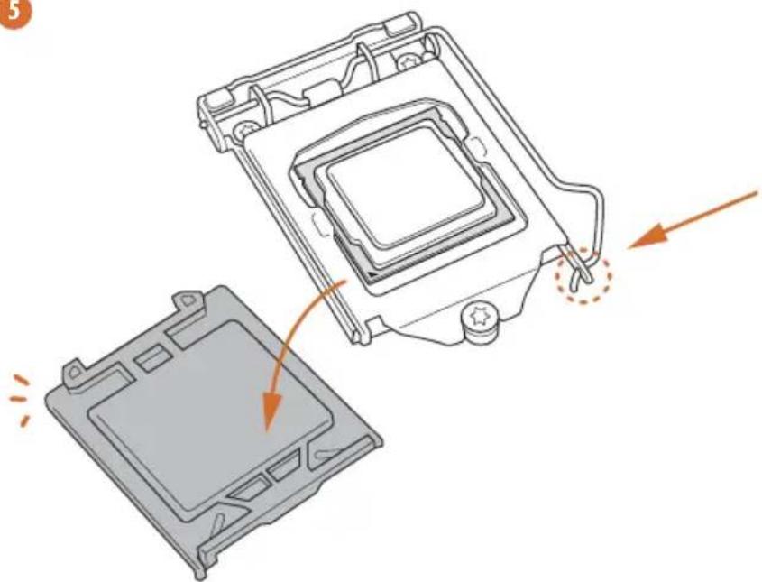
Diagram of a computer monitor with an orange curved arrow indicating motion (no text or symbols)5
natural_image
Diagram of a computer processor showing internal components and a close-up view of the base (no text or symbols)
Please save and replace the cover if the processor is removed. The cover must be placed if you wish to return the motherboard for after service.
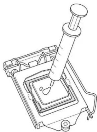
2.2 Installing the CPU Fan and Heatsink
natural_image
Technical line drawing of a mechanical assembly with a pipette inserted into a square component (no text or symbols)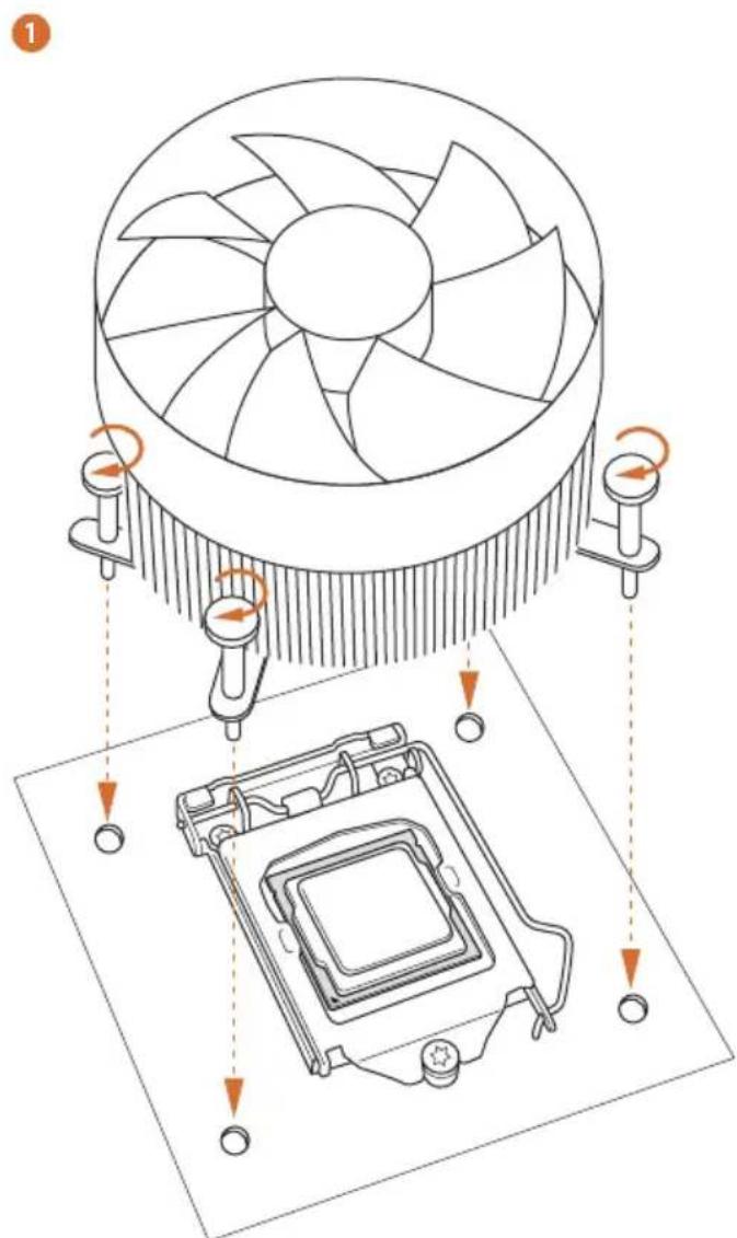
text_image
Technical diagram showing cooling fan installation and CPU socket assembly with directional arrows indicating rotation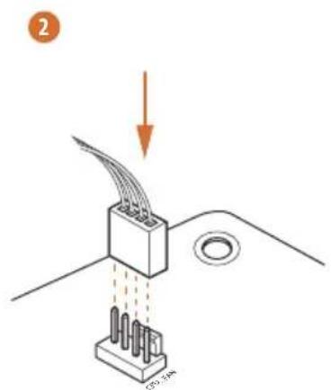
text_image
2 125.5mA2.3 Installing Memory Modules (DIMM)
This motherboard provides four 288-pin DDR4 (Double Data Rate 4) DIMM slots, and supports Dual Channel Memory Technology.

- For dual channel configuration, you always need to install identical (the same brand, speed, size and chip-type) DDR4 DIMM pairs.
- It is unable to activate Dual Channel Memory Technology with only one or three memory module installed.
- It is not allowed to install a DDR, DDR2 or DDR3 memory module into a DDR4 slot; otherwise, this motherboard and DIMM may be damaged.
Dual Channel Memory Configuration
Priority DDR4_A1 DDR4_A2 DDR4_B1 DDR4_B2
| 1 Populated Populated | |||
| 2 Populated Populated | |||
| 3 Populated Populated Populated Populated |

The DIMM only fits in one correct orientation. It will cause permanent damage to the motherboard and the DIMM if you force the DIMM into the slot at incorrect orientation.
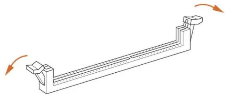
1
natural_image
Technical line drawing of a mechanical support structure with rotational arrows indicating motion (no text or symbols)2
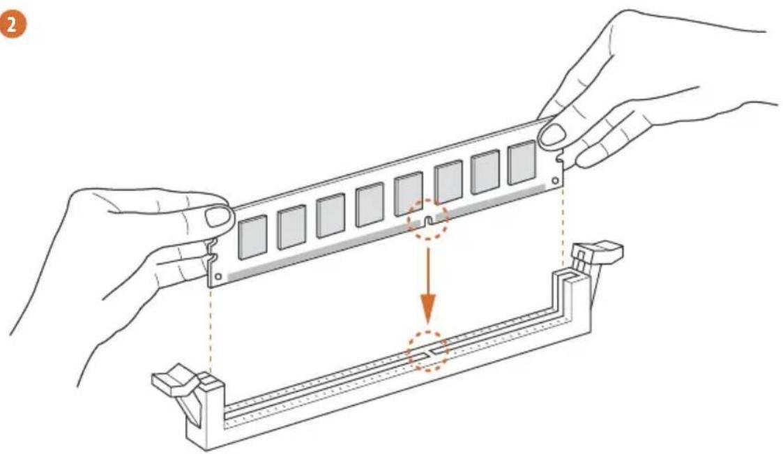
natural_image
Illustration of hands assembling a mechanical component with a highlighted section (no text or symbols)3
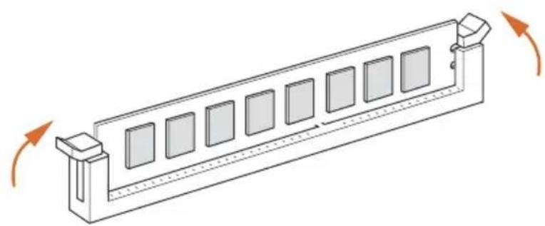
natural_image
Isometric line drawing of a rectangular mechanical component with multiple square cutouts and directional arrows indicating rotation (no text or symbols)2.4 Expansion Slots (PCI Express Slots)
There are 6 PCI Express slots and 1 mini-PCI Express slot on the motherboard.

Before installing an expansion card, please make sure that the power supply is switched off or the power cord is unplugged. Please read the documentation of the expansion card and make necessary hardware settings for the card before you start the installation.
PCIe slots:
PCIE1 (PCIe 2.0 x1 slot) is used for PCI Express x1 lane width cards.
PCIE2 (PCIe 3.0 x16 slot) is used for PCI Express x16 lane width graphics cards.
PCIE3 (PCIe 3.0 x16 slot) is used for PCI Express x4 lane width graphics cards.
PCIE4 (PCIe 3.0 x16 slot) is used for PCI Express x8 lane width graphics cards.
PCIE5 (PCIe 3.0 x1 slot) is used for PCI Express x1 lane width cards.
PCIE6 (PCIe 3.0 x16 slot) is used for PCI Express x4 lane width graphics cards.
mini-PCIe slot:
MINI_PCIE1 (mini-PCIe slot) is used for WiFi module.
PCIe Slot Configurations
| PCIE2 PCIE3 PCIE4 PCIE6 | |
| Single Graphics Card | x16 N/A N/A N/A |
| Two Graphics Cards in CrossFireXTM or SLITM Mode | x8 N/A x8 N/A |
| Three Graphics Cards in 3-Way CrossFireXTM Mode | x8 N/A x8 x4 |

For a better thermal environment, please connect a chassis fan to the motherboard's chassis fan connector (CHA_FAN1, CHA_FAN2, CHA_FAN3 or CHA_FAN4) when using multiple graphics cards.
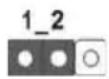
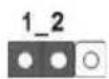
2.5 Jumpers Setup
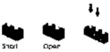
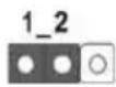
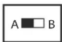
The illustration shows how jumpers are setup. When the jumper cap is placed on the pins, the jumper is “Short”. If no jumper cap is placed on the pins, the jumper is “Open”. The illustration shows a 3-pin jumper whose pin1 and pin2 are “Short” when a jumper cap is placed on these 2 pins.
text_image
Snail OpenClear CMOS Jumper (CLRMOS1)
(see p.1, No. 30)
Clear CMOSDefault
CLRMOS1 allows you to clear the data in CMOS. To clear and reset the system parameters to default setup, please turn off the computer and unplug the power cord from the power supply. After waiting for 15 seconds, use a jumper cap to short pin2 and pin3 on CLRMOS1 for 5 seconds. However, please do not clear the CMOS right after you update the BIOS. If you need to clear the CMOS when you just finish updating the BIOS, you must boot up the system first, and then shut it down before you do the clear-CMOS action. Please be noted that the password, date, time, and user default profile will be cleared only if the CMOS battery is removed.

The Clear CMOS Switch has the same function as the Clear CMOS jumper.
2.6 Onboard Headers and Connectors

Onboard headers and connectors are NOT jumpers. Do NOT place jumper caps over these headers and connectors. Placing jumper caps over the headers and connectors will cause permanent damage to the motherboard.
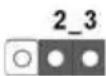
System Panel Header (9-pin PANEL1) (see p.1, No.28)
text_image
PLED+ PLED- PWRBTN# GND 1 GND RESET# GND HDLED- HDLED+Connect the power switch, reset switch and system status indicator on the chassis to this header according to the pin assignments below. Note the positive and negative pins before connecting the cables.

PWRBTN (Power Switch):
Connect to the power switch on the chassis front panel. You may configure the way to turn off your system using the power switch.
RESET (Reset Switch):
Connect to the reset switch on the chassis front panel. Press the reset switch to restart the computer if the computer freezes and fails to perform a normal restart.
PLED (System Power LED):
Connect to the power status indicator on the chassis front panel. The LED is on when the system is operating. 'The LED keeps blinking when the system is in S1/S3 sleep state.' The LED is off when the system is in S4 sleep state or powered off (S5).
HDLED (Hard Drive Activity LED):
Connect to the hard drive activity LED on the chassis front panel. The LED is on when the hard drive is reading or writing data.
The front panel design may differ by chassis. A front panel module mainly consists of power switch, reset switch, power LED, hard drive activity LED, speaker and etc. When connecting your chassis front panel module to this header, make sure the wire assignments and the pin assignments are matched correctly.
Power LED and Speaker
Header
(7-pin SPK_PLED1)
(see p.1, No. 24)
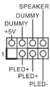
Please connect the chassis power LED and the chassis speaker to this header.
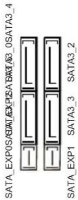
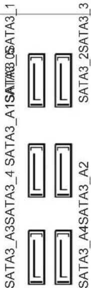
Serial ATA3 Connectors
(SATA3_0_2:
see p.1, No. 15)
(SATA3_1_3:
see p.1, No. 16)
(SATA3_4:
see p.1, No. 21)
(SATA3_5:
see p.1, No. 22)
(SATA3_A1_A2:
see p.1, No. 20)
(SATA3_A3_A4:
see p.1, No. 19)

text_image
SATA3_A3SATA3_4 SATA3_A1SATA3_0SATA3_1 SATA3_2SATA3_3 SATA3_A4SATA3_A2These ten SATA3 connectors support SATA data cables for internal storage devices with up to 6.0 Gb/s data transfer rate. The SATA3_0, SATA3_1 are shared with the SATA_EXP0. The SATA3_2, SATA3_3 are shared with the SATA_EXP1. The SATA3_4, SATA3_5 are shared with the SATA_EXP2. To minimize the boot time, use Intel® Z170 SATA ports (SATA3_0) for your bootable devices.
Serial ATA Express
Connectors
(SATA_EXP_0:
see p.1, No. 17)
(SATA_EXP_1:
see p.1, No. 18)
(SATA_EXP_2:
see p.1, No. 23)
text_image
SATA_EXP0:SATA_EXP1:SATA3_4 SATA_EXP1:SATA3_3:SATA3_2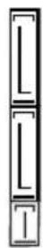
Please connect either
SATA or PCIe storage devices to these
connectors.
*SATA_EXP0 is shared with the SATA3_0,
SATA3_1 and the M2_1;
SATA_EXP1 is shared with the SATA3_2,
SATA3_3 and the M2_2; SATA_EXP2 is shared with the SATA3_4,
SATA3_5 and the M2_3.
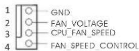
USB 2.0 Headers
(9-pin USB3_4)
(see p.1, No. 27)
(9-pin USB5_6)
(see p.1, No. 26)
(9-pin USB7_8)
(see p.1, No. 25)
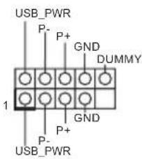
text_image
USB_PWR P- P+ GND DUMMY 1 GND P+ P- USB_PWRThere are three headers on this motherboard.
Each USB 2.0 header can support two ports.
USB 3.0 Headers
(19-pin USB3_5_6)
(see p.1, No. 12)
(19-pin USB3_7_8)
(see p.1, No. 11)
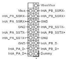
text_image
VbusVbus Vbus IntA_PB_SSRX- IntA_PB_SSRX+ GND GND IntA_PB_SSTX- IntA_PB_SSTX+ GND GND IntA_PB_D- IntA_PB_D+ Dummy 1Besides four USB 3.0 ports on the I/O panel, there are two headers on this motherboard. Each USB 3.0 header can support two ports.
Front Panel Audio Header
(9-pin HD_AUDIO1)
(see p.1, No. 33)
text_image
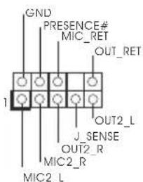
GND PRESENCE# MIC_RET OUT_RET 1 J_SENSE OUT2_R MIC2_R MIC2_LThis header is for connecting audio devices to the front audio panel.

- High Definition Audio supports Jack Sensing, but the panel wire on the chassis must support HDA to function correctly. Please follow the instructions in our manual and chassis manual to install your system.
- If you use an AC'97 audio panel, please install it to the front panel audio header by the steps below:
A. Connect Mic_IN (MIC) to MIC2_L.
B. Connect Audio_R (RIN) to OUT2_R and Audio_L (LIN) to OUT2_L.
C. Connect Ground (GND) to Ground (GND).
D. MIC_RET and OUT_RET are for the HD audio panel only. You don't need to connect them for the AC'97 audio panel.
E. To activate the front mic, go to the "FrontMic" Tab in the Realtek Control panel and adjust "Recording Volume".
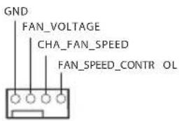
Chassis Fan Connectors
(4-pin CHA_FAN1)
(see p.1, No. 13)

text_image
FAN_SPEED_CONTROL CHA_FAN_SPEED FAN_VOLTAGE GNDPlease connect fan cables to the fan connectors and match the black wire to the ground pin.
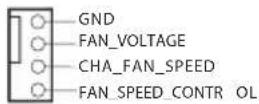
(4-pin CHA_FAN2)
(see p.1, No. 14)
text_image
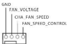
GND FAN_VOLTAGE CHA_FAN_SPEED FAN_SPEED_CONTR_OL(4-pin CHA_FAN3)
(see p.1, No. 35)
(4-pin CHA_FAN4)
(see p.1, No. 6)
CPU Fan Connectors
(4-pin CPU_FAN1)
(see p.1, No. 2)
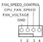
This motherboard provides a 4-Pin CPU fan (Quiet Fan) connector. If you plan to connect a 3-Pin CPU fan, please connect it to Pin 1-3.
(4-pin CPU_FAN2)
(see p.1, No. 3)
ATX Power Connector
(24-pin ATXPWR1)
(see p.1, No. 10)
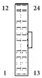
This motherboard provides a 24-pin ATX power connector. To use a 20-pin ATX power supply, please plug it along Pin 1 and Pin 13.
ATX 12V Power
Connector
(8-pin ATX12V1)
(see p.1, No. 1)
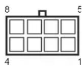
This motherboard provides an 8-pin ATX 12V power connector. To use a 4-pin ATX power supply, please plug it along Pin 1 and Pin 5.
Thunderbolt AIC
Connector
(5-pin TB1)
(see p.1, No. 34)
Please connect a Thunderbolt™ add-in card (AIC) to this connector via the GPIO cable.
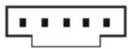
Serial Port Header
(9-pin COM1)
(see p.1, No. 32)
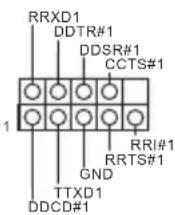
This COM1 header supports a serial port module.
TPM Header
(17-pin TPMS1)
(see p.1, No. 31)
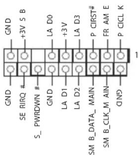
text_image
GND SE RIRQ # S_ PWRDWN # GND LA D0 +3V S B +3V LA D3 P CIRST# FR AM E P CICL K SM B_DATA_MAIN SM B_CLK_M_AIN GNDThis connector supports Trusted Platform Module (TPM) system, which can securely store keys, digital certificates, passwords, and data. A TPM system also helps enhance network security, protects digital identities, and ensures platform integrity.
2.7 Smart Switches
The motherboard has four smart switches: Power Switch, Reset Switch, Clear CMOS Switch and BIOS Selection Switch, allowing users to quickly turn on/off the system, reset the system, clear the CMOS values or switch between BIOS A and BIOS B.
Power Switch (PWRBTN) (see p.1, No. 8

Power Switch allows users to quickly turn on/off the system.
Reset Switch (RSTBTN) (see p.1, No. 9)

Reset Switch allows users to quickly reset the system.
Clear CMOS Switch (CLRCBTN) (see p.1, No. 7)
Clear CMOS Switch allows users to quickly clear the CMOS values.

This function is workable only when you power off your computer and unplug the power supply.
BIOS Selection Switch (BIOS_SEL1) (see p.1, No. 29
BIOS Selection Switch allows the system to boot from either BIOS A or BIOS B.

This motherboard has two BIOS chips, a primary BIOS (BIOS_A) and a backup BIOS (BIOS_B), which enhances the safety and stability of your system. Normally, the system will work on the primary BIOS. However, if the primary BIOS is corrupted or damaged, just flip the BIOS Selection Switch to "B", then the backup BIOS will take over on the next system boot. After that, use "Secure Backup UEFI" in the UEFI Setup Utility to duplicate a working copy of the BIOS files to the primary BIOS to ensure normal system operation. For safety issues, users are not able to update the backup BIOS manually. Users may refer to the BIOS LEDs (BIOS_A_LED or BIOS_B_LED) to identify which BIOS is currently activated.
2.8 Dr. Debug
Dr. Debug is used to provide code information, which makes troubleshooting even easier. Please see the diagrams below for reading the Dr. Debug codes.
Code Description
00 Please check if the CPU is installed correctly and then clear CMOS.
0d Problem related to memory, VGA card or other devices. Please clear CMOS, re-install the memory and VGA card, and remove other USB, PCI devices.
01 - 54 Problem related to memory. Please re-install the CPU and (except 0d), memory then clear CMOS. If the problem still exists, please install only one memory module or try using other memory modules. 5A-60
55 The Memory could not be detected. Please re-install the memory and CPU. If the problem still exists, please install only one memory module or try using other memory modules.
61 - 91 Chipset initialization error. Please press reset or clear CMOS.
92 - 99 Problem related to PCI-E devices. Please re-install PCI-E devices or try installing them in other slots. If the problem still exists, please remove all PCI-E devices or try using another VGA card.
A0 - A7 Problem related to IDE or SATA devices. Please re-install IDE and SATA devices. If the problem still exists, please clear CMOS and try removing all SATA devices.
b0 Problem related to memory. Please re-install the CPU and memory. If the problem still exists, please install only one memory module or try using other memory modules.
b4 Problem related to USB devices. Please try removing all USB devices.
b7 Problem related to memory. Please re-install the CPU and memory then clear CMOS. If the problem still exists, please install only one memory module or try using other memory modules.
d6 The VGA could not be recognized. Please clear CMOS and try re-installing the VGA card. If the problem still exists, please try installing the VGA card in other slots or use other VGA cards.
d7 The Keyboard and mouse could not be recognized. Please try re-installing the keyboard and mouse.
d8 Invalid Password.
FF Please check if the CPU is installed correctly and then clear CMOS.
2.9 M.2\_SSD (NGFF) Module Installation Guide
The M.2, also known as the Next Generation Form Factor (NGFF), is a small size and versatile card edge connector that aims to replace mPCIe and mSATA. The Ultra M.2 Sockets support M.2 PCI Express module up to Gen3 x4 (32 Gb/s).
* M2_1, SATA3_0, SATA3_1 and SATA_EXP0 share lanes. If either one of them is in use, the others will be disabled.
* M2_2, SATA3_2, SATA3_3 and SATA_EXP1 share lanes. If either one of them is in use, the others will be disabled.
* M2_3, SATA3_4, SATA3_5 and SATA_EXP2 share lanes. If either one of them is in use, the others will be disabled.
Installing the M.2\_SSD (NGFF) Module
natural_image
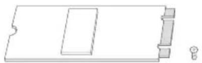
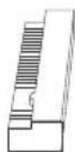
Pure technical line drawing of a rectangular component with internal cutouts and a small protrusion (no text or symbols)Step 1
Prepare a M.2_SSD (NGFF) module and the screw.
text_image
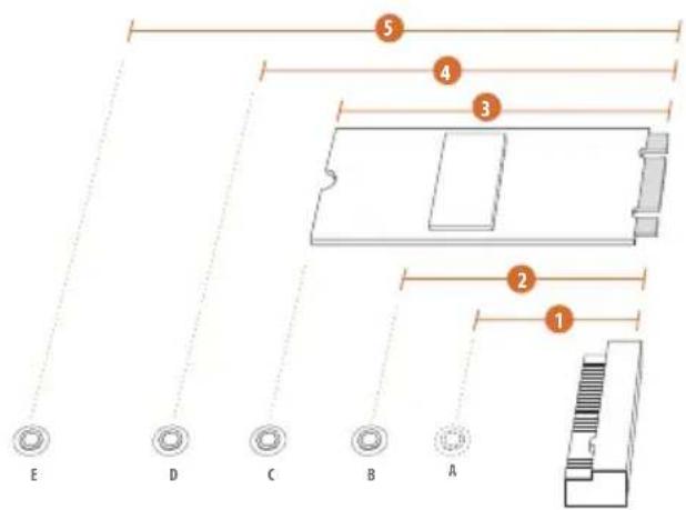
5 4 3 2 1 E D C B AStep 2
Depending on the PCB type and length of your M.2_SSD (NGFF) module, find the corresponding nut location to be used.
No. 1 2 3 4 5
| Nut Location A B C D E | |||||
| PCB Length | 3cm | 4.2cm | 6cm | 8cm | 11cm |
| Module Type | Type2230 | Type 2242 | Type2260 | Type 2280 | Type 22110 |
natural_image
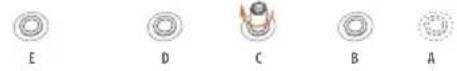
Five circular diagrams labeled A through E, showing different mechanical or structural configurations with no text or symbols.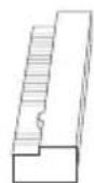
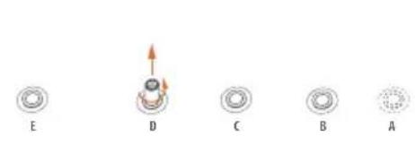
Step 3
Move the standoff based on the module type and length. The standoff is placed at the nut location D by default. Skip Step 3 and 4 and go straight to Step 5 if you are going to use the default nut. Otherwise, release the standoff by hand.
Step 4
Peel off the yellow protective film on the nut to be used. Hand tighten the standoff into the desired nut location on the motherboard.
text_image
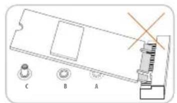
Diagram of a device with labeled components A, B, and C, showing a mechanical assembly with a cross mark indicating a specific part.Step 5
Align and gently insert the M.2 (NGFF) SSD module into the M.2 slot. Please be aware that the M.2 (NGFF) SSD module only fits in one orientation.

natural_image
Technical diagram of a mechanical component with labeled parts and an arrow indicating direction (no readable text or symbols)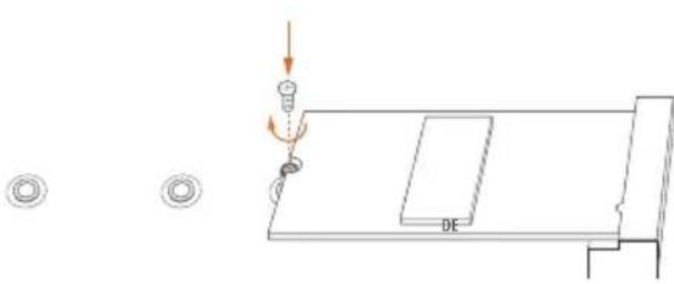
natural_image
Pure technical diagram showing a mechanical assembly with no text, numbers, or symbolsStep 6
Tighten the screw with a screwdriver to secure the module into place. Please do not overtighten the screw as this might damage the module.
M.2\_SSD (NGFF) Module Support List
| Vendor Size Interface Length P/N | ||||
| ADATA 128GB SATA3 2280 AXNS381E-128GM-B | ||||
| ADATA | 256GB | SATA3 | 2280 | AXNS381E-256GM-B |
| ADATA | 32GB | SATA3 | 2230 | AXNS330E-32GM-B |
| Crucial | 120GB | SATA3 | 2280 | CT120M500SSD4 |
| Crucial | 240GB | SATA3 | 2280 | CT240M500SSD4 |
| Intel | 80GB | SATA3 | 2280 | Intel SSDSCKGW080A401/80G |
| Kingston | 120GB | SATA3 | 2280 | SM2280S3 |
| Kingston | 480GB | PCIe2 x4 | 2280 | SH2280S3/480G |
| Plextor | 256GB | PCIe | 2280 | PX-G256M6e |
| Plextor | 512GB | PCIe | 2280 | PX-G512M6e |
| Samsung | 256GB | PCIe3 x4 | 2280 | SM951 (MZHPV256HDGL) |
| Samsung | 512GB | PCIe3 x4 | 2280 | SM951 (MZHPV512HDGL) |
| Samsung | 512GB | PCIe x4 | 2280 | XP941-512G (MZHPU512HCGL) |
| SanDisk | 128GB | PCIe | 2260 | SD6PP4M-128G |
| SanDisk | 256GB | PCIe | 2260 | SD6PP4M-256G |
| Team | 128GB | SATA3 | 2242 | TM4PS4128GMC105 |
| Team | 128GB | SATA3 | 2280 | TM8PS4128GMC105 |
| Team | 256GB | SATA3 | 2280 | TM8PS4256GMC105 |
| Team | 256GB | SATA3 | 2242 | TM4PS4256GMC105 |
| Transcend | 256GB | SATA3 | 2242 | TS256GMTS400 |
| Transcend | 512GB | SATA3 | 2280 | TS512GMTS800 |
| Transcend | 512GB | SATA3 | 2260 | TS512GMTS600 |
For the latest updates of M.2_SSD (NFGG) module support list, please visit our website for details: http://www.asrock.com
1 Einleitung
GT_CPU, DRAM, VPPM, PCH 1,0 V, VCCIO, VCCSA
Betrieb- ssystem
Serial-ATA-III-Anschlüsse
(SATA3_0_2:
siehe S. 1, Nr. 15)
(SATA3_1_3:
siehe S. 1, Nr. 16)
(SATA3_4:
siehe S. 1, Nr. 21)
(SATA3_5:
siehe S. 1, Nr. 22)
(SATA3_A1_A2:
siehe S. 1, Nr. 20)
(SATA3_A3_A4:
siehe S. 1, Nr. 19)
text_image
SATA3_A3SATA3_4 SATA3_A1SATA3_0SATA3_1 SATA3_2SATA3_3 SATA3_A4SATA3_A2CPU Vcore, GT_CPU, DRAM, VPPM, PCH 1.0V, VCCIO, VCCSA
Système
d'exploitation
bits
(RAID 0, RAID 1, RAID 5, RAID 10, Intel Rapid Storage Technology 14 e Intel Smart Response Technology), NCQ, AHCI e Hot Plug
supportano NCQ, AHCI e Hot Plug
* Supporta kit ASRock U.2
Connettore
CPU, DRAM, VPPM, PCH 1.0V, VCCIO, VCCSA
so
bits
text_image
Steel OpenCPU, DRAM, VPPM, PCH 1,0 V, VCCIO y VCCSA
so
(ASRock Full Spike Protection)
Порты ввода-
вывода
на задней
панели
напряжения (ASRock Full Spike Protection)
CPU, DRAM, VPPM, PCH 1,0 B, VCCIO, VCCSA
oc
text_image
Snor OpenCPU, DRAM, VPPM, PCH 1.0V, VCCIO, VCCSA
so
text_image
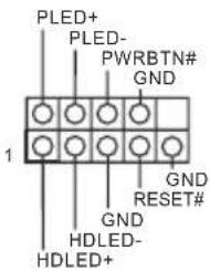
Snail OpenApagar o Jumper CMOS (CLRMOS1)
(ver p.1, N.° 30)

Apagar CMOSPadrão
text_image
GND +3VS B S_P W R DWN LA D 0 +3V LA D 3 P C I R 4 T FR A M E P C I C L K GND SER I R Q LA D 1 LA D 2 SM B _ D A T A _ M A I N SM B _ C L K _ M A I N Q NP 1Auto Lip Sync, Deep Color (12bpc), xvYCC 및 HBR (High Bit
CPU, GT_CPU, DRAM, VPPM, PCH 1.0V, VCCIO, VCCPLL,
VCCSA 전압 다중 조정
text_image
Snow OpenClear CMOS 점퍼 (CLRMOS1)
natural_image
Simple graphic with a magnifying glass icon and a horizontal line, no text or symbols present.1.1 パッケージの内容

1.2 仕様
CPU
'TM
Intel Z170
text_image
Snail Opentext_image
Snor Open清除 CMOS 跳線
(CLRMOS1)
(請參閱第1頁,編號
30)
清除 CMOS預設
Storage Technology 14, dan Intel Smart Response Technology), NCQ, AHCI, serta Hot Plug
CPU, DRAM, VPPM, PCH 1.0V, VCCIO, VCCSA
os
Enabling USB Ports for Windows ^® 7 Installation
Intel® Braswell and Skylake has removed their support for the Enhanced Host Controller Interface (EHCI – USB2.0) and only kept the eXtensible Host Controller Interface (XHCI – USB3.0). Due to that fact that XHCI is not included in the Windows 7 inbox drivers, users may find it difficult to install Windows 7 operating system because the USB ports on their motherboard won’t work. In order for the USB ports to function properly, please create a Windows® 7 installation disk with the Intel® USB 3.0 eXtensible Host Controller (xHCI) drivers packed into the ISO file.
Requirements
A Windows ^® 7 installation disk or USB drive
USB 3.0 drivers (included in the ASRock Support CD or website)
A Windows® PC
Win7 USB Patcher (included in the ASRock Support CD or website)
Scenarios
You have an ODD and PS/2 ports:
If there is an optical disc drive, PS/2 ports and PS/2 Keyboard or mouse on your computer, you can skip the instructions below and go ahead to install Windows ^® 7 OS.
You only have an ODD (For Intel Skylake platforms only):
If there is an optical disc drive but no PS/2 ports on your computer, please enable the "PS/2 Simulator" option in UEFI SETUP UTILITY > Advanced > USB Configuration, which allows the USB port to function as a PS/2 port, and then you can install the Windows® 7 OS. Please set PS/S Simulator back to disabled after the installation.
You've got nothing:
If you do not have an optical disc drive, please find another computer and follow the instructions below to create a new ISO file with the "Win7 USB Patcher". Then use the new patched Windows ^® 7 installation USB drive to install Windows ^® 7 OS.
Instructions
Step 1
Insert the Windows ^® 7 installation disk or USB drive to your system.
Step 2
Extract the tool (Win7 USB Patcher) and launch it.
Step 3
Select the "Win7 Folder" from Step1 by clicking the red circle as shown as the picture below.
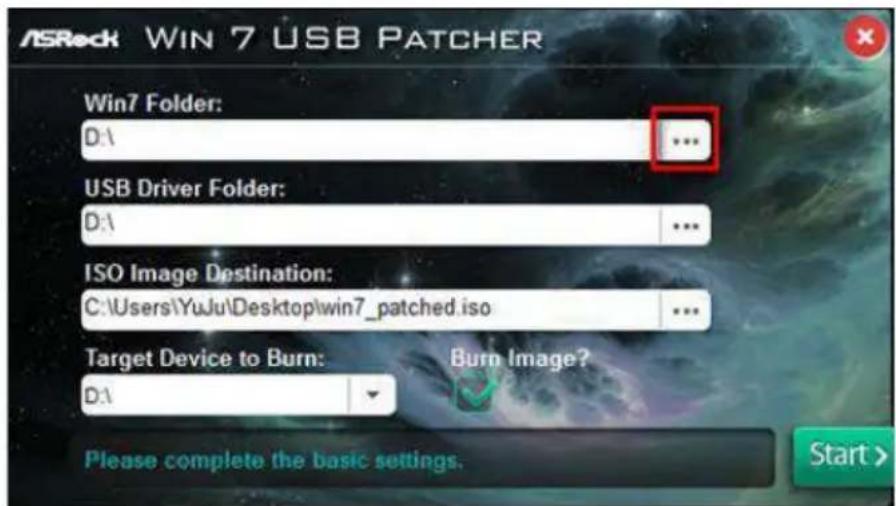
text_image
ASRock WIN 7 USB PATCHER Win7 Folder: D:1 ... USB Driver Folder: D:1 ... ISO Image Destination: C:\Users\YuJu\Desktop\win7_patched.iso ... Target Device to Burn: D:1 Burn Image? Please complete the basic settings. Start >Step 4
Select the "USB Driver Folder" by clicking the red circle as shown as the picture below.
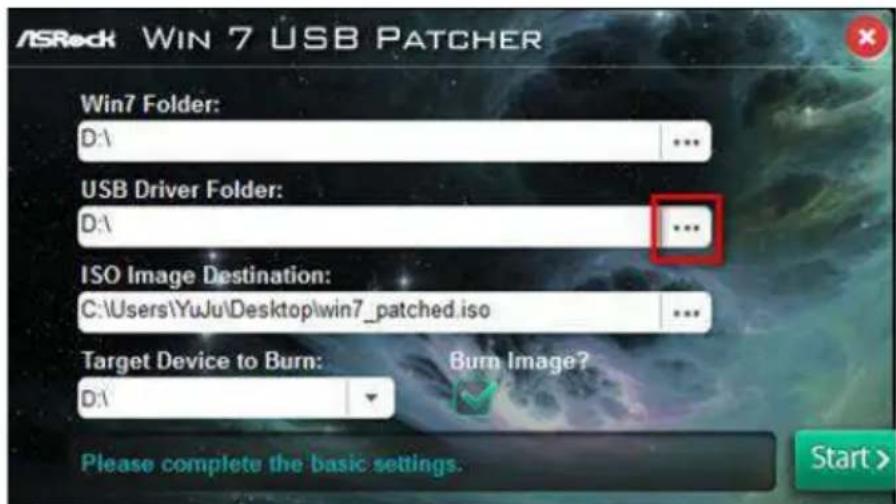
text_image
ASRock WIN 7 USB PATCHER Win7 Folder: D:\ ... USB Driver Folder: D:\ ... ISO Image Destination: C:\Users\YuJu\Desktop\win7_patched.iso ... Target Device to Burn: Burn Image? D:\ Please complete the basic settings. Start >If you are using ASRock's Support CD for the USB 3.0 driver, please select your CD-ROM.
Step 5
Select where to save the ISO file by pressing the red circle as shown as the picture below.
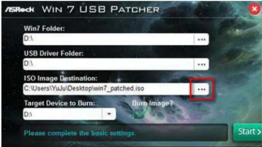
text_image
ASRock WIN 7 USB PATCHER Win7 Folder: D:\ ... USB Driver Folder: D:\ ... ISO Image Destination: C:\Users\YuJu\Desktop\win7_patched.iso ... Target Device to Burn: D:\ Burn Image? Please complete the basic settings. Start >Step 6
If you want to burn the patched image to a CD, please check “Burn Image” and select “Target Device to Burn”. If not, the patched ISO image will be exported to the destination selected in Step5. Then Press “Start” to proceed.
Step 7
Now you are able to install Windows ^® 7 on Braswell or Skylake with the new burned CD. Or please use the patched ISO image to make an OS USB drive to install the OS.
Contact Information
If you need to contact ASRock or want to know more about ASRock, you're welcome to visit ASRock's website at http://www.asrock.com; or you may contact your dealer for further information. For technical questions, please submit a support request form at http://www.asrock.com/support/tsd.asp
ASRock Incorporation
2F., No.37, Sec. 2, Jhongyang S. Rd., Beitou District,
Taipei City 112, Taiwan (R.O.C.)
ASRock EUROPE B.V.
Bijsterhuizen 3151
6604 LV Wijchen
The Netherlands
Phone: +31-24-345-44-33
Fax: +31-24-345-44-38
ASRock America, Inc.
13848 Magnolia Ave, Chino, CA91710
U.S.A.
Phone: +1-909-590-8308
Fax: +1-909-590-1026