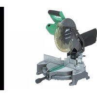
C10FCE2 - Saw HiKOKI - Free user manual and instructions
Find the device manual for free C10FCE2 HiKOKI in PDF.


| Product Type | Radial Miter Saw |
| Brand | HiKOKI |
| Model | C10FCE2 |
| Blade Dimensions | 255 mm diameter, bore 30 mm, thickness 2.3 mm |
| No-Load Speed | 5000 min-1 |
| Rated Power | 1520 W |
| Power Supply | 230 V (or 110 V depending on region) |
| Net Weight | 11.9 kg |
| Dimensions (L × D × H) | 460 mm × 628 mm × 561 mm |
| Cutting Capacity at 0° | 59 mm (height) × 144 mm (width) |
| Miter Cutting Capacity at 45° | 59 mm × 102 mm |
| Bevel Cutting Capacity at 45° (Left) | 41 mm × 144 mm |
| Miter Angle | 0° to 52° right and left |
| Bevel Angle | 0° to 45° left |
| Main Functions | Straight cut, miter, bevel, compound |
| Safety | Lower guard, head lock, protective cover |
| Maintenance | Monthly lubrication, regular cleaning, carbon brush inspection |
| Included Accessories | TCT blade 255 mm, chip tray, vice, wrenches, side handle |
| Repairability | Spare parts available, repair by authorized service |
| Sound Level | Sound pressure 95 dB(A), sound power 108 dB(A) |
| Vibration Value | 2.6 m/s² |
Frequently Asked Questions - C10FCE2 HiKOKI
User questions about C10FCE2 HiKOKI
0 question about this device. Answer the ones you know or ask your own.
Ask a new question about this device
Download the instructions for your Saw in PDF format for free! Find your manual C10FCE2 - HiKOKI and take your electronic device back in hand. On this page are published all the documents necessary for the use of your device. C10FCE2 by HiKOKI.
USER MANUAL C10FCE2 HiKOKI
Laser radiation is emitted from this aperture.
Laser radiation when open. Do not stare into beam.


LASER RADIATION-DO NOT STARE INTO BEAM
CLASS II LASER PRODUCT
Po<3mW.CS=3(lambda)=654nm.
Time basis 0.25 s
Standard: EC 60825-1:2001
EN60925-1:2001-11
AS/NZS 2211.1:1997
CAUTION-CLASS II LASER RADIATION
WHEN OPEN.
DO NOT STARE INTO THE BEAM

18

19

20

21

22

23

24

25
26 27


28 29


30
31

32
33
| English Deutsch Français | |||
| ①Handle Griff Poignée | |||
| ②Lock lever (C) Sperrhebel (C) Levier de verrouillage (C) | |||
| ③Motor Head Motorkopf Tête de moteur | |||
| ④Gear Case Getriebegehäuse Reducteur | |||
| ⑤Dust Bag Staubbeutel | Bacquet de réception des copeaux | ||
| ⑥Laser Marker (Only C10FCH2) Lasermarkierer (Nur C10FCH2) | Marqueur à laser(C10FCH2 seulement) | ||
| ⑦Turn Plate Drehplatte Plaque tournante | |||
| ⑧6mm Wing Bolt 6 mm-FlügelschraubBoulon à ailettes de 6 mm | |||
| ⑨Vise Assembly Schraubstocksatz Ensemble d'étau | |||
| ⑩Sub Fence (B) | Hilfsführung (B) | Guide auxiliaire (B) | |
| ⑪Fence (B)Gitter (B)Guide (B) | |||
| ⑫Turntable | Drehbihne | Plaque tournante | |
| ⑬Side HandleSeitengriff Poignée latérique | |||
| ⑭LeverHebelLevier | |||
| ⑮Indicator (A) (For miter scale) Zeiger (A) (Für Gehrungsskala) | Indicateur (A) (Pour l'échelle d'onglet) | ||
| ⑯Table InsertTischeinsatz Plaque d'insertion | |||
| ⑰Fence (A)Gitter (A)Guide (A) | |||
| ⑱Indicator (B)(For bevel scale) | Anzeiger (B)(Für Schrägschnittsskala) | Indicateur (B)(pour échelle de biseau) | |
| ⑲Lower Guard | Unterer Schutz | Guide inférieur | |
| ⑳Saw BladeSägeblettLame de scie | |||
| ①MotorMOTORMoteur | |||
| ②NameplateTypenschild Plaque signalétique | |||
| ③Trigger Switch Auslöserschalter | Interrupteur à détente | ||
| ④Switch (For laser marker)(Only C10FCH2) | Schalter (Für Lasermarkierer)(Nur C10FCH2) | Interrupteur (Pour marqueur à laser)(C10FCH2 seulement) | |
| ⑤BaseGrundplatteSocle | |||
| ⑥Holder (B) Halter (B) | Support (B) | ||
| ⑦Clamp Lever | Klemmhebel | Levier de serrage | |
| ⑧Locking Pin | Verriegelungsstift | Goupille de verrouillage | |
| ⑨DuctKanalConduit | |||
| ⑩Right Angle | Rechter Winkel | Angle droit | |
| ⑪LineLinieLigne | |||
| ⑫Warning Sign Warnsymbol | Signe d'advertissement | ||
| ⑬6 mm Bolt | 6 mm-Schraube | Boulon 6 mm | |
| ⑭M6 x 20 Screw | M6 x 20 Schraube | Vis M6 x 20 | |
| ⑮Screw Holder | Schraubenhalter | Support de vis | |
| ⑯6 mm Wing Bolt (B) | 6 mm-Flügelschraub (B) | Boulon à ailettes de 6 mm (B) | |
| ⑰Vise Shaft Schraubstockachse | Arbre de l'étau | ||
| ⑱6 mm Wing Bolt (A) | 6 mm-Flügelschraub (A) | Boulon à ailettes de 6 mm (A) | |
| ⑲WorkpieceWerkstückPiece | |||
| ⑳Vise Plate | Schraubstockbacke | Talon | |
| ⑴KnobKnopfBouton | |||
| ⑵M6 Flat screw | M6 Flache Schraube | Vis à tête plate M6 | |
| ⑶Plate (A)Platte (A)Plaque (A) | |||
| ⑷M6Nylon nutM6Nylon-Mutter Écrou en nylon M6 | |||
| ⑸M10BoltM10Schraube Boulon M10 | |||
| 46Laser line Laserlinie Raie laser | |||
| 47Groove Nut Rainure | |||
| 484mm Hex. Bar Wrench 4 mm-Sechs | kantschlussel Clé à tige hexagonale de 4 mm | ||
| 49Marking (pre-marked) Markierung (vord-gekennzeichnet) Marquage (pré-marqué) | |||
| 50Miter Scale Gehrungsskala Echelle d'onglet | |||
| 51Holder (Optional accessory) Halter (Sonderzubehör) Support (Accessoire en option) | |||
| 52Steel Square Stahlwinkel Equerre en acier | |||
| 536 mm Wing Nut (Optional accessory) | Flügelschraube, 6 mm(Sonderzubehör) | Ecrou à ailettes de 6 mm(Accessoire en option) | |
| 54Height Adjustment Bolt 6 mm(Optional accessory) | Höheneinstellschraube, 6 mm(Sonderzubehör) | Boulon de réglage de la hauteurde 6 mm (Accessoire en option) | |
| 55Base Surface | Grundfläche | Surface du socle | |
| 566 mm Wing Bolt(Optional accessory) | 6 mm-Flügelschraube Boulon à ailettes(Sonderzubehör) | 6 mm-Flügelschraube Boulon à ailettes de 6 mm(Accessoire en option) | |
| 57Stopper (Optional accessory) | Anschlag (Sonderzubehör) | Butée (Accessoire en option) | |
| 586 mm Wing Bolt(Optional accessory) | 6 mm-Flügelschraube Boulon à ailettes(Sonderzubehör) | 6 mm-Flügelschraube Boulon à ailettes de 6 mm(Accessoire en option) | |
| 596 mm Wing Bolt 6 mm-Flügelschraube Boulon à ailettes de 6 mm | |||
| 60Crown Molding Vise Ass'y(Optional accessory) | Schraubstocksatz fürKronenform (Sonderzubehör) | Ensemble d'étaut de corniche àcourbe complexe(Accessoire en option) | |
| 616 mm Wing Bolt 6 mm-Flügelschraube Boulon à ailettes de 6 mm | |||
| 626 mm Wing Bolt 6 mm-Flügelschraube Boulon à ailettes de 6 mm | |||
| 63Crown Molding Stopper (L)(Optional accessory) | Kronenformanschlag (L)(Sonderzubehör) | Butée de corniche à courbcoucle (L) (Accessoire en option) | |
| 64Crown Molding Stopper (R) Kron(Optional accessory) | enformanschlag (R)Butée(Sonderzubehör) | de corniche à courbcoucle (R) (Accessoire en option) | |
| 656 mm Knob Bolt | 6 mm-Knopfschraube | Vis moletée de 6 mm | |
| 66Knob KnopfBouton | |||
| 67Crown molding | Kronenform | Corniche à courbe complexe | |
| 684 mm Machine Screw | 4 mm-Maschinenschraube | Vis à métaux de 4 mm | |
| 69Spindle Cover | Spindelabdeckung | Couvercle de l'arbre | |
| 70Spindle Lock Spindelhebel Verrou en fuseau | |||
| 7110mm Box Wrench 10mm Steckschüssel Clé à écrous de 10 mm | |||
| 72Washer (B) | Unterlegscheibe (B) | Rondelle (B) | |
| 73Bolt Schraube Boulon | |||
| 74Washer Unterlegscheibe Rondelle | |||
| 75Washer (A) | Unterlegscheibe (A) | Rondelle (A) | |
| 76Color (A) Farbe (A) Couleur (A) | |||
| 77Hex. Head Bolt Sechskantschraube Boulon à tête hexagonale | |||
| 78Steel Square Stahlwinkel Equerre en acier | |||
| 79Wear limit line Verschleißgrenze | Repère de limite d'usure | ||
| 80Groove for Driver Aussparung für Schraubendreher | Rainure pour clé à écrous | ||
| 81Brush Cap Bürstenkappe Bouchon de carbone | |||
| Italiano Nederlands Espanol | |||
| 1Manico Greep Empuñadura | |||
| 2Leva di blocco (C) Vergrendelgreep (C) Palanca de fijación(C) | |||
| 3Testa motore Motorkop Cabezal del motor | |||
| 4Cassa ingranaggi Tandwielkast Caja de engranajes | |||
| 5Raccoglipolvere Stofzak Bolsa para elpolvo | |||
| 6Marcatore laser (Solo C10FCH2) | Lasemarkeerinrichting(Alleen voor C10FCH2) | Marcador láser (Sólo C10FCH2) | |
| 7Piatto girevole Draaischijf Placa giratioria | |||
| 8Vite ad alette da 6 mm 6 mm Vleugelbout Perno de aletas de 6 mm | |||
| 9Gruppo morsa | Bankschroef | Conjunto del tornillo de carpintero | |
| 10Guida secondaria (B) | Subgeleider (B) | Tope-guía secundario (B) | |
| 11Guida de appoggio (B) | Geleider (B) | Protección (B) | |
| 12Piatto girevole Draaitafel | Plataforma | ||
| 13Manico laterale | Zijgreep | Asa lateral | |
| 14Leva | Hendel | Palanca | |
| 15Indicatore (A)(Per la Scala di quartabuono) | Indicator (A)(Voor versteksaal) | Indicator (A)(Para escalade nivel) | |
| 16Inserimento davola | Tafel-inzetstuk | Inserto de mesa | |
| 17Guida de appoggio (A) | Geleider (A) | Protección (A) | |
| 18Indicatore (B)(Per Scala di smussatura) | Indicator (B)(Voor Afschuinschaal) | Indicator (B)(Para escalade en Bisel) | |
| 19Protezione inferiore | Onderste afscherming | Protector inferior | |
| 20Lama sega | Zaagblad | Cuchilla de sierra | |
| 21Motore | Motor Motor | ||
| 22Targhetta | Specificatieplaatje | Placa de identificación | |
| 23Interruttore a grilletto | Startschakelaar | Gatillo | |
| 24Interruttore (Per marcatore laser)(Solo C10FCH2) | Schakelaar(Voor lasemarkeerinrichting)(Alleen voor C10FCH2) | Interruptor (Para marcador láser)(Sólo C10FCH2) | |
| 25Base | Basis | Base | |
| 26Supporto (B) | Houder (B) | Soporte (B) | |
| 27Leva morsetto | Klemhendel | Palanca de fijación | |
| 28Perno di blocco | Vergrendelpen | Pasador de bloqueo | |
| 29Condotto Buis | Conducto | ||
| 30Angolo Retto | Rechte Hoek | Ángulo recto | |
| 31Riga | Lijnh | Linea | |
| 32Segnale di Aventamento | Waarschuwingssymbol | Señal de precaución | |
| 33Bullone da 6 mm | 6 mm bout | Perno de 6 mm | |
| 34Vite M6 × 20 | M6 × 20 Schroef | M6 × 20 tornillos | |
| 35Portavite | Schroefhouser | Sujetador de rosca | |
| 36Vite ad alette da 6 mm (B) | 6 mm Vleugelbout (B) | Perno de aletas de 6 mm (B) | |
| 37Albero della Morsa | Bankschroef Schacht | Eje de tornillo de carpintero | |
| 38Vite ad alette da 6 mm (A) | 6 mm Vleugelbout (A) | Perno de aletas de 6 mm (A) | |
| 39Pezzo da lavorare | Werkstuk | Pieza de trabajo | |
| 40Piastra morsa | Klemplaat | Placa de tornillo | |
| 41Manopola Knop | Perilla | ||
| 42Vite piatta M6 | M6 Platkopschroef | Tornillo plano M6 | |
| 43Piastra (A) | Schijf (A) | Placa (A) | |
| 44Dado di nylon M6 M6 Nylon moer | Tuerca de nylon M6 | ||
| Italiano Nederlands Espanol | |||
| 45Bullone M10 M10 Bout Perno M10 | |||
| 46Linea laser Laserstreep Linea de láser | |||
| 47Scanalatura Groef Ranura | |||
| 48Chiave a barra esionale da 4 mm 4 mm | 4 mm Imbus Steeksleutel | Llave de barra hexagonal de | |
| 49Marcatura (pre-contrassegnato) Markering (pre-pre-marked) Marcaje (pre-marcedo) | |||
| 50Scala di quartabuono Verstekschaal Escala de ingletes | |||
| 51Supporto (Accessoroli optionali) | Houder (Optionele toebehoren) | Sopporte (Accessorio optionals) | |
| 52Quadrato di acciaio Stalen winkelhaak Escuadra de acero | |||
| 53Dado ad alette da 6 mm (Accessorio opzionale) | 6 mm vleugelmoer (Optioneel toebehoren) | Tuerca de aletas de 6 mm (Accessorio optional) | |
| 54Bullone di regolazione altezza da 6 mm (Accessorio opzionale) | Hoogte.afstelbout 6 mm (Optioneel toebehoren) | Perno de ajuste de alta de 6 mm (Accessorio optional) | |
| 55Superficie della base | Voetplaat | Superficie de la base | |
| 56Vite ad alette da 6 mm (Accessorio opzionale) | 6mm Vleugelbout (Optioneel toebehoren) | Perno de aletas de 6 mm (Accessorio optional) | |
| 57Fermo (Accessoroli optionali) | Aanslag (Optionele toebehoren) | Retén (Accessorio optionals) | |
| 58Vite ad alette da 6 mm (Accessorio opzionale) | 6 mm Vleugelbout (Optionele toebehoren) | Perno de aletas de 6 mm (Accessorio optional) | |
| 59Vite ad alette da 6 mm | 6 mm Vleugelbout | Perno de aletas de 6 mm | |
| 60Gruppo morsa di modanatura a corona (Accessorio opzionale) | Kroonvormklem (Optioneel toebehoren) | Conj. de tornillo de carpintero para moldura en vortice (Accessorio optional) | |
| 61Vite ad alette da 6 mm | 6 mm Vleugelbout | Perno de aletas de 6 mm | |
| 62Vite ad alette da 6 mm | 6 mm Vleugelbout | Perno de aletas de 6 mm | |
| 63Fermo per modanatura a corona (L) (Accessorio opzionale) | Kroonvormstopper (L) (Optioneel toebehoren) | Retén de moldura en vortice (L) (Accessorio optional) | |
| 64Fermo per modanatura a corona (R) (Accessorio opzionale) | Kroonvormstopper (R) (Optioneel toebehoren) | Retén de moldura en vortice (R) (Accessorio optional) | |
| 65Bullone a manopola da 6 mm 6 mm bout Perno de perilla de 6 mm | |||
| 66Manopola Knop Perilla | |||
| 67Modanatura a corona | Kroonvorm | Moldura en vortice | |
| 68Vite da macchina da 4 mm | 4 mm Machine Schroef | Tornillo de máquina de 4 mm | |
| 69Coperchio dell'alberino | Drijfas-afdekking | Cubierta de husillo | |
| 70Fermo dell'alberino | Spilvergrendeling | Seguro del eje | |
| 71Chiave chisa de 10 mm | 10 mm naufbussleutel | Llave de tubo de 10 mm | |
| 72Rondella (B) Sluiting (B) Arandela (B) | |||
| 73Bullone Schroeif Perno | |||
| 74Rondella Sluiting Arandela | |||
| 75Rondella (A) Sluiting (A) Arandela (A) | |||
| 76Colore (A) Kleur (A) Color (A) | |||
| 77Bullone a Testa esagonale Imbus bout Perno de cabeza hexagonal | |||
| 78Quadrato di acciaio Stalen winkelhaak Escuadra de acero | |||
| 79Riga di limite usura | Slijtagegrens | Línea de limite de desgaste | |
| 80Scanalatura per elemento motore | Groef Schroevendraier | Ranura para herramienta | |
| 81Coperchio spazzola | Borstel Kap | Tapa de cepillo | |
WARNING! When using electric tools, basic safety precautions should always be followed to reduce the risk of fire, electric shock and personal injury, including the following.
Read all these instructions before operating this product and save these instructions.
For safe operations:
- Keep work area clean. Cluttered areas and benches invite injuries.
- Consider work area environment. Do not expose power tools to rain. Do not use power tools in damp or wet locations. Keep work area well lit. Do not use power tools where there is risk to cause fire or explosion.
- Guard against electric shock. Avoid body contact with earthed or grounded surfaces (e.g. pipes, radiators, ranges, refrigerators).
- Keep children and infirm persons away. Do not let visitors touch the tool or extension cord. All visitors should be kept away from work area.
- Store idle tools. When not in use, tools should be stored in a dry, high or locked up place, out of reach of children and infirm persons.
- Do not force the tool. It will do the job better and safer at the rate for which it was intended.
- Use the right tool. Do not force small tools or attachments to do the job of a heavy duty tool. Do not use tools for purposes not intended; for example, do not use circular saw to cut tree limbs or logs.
- Dress properly. Do not wear loose clothing or jewelry, they can be caught in moving parts. Rubber gloves and non-skid footwear are recommended when working outdoors. Wear protecting hair covering to contain long hair.
- Use eye protection. Also use face or dust mask if the cutting operation is dusty.
- Connect dust extraction equipment. Cutting operation by this compound miter saw may produce considerable amount of dust from extraction duct on fixed guard. (Dust material: Wood or Aluminium) If devices are provided for the connection of dust extraction and collection facilities ensure these are connected and properly used.
- Do not abuse the cord. Never carry the tool by the cord or yank it to disconnect it from the receptacle. Keep the cord away from heat, oil and sharp edges.
- Secure work. Use clamps or a vise to hold the work. It is safer than using your hand and it frees both hands to operate tool.
- Do not overreach. Keep proper footing and balance at all times.
- Maintain tools with care. Keep cutting tools sharp and clean for better and safer performance. Follow instructions for lubrication and changing accessories. Inspect tool cords periodically and if damaged, have it repaired by authorized service center. Inspect extension cords periodically and replace, if damaged. Keep handles dry, clean, and free from oil and grease.
- Disconnect tools. When not in use, before servicing, and when changing accessories such as blades, bits and cutters.
- Remove adjusting keys and wrenches. Form the habit of checking to see that keys and adjusting wrenches are removed from the tool before turning it on.
-
Avoid unintentional starting. Do not carry a plugged-in tool with a finger on the switch. Ensure switch is off when plugging in.
-
Use outdoor extension leads. When tool is used outdoors, use only extension cords intended for outdoor use.
- Stay alert. Watch what you are doing. Use common sense. Do not operate tool when you are tired.
- Check damaged parts. Before further use of the tool, a guard or other part that is damaged should be carefully checked to determine that it will operate properly and perform its intended function. Check for alignment of moving parts, free running of moving parts, breakage of parts, mounting and any other conditions that may affect its operation. A guard or other part that is damaged should be properly repaired or replaced by an authorized service center unless otherwise indicated in this handling instructions. Have defective switches replaced by an authorized service center. Do not use the tool if the switch does not turn it on and off.
- Warning
The use of any accessory or attachment, other than those recommended in this handling instructions, may present a risk of personal injury.
- Have your tool repaired by a qualified person.
This electric tool is in accordance with the relevant safety requirements. Repairs should only be carried out by qualified persons using original spare parts. Otherwise this may result in considerable danger to the user.
PRECAUTIONS ON USING COMPOUND MITER SAW
- Keep the floor area around the machine level. Well maintained and free of loose materials e.g. chips and cut-offs.
- Provide adequate general or localized lighting.
- Do not use power tools for applications other than those specified in the handling instructions.
- Repairing must be done only by authorized service facility. Manufacturer is not responsible for any damages and injuries due to the repair by the unauthorized persons as well as the mishandling of the tool.
- To ensure the designed operational integrity of power tools, do not remove installed covers or screws.
- Do not touch movable parts or accessories unless the power source has been disconnected.
- Use your tool at lower input than specified on the nameplate; otherwise, the finish may be spoiled and working efficiency reduced due to motor overload.
- Do not wipe plastic parts with solvent. Solvents such as gasoline, thinner, benzine, carbon tetrachloride, alcohol, may damage and crack plastic parts. Do not wipe them with such solvent. Clean plastic parts with a soft cloth lightly dampened with soapy water.
- Use only original HITACHI replacement parts.
- This tool should only be disassembled for replacement of carbon brushes.
- The exploded assembly drawing on this handling instructions should be used only for authorized service facility.
- Never cut ferrous metals or masonry.
- Adequate general or localized lighting is provided. Stock and finished workpieces are located close to the operators normal working position.
- Wear suitable personal protective equipment when necessary, this could include: Hearing protection to reduce the risk of induced hearing loss.
Eye protection to reduce the risk of injuring an eye. Respiratory protection to reduce the risk of inhalation of harmful dust.
Gloves for handling saw blades (saw blades shall be carried in a holder wherever practicable) and rough material.
- The operator is adequately trained in the use, adjustment and operation of the machine.
- Refrain from removing any cut-offs or other parts of the workpiece from the cutting area whilst the machine is running and the saw head is not in the rest position.
- Never use the compound miter saw with its lower guard locked in the open position.
- Ensure that the lower guard moves smoothly.
- Do not use the saw without guards in position, in good working order and properly maintained.
- Use correctly sharpened saw blades. Observe the maximum speed marked on the saw blade.
- Do not use saw blades which are damaged or deformed.
- Do not use saw blades manufactured from high speed steel.
- Use only saw blades recommended by HITACHI. Use of saw blade comply with EN847-1.
- The saw blades should be from 235mm to 255mm external diameter ranges.
- Select the correct saw blade for the material to be cut.
-
Never operate the compound miter saw with the saw blade turned upward or to the side.
-
Ensure that the workpiece is free of foreign matter such as nails.
- Replace the table insert when worn.
- Do not use the saw to cut other than aluminium, wood or similar materials.
- Do not use the saw to cut other materials than those recommended by the manufacturer.
- Blade replacement procedure, including the method for repositioning and a warning that this must be carried out correctly.
- Connect the compound miter saw to a dust collecting device when sawing wood.
- Take care when slotting.
- When transporting or carrying the tool, do not grasp the holder. Grasp the handle instead of the holder.
- Start cutting only after motor revolution reaches maximum speed.
- Promptly cut OFF the switch when abnormality observed.
- Shut off power and wait for saw blade to stop before servicing or adjusting tool.
- During a miter or bevel cut the blade should not be lifted until it has stopped rotation completely.
- Take all the possibility of residual risks in cutting operation into your consideration, such as the laser radiation to your eyes, the inadvertent access to moving parts on slide mechanical parts on machine and so on.
SPECIFICATIONS
| Max. Cutting Capacity Height × Width | 0° or | 59 mm × 144 mm 89 mm × 101 mm | |
| Miter 45° 59 mm × 102 mm | |||
| Bevel Left 45° 41 mm × 144 mm | |||
| Compound (Bevel Left 45°, Miter 45°) | 41 mm × 102 mm | ||
| Saw Blade Dimensions (oD × iD × Thickness) | 255 mm × 30 mm × 2.3 mm | ||
| Miter Cutting Angle Right and Left 0° – 52° | |||
| Bevel Cutting Angle Left 0° – 45° | |||
| Compound Cutting Angle Miter (Right and Left) 0° – 45° | |||
| Voltage (by areas)* (110 V, 230 V) | ✓ | ||
| Power Input* 1520 W | |||
| No-Load Speed 5000 min | -1 | ||
| Machine Dimensions (Width × Depth × Height) | 460 mm × 628 mm × 561 mm | ||
| Weight (Net) 12 kg (C10FCH2) / 11.9 kg (C10FCE2) | |||
| Laser Marker (Only Model C10FCH2) | Maximum output Po<3 mW Class Laser Product II | ||
| (Iambda) | 654 nm | ||
| Laser medium | Laser Diode | ||
- Be sure to check the nameplate on product as it is subject to change by areas.
STANDARD ACCESSORIES
(1) 255 mm TCT Saw blade (mounted on tool)
(2) Dust bag 1
(3) 10 mm Box wrench
(4)Vise Assembly 1
(5) 4 mm Hex.bar wrench (only C10FCH2)
(6) Sub Fence (B) 1
(7) Flat screw 1
(8) M6 Nylon nut 1
(9) Plate (A) 1
(10) Holder (B) 1
(11) Side handle 1
Standard accessories are subject to change without notice.
OPTIONAL ACCESSORIES (SOLD SEPARATELY)
(1) Extension Holder and Stopper
(2) Crown molding Vise Ass'y (Include Crown molding Stopper (L))
(3) Crown molding Stopper (L)
(4) Crown molding Stopper (R)
Optional accessories are subject to change without notice.
APPLICATION
Cutting various types of aluminium sash and wood.
UNPACKING
Carefully unpack the power tool and all related items (standard accessories).
Check carefully to make certain all related items (standard accessories) are present.
PRIOR TO OPERATION
1. Power source
Ensure that the power source to be utilized conforms to the power requirements specified on the product nameplate.
2. Power switch
Ensure that the power switch is in the OFF position. If the plug is connected to a receptacle while the trigger switch is in the ON position, the power tool will start operating immediately, inviting serious accident.
3. Extension cord
When the work area is removed from the power source, use an extension cord of sufficient thickness and rated capacity. The extension cord should be kept as short as practicable.
4. When the power tool is prepared for shipping, its main parts are secured by a locking pin
Move the handle slightly so that the locking pin can be disengaged.
CAUTION
Set for transport
Lock the locking pin into the gear case (Fig. 3).
Remove a 6mm wing bolt. Turn the turn plate as the Fig. 5, and fix it again with the 6mm wing bolt.
Lower guard cover the teeth of the blade to the front of the machine.
Cutting work
Move the handle slightly so that the locking pin can be disengaged.
Remove a 6mm wing bolt. Turn the turn plate as Fig. 6, and fix it again with the 6mm wing bolt.
5. Attach the dust bag to the main unit (Fig. 1)
(1) When the dust bag has become full of sawdust, dust will be blown out of the dust bag when the saw blade rotates.
Check the dust bag periodically and empty it before it becomes full.
(2) During bevel and compound cutting, attach the dust bag at a right angle to the base surface as shown in Fig. 4.
CAUTION
Empty the dust bag frequently to prevent the duct and the safety cover from becoming clogged.
Sawdust will accumulate more quickly than normal during bevel cutting.
6. Installation
Ensure that the machine is always fixed to bench.
Attach the power tool to a level, horizontal work bench. Select 8mm diameter bolts suitable in length for the thickness of the work bench.
Bolt length should be at least 35mm plus the thickness of the work bench.
For example, use 8mm× 60mm bolts for a 25mm thick work bench.
ADJUSTING THE POWER TOOL PRIOR TO USE
CAUTION
Make all necessary adjustments before inserting the plug in the power source.
1. Check to see that the lower guard operates smoothly CAUTION
This compound miter saw is equipped with a saw head lock as safety device.
Tolower the saw head to cut, the lock must be released by pressing the lock lever (C) with your thumb.
(1) When you push down the handle while pushing the lock lever (C), check that the lower guard revolves smoothly (Fig. 7).
(2) Next, check that the lower guard returns to the original position when the handle is raised.
PRACTICAL APPLICATIONS
WARNING
To avoid personal injury, never remove or place a workpiece on the table while the tool is being operated.
Never place your limbs inside of the line next to warning sign while the tool is being operated. This may cause hazardous conditions (see Fig. 8).
CAUTION
It is dangerous to remove or install the workpiece while the saw blade is turning.
When sawing, clean off the shavings from the turntable.
Of the shavings accumulate too much, the saw blade from the cutting material will be exposed. Never subject your hand or anything else to go near the exposed blade.
1. Tightly secure the material by vise assembly to be cut so that it does not move during cutting
2. Switch operation
Pulling the trigger turns the switch on. Releasing the trigger turns the switch off.
3. Holder (B), clamp lever adjustment (Fig. 9)
Attach the included holder (B) in the position as shown in Fig. 9 and adjust the holder (B) until its bottom surface contacts the work bench surface. After adjustments, securely tighten the 6mm bolt with the included 10mm box wrench. Loosen the M6× 20 screw on the clamp lever and attach to a position where the clamp lever can be easily operated.
4. Using the Vise Assembly (Standard accessory) (Fig. 10)
(1) The vise assembly can be mounted on either the left fence Fence(B) or the right fence Fence(A) by loosening the 6mm wing bolt (A).
(2) The screw holder can be raised or lowered according to the height of the workpiece by loosening the 6mm wing bolt (B). After the adjustment, firmly tighten the 6mm wing bolt (B) and fix the screw holder.
(3) Turn the upper knob and securely fix the workpiece in position.
WARNING
Always firmly clamp or vise to secure the workpiece to the fence; otherwise the workpiece might be thrust from the table and cause bodily harm.
CAUTION
Always confirm that the motor head does not contact the vise assembly when it is lowered for cutting. If there is any danger that it may do so, loosen the 6 mm wing bolt and move the vise assembly to a position where it will not contact the saw blade.
5. Install the sub fence (B) (Fig. 11)
In the case of direct angle cutting and angle cutting, use the sub fence. The sub fence (B) can be installed on the right side of the guide fence (B). Place the attached plate (A) in the position as shown in Fig. 11, insert the tip in the groove of fence (B) and simultaneously, insert flathead screw M6 into fence (B), sub fence (B), and plate (A), then tighten nylon nut M6 with the included 10mm box wrench until the sub fence (B) can smoothly rotate. Then, you can realize stable cutting of the material with a wide back face.
WARNING
In the case of left bevel cutting, rotate the sub fence (B). Supposing it is not able to rotate it, it will contact the blade or some part of the tool, causing in serious injury to operator.
6. Using an ink line
Upon lowering the motor section, the lower guard is raised and the saw blade appears. Align the ink line with the saw blade.
CAUTION
Never lift the lower guard while the saw blade is rotating.
The sub fence will not only make contact and adversely affect cutting accuracy, this could also result in damage to the guard.
7. Install the side handle (Fig. 12)
Remove the M10 bolt and install the side handle that came enclosed with this unit.
8. Position adjustment of laser line (Only Model C10FCH2)
Ink lining can be easily made on this tool to the laser marker. A switch lights up the laser marker (Fig. 13). Depending upon your cutting choice, the laser line can be aligned with the left side of the cutting width (saw blade) or the ink line on the right side.
The laser line is adjusted to the width of the saw blade at the time of factory shipment. Adjust the positions of the saw blade and the laser line taking the following steps to suit the use of your choice.
(1) Light up the laser marker and make a groove of about 5 mm deep on the workpiece that is about 38mm in height and 89mm in width. Hold the grooved workpiece by vise as it is and do not move it.
(2) Then insert a 4mm hex. bar wrench in the 12 diameter hole on the side of the gear case, turn the hex. socket set screw to move the laser line. (If you turn the Hex. socket screw clockwise, the laser line will shift to the right and if you turn it counterclockwise, the laser line will shift to the left.) When you work with the ink line aligned with the left side of the saw blade, align the laser line with the left end of the groove (Fig. 14). When you align it with the right side of the saw blade, align the laser line with the right side of the groove.
(3) After adjusting the position of the laser line, draw a right-angle ink line on the workpiece and align the ink line with the laser line. When aligning the ink line, slide the workpiece little by little and secure it by vise at a position where the laser line overlaps with the ink line. Work on the grooving again and check the position of the laser line. If you wish to change the laser line's position, make adjustments again following the steps from (1) to (3).
WARNING (Fig. 16 and Fig. 17)
Make sure before plugging the power plug into the receptacle that the main body and the laser marker are turned off.
Exercise utmost caution in handling a switch trigger for the position adjustment of the laser line, as the power plug is plugged into the receptacle during operation. If the switch trigger is pulled inadvertently, the saw blade can rotate and result in unexpected accidents.
Do not remove the laser marker to be used for other purposes.
CAUTION
Laser radiation - Do not stare into beam.
Laser radiation on work table. Do not stare into beam. If your eye is exposed directly to the laser beam, it can be hurt.
Do not dismantle it.
Do not give strong impact to the laser marker (main body of tool); otherwise, the position of a laser line can go out of order, resulting in the damage of the laser marker as well as a shortened service life.
Keep the laser marker lit only during a cutting operation. Prolonged lighting of the laser marker can result in a shortened service life.
Use of controls or adjustments or performance of procedures other than those specified herein may result in hazardous radiation exposure.
NOTE
Perform cutting by overlapping the ink line with the laser line.
When the ink line and the laser line are overlapped, the strength and weakness of light will change, resulting in a stable cutting operation because you can easily discern the conformity of lines. This ensures the minimum cutting errors.
In outdoor or near-the-window operations, it may become difficult to observe the laser line due to the sunlight. Under such circumstances, move to a place that is not directly under the sunlight and engage in the operation.
Do not tug on the cord behind the motor head or hook your finger, wood and the like around it; otherwise, the cord may come off and the laser marker may not be lit up.
Check and make sure on a periodic basis if the position of the laser line is in order. As regards the checking method, draw a right-angle ink line on the workpiece with the height of about 38mm and the width of 89 mm, and check that the laser line is in line with the ink line [The deviation between the ink line and the laser line should be less than the ink line width (0.5 mm)] (Fig. 15).
9. Cutting operation
(1) As shown in Fig. 18 the width of the saw blade is the width of the cut. Therefore, slide the workpiece to the right (viewed from the operator's position) when length 已 is desired, or to the left when length 已 is desired.
(Only Model C10FCH2)
If a laser marker is used, align the laser line with the left side of the saw blade, and then align the ink line with the laser line.
(2) Once the saw blade reaches maximum speed, slowly push down the handle while pushing the lock lever (C) and bring the saw blade in the vicinity of the material to be cut.
(3) Once the saw blade contacts the workpiece, push the handle down gradually to cut into the workpiece.
(4) After cutting the workpiece to the desired depth, turn the power tool OFF and let the saw blade stop completely before raising the handle from the workpiece to return it to the full retract position.
CAUTION
For maximum dimensions for cutting, refer to "SPECIFICATIONS" table.
Increased pressure on the handle will not increase the cutting speed. On the contrary, too much pressure may result in overload of the motor and/or decreased cutting efficiency.
Confirm that the trigger switch is turned OFF and the power plug has been removed from the receptacle whenever the tool is not in use.
Always turn the power off and let the saw blade stop completely before raising the handle from the workpiece. If the handle is raised while the saw blade is still rotating, the cut-off piece may become jammed against the saw blade causing fragments to scatter about dangerously.
Every time one cutting of deep-cutting operation is finished, turn the switch off, and check that the saw blade has stopped. Then raise the handle, and return it to the full retract position.
Be absolutely sure to remove the cut material from the top of the turntable, and then proceed to the next step.
10. Miter cutting procedures
(1) Loosen the side handle and push the lever for angle stoppers. Then, adjust the turntable until the indicator aligns with desired setting on the miter scale (Fig. 19).
(2) Re-tighten the side handle to secure the turntable in the desired position.
NOTE
Positive stops are provided at the right and left of the 0^ center setting, at 15^ , 22.5^ , 31.6^ and 45^ settings. Check that the miter scale and the tip of the indicator are properly aligned.
Operation of the saw with the miter scale and indicator out of alignment, or with the side handle not properly tightened, will result in poor cutting precision.
CAUTION
- Never remove the side handle; use of the tool without it would be hazardous.
Toprevent an accident or personal injury always firmly tighten the miter handle.
11. Bevel cutting procedures (Fig. 20 and Fig. 21)
(1) Loosen the clamp lever and bevel the saw blade to the left.
(2) Adjust the bevel angle to the desired setting while watching the bevel angle scale and indicator, then secure the clamp lever.
WARNING
When the workpiece is secured on the left or right side of the blade, the short cut-off portion will come
to rest on the right or left side of the saw blade. Always turn the power off and let the saw blade stop completely before raising the handle from the workpiece.
If the handle is raised while the saw blade is still rotating, the cut-off piece may become jammed against the saw blade causing fragments to scatter about dangerously.
When stopping the bevel cutting operation halfway, start cutting after pulling back the motor head to the initial position.
Starting from halfway, without pulling back, causes the safety cover to be caught in the cutting groove of the workpiece and to contact the saw blade.
12. Compound cutting procedures
Compound cutting can be performed by following the instructions in 9 and 10 above. For maximum dimensions for compound cutting, refer to "SPECIFICATIONS" table.
CAUTION
Always secure the workpiece with the right hand side for compound cutting. Never rotate the table to the right for compound cutting, because the saw blade might then contact the clamp or vise that secures the workpiece, and cause personal injury or damage.
13. Cutting long materials
When cutting long materials, use an auxiliary platform which is the same height as the holder (optional accessory) and base of the special auxiliary equipment.
Capacity: wooden material (W× H× L)
120mm× 40mm× 1000mm
14. Installing the holders (Optional accessory)
The holders help keep longer workpieces stable and in place during the cutting operation.
(1) As indicated in Fig. 22, use a steel square for aligning the upper edge of the holders with the base surface. Loosen the 6mm wing nut. Turn a height adjustment bolt 6mm , and adjust the height of the holder.
(2) After adjustment, firmly tighten the wing nut and fasten the holder with the 6mm knob bolt (optional accessory). If the length of Height Adjustment Bolt 6 mm is insufficient, spread a thin plate beneath. Make sure the end of Height Adjustment Bolt 6mm does not protrude from the holder.
15. Stopper for precision cutting (Stopper and holder are optional accessory)
The stopper facilitates continuous precision cutting in lengths of 280mm to 450mm .
Toinstall the stopper, attach it to the holder with the 6 mm wing bolt as shown in Fig. 23.
16. Confirmation for use Crown molding vise, Crown molding Stopper (L) and (R) (Optional accessory)
(1) Crown molding Stopper (L) and (R) (optional accessories) allow easier cuts of crown molding without tilting the saw blade. Install them in the base both-sides side to be shown in Fig. 24. After inserting tighten the 6mm knob bolts to secure the Crown molding Stoppers.
(2) The crown molding vise (B) (Optional accessory) can be mounted on either the left fence (Fence (B)) or the right fence (Fence (A)). It can unite with the slope of the crown molding and vice can be pressed down.
Then turn the upper knob, as necessary, to securely attach the crown molding in position. To raise or lower
the vise assembly, first loosen the 6mm wing bolt. After adjusting the height, firmly tighten the 6mm wing bolt; then turn the upper knob, as necessary, to securely attach the crown molding in position (See Fig 25).
Position crown molding with its WALL CONTACT EDGE against the guide fence and its CEILING CONTACT EDGE against the Crown molding Stoppers as shown in Fig. 25. Adjust the Crown molding Stoppers according to the size of the crown molding. Tighten the 6mm wing bolt to secure the Crown molding Stoppers.
WARNING
Always firmly clamp or vise to secure the crown molding to the fence; otherwise the crown molding might be thrust from the table and cause bodily harm. Do not bevel cutting. The main body or saw blade may contact the sub fence, resulting in an injury.
CAUTION
Always confirm that the motor head (see Fig. 1) does not contact the crown molding vise assembly when it is lowered for cutting. If there is any danger that it may do so, loosen the 6mm knob bolt and move the crown molding vise assembly to a position where it will not contact the saw blade.
MOUNTING AND DISCOUNTING SAW BLADE
WARNING
Toprevent an accident or personal injury, always turn off the trigger switch and disconnect the power plug from the receptacle before removing or installing a blade.
If cutting work is done in a state where the bolt is not sufficiently tightened, the bolt can get loose, the blade can come off, and the lower guard can get damaged, resulting in injuries.
Also, check that the bolts are properly tightened before plugging the power plug into the receptacle.
Of the bolts are attached or detached using tools other than the 10mm box wrench (standard accessory), excessive or improperly tightening occurs, resulting in injury.
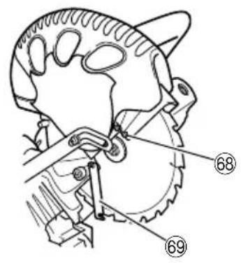
- Mounting the saw blade (Fig. 26, Fig. 27, Fig. 28 and Fig. 29)
(1) Rotate the lower guard (plastic) to the top position.
(2) Use the driver to loosen the 4mm screw fastening the spindle cover and then remove the spindle cover.
(3) Press in spindle lock and loosen bolt with 10mm box wrench (standard accessory).
Since the bolt is left-hand threaded, loosen by turning it to the right as show in Fig. 28.
NOTE
If the spindle lock cannot be easily pressed in to lock the spindle, turn the bolt with 10~mm box wrench (standard accessory) while applying pressure on the spindle lock. The saw blade spindle is locked when the spindle lock is pressed inward.
(4) Remove the bolt and washer (B).
(5) Lift the lower guard and mount the saw blade.
WARNING
When mounting the saw blade, confirm that the rotation indicator mark on the saw blade and the rotation direction of the gear case (see Fig. 1) are properly matched.
(6) Thoroughly clean washer (B) and the bolt, and install them onto the saw blade spindle.
(7) Press in the spindle lock and tighten the bolt by turning it to the left by standard accessories wrench(10 mm box wrench) as indicated in Fig. 28.
CAUTION
Confirm that the spindle lock has returned to the retract position after installing or removing the saw blade.
- Tighten the bolt so it does not come loose during operation.
Confirm that the bolt has been properly tightened before the power tool is started.
2. Dismounting the saw blade
Dismount the saw blade by reversing the mounting procedures described in paragraph 1 above.
The saw blade can easily be removed after lifting the lower guard.
CAUTION
Never attempt to install saw blades except 235~mm - 255~mm in diameter.
MAINTENANCE AND INSPECTION
WARNING
To avoid an accident or personal injury, always confirm the trigger switch is turned OFF and that the power plug has been disconnected from the receptacle before performing any maintenance or inspection of this tool.
1. Inspecting the saw blade
Always replace the saw blade immediately upon the first sign of deterioration or damage.
A damaged saw blade can cause personal injury and a worn saw blade can cause ineffective operation and possible overload to the motor.
CAUTION
Never use a dull saw blade. When a saw blade is dull, its resistance to the hand pressure applied by the tool handle tends to increase, making it unsafe to operate the power tool.
2. Inspecting the lever (Fig. 30 and Fig. 31)
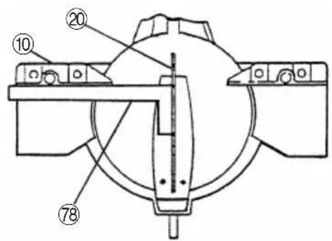
If the M6 hexagonal head bolts (2) are loose, align the sides of the fence and saw blade with the steel square. After adjusting the saw blade and fence to a ninety-degree angle, tighten the lever securing hexagonal head bolts (2).
3. Inspecting the carbon brushes (Fig. 32 and Fig. 33)
The carbon brushes in the motor are expendable parts.
If the carbon brushes become excessively worn, motor trouble might occur.
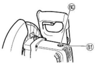
Therefore, inspect the carbon brushes periodically and replace them when they have become worn to the wear limit line as shown in Fig. 32.
Also, keep the carbon brushes clean so that they will slide smoothly within the brush holders.
The carbon brushes can easily be removed after removal of the brush caps (see Fig. 33) with a slotted (minus) screwdriver.
4. About Handling the Motor (see Fig. 1)
Winding of the motor is said to be the heart of this tool. Exercise utmost caution not to damage the winding by exposing it to wash oil or water.
NOTE
Accumulation of dust and the like inside the motor can result in a malfunction.
After using the motor for 50 hours or so, carry out no-load running, and blow in the dry air from a wind hole at the motor's rear. Such action is effective to discharge dust and the like.
5. Inspecting the screws
Regularly inspect each component of the power tool for looseness.
Re-tighten screws on any loose part.
WARNING
To prevent personal injury, never operate the power tool if any components are loose.
6. Inspecting the lower guard for proper operation
Before each use of the tool, test the lower guard (see Fig. 7) to assure that it is in good condition and that it moves smoothly.
Never use the tool unless the lower guard operates properly and it is in good mechanical condition.
7. Storage
After operation of the tool has been completed, check that the following has been performed:
(1) Trigger switch is in OFF position,
(2) Power plug has been removed from the receptacle,
(3) When the tool is not in use, keep it stored in a dry place out of the reach of children.
8. Lubrication
Lubricate the following sliding surfaces once a month to keep the power tool in good operating condition for a long time (Fig. 1 and Fig. 2).
Use of machine oil is recommended.
Oil supply points:
- Rotary portion of hinge
- Rotary portion of vise assembly
9. Cleaning
Periodically remove chips, dust and other waste material from the surface of the power tool, especially from the inside of the lower guard with a damp, soapy cloth. To avoid a malfunction of the motor, protect it from contact with oil or water.
(Only Model C10FCH2)
If the laser line becomes invisible due to chips and the like adhered onto the window of the laser marker's light-emitting section, wipe and clean the window with a dry cloth or a soft cloth moistened with soapy water, etc.
10. Service parts list
A:Item No.
B:Code No.
C:No. Used
D:Remarks
CAUTION
Repair, modification and inspection of Hitachi Power Tools must be carried out by a Hitachi Authorized Service Center.
Especially laser device should be maintained by the authorized agent by laser manufacturer.
Always assign the repair of laser device to Hitachi Authorized Service Center.
This Parts List will be helpful if presented with the tool to the Hitachi Authorized Service Center when requesting repair or other maintenance.
In the operation and maintenance of power tools, the safety regulations and standards prescribed in each country must be observed.
MODIFICATIONS
Hitachi Power Tools are constantly being improved and modified to incorporate the latest technological advancements.
Accordingly, some parts (i.e. code numbers and/or design) may be changed without prior notice.
GUARANTEE
We guarantee Hitachi Power Tools in accordance with statutory/country specific regulation. This guarantee does not cover defects or damage due to misuse, abuse, or normal wear and tear. In case of complaint, please send the Power Tool, undismantled, with the GUARANTEE CERTIFICATE found at the end of this Handling instruction, to a Hitachi Authorized Service Center.
NOTE
Due to HITACHI's continuing program of research and development the specifications herein are subject to change without prior notice.
IMPORTANT
Correct connection of the plug
The wires of the main lead are coloured in accordance with the following code:
Blue: -Neutral
Brown:Live
As the colours of the wires in the main lead of this tool may not correspond with the coloured markings identifying the terminals in your plug proceed as follows: The wire coloured blue must be connected to the terminal marked with the letter N or coloured black. The wire coloured brown must be connected to the terminal marked with the letter L or coloured red. Neither code must be connected to the earth terminal.
NOTE
This requirement is provided according to BRITISH STANDARD 2769:1984.
Therefore, the letter code and colour code may not be applicable to other markets except The United Kingdom.
Information concerning airborne noise and vibration
The measured values were determined according to EN61029.
The typical A-weighted sound pressure level: 95 dB (A) The typical A-weighted sound power level: 108 dB (A) Wear ear protection.
The typical weighted root mean square acceleration value: 2.6m / s^2
Information for power supply system to be used with electric tools provided with rated voltage 230V
Switching operations of electric apparatus cause voltage fluctuations.
The operation of this electric tool under unfavorable mains conditions can have adverse effects to the operation of other electric apparatus.
With a mains impedance equal or less than 0.29 Ohms there will probably be no negative effects.
Usually, the maximum permissible mains impedance will not be exceeded when the branch to the power outlet is fed from a junction box with a service capacity of 25 ampere or higher.
In case of power failure, or when the power plug is pulled out, immediately return the switch to OFF position. This prevents an uncontrolled restart.
APPLICATIONS PRATIQUES
AVERTISSEMENT
Siemensring 34, 47877 willich 1, F. R. Germany
Tel: +49 2154 49930
Fax: +49 2154 499350
URL: http://www.hitachi-powertools.de
Hitachi Power Tools Netherlands B. V.
Brabanthaven 11, 3433 PJ Nieuwegein, The Netherlands
Tel: +31 30 6084040
Fax: +31 30 6067266
URL: http://www.hitachi-powertools.nl
Hitachi Power Tools (U. K.) Ltd.
Precedent Drive, Rooksley, Milton Keynes, MK 13, 8PJ, United Kingdom
Tel: +44 1908 660663
Fax: +44 1908 606642
URL: http://www.hitachi-powertools.co.uk
Hitachi Power Tools France S. A. S.
Prac del'Eglantier 22, rue des Crerisiers Lisses, C. E. 1541,
91015 EVRY CEDEX, France
Tel: +33 169474949
Fax: +33 1 60861416
URL: http://www.hitachi-powertools.fr
Hitachi Power Tools Belgium N.V. / S.A.
Koningin Astridlaan 51, 1780 Wemmel, Belgium
Tel: +32 2 460 1720
Fax: +32 2 460 2542
URL http://www.hitachi-powertools.be
Hitachi Fercad Power Tools Italia S.p.A
Via Retrone 49-36077, Altavilla Vicentina (VI), Italy
Tel: +39 0444 548111
Fax: +39 0444 548110
URL: http://www.hitachi-powertools.it
Hitachi Power Tools Iberica, S.A.
C / Migjorn, s/n, Poligono Norte, 08226 Terrassa, Barcelona, Spain
Tel: +34 93 735 6722
Fax: +34 93 735 7442
URL: http://www.hitachi-powertools.es
- PRECAUTIONS ON USING COMPOUND MITER SAW
- STANDARD ACCESSORIES
- OPTIONAL ACCESSORIES (SOLD SEPARATELY)
- APPLICATION
- UNPACKING
- PRIOR TO OPERATION
- Power source
- Power switch
- Extension cord
- When the power tool is prepared for shipping, its main parts are secured by a locking pin
- CAUTION
- Attach the dust bag to the main unit (Fig. 1)
- Installation
- ADJUSTING THE POWER TOOL PRIOR TO USE
- Check to see that the lower guard operates smoothly CAUTION
- PRACTICAL APPLICATIONS
- WARNING
- Tightly secure the material by vise assembly to be cut so that it does not move during cutting
- Switch operation
- Holder (B), clamp lever adjustment (Fig. 9)
- Using the Vise Assembly (Standard accessory) (Fig. 10)
- Install the sub fence (B) (Fig. 11)
- Using an ink line
- Install the side handle (Fig. 12)
- Position adjustment of laser line (Only Model C10FCH2)
- WARNING (Fig. 16 and Fig. 17)
- NOTE
- Cutting operation
- Miter cutting procedures
- Bevel cutting procedures (Fig. 20 and Fig. 21)
- Compound cutting procedures
- Cutting long materials
- Installing the holders (Optional accessory)
- Stopper for precision cutting (Stopper and holder are optional accessory)
- Confirmation for use Crown molding vise, Crown molding Stopper (L) and (R) (Optional accessory)
- MOUNTING AND DISCOUNTING SAW BLADE
- Dismounting the saw blade
- MAINTENANCE AND INSPECTION
- Inspecting the saw blade
- Inspecting the lever (Fig. 30 and Fig. 31)
- Inspecting the carbon brushes (Fig. 32 and Fig. 33)
- About Handling the Motor (see Fig. 1)
- Inspecting the screws
- Inspecting the lower guard for proper operation
- Storage
- Lubrication
- Cleaning
- (Only Model C10FCH2)
- Service parts list
- MODIFICATIONS
- GUARANTEE
- IMPORTANT
- Information concerning airborne noise and vibration
- APPLICATIONS PRATIQUES
- AVERTISSEMENT
- Hitachi Power Tools Netherlands B. V.
- Hitachi Power Tools (U. K.) Ltd.
- Hitachi Power Tools France S. A. S.
- Hitachi Power Tools Belgium N.V. / S.A.
- Hitachi Fercad Power Tools Italia S.p.A
- Hitachi Power Tools Iberica, S.A.
Brand : HiKOKI
Model : C10FCE2
Category : Saw