
DH45MEY - Hammer HiKOKI - Free user manual and instructions
Find the device manual for free DH45MEY HiKOKI in PDF.
| Product type | Rotary hammer |
| Brand | HiKOKI |
| Model | DH45MEY |
| Rated voltage | 220-240 V~ |
| Power consumption | 1500 W |
| No-load speed | 120-310 min⁻¹ |
| Full load impact rate | 1200-2950 min⁻¹ |
| Max drilling capacity (concrete) | 45 mm |
| Max core bit capacity | 125 mm |
| Weight (according to EPTA 01/2003) | 9.5 kg |
| Chuck type | SDS-max |
| Functions | Rotation + percussion, percussion only, rotation only (via adjustment) |
| Integrated protections | Anti-vibration protection, overload protection, thermal protection, circuit protection, control monitoring |
| Sound pressure level (LpA) | 96 dB(A) |
| Sound power level (LWA) | 107 dB(A) |
| Vibration (drilling in concrete) | 8.8 m/s² (uncertainty K = 1.5 m/s²) |
| Vibration (equivalent chiseling) | 9.2 m/s² (uncertainty K = 1.5 m/s²) |
| Included accessories | Side handle, depth gauge, plastic case, hammer grease |
| Maintenance and cleaning | Replace grease every 6 months, check fixing screws, inspect drill bits (sharpen if necessary) |
| Spare parts and repairability | Use genuine HiKOKI parts, entrust repairs to an authorized service center |
| Safety | Wear ear protectors, dust mask, use a socket with RCD (≤30 mA) |
Frequently Asked Questions - DH45MEY HiKOKI
User questions about DH45MEY HiKOKI
0 question about this device. Answer the ones you know or ask your own.
Ask a new question about this device
Download the instructions for your Hammer in PDF format for free! Find your manual DH45MEY - HiKOKI and take your electronic device back in hand. On this page are published all the documents necessary for the use of your device. DH45MEY by HiKOKI.
USER MANUAL DH45MEY HiKOKI
natural_image
Line drawing of a DH45MEY drill press tool with helical end and central shaft (no text or symbols on the diagram itself)
en Handling instructions
de Bedienungsanleitung
fr Mode d'emploi
it Istruzioni per l'uso
nl Gebruiksaanwijzing
es Instrucciones de manejo
pt Instruções de uso
sv Bruksanvisning
da Brugsanvisning
no Bruksanvisning
fi Käyttöohjeet
el Οδηγίες χειρισμού
pl Instrukcja obsługi
hu Kezelési utasítás
cs Návod k obsluze
tr Kullanım talimatları
ro Instructiuni de utilizare
sl Navodila za rokovanje
sk Pokyny na manipuláciu
bg Инструкция за експлоатация
sr Uputstvo za rukovanje
hr Upute za rukovanje
UK Інструкції щодо поводження з пристроєм
ru Инструкция по эксплуатации
(Original instructions)
GENERAL POWER TOOL SAFETY WARNINGS

WARNING
Read all safety warnings and all instructions.
Failure to follow the warnings and instructions may result in electric shock, fi re and/or serious injury.
Save all warnings and instructions for future reference.
The term “power tool” in the warnings refers to your mains-operated (corded) power tool or battery-operated (cordless) power tool.
1) Work area safety
a) Keep work area clean and well lit. Cluttered or dark areas invite accidents
b) Do not operate power tools in explosive atmospheres, such as in the presence of fl ammable liquids, gases or dust.
Power tools create sparks which may ignite the dust or fumes.
c) Keep children and bystanders away while operating a power tool.
Distractions can cause you to lose control.
2) Electrical safety
a) Power tool plugs must match the outlet. Never modify the plug in any way.
Do not use any adapter plugs with earthed (grounded) power tools.
Unmodified plugs and matching outlets will reduce risk of electric shock.
b) Avoid body contact with earthed or grounded surfaces, such as pipes, radiators, ranges and refrigerators.
There is an increased risk of electric shock if your body is earthed or grounded.
c) Do not expose power tools to rain or wet conditions.
Water entering a power tool will increase the risk of electric shock.
d) Do not abuse the cord. Never use the cord for carrying, pulling or unplugging the power tool. Keep cord away from heat, oil, sharp edges or moving parts.
Damaged or entangled cords increase the risk of electric shock.
e) When operating a power tool outdoors, use an extension cord suitable for outdoor use.
Use of a cord suitable for outdoor use reduces the risk of electric shock.
f) If operating a power tool in a damp location is unavoidable, use a residual current device (RCD) protected supply.
Use of an RCD reduces the risk of electric shock.
3) Personal safety
a) Stay alert, watch what you are doing and use common sense when operating a power tool. Do not use a power tool while you are tired or under the influence of drugs, alcohol or medication.
A moment of inattention while operating power tools may result in serious personal injury.
b) Use personal protective equipment. Always wear eye protection.
Protective equipment such as dust mask, non-skid safety shoes, hard hat, or hearing protection used for appropriate conditions will reduce personal injuries.
c) Prevent unintentional starting. Ensure the switch is in the off position before connecting to power source and/or battery pack, picking up or carrying the tool.
Carrying power tools with your fi nger on the switch or energising power tools that have the switch on invites accidents.
d) Remove any adjusting key or wrench before turning the power tool on.
A wrench or a key left attached to a rotating part of the power tool may result in personal injury.
e) Do not overreach. Keep proper footing and balance at all times.
This enables better control of the power tool in unexpected situations.
f) Dress properly. Do not wear loose clothing or jewellery. Keep your hair, clothing and gloves away from moving parts.
Loose clothes, jewellery or long hair can be caught in moving parts.
g) If devices are provided for the connection of dust extraction and collection facilities, ensure these are connected and properly used.
Use of dust collection can reduce dust-related hazards.
4) Power tool use and care
a) Do not force the power tool. Use the correct power tool for your application.
The correct power tool will do the job better and safer at the rate for which it was designed.
b) Do not use the power tool if the switch does not turn it on and off.
Any power tool that cannot be controlled with the switch is dangerous and must be repaired.
c) Disconnect the plug from the power source and/or the battery pack from the power tool before making any adjustments, changing accessories, or storing power tools.
Such preventive safety measures reduce the risk of starting the power tool accidentally.
d) Store idle power tools out of the reach of children and do not allow persons unfamiliar with the power tool or these instructions to operate the power tool.
Power tools are dangerous in the hands of untrained users.
e) Maintain power tools. Check for misalignment or binding of moving parts, breakage of parts and any other condition that may affect the power tool's operation.
If damaged, have the power tool repaired before use.
Many accidents are caused by poorly maintained power tools.
f) Keep cutting tools sharp and clean. Properly maintained cutting tools with sharp cutting edges are less likely to bind and are easier to control.
g) Use the power tool, accessories and tool bits etc. in accordance with these instructions, taking into account the working conditions and the work to be performed.
Use of the power tool for operations different from those intended could result in a hazardous situation.
5) Service
a) Have your power tool serviced by a qualified repair person using only identical replacement parts.
This will ensure that the safety of the power tool is maintained.
PRECAUTION
Keep children and infi rm persons away.
When not in use, tools should be stored out of reach of children and infi rm persons.
ROTARY HAMMER SAFETY WARNINGS
1. Wear ear protectors
Exposure to noise can cause hearing loss.
- Use auxiliary handle(s), if supplied with the tool.
Loss of control can cause personal injury.
- Hold power tool by insulated gripping surfaces, when performing an operation where the cutting accessory may contact hidden wiring or its own cord.
Cutting accessory contacting a “live” wire may make exposed metal parts of the power tool “live” and could give the operator an electric shock.
ADDITIONAL SAFETY WARNINGS
- Ensure that the power source to be utilized conforms to the power requirements specified on the product nameplate.
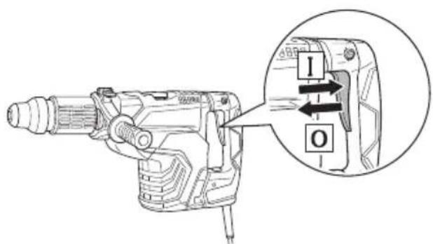
- Ensure that the power switch is in the OFF position.
If the plug is connected to a receptacle while the power switch is in the ON position, the power tool will start operating immediately, which could cause a serious accident.
- When the work area is removed from the power source, use an extension cord of sufficient thickness and rated capacity. The extension cord should be kept as short as practicable.
- Do not touch the bit during or immediately after operation. The bit becomes very hot during operation and could cause serious burns.
- Before starting to break, chip or drill into a wall, floor or ceiling, thoroughly confi rm that such items as electric cables or conduits are not buried inside.
- Always hold the body handle and side handle of the power tool firmly. Otherwise the counterforce produced may result in inaccurate and even dangerous operation.
- Wear a dust mask.
Do not inhale the harmful dusts generated in drilling or chiseling operation. The dust can endanger the health of yourself and bystanders.
- Mounting the tool
To prevent accidents, make sure to turn the switch off and disconnect the plug from the receptacle.
When using tools such as bull points, drill bits, etc., make sure to use the genuine parts designated by our company.
○ Clean the shank portion of the drill bit. Then smear the shank portion with the grease or machine oil.
9. The rotation speed cannot be changed by pressing the rotation speed selector switch while the motor is rotating. To change speeds, switch off the tool first.
10. RCD
The use of a residual current device with a rated residual current of 30mA or less at all times is recommended.
SYMBOLS
WARNING
The following show symbols used for the machine. Be sure that you understand their meaning before use.

 | Read all safety warnings and all instructions. |
 | Only for EU countriesDo not dispose of electric tools together with household waste material!In observance of European Directive 2002/96/EC on waste electrical and electronic equipment and its implementation in accordance with national law, electric tools that have reached the end of their life must be collected separately and returned to an environmentally compatible recycling facility. |
 | Rated voltage |
| P | Power Input |
| (ZHZY) | No-load speed |
| Bpm Full-load impact rate | |
 | Drilling diameter, max. |
| Weight(According to EPTA-Procedure 01/2003) | |
 | Drill bit |
 | Core bit |
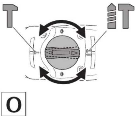
 | Adjustment of the tool position function |
 | Hammering only function |
| [73S3] | Rotation and hammering function |
 | Switching ON |
 | Switching OFF |
 | Continuous operation button |
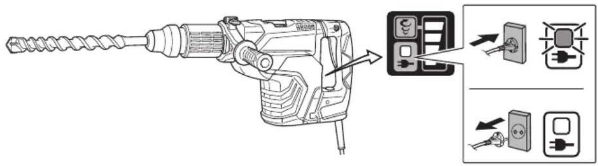
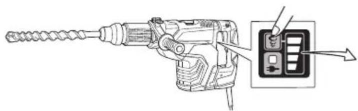
 | Power lamp |
 | Rotation speed selector switch |
 | Display lamp |
 | Low speed / impact rate |
 | High speed / impact rate |
 | Disconnect mains plug from electrical outlet |
 | Class II tool |
 | SDS max shank |
STANDARD ACCESSORIES
In addition to the main unit (1 unit), the package contains the accessories listed in the below.
○ Plastic case 1
○ Side handle 1
○ Stopper 1
○ Hammer Grease A 1
Standard accessories are subject to change without notice.
APPLICATIONS
Rotation and hammering function IT
○ Drilling anchor holes
○ Drilling holes in concrete
Hammering only function
○ Crushing concrete, chipping, digging, and squaring (by applying optional accessories)
SPECIFICATIONS
The specifications of this machine are listed in the Table on page 105.
NOTE
Due to HiKOKI's continuing program of research and development, the specifications herein are subject to change without prior notice.
MOUNTING AND OPERATION
| Action Figure Page | ||
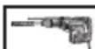
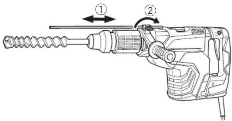
| Inserting SDS-max tools 1 106 | ||
| Removing SDS-max tools 2 106 | ||
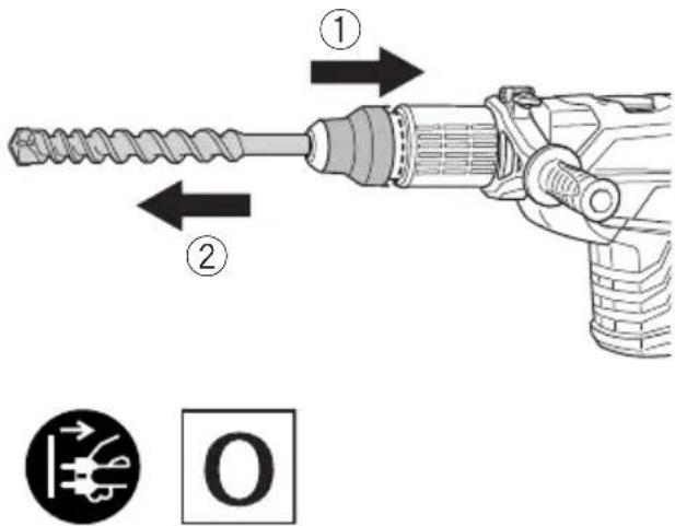
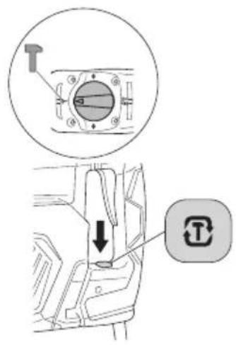
| Changing tool direction 3 106 | ||
| Selecting the operating mode 4 106 | ||
| Switching on and off | 5 | |
| About the power lamp 6 107 | ||
| Speed change 7 107 | ||
| Install the stopper | 8 107 | |
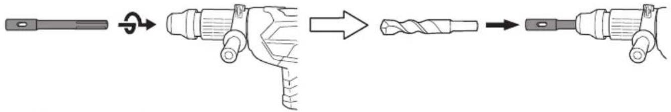
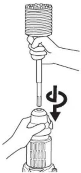
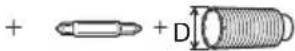
| Using tapershank adapter 9 | 108 | |
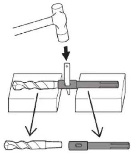
| Removing tapershank adapter | 10 | 108 |
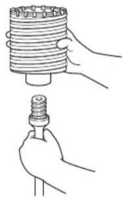
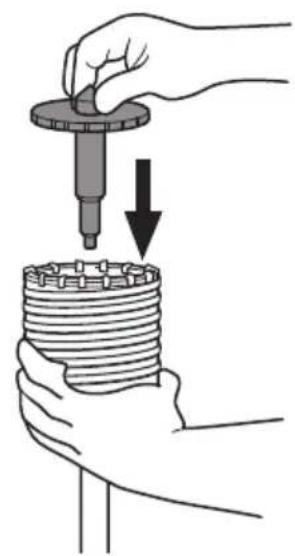
| Mounting core bit | 11 | 108 |
| Mounting guide plate and center pin | 12 | 108 |
| Selecting accessories* | - | 109, 110 |
* For detailed information regarding each tool, contact a HiKOKI authorized service center.
Warming up (Fig. 13)
The grease lubrication system in this unit may require warming up in cold regions.
Position the end of the bit so makes contact with the concrete, turn on the switch and perform the warming up operation. Make sure that a hitting sound is produced and then use the unit.
CAUTION
When the warming up operation is performed, hold the side handle and the main body securely with both hands to maintain a secure grip and be careful not to twist your body by the jammed drill bit.
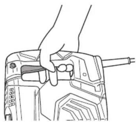
Using Continuous operation button
The Continuous operation button feature is only available for "Hammering Mode 1". Pressing the Continuous operation button will switch on a blue LED that indicates the activation of the Continuous operation function which will keep the tool running even after the trigger switch is released. To cancel the function, press the Continuous operation button again or push the trigger switch to the ON position. (Fig. 14)
NOTE
Continuous operation will be deactivated when the switch is pressed. During continuous operation, keep your hand away from the switch and grip the lower part of the handle to avoid any unintentional contact with the switch. (Fig.15)
ABOUT THE PROTECTION FUNCTION
This tool has a built-in protection circuit for preventing damage to the unit in the event of an abnormality. Depending on the nature of the abnormality, the display lamp will flash as shown in Table 1 and the unit will cease to operate. In such cases, verify the problem indicated by the flashing and take whatever steps are necessary to correct the problem.
NOTE
Repair may be required if the display lamp continues to flash after taking all necessary steps to correct the problem. If the problem persists, please arrange for repairs.
Table 1
| Display lamp fl ashing | Cause | Solution |
| Flash106 | Internal temperature has risen beyond the unit's specifi ed temperature. (Temperature increase protection function) | Turn off the unit and allow it to cool down for about 15 to 30 minutes. When the temperature goes down, press the rotation speed selector switch to recover. |
| Flash | Excessive pressure applied to the tool has resulted in an overload. (Overload protection function) | Press the rotation speed selector switch to recover. Try to avoid tasks that will apply excess pressure to the unit. |
| Flash | Tool is connected to a power source whose voltage is either too high or too low. (Circuit protection function) | Connect the unit to a power supply matching the input voltage specifi ed on the nameplate. Press the rotation speed selector switch to recover. |
| Flash | Sensor signal read error. (Control monitoring function) | Press the rotation speed selector switch to recover. Repair may be required if this error continuously occurs. |
GREASE REPLACEMENT
This Rotary Hammer is of full air-tight construction to protect against dust and to prevent lubricant leakage.
Therefore, this Rotary Hammer can be used without lubrication for long periods. Replace the grease as described below.
Grease Replacement Period
After purchase, replace grease after every 6 months of usage. Ask for grease replacement at the nearest authorized Service Center.
MAINTENANCE AND INSPECTION
1. Inspecting the drill bits
Since use of a dull tool will cause motor malfunctioning and degraded efficiency, replace the drill bit with new ones or resharpen them without delay when abrasion is noted.
2. Inspecting the mounting screws
Regularly inspect all mounting screws and ensure that they are properly tightened. Should any of the screws be loose, retighten them immediately. Failure to do so could result in serious hazard.
3. Maintenance of the motor
The motor unit winding is the very "heart" of the power tool.
Exercise due care to ensure the winding does not become damaged and/or wet with oil or water.
4. Replacing supply cord
If the replacement of the supply cord is necessary, this has to be done by the manufacturer of this agent in order to avoid a safety hazard.
CAUTION
In the operation and maintenance of power tools, the safety regulations and standards prescribed in each country must be observed.
GUARANTEE
We guarantee HiKOKI Power Tools in accordance with statutory/country specific regulation. This guarantee does not cover defects or damage due to misuse, abuse, or normal wear and tear. In case of complaint, please send the Power Tool, undismantled, with the GUARANTEE CERTIFICATE found at the end of this Handling instruction, to a HiKOKI Authorized Service Center.
IMPORTANT
Correct connection of the plug
The wires of the main lead are coloured in accordance with the following code:
Blue: — Neutral
Brown: — Live
As the colours of the wires in the main lead of this tool may not correspond with the coloured markings identifying the terminals in your plug proceed as follows:
The wire coloured blue must be connected to the terminal marked with the letter N or coloured black. The wire coloured brown must be connected to the terminal marked with the letter L or coloured red. Neither core must be connected to the earth terminal.
NOTE:
This requirement is provided according to BRITISH STANDARD 2769: 1984.
Therefore, the letter code and colour code may not be applicable to other markets except The United Kingdom.
Information concerning airborne noise and vibration
The measured values were determined according to EN60745 and declared in accordance with ISO 4871.
Measured A-weighted sound power level:
106 dB (A) (DH45ME)
107 dB (A) (DH45MEY)
Measured A-weighted sound pressure level:
95 dB (A) (DH45ME)
96 dB (A) (DH45MEY)
Uncertainty K: 3 dB (A).
Wear hearing protection.
Vibration total values (triax vector sum) determined according to EN60745.
Hammer drilling into concrete:
Vibration emission value ah, HD = 13.5 m/s ^2 (DH45ME) 8.8 m/s ^2 (DH45MEY)
Uncertainty K = 1.5 m/s ^4
Equivalent chiselling value:
Vibration emission value _h , CHeq = 14.2 m/s ^2 (DH45ME) 9.2 m/s ^2 (DH45MEY)
Uncertainty K = 1.5 m/s ^4
The declared vibration total value has been measured in accordance with a standard test method and may be used for comparing one tool with another.
It may also be used in a preliminary assessment of exposure.
WARNING
☐ The vibration emission during actual use of the power tool can differ from the declared total value depending in the ways in which the tool is used.
- Identify safety measures to protect the operator that are based on an estimation of exposure in the actual conditions of use (taking account of all parts of the operating cycle such as the times when the tool is switched off and when it is running idle in addition to the trigger time).
NOTE
Due to HiKOKI's continuing program of research and development, the specifications herein are subject to change without prior notice.
VEDLIKEHOLD OG INSPEKSJON
1. Inspisere boringsbitene
Negotovost K: 3 dB (A).
flowchart
graph TD
    A["Step 1: Screwdriver with two tools"] --> B["Step 2: Screwdriver with two tools"]
    B --> C["Step 3: Screwdriver with two tools"]
    C --> D["Step 4: Screwdriver with two tools"]
    D --> E["Step 5: Screwdriver with two tools"]
    E --> F["Final assembled: Screwdriver with no tool and circular head"]
2
3
4
5
6

7

| Ls Hs | |||||
| 110 V120 V127 V | n0 | 120 170 220 270 | |||
| Bpm | 1200 1600 2100 2500 | ||||
| 220 V230 V240 V | n0 | 120 180 240 310 | |||
| Bpm | 1200 1700 2300 2950 | ||||
8


9
flowchart
graph LR
    A["Start: Drill Bit"] --> B["Rotate to Twist Drill"]
    B --> C["Rotate to Drill"]
    C --> D["Rotate to Drill"]


10 11
natural_image
Illustration of two hands holding a cylindrical component and a spiral-shaped tool (no text or symbols)
natural_image
Illustration of hands using a screwdriver to press a cylindrical component with a downward arrow indicating rotation (no text or symbols)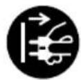

12 13
natural_image
Illustration of hands using a tool to adjust a cylindrical component (no text or symbols present)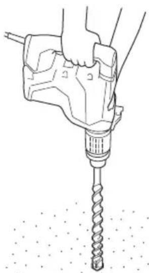
natural_image
Line drawing of a hand using a drill bit to drill a screw, with no text or symbols present.14 15
natural_image
Line drawing of a hand holding a drill bit with a tool, no text or symbols presentIT


956009 (D ≤ 35)
955165 (D ≥ 38)
natural_image
Line drawing of a manual drill bit with no text or symbols


321813

313468
930515


12,7 mm:313469
19,0 mm : 313470
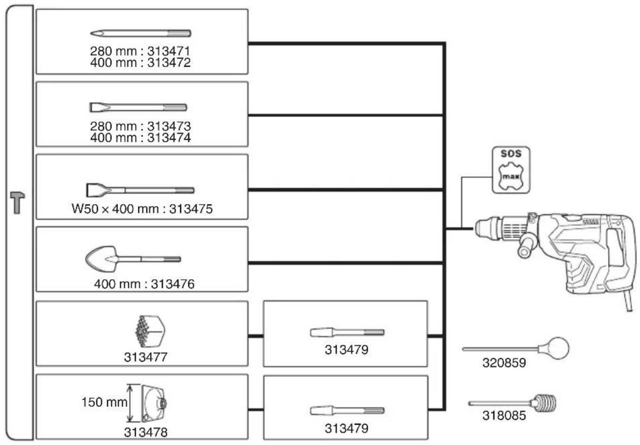
flowchart
graph TD
    A["280 mm : 313471\n400 mm : 313472"] --> B["W50 × 400 mm : 313475"]
    C["280 mm : 313473\n400 mm : 313474"] --> B
    D["400 mm : 313476"] --> E["313477"]
    F["150 mm"] --> G["313478"]
    H["313479"] --> I["313479"]
    J["SOS max"] --> K["Drill Tool"]
    L["320859"] --> K
    M["318085"] --> K
    B --> N["End"]
natural_image
Simple line drawing of a straight rod with no text or symbols
natural_image
Line drawing of a briefcase with handle and clasp (no text or symbols)| English Dansk Română | ||||
| GUARANTEE CERTIFICATE1 Model No.2 Serial No.3 Date of Purchase4 Customer Name and Address5 Dealer Name and Address(Please stamp dealer name and address) | GARANTIBEVIS1 Modelnummer2 Serienummer3 Købsdato4 Kundes navn og adresse5 Forhandlers navn og adresse(Indsæt stempel med forhandlers navn og adresse) | CERTIFICAT DE GARANTIE1 Model nr.2 Nr. de serie3 Data cumpărării4 Numele și adresa clientului5 Numele și adresa distribuitorului(Vă rugăm aplicați ștampila cu numele și adresa distribuitorului) | ||
| Deutsch Norsk Slovenščina | ||||
| GARANTIESCHEIN1 Modell-Nr.2 Serien-Nr.3 Kaufdatum4 Name und Anschrift des Kunden5 Name und Anschrift des Händlers(Bitte mit Namen und Anschrift des Handlers abstempeln) | GARANTISERTIFIKAT1 Modellnr.2 Serienr.3 Kjøpsdato4 Kundens navn og adresse5 Forhandlerens navn og adresse(Vennligst stemple forhandlerens navn og adresse) | GARANCIJSKO POTRDILO1 Št. modela2 Serijska št.3 Datum nakupa4 Ime in naslov kupca5 Ime in naslov prodajalca(Prosimo vtsnite žig z imenom in naslovom prodajalca) | ||
| Français Suomi Slovenčina | ||||
| CERTIFICAT DE GARANTIE1 No. de modèle2 No de série3 Date d'achat4 Nom et adresse du client5 Nom et adresse du revendeur(Cachet portant le nom et l'adresse du revendeur) | TAKUUTODISTUS1 Malli nro2 Sarja nro3 Ostopăivămâără4 Asiakkaan nimi ja osoite5 Myyjăn nimi ja osoite(Leimaa myyjăn nimi ja osoite) | ZÁRUČNÝ LISTA1 Č. modelu2 Sériové č.3 Dátum zakúpenia4 Meno a adresa zákaznika5 Názov a adresa predajcu(Pečiatka s názvom a adresou predajcu) | ||
| Italiano Eλληνικά Български | ||||
| CERTIFICATO DI GARANZIA1 Modello2 N° di serie3 Data di acquisto4 Nome e indirizzo dell'acquirente5 Nome e indirizzo del rivenditore(Si prega di apporre il timbro con questi dati) | ПІЗТОПОІНТИКО ЕГГУНЄНЗ1 Ар. Movtėlou2 Aŭξων Αρ.3 Нμερομηνία αγοράς4 ́Овома кой διεύθυνση πελάτη5 ́Овома кай διεύθυνση μεταπωλητή(Παρακαλούμε να χρησιμοποιηθεί σφραγίδα) | ГАРАНЦИОНЕН СЕРТИФИКАТ1 Модел No2 Сериен No3 Дата за закупуване4 Име и адрес на клиента5 Име и адрес на търговеца(Моля, отпечатайте името и адрес на дильра) | ||
| Nederlands Polski Srpski | ||||
| GARANTIEBEWIJS1 Modelnummer2 Serienummer3 Datum van aankoop4 Naam en adres van de gebruiker5 Naam en adres van de handelaar(Stempel a.u.b. naam en adres vande de handelaar) | GWARANCJA1 Model2 Numer seryjny3 Data zakupu4 Nazwa klienta i adres5 Nazwa dealera i adres(Pieczęć punktu sprzedaży) | GARANTNI SERTIFIKAT1 Br. modela.2 Serijski br.3 Datum kupovine4 Ime i adresa kupca5 Ime i adresa prodavca(Molimo da stavite pečat na ime i adresu trgovca) | ||
| Español Magyar Hrvatski | ||||
| CERTIFICADO DE GARANTÍA1 Número de modelo2 Número de serie3 Fecha de adquisición4 Nombre y dirección del cliente5 Nombre y dirección del distributor(Se ruega poner el sello del distribuidor con su nombre y dirección) | GARANCIA BIZONYLAT1 Tipusszám2 Sorozatszám3 A vásárlás dátuma4 A Vásárló neve és címe5 A Kereskedő neve és címe(Kárjük ide olhelyezni a Kereskedő nevének és címének pecsétjét) | JAMSTVENI CERTIFIKAT1 Br modela.2 Serijski br.3 Datum kupnje4 Ime i adresa kupca5 Ime i adresa trgovca(Molimo stavite pečat na ime i adresu trgovca) | ||
| Português Čeština Український | ||||
| CERTIFICADO DE GARANTIA1 Número do modelo2 Número do série3 Data de compra4 Nome e morada do cliente5 Nome e morada do distribuidor(Por favor, carimbe o nome e morada do distribuidor) | ZÁRUČNÍ LIST1 Model č.2 Série č.3 Datum nákupu4 Jméno a adresa zákazníka5 Jméno a adresa prodejce(Prosíme o razitko se jménem a adresou prodejce) | ГАРАНТИЙНИЙ СЕРТИФИКАТ1 No моделі2 No серії3 Дата придбання4 I'm'я і адреса клиента5 I'm'я і адреса дилера(Будь ласка, поставте печатку з іменем і адресою дилера) | ||
| Svenska Türkçe | Русский | |||
| GARANTICERTIFIKAT1 Modellnr2 Serienr3 Inköpsdatum4 Kundens namn och adress5 Försäljarens namn och adress(Stámpla försäljarens namn och adress) | GARANTI SERTÍFÍKASI1 Model No.2 Seri No.3 Satin Alma Tarihi4 Müşteri Adı ve Adresi5 Bayi Adı ve Adresi(Lütfen bayi adini ve adresini kaşe olarak basin) | ГАРАНТИЙНЫЙ СЕРТИФИКАТ1 Модель No2 Серийный No3 Дата покупки4 Название и адрес заказчика5 Название и адрес дилера(Пожалуйста, внесите название и адрес дилера) | ||

HiKOKI
| 1 | |
| 2 | |
| 3 | |
| 4 | |
| 5 |
Siemensring 34, 47877 willich, Germany
Tel: +49 2154 49930
Fax: +49 2154 499350
URL: http://www.hikoki-powertools.de
Hikoki Power Tools Netherlands B.V.
Brabanthaven 11, 3433 PJ Nieuwegein, The Netherlands
Tel: +31 30 6084040
Fax: +31 30 6067266
URL: http://www.hikoki-powertools.nl
Hikoki Power Tools (U.K.) Ltd.
Precedent Drive, Rooksley, Milton Keynes, MK 13, 8PJ, United Kingdom
Tel: +44 1908 660663
Fax: +44 1908 606642
URL: http://www.hikoki-powertools.uk
Hikoki Power Tools France S.A.S.
Hikoki Power Tools Belgium N.V./S.A.
Koningin Astridlaan 51, B-1780 Wemmel, Belgium
Tel: +32 2 460 1720
Fax: +32 2 460 2542
URL http://www.hikoki-powertools.be
Hikoki Power Tools Italia S.p.A
Via Piave 35, 36077, Altavilla Vicentina (VI), Italy
Tel: +39 0444 548111
Fax: +39 0444 548110
URL: http://www.hikoki-powertools.it
Hikoki Power Tools Ibérica, S.A.
C/ Puigbarral, 26-28, Pol. Ind. Can Petit, 08227 Terrassa
(Barcelona), Spain
Tel: +34 93 735 6722
Fax: +34 93 735 7442
URL: http://www.hikoki-powertools.es
Kjeller Vest 7, N-2007 Kjeller, Norway
Tel: (+47) 6692 6600
Fax: (+47) 6692 6650
URL: http://www.hikoki-powertools.no
Hikoki Power Tools Sweden AB
Rotebergsvagen 2B SE-192 78 Sollentuna, Sweden
Tel: (+46) 8 598 999 00
Fax: (+46) 8 598 999 40
URL: http://www.hikoki-powertools.se
Hikoki Power Tools Denmark A/S
Lillebaeltsvej 90, 6715 Esbjerg N, Denmark
Tel: (+45) 75 14 32 00
Fax: (+45) 75 14 36 66
URL: http://www.hikoki-powertools.dk
Hikoki Power Tools Finland Oy
Tupalankatu 9, 15680 Lahti, Finland
Tel: (+358) 20 7431 530
Fax: (+358) 20 7431 531
URL: http://www.hikoki-powertools.fi
Hikoki Power Tools Hungary Kft.
Hikoki Power Tools Romania S.R.L.
Ring Road, No. 66, Mustang Traco Warehouses, Warehouse
No.1, Pantelimon City, 077145, Ilfov County, Romania

- (Original instructions)
- GENERAL POWER TOOL SAFETY WARNINGS
- WARNING
- 1) Work area safety
- 2) Electrical safety
- 3) Personal safety
- 4) Power tool use and care
- 5) Service
- PRECAUTION
- ROTARY HAMMER SAFETY WARNINGS
- Wear ear protectors
- ADDITIONAL SAFETY WARNINGS
- SYMBOLS
- STANDARD ACCESSORIES
- In addition to the main unit (1 unit), the package contains the accessories listed in the below.
- APPLICATIONS
- Rotation and hammering function IT
- SPECIFICATIONS
- NOTE
- Warming up (Fig. 13)
- CAUTION
- Using Continuous operation button
- ABOUT THE PROTECTION FUNCTION
- GREASE REPLACEMENT
- Grease Replacement Period
- MAINTENANCE AND INSPECTION
- Inspecting the drill bits
- Inspecting the mounting screws
- Maintenance of the motor
- Replacing supply cord
- GUARANTEE
- IMPORTANT
- NOTE:
- Information concerning airborne noise and vibration
- VEDLIKEHOLD OG INSPEKSJON
- Inspisere boringsbitene
- Hikoki Power Tools Netherlands B.V.
- Hikoki Power Tools (U.K.) Ltd.
- Hikoki Power Tools France S.A.S.
- Hikoki Power Tools Belgium N.V./S.A.
- Hikoki Power Tools Italia S.p.A
- Hikoki Power Tools Ibérica, S.A.
- Hikoki Power Tools Sweden AB
- Hikoki Power Tools Denmark A/S
- Hikoki Power Tools Finland Oy
- Hikoki Power Tools Hungary Kft.
- Hikoki Power Tools Romania S.R.L.
Brand : HiKOKI
Model : DH45MEY
Category : Hammer