
H60MC(V) - Hammer HiKOKI - Free user manual and instructions
Find the device manual for free H60MC(V) HiKOKI in PDF.


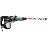
| Brand | HiKOKI |
| Model | H60MC(V) |
| Product Type | Demolition Hammer |
| Power Input | 1250 W |
| Voltage | 230 V~ (by area) |
| Full-Load Impact Rate | 900 – 1600 /min (stepless adjustment) |
| Weight | 11.3 kg |
| Shank Type | SDS-max |
| Standard Accessories | Carrying case, Bull Point (SDS-max), Side Handle |
| Optional Accessories | Bull Point (280/400 mm), Cutter, Bushing Tool, Rammer, Cold Chisel, Scoop, Hammer Grease A |
| Applications | Demolishing concrete, chipping, grooving, bar cutting, driving piles, piping/wiring installation |
| Tool Positioning | 360° rotatable, 12 positions (30° steps) |
| Side Handle | Adjustable 360° and fore-aft |
| Switch Type | Trigger switch with lock-on button for continuous operation |
| Grease Type | HiKOKI Electric Hammer Grease A (low viscosity) |
| Grease Capacity | 76 g (standard fill) |
| Carbon Brush Replacement | Auto-stop type; replace both when worn |
| Safety Features | Insulated gripping surfaces, ear protection recommended, anti-vibration side handle |
| Maintenance | Inspect mounting screws, clean carbon brushes, replace grease at brush change |
Frequently Asked Questions - H60MC(V) HiKOKI
User questions about H60MC(V) HiKOKI
0 question about this device. Answer the ones you know or ask your own.
Ask a new question about this device
Download the instructions for your Hammer in PDF format for free! Find your manual H60MC(V) - HiKOKI and take your electronic device back in hand. On this page are published all the documents necessary for the use of your device. H60MC(V) by HiKOKI.
USER MANUAL H60MC(V) HiKOKI
natural_image
Line drawing of a handheld drill bit with a circular outline (no text or symbols)
Read through carefully and understand these instructions before use.
使用前務請詳加閱讀
natural_image
Illustration of a hand using a screwdriver to lift a tool, with an arrow indicating direction (no text or symbols present)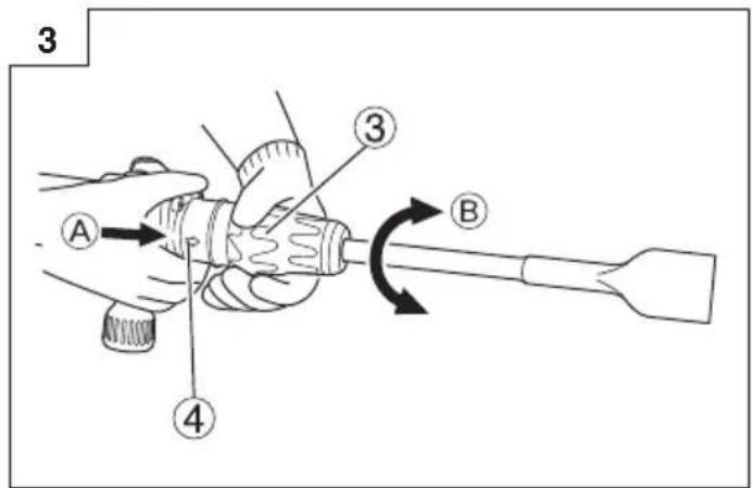
natural_image
Line drawing of a hand gripping a tool with a curved handle and directional arrow (no text or symbols)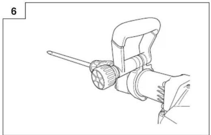
natural_image
Line drawing of a mechanical tool with a wrench and handle (no text or symbols)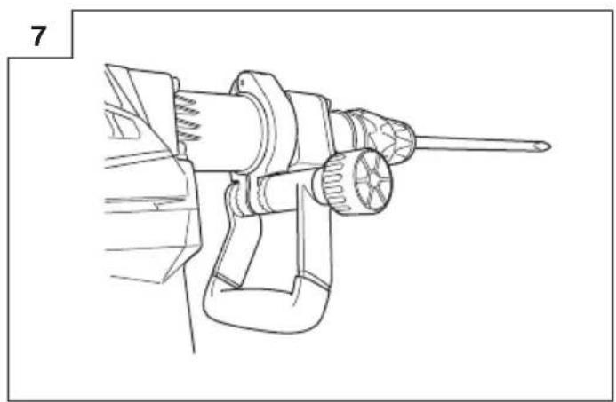
natural_image
Line drawing of a mechanical tool with a pointed tip and handle (no text or symbols)8
9
natural_image
Line drawing of a hand operating a drill bit with a tool, no text or symbols present10
natural_image
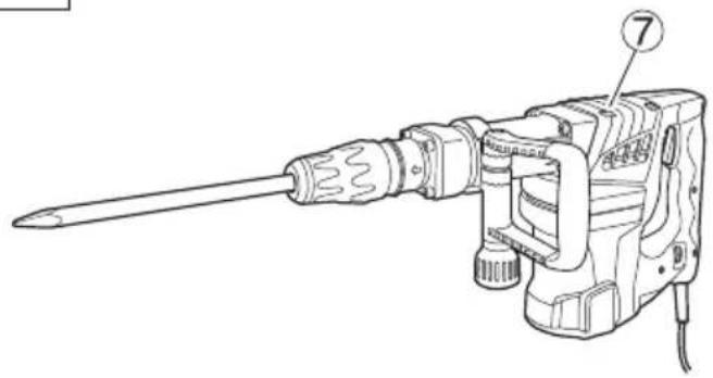
Line drawing of a drill bit with labeled component (7), no text or symbols present11
Read all safety warnings and all instructions.
Failure to follow the warnings and instructions may result in electric shock, fire and/or serious injury.
Save all warnings and instructions for future reference.
The term “power tool” in the warnings refers to your mains-operated (corded) power tool or battery-operated (cordless) power tool.
1) Work area safety
a) Keep work area clean and well lit.
Cluttered and dark areas invite accidents.
b) Do not operate power tools in explosive atmospheres, such as in the presence of fl ammable liquids, gases or dust.
Power tools create sparks which may ignite the dust of fumes.
c) Keep children and bystanders away while operating a power tool.
Distractions can cause you to lose control.
2) Electrical safety
a) Power tool plugs must match the outlet.
Never modify the plug in any way.
Do not use any adapter plugs with earthed (grounded) power tools.
Unmodifi ed plugs and matching outlets will reduce risk of electric shock.
b) Avoid body contact with earthed or grounded surfaces such as pipes, radiators, ranges and refrigerators.
There is an increased risk of electric shock if your body is earthed or grounded.
c) Do not expose power tools to rain or wet conditions.
Water entering a power tool will increase the risk of electric shock.
d) Do not abuse the cord. Never use the cord for carrying, pulling or unplugging the power tool.
Keep cord away from heat, oil, sharp edges or moving parts.
Damaged or entangled cords increase the risk of electric shock.
e) When operating a power tool outdoors, use an extension cord suitable for outdoor use.
Use of a cord suitable for outdoor use reduces the risk of electric shock.
f) If operating a power tool in a damp location is unavoidable, use a residual current device (RCD) protected supply.
Use of an RCD reduces the risk of electric shock.
3) Personal safety
a) Stay alert, watch what you are doing and use common sense when operating a power tool.
Do not use a power tool while you are tired or under the influence of drugs, alcohol or medication.
A moment of inattention while operating power tools may result in serious personal injury.
b) Use personal protective equipment. Always wear eye protection.
Protective equipment such as dust mask, non-skid safety shoes, hard hat, or hearing protection for appropriate conditions will reduce personal injuries.
c) Prevent unintentional starting. Ensure the switch is in the off position before connecting to power source and/or battery pack, picking up or carrying the tool.
Carrying power tools with your finger on the switch or energising power tools that have the switch on invites accidents.
d) Remove any adjusting key or wrench before turning the power tool on.
A wrench or a key left attached to a rotating part of the power tool may result in personal injury.
e) Do not overreach. Keep proper footing and balance at all times.
This enables better control of the power tool in unexpected situations.
f) Dress properly. Do not wear loose clothing or jewellery. Keep your hair, clothing and gloves away from moving parts.
Loose clothes, jewellery or long hair can be caught in moving parts.
g) If devices are provided for the connection of dust extraction and collection facilities, ensure these are connected and properly used.
Use of these devices can reduce dust related hazards.
4) Power tool use and care
a) Do not force the power tool. Use the correct power tool for your application.
The correct power tool will do the job better and safer at the rate for which it was designed.
b) Do not use the power tool if the switch does not turn it on and off.
Any power tool that cannot be controlled with the switch is dangerous and must be repaired.
c) Disconnect the plug from the power source before making any adjustments, changing accessories, or storing power tools.
Such preventive safety measures reduce the risk of starting the power tool accidentally.
d) Store idle power tools out of the reach of children and do not allow persons unfamiliar with the power tool or these instructions to operate the power tool.
Power tools are dangerous in the hands of untrained users.
e) Maintain power tools. Check for misalignment or binding of moving parts, breakage of parts and any other condition that may affect the power tools' operation.
If damaged, have the power tool repaired before use.
Many accidents are caused by poorly maintained power tools.
f) Keep cutting tools sharp and clean.
Properly maintained cutting tools with sharp cutting edges are less likely to bind and are easier to control.
g) Use the power tool, accessories and tool bits etc., in accordance with these instructions and in the manner intended for the particular type of power tool, taking into account the working conditions and the work to be performed.
Use of the power tool for operations different from intended could result in a hazardous situation.
59eService
a) Have your power tool serviced by a qualified repair person using only identical replacement parts.
This will ensure that the safety of the power tool is maintained.
PRECAUTION
Keep children and infi rm persons away.
When not in use, tools should be stored out of reach of children and infi rm persons.
DEMOLITION HAMMER SAFETY WARNINGS
- Wear ear protectors
Exposure to noise can cause hearing loss.
- Use auxiliary handles supplied with the tool.
Loss of control can cause personal injury.
- Hold power tool by insulated gripping surfaces, when performing an operation where the cutting accessory may contact hidden wiring or its own cord.
Cutting accessory contacting a "live" wire may make exposed metal parts of the power tool "live" and could give the operator an electric shock.
- Do not touch the bit during or immediately after operation. The bit becomes very hot during operation and could cause serious burns.
- Before starting to break, chip or drill into a wall, floor or ceiling, thoroughly confirm that such items as electric cables or conduits are not buried inside.
- Wear a mask when turning your head upward.
- Properly set the bit holder.
- At the start of work, confirm screw tightening.
- When working at a highly elevated location, pay attention to articles and persons below.
- Wear protective shoes to protect your feet.
SPECIFICATIONS
| Voltage (by areas)* (230 V) | ~ |
| Power Input* 1250 W | |
| Full-load Impact Rate 900–1600 /min | |
| Weight 11.3 kg |
* Be sure to check the nameplate on product as it is subject to change by areas.
STANDARD ACCESSORIES
(1) Case 1
(2) Bull Point (SDS-max shank)....1
(3) Side Handle....1
Standard accessories are subject to change without notice.
OPTIONAL ACCESSORIES (sold separately)
○ Demolishing

(1) Bull Point
Overall Length: 280, 400 mm
○ Asphalt Cutting

(1) Cutter
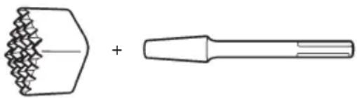
○ Surface Roughing
natural_image
Technical line drawing of a mechanical tool with a hexagonal base and a cylindrical handle (no text or symbols)(1) Bushing Tool
(2) Shank
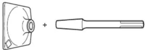
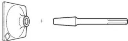
○ Tamping
natural_image
Technical line drawing of a mechanical component with a flanged shaft and circular housing (no text or symbols)(1) Rammer
(2) Shank
○ Groove digging and edging

(1) Cold chisel
Overall Length: 280, 400 mm
○ Scooping Work
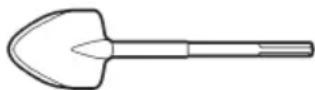
(1) Scoop
○ Hammer Grease A 500 g (in a can)
70 g (in a tube)
30 g (in a tube)
Optional accessories are subject to change without notice.
APPLICATIONS
Demolishing concrete, chipping off concrete, grooving, bar cutting, and driving piles.
Application examples:
Installation of piping and wiring, sanitary facility installation, machinery installation, water supply and drainage work, interior jobs, harbor facilities and other civil engineering work.
PRIOR TO OPERATION
1. Power source
Ensure that the power source to be utilized conforms to the power requirements specified on the product nameplate.
2. Power switch
Ensure that the power switch is in the OFF position. If the plug is connected to a receptacle while the power switch is in the ON position, the power tool will start operating immediately, which could cause a serious accident.
3. Extension cord
When the work area is removed from the power source, use an extension cord of sufficient thickness and rated capacity. The extension cord should be kept as short as practicable.
4. Installing tools
CAUTION
Be sure to switch power OFF and disconnect the plug from the receptacle to avoid serious trouble.
NOTE
When using tools such as bull points, make sure to use the genuine parts designated by our company.
(1) Clean the shank portion of the tool.
(2) As shown in Fig. 1, pull grip (A) in the direction of Ⓐ, and insert the tool into a hole of the front cap.
(3) Adjust the groove position while turning the tool, and furthermore insert it until it hits the end of the hole.
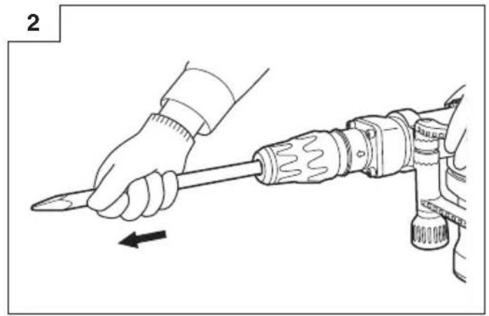
(4) Return grip (A) to its original position, pull the tool and make sure it is locked completely (Fig. 2).
5. Deciding Working Position of Tool
The tool can be turned every 30 degrees and can be fixed at the position of 12 steps.
(1) As shown in Fig. 3, if the grip (A) is turned in the direction of Ⓑ in a state where the grip (B) is pushed in the direction of Ⓐ, the blade angle can be changed freely to any desired position.
(2) Release grip (B) and turn the tool, and make sure that it is locked completely.
6. Removing Tool
As shown in Fig. 1, pull grip (A), and pull out the tool.
CAUTION
Be sure to grip the handle and side work. Do not hold by the grip (A) during work. If you pull it by mistake, the bull point could jump out.
7. Move the side handle
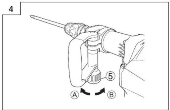
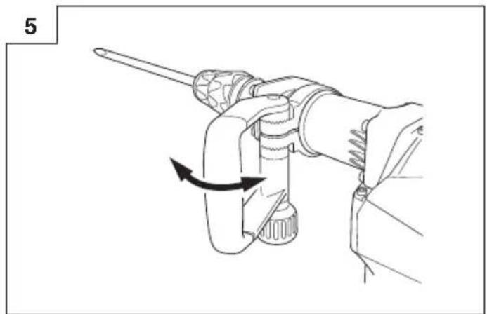
The side handle can be fi xed at any desired position; 360 degrees, and can also be fi xed at any position in the back-and-forth direction.
(1) Loosen the handle by turning the grip in the direction of Ⓐ as shown in Fig. 4.
(2) Adjust it to a position where vertical (up-and-down) operation can be facilitated as illustrated in Fig. 5, Fig. 6, and Fig. 7.
(3) Turn the grip in the direction of Ⓑ and fi x the handle.
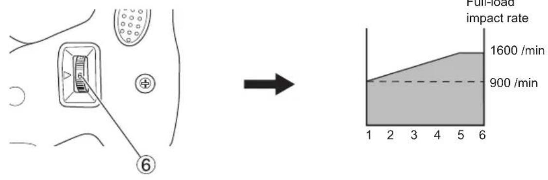
8. Select the number of strikes (Fig. 8)
CAUTION: Do not make any adjustment of the dial during operation. Holding the main body with one hand can swing you around, resulting in an injury.
This machine has an electronic controlled circuit built-in, enabling stepless regulation of the number of strikes. Make the most of this machine by adjusting the dial according to the working contents; chiseling, demolishing, or the quality of the material to be chiseling or demolishing.
The scale "1" of the dial is for the minimum speed with 900 strikes per minute, and the scale "6" is for the maximum speed with 1600 strikes per minute.
Standard number of strikes
| Dial | Number of strikes/min. |
| 6 | 1600 |
| 5 | 1600 |
| 4 | 1500 |
| 3 | 1300 |
| 2 | 1100 |
| 1 | 900 |
* The number of strikes on dials 5 and 6 is almost the same, but it is not a malfunction.
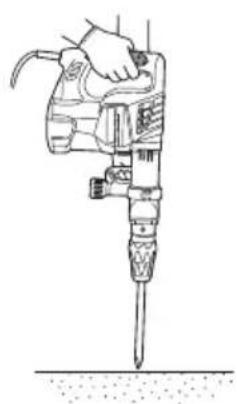
HOW TO USE THE DEMOLITION HAMMER (Fig. 9)
d.u After placing the tip of the tool on concrete surface, switch ON.
The switch can be turned ON if the trigger is pulled and OFF when it is released.
If the stopper is pressed while the trigger for the switch is pulled, even if your finger is released from the trigger, the switch remains ON - convenient for continuous operation.
To turn the switch OFF, pull the trigger again, and then the stopper comes off.
- By utilizing the empty weight of the machine and by firmly holding the demolition hammer with both hands, one can effectively control the subsequent recoil motion.
Proceed at a moderate work-rate, the use of too much force will impair efficiency.
CAUTION
After long time of use, the cylinder case becomes hot. Therefore, be careful not to burn your hands.
GREASE REPLACEMENT
This machine is of full air-tight construction to protect against dust and to prevent lubricant leakage. This machine can be used without grease supplement for an extended period of time. However, perform the grease replacement to maintain the service life. Replace the grease as described below.
1. Grease replacement period
You should look at the grease when you change the carbon brush. (See the section MAINTENANCE AND INSPECTION.) Ask for grease replacement at the nearest authorized HiKOKI Service Center.
In the case that you are forced to change the grease by yourself, please follow the following points.
2. How to replace grease
CAUTION
Before replacing the grease, turn the power off and pull out the plug from the receptacle.
(1) Remove the crank cover and wipe off the old grease inside. (Fig. 10)
(2) Supply 76 g (the standard volume to cover the connecting rod) of HiKOKI Electric Hammer Grease A to the crank case.
(3) After replacing the grease, install the crank cover securely. At this time, do not damage or lose the oil seal.
NOTE
The HiKOKI Electric Hammer Grease A is of the low viscosity type. When the grease is consumed, purchase from an authorized HiKOKI Service Center.
MAINTENANCE AND INSPECTION
CAUTION
Be sure to switch power OFF and disconnect the plug from the receptacle to avoid serious trouble.
1. Inspecting the tool
Since use of a dull tool will degrade efficiency and cause possible motor malfunction, sharpen or replace the tool as soon as abrasion is noted.
2. Inspecting the mounting screws
Regularly inspect all mounting screws and ensure that they are properly tightened. Should any of the screws be loose, retighten them immediately. Failure to do so could result in serious hazard.
3. Maintenance of the motor
The motor unit winding is the very “heart” of the power tool. Exercise due care to ensure the winding does not become damaged and/or wet with oil or water.
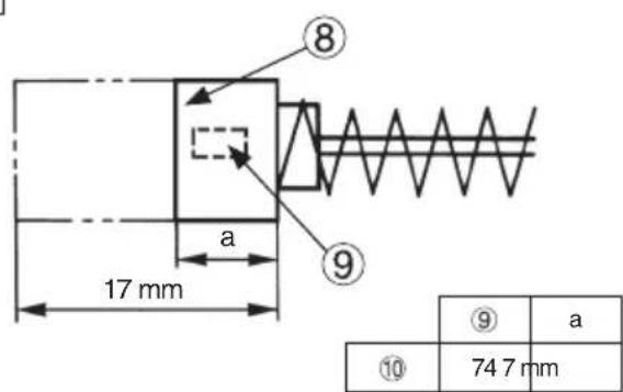
4. Inspecting the carbon brushes (Fig. 11)
The Motor employs carbon brushes which are consumable parts. When they become worn to or near the “wear limit”, it could result in motor trouble. When an auto-stop carbon brush is equipped, the motor will stop automatically. At that time, replace both carbon brushes with new ones which have the same carbon brush Numbers shown in the figure. In addition, always keep carbon brushes clean and ensure that they slide freely within the brush holders.
5. Replacing carbon brushes
Loosen the set screw and remove the tail cover. Remove the brush caps and carbon brushes. After replacing the carbon brushes, do not forget to tighten the brush caps securely and to install the tail cover.
CAUTION
In the operation and maintenance of power tools, the safety regulations and standards prescribed in each country must be observed.
NOTE
Due to HiKOKI's continuing program of research and development, the specifications herein are subject to change without prior notice.
一般安全規則
警告
閱讀所有安全警告說明
natural_image
Technical line drawing of a mechanical tool with two views: one showing a zigzag edge and the other a conical tool (no text or symbols)(1) 套筒 (2) 柄
○ 夯具
natural_image
Technical line drawing of a mechanical component with a flanged shaft and circular housing (no text or symbols)(1) 撞錘 (2) 柄
○ 開槽和飾邊
SquaredDeviation Trustee in the Applicable
natural_image
Line drawing of a quill pen in an inkwell (no text or symbols)
natural_image
Line drawing of a quill pen in an inkwell (no text or symbols)
natural_image
Line drawing of a quill pen with inkwell (no text or symbols)Koki Holdings Co., Ltd.
Shinagawa Intercity Tower A, 15-1, Konan 2-chome, Minato-ku, Tokyo, Japan
- 59eService
- PRECAUTION
- DEMOLITION HAMMER SAFETY WARNINGS
- STANDARD ACCESSORIES
- OPTIONAL ACCESSORIES (sold separately)
- APPLICATIONS
- PRIOR TO OPERATION
- Power source
- Power switch
- Extension cord
- Installing tools
- CAUTION
- NOTE
- Deciding Working Position of Tool
- Removing Tool
- Move the side handle
- Select the number of strikes (Fig. 8)
- HOW TO USE THE DEMOLITION HAMMER (Fig. 9)
- GREASE REPLACEMENT
- Grease replacement period
- How to replace grease
- MAINTENANCE AND INSPECTION
- Inspecting the tool
- Inspecting the mounting screws
- Maintenance of the motor
- Inspecting the carbon brushes (Fig. 11)
- Replacing carbon brushes
- 一般安全規則
- 警告
- Koki Holdings Co., Ltd.
Brand : HiKOKI
Model : H60MC(V)
Category : Hammer