
CIS642SCTT/1 - Cooker CANDY - Free user manual and instructions
Find the device manual for free CIS642SCTT/1 CANDY in PDF.
| Product Type | Built-in induction hob |
| Brand | Candy |
| Model | CIS642SCTT/1 |
| Number of cooking zones | 4 |
| Product dimensions (W×D×H) | 590 × 520 × 60 mm |
| Built-in dimensions (W×D) | 560 × 490 mm |
| Net weight | Approximately 10 kg |
| Electrical supply | 220-240 V ~ 50-60 Hz |
| Maximum installed power | 7.4 kW (adjustable from 2.5 to 7.4 kW) |
| Boost function | Yes – maximum power for 5 minutes per zone |
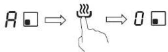
| Keep warm function | Yes – maintains stable temperature (display 'A') |
| Pause function (Stop+Go) | Yes – interrupts and resumes cooking |
| Timer | Up to 99 minutes, with automatic zone shut-off |
| Child lock | Yes – locks touch controls (display 'Lo') |
| Pan detection | Automatic – stops if pan is absent or unsuitable |
| Overheating protection | Yes – automatic shut-off in case of excessive temperature |
| Spill protection | Yes – stops in 10 seconds if liquid on controls |
| Automatic safety shut-off | Yes – according to power level (from 2 to 8 hours) |
| Cleaning | Ceramic glass surface – specific cleaner and scraper for sugary residues |
| Spare parts and repairability | Parts available via Candy after-sales service – repair by qualified technician |
| General information | Induction hob, 4 cooking zones, touch controls, digital display |
Frequently Asked Questions - CIS642SCTT/1 CANDY
User questions about CIS642SCTT/1 CANDY
0 question about this device. Answer the ones you know or ask your own.
Ask a new question about this device
Download the instructions for your Cooker in PDF format for free! Find your manual CIS642SCTT/1 - CANDY and take your electronic device back in hand. On this page are published all the documents necessary for the use of your device. CIS642SCTT/1 by CANDY.
USER MANUAL CIS642SCTT/1 CANDY
natural_image
Three white circles on a black background, no text or symbols visible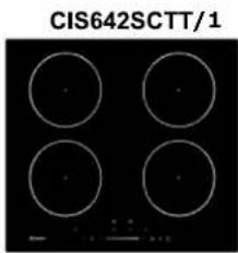
natural_image
Four white circles arranged in a 2x2 grid on a black background, labeled 'CIS642SCTT/1' at top (no other text or symbols)Thank you for purchasing the CANDY induction hob. Please read this instruction manual carefully before using the hob and keep it in a safe place for future reference.
Safety Warnings
Your safety is important to us. Please read information before using your cooktop.
Installation
Electrical Shock Hazard
- Disconnect the appliance from the mains electricity supply before carrying out any \ or maintenance on it.
- Connection to a good earth wiring system essential and mandatory.
• Alterations to the domestic wiring system only be made by a qualified electrician. - Failure to follow this advice may result in electrical shock or death.
Cut Hazard
• Take care - panel edges are sharp.
- Failure to use caution could result in inju cuts.
Important safety instructions
- Read these instructions carefully before installing or using this appliance.
- No combustible material or products should
placed on this appliance at any time.
- Please make this information available to person responsible for installing the appliance as it could reduce your installation costs.
- In order to avoid a hazard, this appliance be installed according to these instructions installation.
- This appliance is to be properly installed earthed only by a suitably qualified person
- This appliance should be connected to a which incorporates an isolating switch providing full disconnection from the power supply.
- Failure to install the appliance correctly c invalidate any warranty or liability claims.
Operation and maintenance
Electrical Shock Hazard
- Do not cook on a broken or cracked co the cooktop surface should break or crack, the appliance off immediately at the mains supply (wall switch) and contact a qualified technician.
- Switch the cooktop off at the wall before cleaning or maintenance.
- Failure to follow this advice may result in electrical shock or death.
Health Hazard
• This appliance complies with electromagneti
safety standards.
- However, persons with cardiac pacemakers other electrical implants (such as insulin pumps) must consult with their doctor or implant manufacturer before using this appliance to make sure that their implants not be affected by the electromagnetic field
- Failure to follow this advice may result i
Hot Surface Hazard
- During use, accessible parts of this appliance will become hot enough to cause burns.
- Do not let your body, clothing or any it than suitable cookware contact the Inductic glass until the surface is cool.
- Metallic objects such as knives, forks, spots and lids should not be placed on the hob since they can get hot
- Keep children away.
- Handles of saucepans may be hot to touch. Check saucepan handles do not overhang or cooking zones that are on. Keep handles of reach of children.
- Failure to follow this advice could result burns and scalds.
Cut Hazard
- The razor-sharp blade of a cooktop scrap exposed when the safety cover is retracted. with extreme care and always store safely out of reach of children.
- Failure to use caution could result in inju cuts.
Important safety instructions
- Never leave the appliance unattended whe use. Boilover causes smoking and greasy spillovers that may ignite.
- Never use your appliance as a work or surface.
- Never leave any objects or utensils on t appliance.
- Do not place or leave any magnetisable (e.g. credit cards, memory cards) or electronic devices (e.g. computers, MP3 players) near appliance, as they may be affected by its electromagnetic field.
- Never use your appliance for warming or heating the room.
- After use, always turn off the cooking zo and the cooktop as described in this manual by using the touch controls). Do not rely (pan detection feature to turn off the cooking zones when you remove the pans.
- Do not allow children to play with the a or sit, stand, or climb on it.
- Do not store items of interest to children cabinets above the appliance. Children climb on the cooktop could be seriously injured.
- Do not leave children alone or unattended the area where the appliance is in use.
• Children or persons with a disability which limits their ability to use the appliance show
have a responsible and competent person to instruct them in its use. The instructor should be satisfied that they can use the appliance with danger to themselves or their surroundings.
- Do not repair or replace any part of the appliance unless specifically recommended in manual. All other servicing should be done qualified technician.
- Do not use a steam cleaner to clean your cooktop.
- Do not place or drop heavy objects on cooktop.
- Do not stand on your cooktop.
- Do not use pans with jagged edges or across the Induction glass surface as this scratch the glass.
- Do not use scourers or any other harsh abrasive cleaning agents to clean your cocs as these can scratch the Induction glass.
- If the supply cord is damaged, it must replaced by the manufacturer, its service ag or similarly qualified persons in order to av hazard.
- This appliance is intended to be used in household and similar applications such as: -staff kitchen areas in shops, offices and working environments; -farm houses; -by clients in hotels, motels and other resident type environments; -bed and breakfast type environments.
- WARNING: The appliance and its accessible parts become hot during use.
Care should be taken to avoid touching head elements.
Children less than 8 years of age shall be away unless continuously supervised.
- This appliance can be used by children ag from 8 years and above and persons with reduced physical, sensory or mental capabiliti or lack of experience and knowledge if they been given supervision or instruction concern use of the appliance in a safe way and understand the hazards involved.
- Children shall not play with the appliance. Cleaning and user maintenance shall not be made by children without supervision.
- WARNING: Unattended cooking on a hob w fat or oil can be dangerous and may resul NEVER try to extinguish a fire with water, switch off the appliance and then cover flar with a lid or a fire blanket.
- WARNING: Danger of fire: do not store it the cooking surfaces.
- Warning: If the surface is cracked, switch the appliance to avoid the possibility of ele shock, for hob surfaces of glass-ceramic or similar material which protect live parts
- A steam cleaner is not to be used.
- The appliance is not intended to be operational means of an external timer or separate remote-control system.
CAUTION: The cooking process has to be supervised. A short term cooking process has be supervised continuously.
WARNING: In order to prevent tipping of the appliance, this stabilizing means must be installed. Refer to the instructions for installation.
WARNING: Use only hob guards designed by the manufacturer of the cooking appliance or indicated by the manufacture of the appliance in the instruction for use as suitable or hob guard incorporated in the appliance. The use of inappropriate guards can cause accidents.
This appliance incorporates an earth connection for functional purposes only.
Product Overview to Top View
Model: CIS633SCTT/1
text_image
1 2 3 4 51.2000 W zone, boost to 260DW
2.1500 W zone, boost to 2000W
3.2300 W zone, boost to 300Dw
-
Glass plate
-
Control panel
Model: CIS642SCTT/1
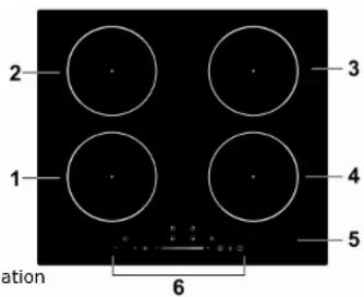
text_image
2 3 1 4 5 nation 61.2000 W ze, boost to 2600W
2.1500 W zone, boost to 2000W
3.2000 W zone, boost to 2600W
4.1500 W zone, boost to 2000W
-
Glass plate
-
Control panel
Congratulations on the purchase of your new Induction Hob.
We recommend that you spend some time to read this Instruction / Installation Manual in order to fully understand how to install correctly and operate it. For installation, please read the installation section.
Read all the safety instructions carefully before use and keep this Instruction / Installation Manual for future reference.
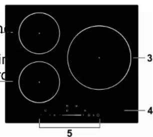
Control Pael
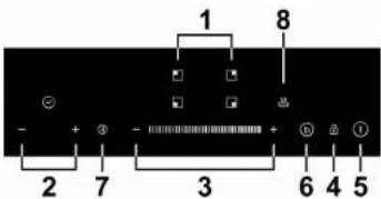
Model: CIS633SCTT/1
text_image
1 8 - + - 3 6 4 5 2 7- Heating one selection controls
- Timer control
- Power regulating key
- keylock control
- ON/OFF control
- Boost function control
- Stop and go function control
- Keep warm function control
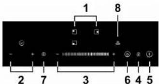
Model: CIS642SCTT/1
text_image
1 8 - + - - 3 6 4 5 2 7- Heating one selection controls
- Timer control
- Power regulating key
- keylock control
- ON/OFF control
- Boost function control
- Stop and go function control
- Keep warm function control
A Word on direction Cooking
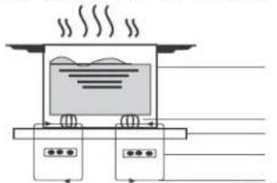
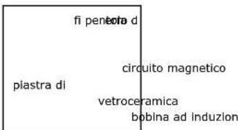
Induction cooking is a safe, advanced, efficient, and economical cooking technology. It works by electromagnetic vibrations generating heat directly pan, rather than indirectly through heating the glass surface. The glass hot only because the pan eventually warms it up.
natural_image
Simple line drawing of a steaming appliance with steam rising, no text or symbols presentEN-9
iron pot
magnetic circuit ceramic glass plate induction coil Induced currents
Before usig your New Induction Hob
- Read this guide, taking special note of the 'Safety Warnings' section.
- Remove any protective film that may still be on your Induction hob.
- Read this guide, taking special note of the 'Safety Warnings' section. - Remove any protective film that may still be on your Induction hob.
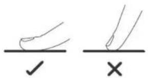
Using the Touch Controls
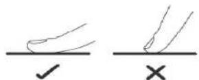
• The controls respond to touch, so you don't need to apply any pressure
- Use the ball of your finger, not its tip.
- You will hear a beep each time a touch is registered.
- Make sure the controls are always clean, dry, and that there is no ot utensil or a cloth) covering them. Even a thin film of water may make controls difficult to operate.
text_image
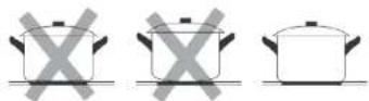
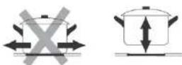
Diagram showing two hand-drawn symbols: a checkmark and a cross, likely indicating correct or incorrect conditions.Choosing the right Cookware

- Only use cookware with a base suitable for induction
cooking. Look for the induction symbol on the packaging or on the bottom of the pan.
-
You can check whether your cookware is suitable by carrying out a magnet test. Move a magnet towards the base of the pan. If it is attracted, the pan is suitable for induction.
• If you do not have a magnet: -
Put some water in the pan you want to check.
-
IE does not flash in the display and the water is heating, the pan is suitable.
- Cookware made from the following materials is not suitable: pure stainless steel, alumin copper without a magnetic base, glass, wood, porcelain, ceramic, and earthenware.
Do not use cookware with jagged edges or a curved base.
EN-10
Make sure that base of your pan is smooth, sits flat against the glass, and is
the same size as the cooking zone. Use pans whose diameter is as large as the Using
graphic of the zone selected. Using a pot a slightly wider energy will be used at its
maximum efficiency. If you use smaller pot efficiency could be less than expected
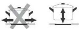
Always centre your pan on the cooking zone.
natural_image
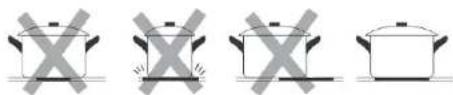
Four identical cooking pots with crossed X marks, no text or symbols presentAlways lift pans off the Induction hob - do not slide, or they may scratch
Pan dimensions
Using you Induction Hob
To start cooking
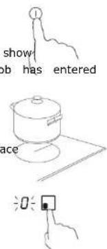
- Touch the ON/OFF control.
After power on, the buzzer beeps once, all displays show " - " or " - - ", indicating that the induction hob has entered the state of standby mode.
- Place a suitable pan on the cooking zone that the glass you wish to use.
• Make sure the bottom of the pan and the surface of the cooking zone are clean and dry.
- Touching the heating zone selection control, and a indicator next to the key will flash.
text_image
show job has entered place 0The cooking zones are up to a limit, automatically adapted to the diameter of the
pan. However the bottom of this pan must have a minimum of diameter according to a powlevel by touching the "-" " + ", or slide along the "-" control to the corresponding cooking zone. To obtain the best efficiency of your hob, or just touch any point of the "-"
please place the pan in the centre of the cooking zone.
The base diameter of induction cookware
Model: CIS633SCTT/1
| Cooking zone Minimum (mm) | |
| 1,2(180mm) 120 | |
| 3 (280mm) 180 | |
Model: CIS62SCTT/1
| Cooking zone Minimum (mm) | |
| 1, 2 , 3(180mm) | 120 |
The above may vary according to the quality of the pan used.
EN-11
text_image
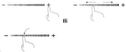
- Or - Ora. If you @onselect a heat zone within 1 minute, the ceramic hob will automatically switch off. You will need to start again at step 1. b. You can modify the heat setting at any time during cooking.
c. If slide along the “—”, power will vary from stage 2 to stage 8. Press “-”, power will decrease by one stage each time till stage 0. Press “+”, power will increase by one stage each time till stage 9.
EN-12
If the display flashes alternately with the heat setting
This means that:
- you have not placed a pan on the correct cooking zone or,
- the pan you're using is not suitable for induction cooking or,
- the pan is too small or not properly centred on the cooking zone.
No heating takes place unless there is a suitable pan on the cooking zone. that The display will automatically turn off after 1 minutes if no suitable pan is placed on it.
- Turn thehole cooktop off by touching the ON/OFF control.
- Beware of hot surfaces
'H' will show which cooking zone is hot to touch. It will disappear wh surface has cooled down to a safe temperature. It can also be used a energy saving function if you want to heat further pans, use the hotpl that is still hot.

When you have finished cooking
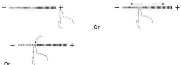
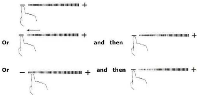
- Touching the heating zone selection control that you wish to switch off.

- Turn theooking zone off by touching the "-"and scrolling down to "0". Or slide along the "-" to the left point, and then touch the "-" Or touch the left point of "-" , and then touching the "-" .
text_image
Or and then Or and thenMake sure the power display shows "0", then shows "H".

and then

EN-13
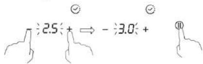
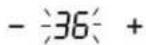
Using the oRver Management
Using power management you can set the total power to 2.5kW/ 3.0kW/ 5kW and 6.9kW for model CIS633SCTT/1, 2.5kW/ 3.0kW/ 4.5kW/ 6.5kW and 7.4kW for model CIS642SCTT/1. The default total power setting is the ma power level.
Setting the total power level to fit your requireme
- Make sure the cooktop is turned off.
Note: you can only set power management when the cooktop is turned o - Touch the button "Stop + Go" and hold for 5 seconds. You the buzzer beeps one time.
- After wo hear the beep, touch "+" and "-" button at the same time a 3 second, the timer indicator will show flashing previous total power level, '2.5'. Touch and hold "+" and "-" for 1 second again to switch to oth for example 3.0. When the power that you want is flashing, touch the b "Stop+Go" and hold for 5 seconds. The buzzer will beep 10 times. It me have finished the setting.

text_image
÷2.5÷+ ⇔ -÷3.0÷+ ⏱EN-14
Note:
- After step 2, you must touch the "+" and "-" within 3 seconds a the beep. Otherwise you will need to start again from step 2.
- Once finish setting, wait till the end of 10 beeps. Do not touch any this period. Otherwise the setting will be invalid.
Power management Rules
If total power exceeds the limitation of 2.5kw, 3.0kw, 4.5kw, 5.5kw or (depending on which level you've set), you are not able to increase power any zone. If you increase it by touching '+', the cooktop will beep 3 l indicator will show a flashing 'Pn'. Thus you need to decrease power station zones before increasing the power of objective zone.
Using the Boost
Boost is the function that one zone rising to a larger power in one se lasting for 5 minutes. Thus you can get a more powerful and faster co
Using the Boost to get larger power
- Touch the heating zone selection button that you boost, an indicator next to the key will flash.

- Touch the Boost button, the heating zone will begin to work at Book: The power display will show "P" to indicate that the zone is boosting
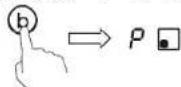
- The Boost power will last for 5 minutes and then the zone will go power stage 9.

- If you want to cancel the Boost during this 5 minutes, touch the h selection button, an indicator next to the key will flash. And then to EN-15
Boost button, the heating zone will go back to the power stage 9. Or slide along the “—” to the left point, the heating zone will go back to the | stage in which you touched.
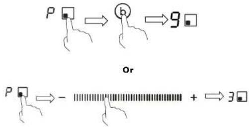
text_image
P → ⓑ → 9 Or P → - + → 3Restrictions when using
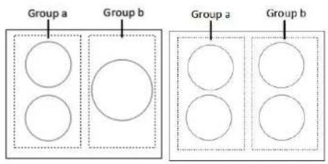
The three or four zones were divided into two groups. In one group, if one zone, first make sure that the other zone is working on/below pow
text_image
Group a Group b Group a Group bUsing the Keep warm
Keep warm function is suitable for keeping food warm. EN-16
Using the kεp warm to get stable temperature
- Touch theating zone selection button that you use keep warm, an indicator next to the key

Touch the ton 🎨, the cooking zone indicator will display "A".
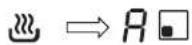
- If you want to cancel the keep warm, touch the heating zone selection and then touch the button. The heating zone will go back to "0" power stage.
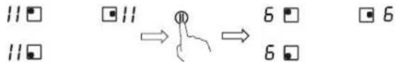
Using the Pause function- STOP+GO
Pause function can be used at any time during cooking. It allows to stop induction cooktop and come back to it.
- Make sure the cook zone is working.
- Touch the button STOP+GO, the cooking zone indicator will show "II". And then the operation of the induction cooktop will be deactivate within the of all cooking zones, except the STOP+GO, on/off and lock keys.
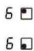
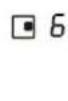

- To cancel the pause status, touch the button STOP+GO, then the cooking will go back to the power stage which you set before.
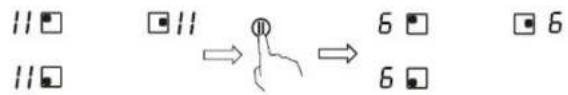
text_image
11□ 11□ → 6□ 6□Locking tb Controls
- You can lock the controls to prevent unintended use (for example child accidentally turning the cooking zones on). - When the controls are locked, all the controls except the ON/OFF controlled.
To lock the controls
Touch the keylock control. The timer indicator will show "Lo"
To unlock the controls
- Make sure the Induction hob is turned on.
- Touch and hold the keylock control for 3 seconds.
- You can now start using your Induction hob.
When the hob is in the lock mode, all the controls are disable except the you can always turn the induction hob off with the ON/OFF control in an but you shall unlock the hob first in the next operation.
Over-Temperature Protection
A temperature sensor equipped can monitor the temperature inside the Ind hob. When an excessive temperature is monitored, the Induction hob will operation automatically.
Over-spillage Protection
Overpepillage protection is a safety protection function. It switch off the ho automatically within 10s if the water flow to the control panel, while buzz beep 1 second.
Detection of Small Articles
When an unsuitable size or non-magnetic pan (e.g. aluminium), or some small item (e.g. knife, fork, key) has been left on the hob, the hob aut go zone to standby in 1 minute. The fan will keep cooking down the indu a further 1 minute.
Auto Shutdown Protection
Auto shut down is a safety protection function for your induction hob. It shut down
automatically if ever you forget to turn off your cooking. The default working times for various power levels are shown in the below table: 5. Wh
| Power level 1 2 3 4 | 5 | 6 | 7 | 8 | 9 | A | II | ||||||||
| Default working timer 8 (hour) | 8 | 8 | 4 | 4 | 4 | 2 | 2 | 2 | 2 | 2 | |||||
When the tpois removed, the induction hob can stop heating immediately and hob automatically switch off after 2 minutes.

People with a heart pace maker should consult with their doctor before using this unit.
- When theme is set, it will begin to count down immediately. The display will show the remaining time and the timer indicator will flash for 5 sec
- Buzzer in w bips for 30 seconds and the timer indicator shows "- - " when the setting time finished.
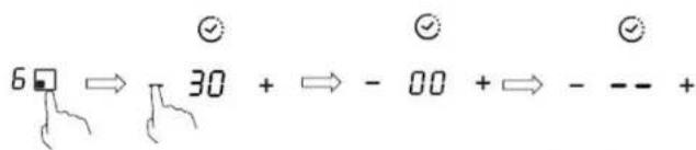
Setting the timer to turn one cooking zone off
Using the Timer
You can use the timer in two different ways:
- You can use it as a minute minder. In this case, the timer will not be cooking zone off when the set time is up.
- You can set it to turn one cooking zone off after the set time is up.
- You can set the timer up to 99 minutes.
Using the Timer as a Minute Minder
If you are not selecting any cooking zone
- Make sure the cooktop is turned on.
Note: you can use the minute minder even if you're not selecting any zone. -
Touch "-" or "+" of the timer control, the minde will start flashing and "00" will show in the timer display.
-
Set theme by touching the "-" or "+" control
Hint: Touch the "-" or "+" control once to decrease or increase by 1 min. Hold the "-" or "+" control of the timer to decrease or increase by minutes.
- Cancel the time by touching the "-" of timer and scrolling down to "0".
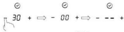
text_image
30 + ⇔ - 00 + ⇔ - -- +EN-19
Cooking zoes set for this feature will:


- Touching the heating zone selection control a) that you want to set the timer for. (e.g. zone
- Touch timer control, The minder indicator - 00 will start flashing and "00" will show in the timer display.
- Set theme by touching the "-" or "+" control.
Picking: Touch the "-" or "+" control once will decrease or increase by 1. Touch and hold the "-" or "+" control, the timer will decrease or by 10 minutes.
If the setgi time exceeds 99 minutes, th will automatically return to 0 minute.

- When the time is set, it will begin to coun - 36 + e. immediately. The display will show the remaini 10 time and ttemer indicator flash for 5 seconds.
NOTE: The die dot next to power level indicator will illuminate indicating that zone is selected.

- To cancel the timer, touch the heating zone select and then touch the "-" of timer and scrolling down to "0", the timer and the "00" will show in the minute display, and then "--".
EN-20
text_image
6 → 30 + → - 00 + → - -- +- When cooking timer expires, the corresponding cooking zone will be automatically switch off a show "H".


Other cooking zone will keep operating if they are turned on pre
Setting the timer to turn more than one cooking off
- If use this function to more than one heating zone, the timer indicates the shortest time. (e.g. zone1# setting time of 3 minutes, zone 2# setting time of 6 n the timer indicator shows "3".)
NOTE: The flashing red dot next to power level indicator means the indicator is showing time of the heating zone.
If you want to check the set time of other heating zone, touch the zone selection control. The timer will indicate its set time.


(set to 6 minutes)


(set to 3 minutes)

- When cooking timer expires, the corresponding heat will be automatically switch off and show "H".

NOTE: If you want to change the time after the timer is set, you h from step 1
Care and Cleaning
| What? How? Important! | |
| Everyday soiling on glass (fingerprints, marks, stains left food or non-sugary spillovers on the glass)1. Switch the power to the cooktop off.by. Apply a cooktop cleaner while the glass is still warm zone may still be hot! Take extreme care.3. Rinse and wipe dry with clean cloth or paper towel4. Switch the power to the cooktop back on. | ·When the power to the cooktop is switched off, there will be no 'hot surface' indication but the cooking zones may still be hot! Take extreme care.·a Heavy-duty scourers, some nylon scourers and harsh/abrasive cleaning agents may scratch the glass. Always read the label to check if your cleaner or scourer is suitable.·Never leave cleaning residue on the cooktop: the glass may become stained. |
| Boilovers, melts, and hot sugary spills on the glassRemove these immediately with a fish slice, palette knife razor blade scraper suitable. Induction glass cooktops, but beware of hot cooking zonesurfaces:1. Switch the power to the cooktop off at the wall.2. Hold the blade or utensil 30° angle and scrape the soiling or spill to a cool of the cooktop.3. Clean the soiling or spill up with a dish cloth or papertowel.4. Follow steps 2 to 4 for 'Everyday soiling on glass' above. | ·Remove stains left by melts and use sugary food or spillovers as soon foras possible. If left to cool on the glass, they may be difficult to remove or even permanently damage the glass surface.·Cut hazard: when the safety cover is retracted, the blade in a scraper is retracted. Use with extreme care and always store safely and about of reach of children. |
| Spillovers on the touch controls1. Switch the power to the cooktop off.2. Soak up the spill3. Wipe the touch control are liquid on them. Make sure you wipe with a clean damp sponge cloth.4. Wipe the area completely dry with a paper towel.5. Switch the power to the cooktop back on. | ·The cooktop may beep and turn itself off, and the touch controls may not function while there is liquid on them. Make sure you wipe the touch control area dry before turning the cooktop back on. |
Hints and Tips
| Problem Possible causes What to do | ||
| The induction hob cannot be turned on. | No power. Make sure the induction hob is connected to the power supply and that it is switched on. Check whether there is a power outage in your home or area. If you've checked everything and the problem persists, call a qualified technician. | |
| The touch controls are unresponsive. | The controls are locked. Unlock the controls. See section 'Using your induction cooktop' for instructions. | |
| The touch controls are difficult to operate. | There may be a slight film water over the controls or your dry and use the ball of your finger may be using the tip of your finger when touching the controls. | |
| The glass is being scratched. | Rough-edged cookware.Unsuitable, abrasive scourer orSee 'Care and cleaning'. | |
| Some pans make cracking or clicking noises. | This may be caused by the construction of your cookware (layers of different metals vibrating differently). | |
| The induction hob makes a low humming noise when used on a high heat setting. | This is caused by the technolngf induction cooking. This is normal, but the noise should quieten down or disappear completely when you decrease the heat setting. | |
| Fan noise coming from the induction hob. | A cooling fan built into your induction hob has come on prevent the electronics from overheating. It may continue run even after you've turned induction hob off. | |
| Pans do not become hot and appears in display. | The induction hob cannot detect the pan because it is suitable for induction cooking.The induction hob cannot detect the pan because it is too smallbe matches the size of the cooking for the cooking zone or not properly centred on it. | |
| The induction hob of cooking zone has turned itself off unexpectedly, a tone sounds and an error code is displayed (typically alternating with one or two digits in the cooking timer display). | Technical fault. Please note | down the error letters and numbers, switch the power to the induction hob off at the wall, and contact a qualified technician. |
Failure Display and Inspection
If an abnormality comes up, the induction hob will enter the protective automatically and display corresponding protective codes:
| Problem Possible causes What to do | |
| F3/F4 Temperature sensor of the induction coil failure | Please contact the supplier. |
| F9/FA Temperature sensor of the IGBT failure. | Please contact the supplier. |
| E1/E2 Abnormal supply voltage | Please inspect whether power supply is normal.Power on after the power supply is normal. |
| E3 High temperature of the induction coil temperature sensor | Please contact the supplier. |
| E5 High temperature of the IGBT temperature sensor | Please restart after the hob cools down. |
The above are the judgment and inspection of common failures. Please do not disassemble the unit by yourself to avoid any dangers and to the induction hob.
Technical Specification
| Cooking Hob | CIS633SCTT/1 CIS642SCTT/1 | |
| Cooking Zones | 3 Zones 4 Zones | |
| Supply Voltage | 220-240V~, 50-60Hz | 220-240V~, 50-60Hz |
| Installed Electric Power | 2.5kw:2250-2750W or 3.0 kw:2700-3300W or 4.5kw:4050-4950W or 5.5kw:4950-6050W or 6.9kw:5500-6900W | 2.5kw:2250-2750W or 8.0 kw:2700-3300W or 4.5kw:4050-4950W or 6.5kw:5850-7150W or 7.4kw:6600-7400W |
| Product Size L×W×H(mm) | 590X520X60 | 590X520X60 |
| Building-in Dimensions A×B (mm) | 560X490 560X490 | |
Weight and Dimensions are approximate. Because we continually strive to improve our products we may change specifications and designs without prior notice.
Installation
Selection of installation equipment
Cut out the work surface according to the sizes shown in the drawing.
For the purpose of installation and use, a minimum of 5 cm space shall be preserved around the hole.
Be sure the thickness of the work surface is at least 30mm. Please select heat-resistant work surface material to avoid larger deformation caused by the heat radiation from the hotplate. As shown below:
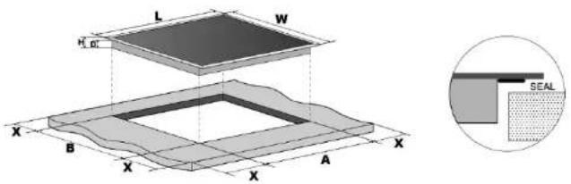
text_image
L W HCL X B X A X SEAL| L(mm) | W(mm) | H(mm) | D(mm) | A(mm) | B(mm) | X(mm) |
| 590 | 520 | 60 | 56 | 560.5 | 490.5 | 50 mini |
Under any circumstances, make sure the Induction cooker hob is well vent and the air inlet and outlet are not blocked. Ensure the Induction cooker good work state. As shown below
Note: The safety distance between the hotplate and the cupboard at the hotplate should be at leastm760
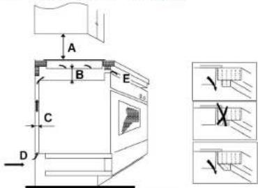
text_image
A B C D E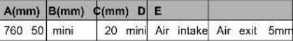 |
Before younstall the hob, make sure that
- the work surface is square and level, and no structural members interface space requirements
- the work surface is made of a heat-resistant material
- if the hob is installed above an oven, the oven has a built-in cooling
-
the installation will comply with all clearance requirements and applicable standards and regulations
-
a suitable isolating switch providing full disconnection from the mains supply is incorporated in the permanent wiring, mounted and positioned comply with the local wiring rules and regulations.
The isolating switch must be of an approved type and provide a 3 m contact separation in all poles (or in all active [phase] conductors if t wiring rules allow for this variation of the requirements) - the isolating switch will be easily accessible to the customer with the installed
- you consult local building authorities and by-laws if in doubt regarding installation
- you use heat-resistant and easy-to-clean finishes (such as ceramic tiles, wall surfaces surrounding the hob.
When you have installed the hob, make sure that
- the power supply cable is not accessible through cupboard doors or d
- there is adequate flow of fresh air from outside the cabinetry to the hob
- if the hob is installed above a drawer or cupboard space, a thermal barrier is installed below the base of the hob
- the isolating switch is easily accessible by the customer
Before locating the fixing brackets
The unit should be placed on a stable, smooth surface (use the packagi apply force onto the controls protruding from the hob.
Adjusting the bracket position
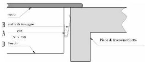
Fix the hob on the work surface by screw 4 brackets on the bottom (see picture) after installation.
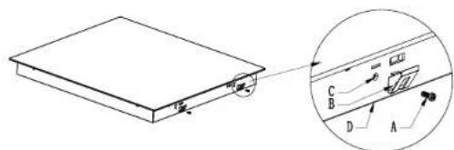
text_image
Technical diagram showing a rectangular component with labeled parts A, B, C, D and an inset view of a mechanical or electrical component.| A B C | D | ||
| Screw | Bracket Screw hole | Bottom case | |
EN-27
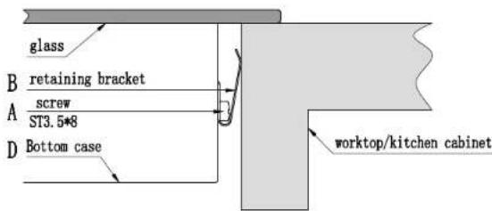
text_image
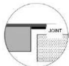
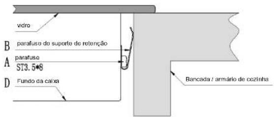
glass B retaining bracket A screw ST3.5*8 D Bottom case worktop/kitchen cabinetCautions
- The induction hotplate must be installed by qualified personnel or tecl We have professionals at your service. Please never conduct the opera yourself.
- The hob will not be installed directly above a dishwasher, fridge, free washing machine or clothes dryer, as the humidity may damage the electronics
- The induction hotplate shall be installed such that better heat radiatio ensured to enhance its reliability.
- The wall and induced heating zone above the table surface shall with
- To avoid any damage, the sandwich layer and adhesive must be resi heat.
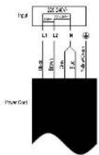
Connecting the hob to the mains power supply

This hob must be connected to the mains power supply only by a suitably quali. Before connecting the hob to the mains power supply, check that:
-
the domestic wiring system is suitable for the power drawn by the hob.
-
the voltage corresponds to the value given in the rating plate
-
the power supply cable sections can withstand the load specified on the rating. To connect the hob to the mains power supply, do not use adapters, reducers, devices, as they can cause overheating and fire.
The power supply cable must not touch any hot parts and must be positioned at temperature will not exceed 75^ C at any point.

Check with an electrician whether the domestic wiring system is suitable without all alterations must only be made by a qualified electrician.
The power supply should be connected in compliance with the relevant s or a single-pole circuit breaker. The method of connection is shown below
EN-28
- If the cabledamaged or to be replaced, the operation must be carried out by after-sale agent with dedicated tools to avoid any accidents.
- If the appliance is being connected directly to the mains an omnipolar circuit-breaker must be installed with a minimum opening of 3mm between contacts.
- The installer must ensure that the correct electrical connection has been m and that it is compliant with safety regulations.
• The cable must not be bent or compressed. - The cable must be checked regularly and replaced by authorised technicians only.
This appliance is labelled in accordance with European Directive 201, regarding electric and electronic appliances (WEEE). The WEEE contains polluting substances (that can have a negative effect on the environmental base elements (that can be reused). It is important that the WEEE specific treatments to correctly remove and dispose of the pollutant recover all the materials. Individuals can play an important role in that the WEEE do not become an environmental problem; it is also follow a few basic rules:
-the WEEE should not be treated as domestic waste; -the WEEE should be taken to dedicated collection areas managed by the town council or registered company. In many countries, domestic collections may be available for large WEEEs. When you buy a new appliance, the old one can be returned to the vendor who must accept it free of a one-off, as long as the appliance is of an equivalent type and has the same functions purchased appliance.
| Product Information for Domestic Electric Hobs Compliant to Commission Regulation 66/2014 | ||||||
| Position | Symbol Value | Value Unit | ||||
| Model Identification | CIS633SCTT/1 | CIS642SCTT/1 | ||||
| Type of hob: Electric Hob Electric Hob | ||||||
| Number of cooking zones and/or areas | zones 3 | 4 | ||||
| areas | ||||||
| the Heating technology (induction cooking zones and cooking areas, radiant cooking zones solid plates) | Induction cooking zones | X | X | |||
| Induction cooking cooking areas | ||||||
| radiant cooking zones | ||||||
| solid plates | ||||||
| For circular cooking zones areas: diameter of useful surface area per electric heated cooking zone, rounded to the nearest 5mmarge as as the | Rear left | ∅ | 18,0 | 18,0 | cm | |
| Rear central | ∅ | - | - | cm | ||
| Rear right | ∅ | - | 18,0 | cm | ||
| Central left | ∅ | - | - | cm | ||
| Central center | ∅ | - | - | cm | ||
| Central right | ∅ | 28,0 | - | cm | ||
| Front left | ∅ | 18,0 | 18,0 | cm | ||
| Front central | ∅ | - | - | cm | ||
| Front right | ∅ | - | 18,0 | cm | ||
| For non-circular cooking zones areas: length and width of Litter radius surface area per electric heated cooking zone or area, rounded the nearest 5mm | Rear left | LW | - | - | cm | |
| Rear central | LW | - | - | cm | ||
| Central left | LW | - | - | cm | ||
| Central central | L W | - | - | cm | ||
| Central right | L W | - - cm | ||||
| Front left | L W | - - cm | ||||
| Front central | L W | - - cm | ||||
| Front right | L W | - - cm | ||||
| Energy consumption for cook zone or area calculated per | Rear left | ECElectric cooking | 193,5 193,5 Wh/kg | |||
| Rear central | ECElectric cooking | - - Wh/kg | ||||
| Rear right | ECElectric cooking | - 1972 Wh/kg | ||||
| Central left | ECElectric cooking | - - Wh/kg | ||||
| ng Central kcentral | ECElectric cooking | - - Wh/kg | ||||
| Central right | ECElectric cooking | 190,9 - Wh/kg | ||||
| Front left | ECElectric cooking | 192,3 192,3 Wh/kg | ||||
| Front central | ECElectric cooking | - - Wh/kg | ||||
| Front right | ECElectric cooking | - 1956 Wh/kg | ||||
| Energy consumption for the calculated per kg | hob | ECElectric hob | 192,2 194,7 Wh/kg | |||
| Standard applied : EN 60350-2 Household electric cooking appliances - Part 2: Homeasuring performance | ||||||
| Suggestions for Energy Saving:To obtain the best efficiency of your hob, please place the pan in the centreUsing a lid will reduce cooking times and save energy by retaining the heat.Minimise the amount of liquid or fat to reduce cooking times.Start cooking on a high setting and reduce the setting when the food has heUse pans whose diameter is as large as the graphic of the zone selected. | ||||||
natural_image
Simple line drawing of a steaming appliance with heat dissipation, no text or symbols presentIT-9
text_image
Diagram showing correct and incorrect hand positions with checkmark and cross symbolsnatural_image
Four identical cooking pots with crossed-out X marks, no text or symbols presenttext_image
P → b → 9 □ Oppure P → - + → 3 □text_image
11□ 11□ → 6□ 6□Blocco dei comandi
text_image
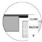
L W H X B X A X GUAR NICKIN E| W (mm) | H (mm) | D (mm) | A (mm) | B (mm) | X (mm) | |
| 590 | 520 | 60 | 56 | 560_+1 | 490_+3 | minimo50 |
text_image
Technical diagram showing a rectangular object with a curved arrow and a magnified inset of a mechanical component labeled A, B, C, D.| A B C D | |||
| Vite | Staffa | Foro per vite | Fondo |
natural_image
Simple line drawing of a steaming appliance with steam rising from its side (no text or symbols)FR-9
casserole en fer
text_image
Diagram showing two hand-drawn symbols: a checkmark and a cross, likely indicating correct or incorrect conditions.natural_image
Four identical illustrations of cooking pots with crossed X marks, no text or symbols presentchemical
Hand-drawn chemical reaction diagram showing electron transfer between two products with charge statesRemarque :
text_image
11□ 11□ → 6□ 6□text_image
L W H X B X A X Joint| L (mm) | W (mm) | H (mm) | D (mm) | A (mm) | B (mm) | X (mm) |
| 590 520 | 60 | 56 | 560 _+3 490 | _+3 50 | min |
text_image
A B C D E √ X √| A(mm) | B (mm) | C (mm) | D | E |
| 760 | 50 min. | 20 min. | Entrée d'air | Sortie de l'air 5 mm |
natural_image
Diagram of a coal stove with steam rising from its chimney, supported by two control panels (no text or symbols)ES-9
olla de hierro
text_image
Diagram showing two hand-drawn symbols: a checkmark and a cross, likely indicating correct or incorrect conditions.natural_image
Four identical cooking pots with crossed X marks, no text or symbols presenttext_image
Hand-drawn diagram showing a cooking step with a pot and a hand pointing to it, accompanied by a timer and square icon.text_image
P → b → 9 a P → - + → 3text_image
L W H 6° X B X A X JUNTA| L(mm) | W(mm) | H(mm) | D(mm) | A(mm) | B(mm) | X(mm) |
| 590 520 | 60 | 56 | 560 _+5 490 | _-5 50 | mín |
text_image
Technical diagram showing a rectangular plate with a circular component and an inset magnified view of a mechanical component labeled A, B, C, D.natural_image
Simple line drawing of a steaming appliance with heat dissipation, no text or symbols presenttext_image
Diagram showing two hand gesture options: checkmark and cross, likely indicating correct or incorrect actions.natural_image
Four identical cooking pots with crossed X marks, no text or symbols presentnatural_image
Simple line drawing of a cooking pot, a lid, and a hand holding a small object (no text or symbols)text_image
L W H X B X X A X| (MM) | W (MM) | H (MM) | D (MM) | A (MM) | B (MM) | X (MM) |
| 590 | 520 | 60 | 56 | 560, | 490, | мин. 50 |
text_image
Technical diagram showing a rectangular component with labeled parts A, B, C, D and an inset view of a device with labeled components.natural_image
Diagram of a steam heating machine with cooling unit and control panel (no text or symbols)Panela em ferro
Circuito magnético
text_image
Diagram showing two hand-drawn symbols: a checkmark and a cross, likely indicating correct or incorrect conditions.Seleccionar as panelas corretas

natural_image
Four identical cooking pots with crossed-out X marks, no text or symbols presenttext_image
Ou P → - + 3□Restrições de uso
text_image
6 → 30 + → - 00 + → - - - +text_image
L W H 01 X B X A X VEDANTE| C (mm) | L (mm) | A (mm) | D (mm) | A (mm) | B (mm) | X (mm) |
| 590 | 520 | 60 | 56 | 560_+5 | 490_+5 | 50 mini |
text_image
Technical diagram showing a rectangular component with labeled parts A, B, C, D and an inset view of a mechanical assembly with arrows and a numbered section.| D C B A | |||
| Aparafusar | Suporte | Furo do par | Fundo da caixa afuso |
natural_image
Simple line drawing of a steaming machine with heat dissipation, no text or symbols presentželezný hmec
magneticky okruh
sklokeramická deska
indukčni civka
indukované proudly
natural_image
Four identical illustrations of a cooking pot with crossed-out kitchen pan symbols (no text or labels)text_image
11□ 11□ → 6□ 6□text_image
L W H X B X A X TESNENI| D (mm) | (mm) | V | (mm) | H | (mm) | A | (mm) | B (mm) | X (mm) | |
| 590 | 520 | 60 | 560 | 56 | _+5 | 490 _-5 | 50 mini |
text_image
Technical diagram showing a rectangular component with labeled parts A, B, C, D and an inset view of a mechanical assembly with arrows and a magnified detail.natural_image
Simple line drawing of a stove with steam rising, no text or symbols presentżelazny garnek
obwód magnetyczny
text_image
Diagram showing two hand-drawn symbols: a checkmark and a cross, likely indicating correct or incorrect conditions.text_image
Diagram showing four cooking pots with crossed-out X symbols indicating absence or prohibitiontext_image
11□ 11□ 11□ → 6□ 6□text_image
Technical diagram showing a rectangular block with a circular component and an inset magnified view of a mechanical or electrical component labeled A, B, C, D.natural_image
Simple line drawing of a steaming machine with heat dissipation, no text or symbols presentželezný hrniec
magneticky obvod
sklokeramická doska
indukčná cievka
indukované prúdy
text_image
Hand-drawn checkmark and cross symbols on a line, indicating approval or rejection statusnatural_image
Four identical cooking pots with crossed-out X marks, no text or symbols presenttext_image
Alebo Alebotext_image
L W V X B X A X TESNENI| D(mm) | S(mm) | V(mm) | H(mm) | A(mm) | E(mm) | X(mm) | |
| 590 | 520 | 60 | 56 | 560_.s | 490_.s | ||
text_image
A B C D E X| A(mm) | B(mm) | C(mm) | D | E |
| 760 | 50 mini | 20 mini | Vstup vzduchu | Výstup vzduchu 5 mm |
text_image
Technical diagram showing a rectangular block with a curved arrow labeled '120' and an inset view of a mechanical component with labeled points A, B, C, D.text_image
Diagram showing a steaming machine with steam rising, connected to two cooler units labeled with Chinese characters.SL-11
železna posoda
ma
gnetni tokokrog
steklokeramična p
indukcijska
text_image
Four illustrated cooking pots with crossed-out kitchen pan symbols, indicating cooking resistance or resistance.text_image
D S V G X B X A X TESNILO| D (mm) | Š (mm) | V (mm) | G (mm) | A (mm) | B (mm) | X (mm) |
| 590 | 520 | 60 | 56 | 560_+5 | 490_-5 | najm. 50 |
natural_image
Simple line drawing of a steaming machine with cooling unit and heat exchanger (no text or symbols)Tava
magnetski strujni krug ploča od staklene keramike indukcijska zavojnica inducirane struje
Prije upotrebe vaše nove indukcijske ploče za kuhanje
- Pročitajte ovaj vodič, a posebnu pozornost obratite na odjeljak 'Sigurnosna upozorenja'.
- Uklonite sve zaštitne folije koje mogu biti postavljene na vašoj indukcijskoj ploči za kuhanje.
Upotreba upravljanja na dodir
text_image
Diagram showing two hand-drawn symbols: a checkmark and an X, likely indicating correct and incorrect conditions.natural_image
Four identical cooking pots with crossed X marks, no text or symbols presentUvijek podižite lonce s indukcijske ploče za kuhanje – nemojte ga gurati jer može ogrebati staklo.
Dimenzije lonca
Zone za kuhanje se određene granice automatski prilagođavaju promjeru lonca. Međutim, dno ove lonca mora imati najmanji promjer u skladu s odgovarajućom zonom kuhanja. Kako biste na najbolji način iskoristili svoju ploču za kuhanje, postavite lonac u središnji dio zone za kuhanje.
text_image
Diagram showing a hand pressing a hot pot on a surface with a timer indicating 0 seconds to press the flame.- Postavite razinu snage dodirivanjem „-“, „+“, ili povucite duž tipke za upravljanje „—“ ili samo dodirnite bilo koju točku tipke „—”.
text_image
- - + - + Ⅱi - - +lli
text_image
11□ 11□ → 6□ 6□- Za otkazivanje statusa stanke, dodirnite tipka STOP+GO, zatim će se zona za kuhanje vratiti na razinu snage koju ste ranije postavili.
text_image
11 11 11 11 → 6 6 6 6Blokiranje ploče za kuhanje
text_image
L W H B X A X X SEAL| D (mm) | (mm) | V (mm) | D (mm) | A (mm) | B (mm) | X (mm) |
| 590 | 520 | 60 | 56 | 560_1 | 490_16 | 50 mini |
natural_image
Diagram of a steaming machine with heat dissipation, showing airflow and control buttons (no text or symbols)change to the correct model name
change to the correct model name
text_image
Diagram illustrating the addition of a hand to a line with arrows, showing positive and negative values with directional arrows.change # 9, be correct
model name
text_image
→:2.5 3.0 ⑪15
ملحوظة
text_image
P → - 3□ + → 3□قيود استخدام
text_image
Group a Group b Group a Group bchange to the correct model name
المواصفات التقنية
text_image
L W H 0° X B X A X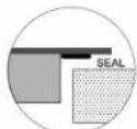
change to 56
natural_image
Technical diagram of a rectangular electronic component with a close-up inset showing labeled parts A, B, C, D (no text or symbols present)text_image
glass B retaining bracket A screw ST3.5*8 D Bottom case worktop/kitchen cabinetتحذیرات
change to the correct model name
natural_image
Simple line drawing of a steaming appliance with heat dissipation, no text or symbols presentметалевий посуд
магнітний контур
natural_image
Four identical cooking pots with crossed X marks, no text or symbols presenttext_image
Diagram showing three steps of a cooking process: pointing at a pot, demonstrating step 0, and using a mouse.chemical
Hand-drawn chemical reaction diagram showing electron movement and equilibrium between two moleculesUA16
Застереження:
text_image
P → b → 9 4u P → - + → 3text_image
L W H' H' X B X A X XUA27
| L (mm) | W (mm) | H (mm) | D (mm) | A (mm) | B (mm) | X (mm) |
| 590 | 520 | 60 | 56 | 560_-5 | 490_-5 | MH. 50 |
natural_image
Technical line drawing of a rectangular electronic device with a magnified inset showing internal components labeled A, B, C, D (no text or symbols beyond labels)natural_image
Simple line drawing of a steaming machine with cooling fans and heat exchangers (no text or symbols)gvozdeni lonac
magnetno strujno kolo keramička staklena ploča indukcioni kalem
indukovana struja
Pre upotrebe nove indukclone ploče
text_image
Diagram showing two hand-drawn symbols: a checkmark and a cross, likely indicating correct or incorrect conditions.Izbor odgovarajućeg posuđa

- Koristite samo posuđe sa osnovom pogodnom
natural_image
Four identical cooking pots with crossed-out handles, shown in sequence (no text or symbols)text_image
11□ 11□ → 6□ 6□text_image
L W H.0 X B X A X ZAPTIVKA| L (mm) | W (mm) | H (mm) | D (mm) | A (mm) | B (mm) | X (mm) |
| 590 | 520 | 60 | 56 | 560_-s | 490_-i | 50 mini |
text_image
Technical diagram showing a rectangular block with labeled points A, B, C, D and an angle marked at 10°, alongside an inset magnified view of a mechanical component.| DCBA | |||
| Vijak | Držač | Rupa za vijak | Donji deo |
text_image
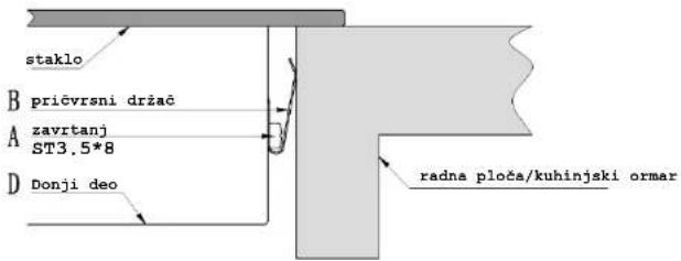
staklo B pričvrsni držač A zavrtanj ST3.5*8 D Donji deo radna ploča/kuhinjski ormarOprez
- Indukcionu ploču mora da ugradi kvalifikovano osoblje ili tehničari. Na raspolaganju vam stoje naši stručnjaci. Nikada ne obavljate ovu radnju samostalno.
- Ploča se ne ugrađuje direktno iznad mašine za pranje posuđa, frižidera, zamrzivača, mašine za pranje veša ili mašine za sušenje veša, jer vlaga može da ošteti elektroniku ploče
- Indukciona vruća ploča treba da se ugradi tako da se obezbedi bolje zračenje toplote radi povećanja pouzdanosti.
- Zid i zona indukovanog grejanja iznad površine stola moraju da izdrže toplotu.
- Da bi se izbegla oštećenja, slojevito umetanje sloja i lepak moraju biti otporni na toplotu.