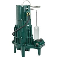
M53 - Water pump Zoeller - Free user manual and instructions
Find the device manual for free M53 Zoeller in PDF.
| Product type | Submersible sump pump |
| Brand | Zoeller |
| Model | M53 |
| Power supply | 115 V, 60 Hz, single-phase |
| Cable length | 8 m or 10 m depending on version |
| Discharge diameter | 1 1/2" NPT |
| Maximum water temperature | 54 °C (130 °F) |
| Control type | Built-in float switch |
| Maximum flow rate | Approximately 163 L/min at 1.5 m head |
| Maximum head | Approximately 5.9 m (19.25 ft) |
| Application | Clear water drainage, basement sump |
| Housing material | Cast iron or stainless steel (not specified) |
| Electrical protection | GFCI breaker required |
| Installation | Above ground level, in a basin |
| Maintenance | Check float, clean strainer, run once a month |
| Warranty | 3 years (according to warranty table) |
| Replacement parts available | Replacement pump (part number 007917 for M53 115V) |
Frequently Asked Questions - M53 Zoeller
User questions about M53 Zoeller
0 question about this device. Answer the ones you know or ask your own.
Ask a new question about this device
Download the instructions for your Water pump in PDF format for free! Find your manual M53 - Zoeller and take your electronic device back in hand. On this page are published all the documents necessary for the use of your device. M53 by Zoeller.
USER MANUAL M53 Zoeller
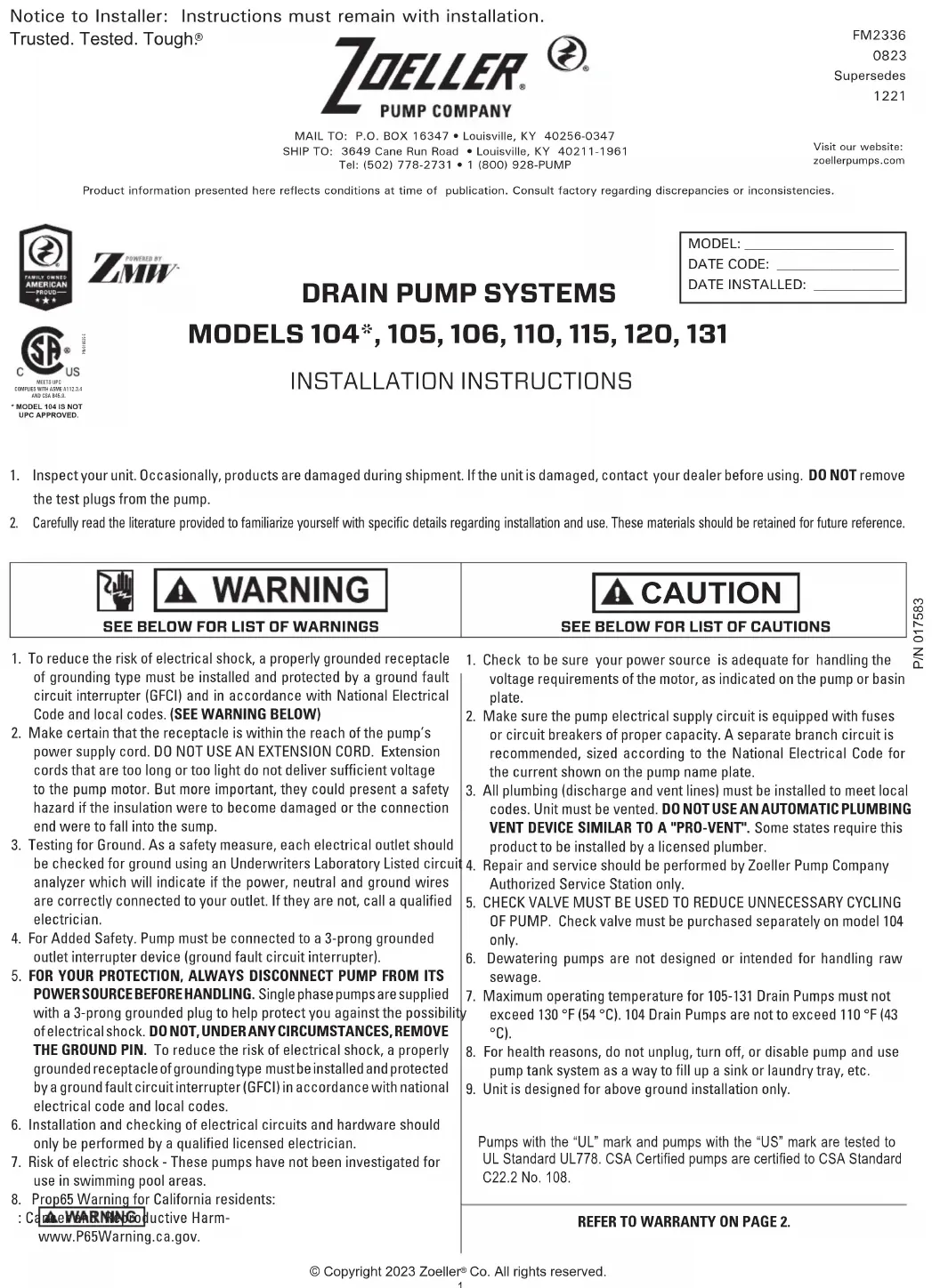
Product information presented here reflects conditions at time of publication. Consult factory regarding discrepancies or inconsistencies.


DRAIN PUMP SYSTEMS
MODEL:
DATE CODE:
DATE INSTALLED:

WHITS UPC COVPUES WITH ABOVE A112.8.4 END CSG B05.8
* MODEL 104 IS NOT UPC APPROVED.
MODELS 104\*, 105, 106, 110, 115, 120, 131
INSTALLATION INSTRUCTIONS
- Inspect your unit. Occasionally, products are damaged during shipment. If the unit is damaged, contact your dealer before using. DO NOT remove the test plugs from the pump.
- Carefully read the literature provided to familiarize yourself with specific details regarding installation and use. These materials should be retained for future reference.


SEE BELOW FOR LIST OF WARNINGS
- To reduce the risk of electrical shock, a properly grounded receptacle of grounding type must be installed and protected by a ground fault circuit interrupter (GFCI) and in accordance with National Electrical Code and local codes. (SEE WARNING BELOW)
- Make certain that the receptacle is within the reach of the pump's power supply cord. DO NOT USE AN EXTENSION CORD. Extension cords that are too long or too light do not deliver sufficient voltage to the pump motor. But more important, they could present a safety hazard if the insulation were to become damaged or the connection end were to fall into the sump.
- Testing for Ground. As a safety measure, each electrical outlet should be checked for ground using an Underwriters Laboratory Listed circuit analyzer which will indicate if the power, neutral and ground wires are correctly connected to your outlet. If they are not, call a qualified electrician.
- For Added Safety. Pump must be connected to a 3-prong grounded outlet interrupter device (ground fault circuit interrupter).
- FOR YOUR PROTECTION, ALWAYS DISCONNECT PUMP FROM ITS POWER SOURCE BEFORE HANDLING. Single phase pumps are supplied with a 3-prong grounded plug to help protect you against the possibility of electrical shock. DO NOT, UNDER ANY CIRCUMSTANCES, REMOVE THE GROUND PIN. To reduce the risk of electrical shock, a properly grounded receptacle of grounding type must be installed and protected by a ground fault circuit interrupter (GFCI) in accordance with national electrical code and local codes.
- Installation and checking of electrical circuits and hardware should only be performed by a qualified licensed electrician.
- Risk of electric shock - These pumps have not been investigated for use in swimming pool areas.
- Prop65 Warning for California residents:
: Came WARNING Reproductive Harm- www.P65Warning.ca.gov.

CAUTION
SEE BELOW FOR LIST OF CAUTIONS
- Check to be sure your power source is adequate for handling the voltage requirements of the motor, as indicated on the pump or basin plate.
- Make sure the pump electrical supply circuit is equipped with fuses or circuit breakers of proper capacity. A separate branch circuit is recommended, sized according to the National Electrical Code for the current shown on the pump name plate.
- All plumbing (discharge and vent lines) must be installed to meet local codes. Unit must be vented. DO NOT USE AN AUTOMATIC PLUMBING VENT DEVICE SIMILAR TO A "PRO-VENT". Some states require this product to be installed by a licensed plumber.
- Repair and service should be performed by Zoeller Pump Company Authorized Service Station only.
- CHECK VALVE MUST BE USED TO REDUCE UNNECESSARY CYCLING OF PUMP. Check valve must be purchased separately on model 104 only.
- Dewatering pumps are not designed or intended for handling raw sewage.
- Maximum operating temperature for 105-131 Drain Pumps must not exceed 130 °F (54 °C). 104 Drain Pumps are not to exceed 110 °F (43 °C).
- For health reasons, do not unplug, turn off, or disable pump and use pump tank system as a way to fill up a sink or laundry tray, etc.
- Unit is designed for above ground installation only.
Pumps with the "UL" mark and pumps with the "US" mark are tested to UL Standard UL778. CSA Certified pumps are certified to CSA Standard C22.2 No. 108.
REFER TO WARRANTY ON PAGE 2.
Limited Warranty
Manufacturer warrants, to the purchaser and subsequent owner during the warranty period, every new product to be free from defects in material and workmanship under normal use and service, when properly used and maintained, for THE PERIOD MENTIONED IN THE CHART BELOW FOR THE SPECIFIC MODEL PURCHASED, from the date of purchase. Proof of purchase is required. Parts that fail within the warranty period, that inspections determine to be defective in material or workmanship, will be repaired, replaced or remanufactured at Manufacturer's option, provided however, that by so doing we will not be obligated to replace an entire assembly, the entire mechanism or the complete unit. No allowance will be made for shipping charges, damages, labor or other charges that may occur due to product failure, repair or replacement. This warranty does not apply to and there shall be no warranty for any material or product that has been disassembled without prior approval of Manufacturer, subjected to misuse, misapplication, neglect, alteration, accident or act of nature; that has not been installed, operated or maintained in accordance with Manufacturer's installation instructions; that has been exposed to outside substances including but not limited to the following: sand, gravel, cement, mud, tar, hydrocarbons, hydrocarbon derivatives (oil, gasoline, solvents, etc.), or other abrasive or corrosive substances,
wash towels or feminine sanitary products, etc. in all pumping applications. The warranty set out in the paragraph above is in lieu of all other warranties expressed or implied; and we do not authorize any representative or other person to assume for us any other liability in connection with our products. Contact Manufacturer at, 3649 Cane Run Road, Louisville, Kentucky 40211, Attention: Customer Service Department to obtain any needed repair or replacement of part(s) or additional information pertaining to our warranty.
MANUFACTURER EXPRESSLY DISCLAIMS LIABILITY FOR SPECIAL, CONSEQUENTIAL OR INCIDENTAL DAMAGES OR BREACH OF EXPRESSED OR IMPLIED WARRANTY; AND ANY IMPLIED WARRANTY OF FITNESS FOR A PARTICULAR PURPOSE AND OF MERCHANTABILITY SHALL BE LIMITED TO THE DURATION OF THE EXPRESSED WARRANTY.
Some states do not allow limitations on the duration of an implied warranty, so the above limitation may not apply to you. Some states do not allow the exclusion or limitation of incidental or consequential damages, so the above limitation or exclusion may not apply to you. This warranty gives you specific legal rights and you may also have other rights which vary from state to state.
| Drain Pump Model | 104 105 106 110 115 120 131 | ||||||
| Pump Model | M72 | M53 | M63 | M55 | M57 | M59 | M98 |
| Warranty | 2 year | 3 year | 5 year | 1 year | 3 year | 1 year | 3 year |
In instances where property damages are incurred as a result of an alleged product failure, the property owner must retain possession of the product for investigation purpose.
Service Checklist

▲ WARNING ELECTRICAL PRECAUTIONS- Before servicing a pump, always shut off the main power breaker and then unplug the pump - making sure you are not standing in water and wearing insulated protective sole shoes. Under flooded conditions, contact your local electric company or a qualified licensed electrician for disconnecting electrical service prior to pump removal.
▲ WARNING Submersible pumps can become pressurized under normal operating conditions — allow 2-1/2 hours after disconnecting before attempting service.
| CONDITION | COMMON CAUSES |
| A. Pump will not start or run. | Check fuse, low voltage, overload open, open or incorrect wiring, open switch, impeller or seal bound mechanically, defective capacitor or relay when used, motor or wiring shorted. Float assembly held down. Switch defective, damaged, or out of adjustment. |
| B. Motor overheats and trips overload or blows fuse. | Incorrect voltage, negative head (discharge open lower than normal) impeller or seal bound mechanically, defective capacitor or relay, motor shorted. |
| C. Pump starts and stops too often. | Float too tight on rod, check valve stuck, or none installed in long distance line, overload open, switch defective. |
| D. Pump will not shut off. | Debris under float assembly, float or float rod bound by basin sides or other, switch defective, damaged or out of adjustment. |
| E. Pump operates but delivers little or no water. | Check strainer housing, discharge pipe, or if check valve is used, the vent hole must be clear. Discharge head exceeds pump capacity. Low or incorrect voltage. Incorrect motor rotation. Capacitor defective. Incoming water containing air or causing air to enter pumping chamber. |
| F. Drop in head and/or capacity after a period of use. | Increased pipe friction, clogged line or check valve. Abrasive material and adverse chemicals could possibly deteriorate impeller and pump housing. Check line. Remove base and inspect. |
| G. If tank or fittings leak. | Carefully tighten pipe joints (use pipe dope) and screws. Check gasket location, tighten lid evenly. Do not over tighten fittings or screws. |
If the above checklist does not uncover the problem, consult the factory. do you attempt to service or otherwise disassemble pump. Service must be performed by Zoeller authorized Service and warranty centers. Go to www.zoellerpump.com to find the authorized service center in your area.
Ten Helpful Hints For Easy Installation
- Read all instructions before beginning installation.
- Be certain that basin is on a firm level surface.
- Do not use an automatic plumbing vent device.
- Do not over-torque lid attachment screws.
- Always use a check valve on the discharge line.
-
Test operation of pump per STEP 6.
-
Always provide some means to disconnect basin from plumbing for maintenance purposes.
- Run unit at least once a month to verify proper operation.
- The model number and date code can be found on the lid warning label.
- Plug pump into a properly grounded GFCI receptacle.
Do's And Don't's For Installing A Unit
- DO read all installation material included with the pump.
- DO inspect unit for any visible damage caused by shipping. Contact dealer if unit appears to be damaged.
- DO clean all debris from the basin and pump.
-
DO always disconnect pump from power source before handling. DO always connect to a separately protected and properly grounded ground fault protected circuit. DO NOT ever cut, splice or damage power cord. DO NOT carry or lift pump by its power cord. DO NOT use an extension cord.
-
DO NOT use a discharge pipe smaller than the pump discharge size.
- DO test pump immediately after installation to be sure that the system is working properly.
- DO review all applicable local and national codes and verify that the installation conforms to each of them.
- DO NOT install unit in the ground.
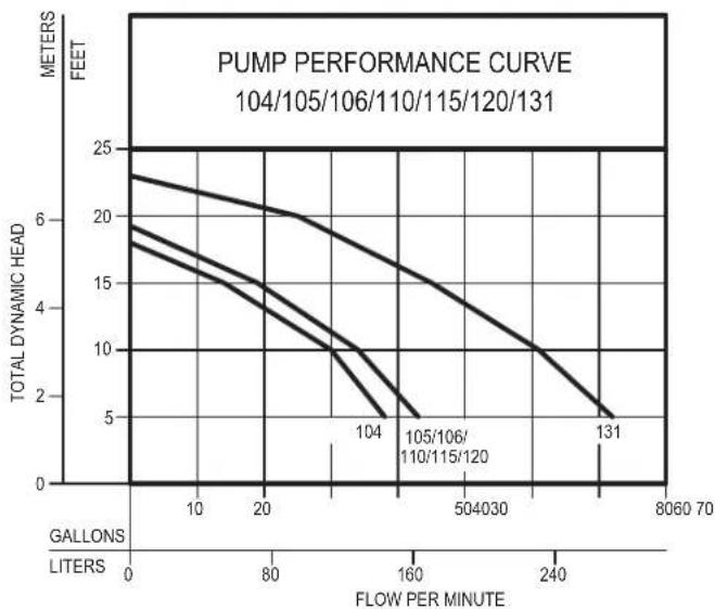
Performance Characteristics
line
| FLOW PER MINUTE | TOTAL DYNAMIC HEAD (meters) | | --------------- | --------------------------- | | 0 | 25 | | 80 | 20 | | 160 | 10 | | 240 | 5 | | 320 | 2 | | 400 | 1 | | 480 | 0.5 | | 560 | 0.2 | | 640 | 0.1 | | 720 | 0.05 || MODELS | 104 | 105/106110/115/120 | 131 | ||||
| Feet | Meters | Gal. | Liters Gal. | Liters Gal. | Liters | ||
| 5 1.5 | 38 | 144 | 43 | 163 | 72 | 273 | |
| 10 3.0 | 30 | 114 | 34 | 129 | 61 | 231 | |
| 15 4.6 | 14 | 53 | 19 | 72 | 45 | 170 | |
| 20 6.1 | -- | -- | -- | -- | 25 | 95 | |
| Shut-off Head: | 18 ft. (5.5m) | 19.25 ft. (5.9m) | 23 ft. (7.0m) | ||||
009898
STEP 1 determine Installation Configuration
NOTE: The basin is designed to be installed directly under the sink (Internal Trap) or on the side (Standard).

IMPORTANT!
Check local and state codes before using the internal trap option.
1.1) Figure 1.1A and 1.1B are typical configurations for installation of the drain systems. The actual configuration will vary depending on your cabinet and sink configuration.
NOTE: If installing the internal trap, record the "x" dimension, it will be required in Step 4.
INTERNAL TRAP COMPONENTS SUPPLIED BY OTHERS.!
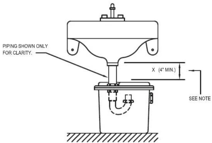
Figure 1.1A INTERNAL TRAP
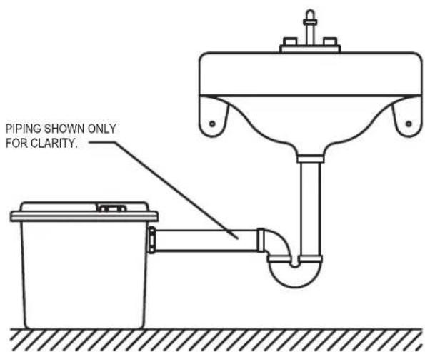
Figure 1.1B STANDARD (EXTERNAL TRAP)
SK2001
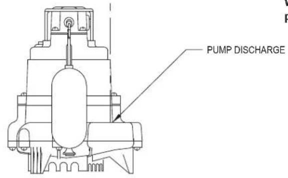
STEP 2 install the Discharge Pipe onto the Pump (All Models)
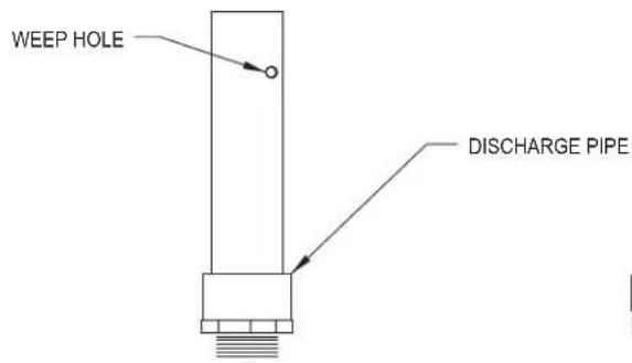
IMPORTANT! BE SURE THAT WEEPHOLE IS NOT DIRECTED TOWARD THE FLOAT!
Water stream will be visible from this hole during pump run periods.
SK2002
3.1) Install the gasket into the "gasket seat" at the top of the basin, refer to Figure 3.1 for details.
Figure 2.1
STEP 3 installation of the Gasket
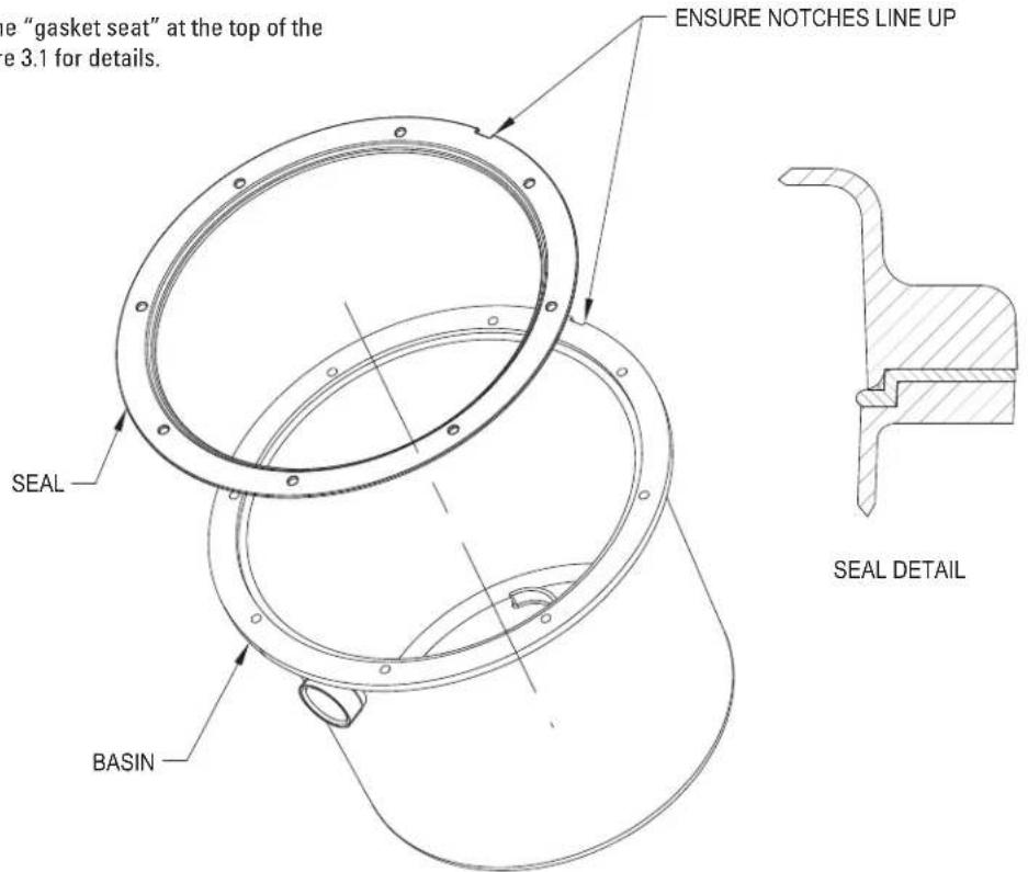
Figure 3.1
SK2972
STEP 4 Internal Trap Installation Only
4.1) Cut the tailpipe to the dimension determined in Figure 4.1.
4.2) Install the sink drain components to the lid as shown in Figure 4.2.
4.3) Orient the lid assembly as shown in Figure 4.3 and secure the trap components.
(HAND TIGHTEN the assembly to the lid at this time. Adjustment will be required in Step 5.)
Note: To ensure a proper water seal, the extension must be installed as shown in the "trap detail".
INTERNAL TRAP COMPONENTS SUPPLIED BY OTHERS.
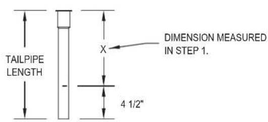
Figure 4.1
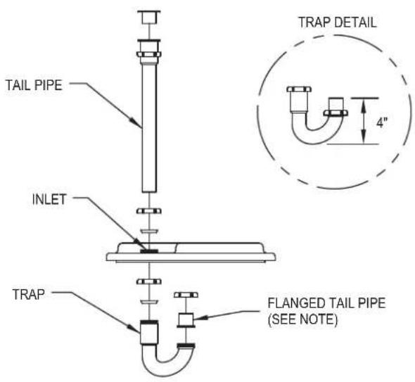
Figure 4.2
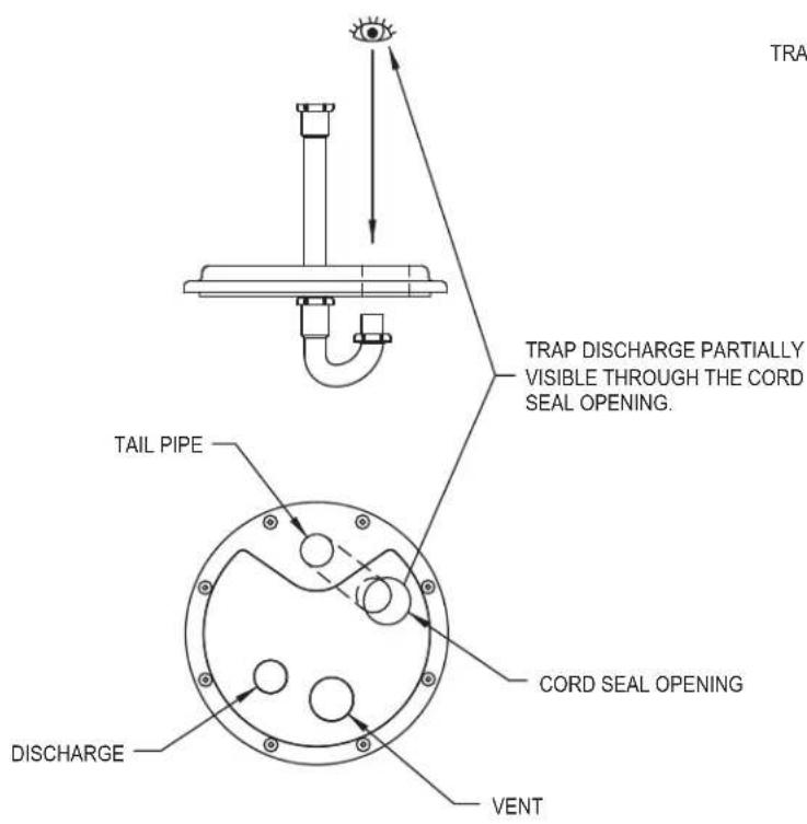
Figure 4.3
SK2004
STEP 5 final Assembly
NOTE: External plumbing configuration will vary depending on the location of basin, location of main stack and available space.
5.1) Place the pump in the basin as shown in Figure 5.1.
NOTE: If installing the internal trap, rotate the tail pipe to the orientation shown in Figure 5.1.
5.2) Install the lid components as shown in Figure 5.2.
NOTE: Pull excess cordage through the opening and install the cord seal as shown in Figure 5.3A. Insure o-ring is in the cap before installation.
5.3) Place the basin assembly in its final position and complete plumbing. Secure all connections (shown in 5.3A or 5.3B).
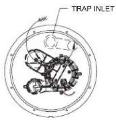
Figure 5.1
SK2005
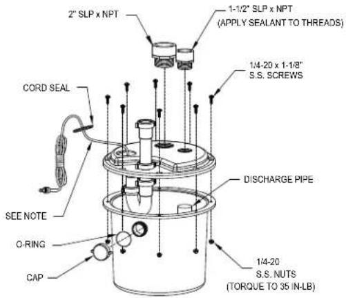
Figure 5.2
SK2007A
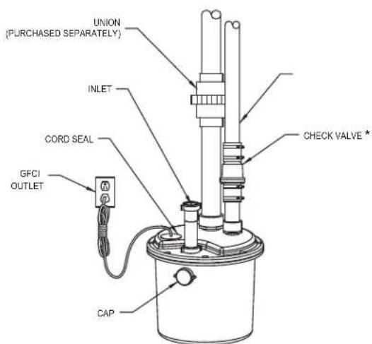
INTERNAL TRAP INSTALLATION STANDARD INSTALLATION
*CHECK VALVE MUST BE
PURCHASED SEPARATELY
FOR MODEL 104 & 132-0005.
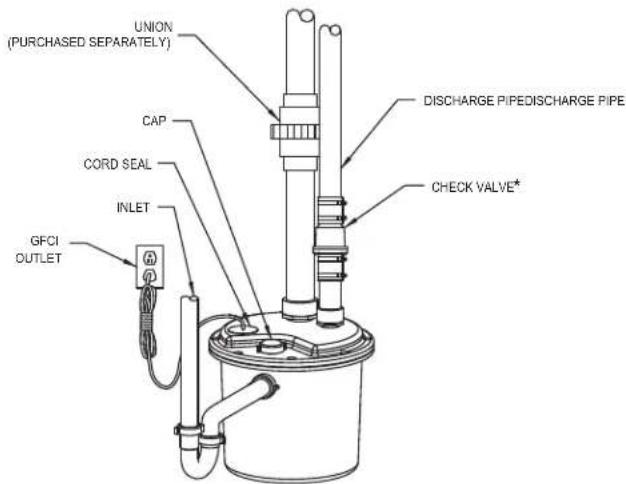
Figure 5.3B
SK2006
STEP 6 Initial Testing of Drain Basin System
6.1) Plug the cord into a properly grounded GFCI receptacle.
6.2) Fill tank with water.
6.3) Check all plumbing for leaks as the basin fills.
6.4) Verify that the pump starts and stops.
6.5.) Check the discharge line for leaks as the pump empties the basin.
6.6.) Repeat steps 6.2 to 6.5 as necessary to insure proper operation.
6.7.) If problems persist, refer to the troubleshooting guide located on page 2 of this manual.
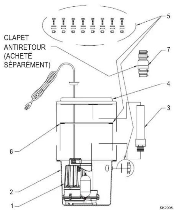
Illustrated Parts Breakdown
| MODELS | 105-D 106-A 110-D 115-D 120-D 131-C | 104-D | |||||||
| ITEM | DESCRIPTION QTY | 08/00 thru Current | 04/20 thru Current | 08/00 thru Current | 08/00 thru Current | 08/00 thru Current | 08/00 thru Current | 08/00 thru Current | |
| 1 | Replacement pump - M53/M55/M57/M59 (115V) | 1 | M53 007917 | N/A | M55 007918 | M57 007919 | M59 007920 | N/A N/A | |
| 1 | M53 (25' cord) 152119 | N/A N/A | N/A N/A | N/A N/A | |||||
| 1 | M53 (35' cord) 152120 | N/A N/A | N/A N/A | N/A N/A | |||||
| Replacement pump - M98 (115V) | 1 | N/A | N/A N/A | N/A N/A | M98 007921 | N/A | |||
| 1 | N/A | N/A N/A | N/A N/A | M98 (35' cord) 150116 | N/A | ||||
| Replacement pump - M72 (115V) | 1 | N/A | N/A | N/A | N/A | N/A | N/A | M72 72-0001 | |
| Replacement pump - M63 (115V) | 1 | N/A | M63 63-0009 | N/A N/A | N/A | N/A N/A | |||
| 2 | Basin - Tank | 1 | 013017 | 013017 | 013017 | 013017 | 013017 | 013017 | 013017 |
| 3 | Discharge Pipe | 1 | 013732 | 013732 | 013732 | 013732 | 013732 | 014759 | 013732 |
| 4 | Basin - Cover | 1 | 013018 | 013018 | 013018 | 013018 | 013018 | 013018 | 013018 |
| 5 | Hardware Pack & Seal | 1 | 152611 | 152611 | 152611 | 152611 | 152611 | 152611 | 152611 |
| 6 | Seal | 1 | 152607 | 152607 | 152607 | 152607 | 152607 | 152607 | 152607 |
| 7 | Unicheck | 1 | 30-0181 | 30-0181 | 30-0181 | 30-0181 | 30-0181 | 30-0181 | 30-0181 |
Notes:
1. Hardware pack consists of (8) 1/4" - 20 x 1-1/4" long hex washer stainless steel machine screws, (8) #1/4" - 20 hex flange stainless steel hex nuts along with (1) pipe cap, (1) O-ring, and (1) basin seal.
MODEL 105/106/110/115/120/131
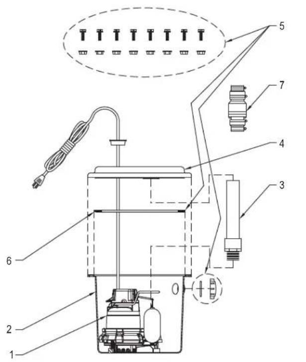
SK2008A
MODEL 104
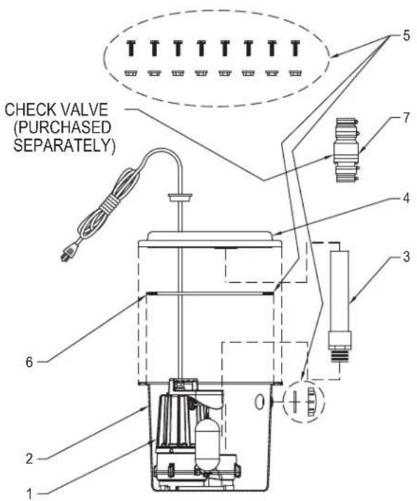
SK2008B
Trusted. Tested. Tough®
MODELO:
CÓDIGO DE FECHA:
FIGURA 1.1A TRAMPA INTERNA
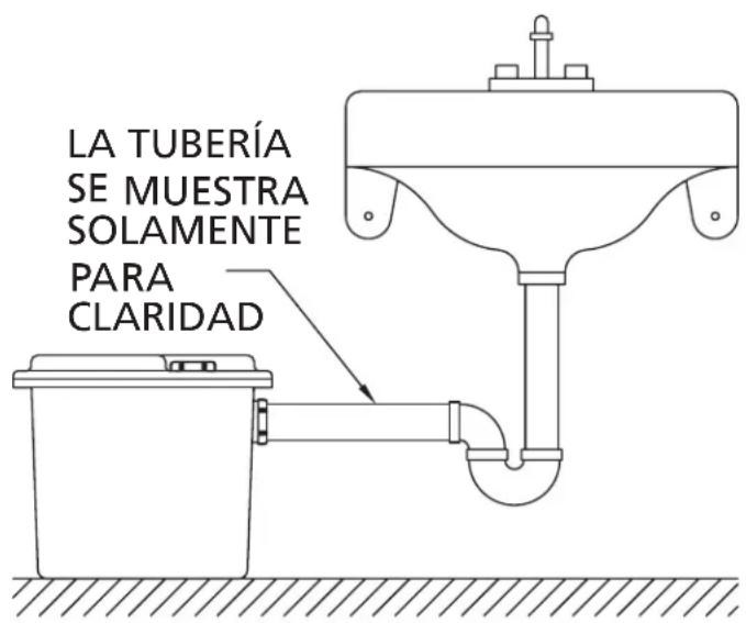
FIGURA 1.1B ESTÁNDAR (TRAMPA EXTERNA)
SK2001S
FIGURA 5.3A
FIGURA 5.3B
SK2006S
PASO 6
MODELO 1104
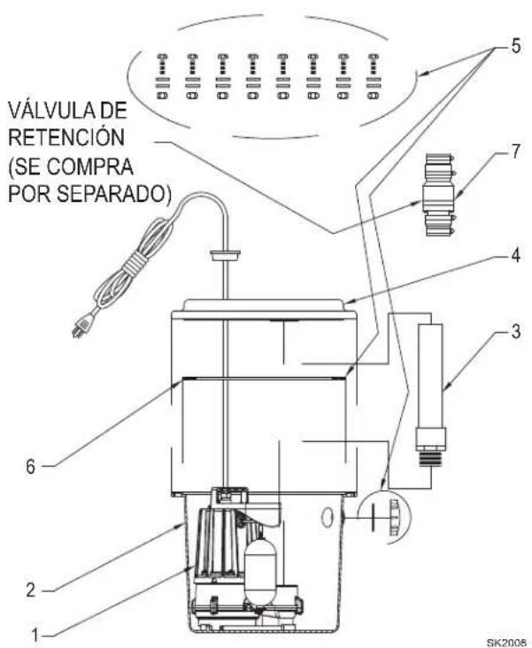
Figure 5.3A Figure 5.3B
SK2006F
MODÈLE 1104