
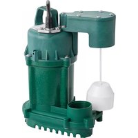
519-0005 - Water pump Zoeller - Free user manual and instructions
Find the device manual for free 519-0005 Zoeller in PDF.


| Product Type | Water Pump |
| Brand | Zoeller |
| Model | 519-0005 |
| Power Source | Electric, 120V AC |
| Motor Power | 0.5 HP |
| Flow Rate | 25 GPM (at 10 ft head) |
| Maximum Head | 25 ft |
| Discharge Size | 1-1/2 in. NPT |
| Dimensions (L x W x H) | 10 x 10 x 12 in. |
| Weight | 11 lbs |
| Construction | Cast Iron with Epoxy Coating |
| Thermal Protection | Automatic Reset |
| Cord Length | 10 ft |
| Maintenance | Inspect and clean strainer regularly |
| Safety Features | Overload protection, grounded plug |
| Spare Parts Availability | Authorized service centers and online retailers |
| Repairability | Replaceable motor and seal assembly |
| Typical Applications | Basement drainage, pool cover, and general dewatering |
Frequently Asked Questions - 519-0005 Zoeller
User questions about 519-0005 Zoeller
0 question about this device. Answer the ones you know or ask your own.
Ask a new question about this device
Download the instructions for your Water pump in PDF format for free! Find your manual 519-0005 - Zoeller and take your electronic device back in hand. On this page are published all the documents necessary for the use of your device. 519-0005 by Zoeller.
USER MANUAL 519-0005 Zoeller
NOTICE TO INSTALLER: Instructions must remain with installation.
Trusted. Tested. Tough.®
Product information presented here reflects conditions at time of publication. Consult factory regarding discrepancies or inconsistencies.

FM3130
0719
Supersedes
New
MAIL TO: P.O. BOX 16347 • Louisville, KY 40256-0347
SHIPTO: 3649 Cane Run Road • Louisville, KY 40211-1961
TEL: (502) 778-2731 • 1 (800) 928-PUMP • FAX: (502) 774-3624
Visit our web site:
zoeller.com
Register your
Zoeller Pump Company
Product on our website:
http://reg.zoellerpumps.com/
INSTALLATION INSTRUCTIONS
MODEL 519 and 522 Condensate Pumps
- Inspect all materials. Occasionally, products are damaged during shipment. If the unit is damaged, contact your dealer before using.
- Carefully read all the literature provided to familiarize yourself with specific details regarding installation and use before attempting the installation. These materials should be retained for future reference.

WARNING
SEE BELOW FOR LIST OF WARNINGS
- To help reduce the risk of electrical shock, a properly grounded receptacle or control box of grounding type must be installed and protected by a ground fault circuit interrupter (GFCI) in accordance with the National Electrical Code and applicable local codes. If pump is wired direct, a GFCI must be installed in the control box. (SEE WARNING BELOW)
- Make certain that the ground fault interrupter protected receptacle or control box is within reach of the pump's power supply cord. DO NOT USE AN EXTENSION CORD. Extension cords that are too long or too light do not deliver sufficient voltage to the pump motor. But more important, they could present a safety hazard if the insulation were to become damaged or the connection end were to fall into a damp or wet area.
-
Make sure the pump's electrical supply circuit is equipped with fuses or circuit breakers of proper capacity. A separate branch circuit, sized according to the National Electrical Code for the current shown on the pump name plate is recommended.
-
TESTING FOR GROUND. As a safety measure, each electrical outlet should be checked for ground using an Underwriters Laboratory Listed circuit analyzer which will indicate if the power, neutral and ground wires are correctly connected to your outlet. If they are not, call a qualified licensed electrician.
- Installation and checking of electrical circuits and hardware should only be performed by a qualified licensed electrician.
- FOR YOUR PROTECTION ALWAYS DISCONNECT PUMP FROM ITS POWER SOURCE BEFORE HANDLING.
- Prop65 Warning for California residents: Cancer and Reproductive Harm- www.P65Warnings.ca.gov.
CAUTION
SEE BELOW FOR LIST OF CAUTIONS
- Check to be sure your power source is adequate to handle the amperage requirements of the motor as indicated on the pump or unit I.D. tag.
- All plumbing (discharge and drain lines) must be installed to meet local codes.
- This pump has been evaluated for use with water only.
NOTE: Pumps with the "UL" mark and pumps with the "US" mark are tested to UL Standard UL778. CSA Certified pumps are certified to CSA Standard C22.2 No. 108.
REFER TO WARRANTY ON PAGE 2.
Limited Warranty
Zoeller Pump Company warrants, to the purchaser and subsequent owner during the warranty period, every new Zoeller Pump Company product to be free from defects in material and workmanship under normal use and service, when properly installed, used and maintained, for a period of two years from date of purchase. Proof of purchase is required. Parts that fail within the warranty period that inspections determine to be defective in material or workmanship, will be repaired, replaced or remanufactured at Zoeller Pump Company's option, provided however, that by so doing we will not be obligated to replace an entire assembly, the entire mechanism or the complete unit. No allowance will be made for shipping charges, damages, labor or other charges that may occur due to product failure, repair or replacement.
This warranty does not apply to any material that has been disassembled without prior approval of Zoeller Pump Company, subjected to misuse, misapplication, neglect, alteration, accident or act of God; that has not been installed, operated or maintained in accordance with Zoeller Pump Company installation instructions; that has been exposed to but not limited to the following: sand, gravel, cement, mud, tar, hydrocarbons or hydrocarbon derivatives (oil, gasoline, solvents, etc), wash towels or feminine sanitary products, etc. or other abrasive or corrosive substances. This warranty is in lieu of all other warranties expressed
or implied; and we do not authorize any representative or other person to assume for us any other liability in connection with our products.
Contact Zoeller Pump Company, 3649 Cane Run Road, Louisville, Kentucky 40211-1961, Attention: Customer Service Department to obtain any needed repair or replacement of part(s) or additional information pertaining to our warranty.
ZOELLER PUMP COMPANY EXPRESSLY DISCLAIMS LIABILITY FOR SPECIAL, CONSEQUENTIAL OR INCIDENTAL DAMAGES OR BREACH OF EXPRESSED OR IMPLIED WARRANTY; AND ANY IMPLIED WARRANTY OF FITNESS FOR A PARTICULAR PURPOSE AND OF MERCHANTABILITY SHALL BE LIMITED TO THE DURATION OF THE EXPRESSED WARRANTY.
Some states do not allow limitations on the duration of an implied warranty, so the above limitation may not apply to you. Some states do not allow the exclusion or limitation of incidental or consequential damages, so the above limitation or exclusion may not apply to you.
This warranty gives you specific legal rights and you may also have other rights which vary from state to state.
In instances where property damages are incurred as a result of an alleged product failure, the property owner must retain possession of the product for investigation purpose.
Ten Helpful Hints or Easy Installation
| 1. Read all instructions before beginning installation. | 6. Test operation of pump per STEP 5. |
| 2. Be sure the installation does not exceed a maximum of 15 feet of vertical lift. | 7. Do not overtighten check valve after cleaning. Refer to maintenance guidelines. |
| 3. Be sure the pump is level within 1/8" for the length of the condensate pump. | 8. Plug pump into a constant voltage source. Do not plug into a device that runs intermittently. |
| 4. Use soapy water when cleaning unit. Refer to maintenance guidelines. | 9. The model number and date code can be found on the pump I.D. label. |
| 5. For best results, drain and discharge lines should have a continuous downward slope. | 10. For best results, the highest point of the discharge line should be higher than 5' above floor. |
Do's and Do Nots or Installing Unit
| 1. DO read all installation material included with the pump. | 5. DO NOT use a discharge pipe smaller than the pump discharge size. |
| 2. DO inspect unit for any visible damage caused by shipping.Contact dealer if unit appears to be damaged. | 6. DO test pump immediately after installation to be sure that the system is working properly. |
| 3. DO clean all debris from the pump reservoir. | 7. DO review all applicable local and national codes and verify that the installation conforms to each of them. |
| 4. DO always disconnect pump from power source before handling. DO always connect to a separately protected and properly grounded ground fault protected circuit. DO NOT ever cut, splice or damage power cord. DO NOT carry or lift pump by its power cord. DO NOT use an extension cord with this condensate pump. | 8. Do not use Flexible tubing larger than 3/8". |
STEP 1ounting Location
1.1) Select a location for the pump that is below the evaporator drain and/or furnace drain.
1.2) The unit has two mounting brackets built into the deck so the pump can be attached to the wall or side of the appliance. Refer to Figure 1.2.
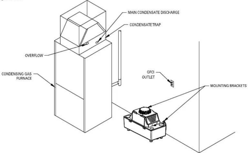
Figure 1.2
SK3177
STEP 2 Installation of Condensate Drain Lines
2.1) To prevent pipe blockage, modify the end of the pipe or tubing as shown in Figure 2.1.
2.2) Plumb, flexible tube or pipe, from the condensate drain and/or from the furnace drain to the inlet hole(s) on the pump. Refer to Figure 2.2.

Figure 2.2 Figure 2.1
Note: The drain line(s) should have a continuous downward slope to allow for gravity flow.
Note: Local codes may require the use of a condensate neutralizer when using this pump.
Note: Make sure the drain lines from the A.C. condenser are supported above the reservoir and no weight from the drain line is directed to the bottom of the reservoir.
STEP 3 Installation of Discharge Line
Note: Do not use flexible tubing larger than 3/8" ID. A hose clamp (not included) is recommended.
3.1) Extend the discharge pipe, from the barbed check valve, to the highest point possible. Refer to Figure 3.1
3.2) From this point, direct the discharge line to the location of the main drain, maintain a continuous downward slope.
Note: If a continuous downward slope is not possible, then make an inverted "U" at the highest point of the discharge line.
Note: Make sure the 3/8" ID tube is supported in a way it will not "Kink or Pinch off" blocking flow.

Figure 3.1
SK3179
STEP 4 Installation of Safety Switch
4.1) The pump safety switch should be used on 24V Class II control circuits only. The pump safety switch connections are available on the two wire leads extending from the pump. Wire into the 24 Volt thermostat circuit to shut off A/C systems should an overflow condition occur. The Safety Switch operates with or without power provided to the pump.

Figure 4.1
STEP 5 testing of Pump Operation
5.1) Testing of Pump (Main Switch)
1) With the discharge line in place, plug in the pump.
2) Pour water into the pump reservoir, through one of the inlets, until the pump activates to verify that the unit works.
5.2) Testing of Safety Switch (If applicable)
Note: Unplug the pump for this test.
1) Energize the appliance so that it runs.
2) Pour water into the reservoir as described in Section 5.1 item 2.
3) As water rises in the reservoir, the overflow Switch should activate, breaking the thermostat circuit to the appliance.
4) Plug the pump in and allow the pump to empty the tank. As the water level decreases, the appliance will reset.
Maintenance Guidelines
Cleaning of Reservoir:
1) Remove entire pump from wall, if mounted.
2) Disassemble reservoir from the deck by inserting a screwdriver in either side of the deck.
3) Clean reservoir as needed.
4) Reassemble reservoir to the deck.
Cleaning of Check Valve:
1) Remove discharge line from valve.
2) Remove check valve with 9/16" wrench.
3) Visually check for obstructions or damage.
4) Replace valve by hand tightening, then tighten 1/2 turn with a 9/16" wrench.
CAUTION
Do not overtighten.
| Trouble Shooting Guide | ||
| Condition Possible Cause Remedy | ||
| A. UNIT DOESN'T RUN. | Pump not plugged in. Plug in. | |
| Low voltage; blown fuse, open circuit. | Have a qualified electrician check fuse circuit. | |
| No condensate in reservoir. Be certain the appliance is generating condensate.Check drain line(s) and/or discharge line for blockage. | ||
| Motor or wiring shorted. Contact Factory. | ||
| Drain/Discharge line(s) blocked. Check drain line(s) and/or discharge line for blockage. | ||
| B. PUMP MAKES LOUD NOISES WHEN RUNNING. | Debris in reservoir. Refer to “Maintenance Guidelines” section for cleaning instructions. | |
| C. PUMP RUNS BUT DOES NOT PUMP LIQUID OUT. | Float bound. Refer to “Maintenance” section for cleaning instructions. | |
| Maximum discharge height exceeded. Measure from bottom of pump to highest point.Rework discharge if height is greater that 18'.Refer to STEP 3 for guidelines. | ||
| Discharge tube blocked. Check discharge line for blockage, remove debris. | ||
| Check Valve obstruction. Refer to “Maintenance” section for cleaning instructions. | ||
| Check Valve damaged. | Contact Factory. | |
| D. LIQUID DRAINS BACK INTO PUMP FROM DISCHARGE LINE. | Check Valve damaged. | Contact Factory. |
| Check Valve obstruction. Refer to “Maintenance” section for cleaning instructions. | ||
| Highest point of discharge line is less than 5'. | Check valve may allow some condensate to drain out of line into reservoir. This is normal. | |
| E LIQUID LEAKS FROM AROUND CHECK VALVE. | Check Valve is too tight or too loose. | Check valve should be hand tight, then tighten an additional 1/2 turn with a 9/16" wrench. |

WARNING
Before servicing a pump, always shut off the main
power breaker and then unplug the pump - making sure you are
not standing in water and are wearing insulated, protective-sole
shoes. Under flooded conditions, contact your local electric company
or a qualified licensed electrician for disconnecting electrical service
prior to pump removal.
If the above checklist does not solve the problem, consult Zoeller Technical Service Department 1-(800) 928-PUMP - Do not attempt to service or
otherwise disassemble pump.
NOTES
NOTES

MAILTO: P.O. BOX 16347 • Louisville, KY 40256-0347
SHIPTO: 3649 Cane Run Road • Louisville, KY 40211-1961
(502) 778-2731 • 1 (800) 928-PUMP • FAX (502) 774-3624
Trusted. Tested. Tough.®
Visit our web site:
zoeller.com
- NOTICE TO INSTALLER: Instructions must remain with installation.
- INSTALLATION INSTRUCTIONS
- MODEL 519 and 522 Condensate Pumps
- WARNING
- SEE BELOW FOR LIST OF WARNINGS
- CAUTION
- SEE BELOW FOR LIST OF CAUTIONS
- Limited Warranty
- STEP 1ounting Location
- STEP 2 Installation of Condensate Drain Lines
- STEP 3 Installation of Discharge Line
- STEP 4 Installation of Safety Switch
- STEP 5 testing of Pump Operation
- 5.1) Testing of Pump (Main Switch)
- 5.2) Testing of Safety Switch (If applicable)
- Maintenance Guidelines
- Cleaning of Reservoir:
- Cleaning of Check Valve:
- NOTES
Brand : Zoeller
Model : 519-0005
Category : Water pump