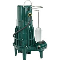
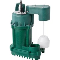
M161 - Water pump Zoeller - Free user manual and instructions
Find the device manual for free M161 Zoeller in PDF.


| Product Type | Submersible pump for wastewater/effluent |
| Brand | Zoeller |
| Model | M161 |
| Power Supply | 230 V, single phase, 60 Hz (WD) / 200-208 V, single phase, 60 Hz (WH) |
| Motor Power | 0.5 HP (estimated) |
| Maximum Flow Rate | 100 L/min (estimated) |
| Maximum Discharge Head | 8 m (estimated) |
| Discharge Diameter | 1 1/2 in (DN40) or 2 in (DN50) |
| Maximum Liquid Temperature | 54 °C (standard), 43 °C (series 70), 40 °C (series 73/75) |
| Solids Handling Capacity | Up to 19 mm (3/4 in) for certain models |
| Control Type | Automatic with float switch (WD/WH models) |
| Electrical Protection | Three-prong plug with grounding |
| Cable Length | Approximately 3 m (estimated) |
| Net Weight | 12 kg (estimated) |
| Dimensions (L x W x H) | 30 x 30 x 50 cm (estimated) |
| Warranty | 1 year (parts and labor) |
| Standards | UL 778, CSA C22.2 No. 108 |
| Maintenance | Regularly clean the 5 mm (3/16 in) vent hole under the check valve |
| Usage | Sump, dewatering, effluent (do not use for potable water) |
| Precautions | Do not use extension cord, always unplug before servicing |
Frequently Asked Questions - M161 Zoeller
User questions about M161 Zoeller
0 question about this device. Answer the ones you know or ask your own.
Ask a new question about this device
Download the instructions for your Water pump in PDF format for free! Find your manual M161 - Zoeller and take your electronic device back in hand. On this page are published all the documents necessary for the use of your device. M161 by Zoeller.
USER MANUAL M161 Zoeller
Notice to installing contractor: Instructions must remain with installation.
Trusted. Tested. Tough.®
DATE INSTALLED:
MODEL NUMBER:
ZOELLER® PUMP COMPANY

MAIL TO: P.O. BOX 16347 • Louisville, KY 40256-0347 SHIP TO: 3649 Cane Run Road • Louisville, KY 40211-1961 Tel: (502) 778-2731 • 1 (800) 928-PUMP
FM0447
Rev. A
0823
Supersedes
0220
Visit our website:
zoellerpumps.com
Product information presented here reflects conditions at time of publication. Consult factory regarding discrepancies or inconsistencies.


55, 57 pumps powered by Zoeller Motor Works motor
INSTALLATION INSTRUCTIONS
RECOMMENDED MODELS
Register your
Zoeller Pump Company
Product on our website: http://reg.zoellerpumps.com

Many Zoeller products contain registered trademarks for design and/or the color green: U.S. #4,849,524 / #5,024,907
| EFFLUENT*/SUMP/DEWATERING SE | WAGE |
| 55 / 59, 139 Series | |
| 140 / 4140, 145 / 4145, 160 / 4160 Series 270 / 4270 Series | |
| 180 / 4180, 191, 371, 372, 373 Series 280 / 4280, 290 / 4290 Series |
NOTICE: VENT HOLE FOR CHECK VALVE SEE #3 IN CAUTION SECTION BELOW AND #4 ON PAGE 3
P/N 006355
* Effluent systems should specify that pumps should not handle solids exceeding 3/4" (19 mm) in order to prevent large solids from entering leeching fields, mound systems, etc. (70 Series have 3/8" (9 mm) solids capability. 50, 140/4140, 371 and 372 Series have 1/2" (13 mm), 130 Series has 5/8" (16 mm), 145/4145, 160/4160, 180/4180 and 373 models have 3/4" [19 mm].) Where code permits, sewage pumps can be used for effluent systems. Non-automatic pumps with external-level controls are recommended for septic tank effluent applications.
PREINSTALLATION CHECKLIST - ALL INSTALLATIONS
- Inspect all materials. Occasionally, products are damaged during shipment. If the unit is damaged, contact your dealer before using. DO NOT remove the test plugs from the pump.
- Carefully read the literature provided to familiarize yourself with specific details regarding installation and use. These materials should be retained for future reference.


SEE BELOW FOR LIST OF WARNINGS
- To reduce the risk of electrical shock, a properly grounded receptacle or control box must be installed in accordance with the governing codes. Never remove ground pin from plug.
- Make certain that the ground fault interrupter protected receptacle or control box is within the reach of the pump's power supply cord. DO NOT USE AN EXTENSION CORD. Extension cords that are too long or too light do not deliver sufficient voltage to the pump motor, and they could present a safety hazard if the insulation were to become damaged or the connection end were to fall into a damp or wet area.
- Make sure the pump's electrical supply circuit is equipped with fuses or circuit breakers of proper capacity. A separate branch circuit is recommended, sized according to the local electrical codes for the current shown on the pump name plate.
- Testing for ground. As a safety measure, each electrical outlet should be checked for ground using a circuit analyzer which will indicate if the power, neutral and ground wires are correctly connected to your outlet. If they are not, call a qualified licensed electrician.
- FOR YOUR PROTECTION, ALWAYS DISCONNECT PUMP FROM ITS POWER SOURCE BEFORE HANDLING. If pump is wired direct, de-energize the circuit at the control box. Wear insulated protective shoes and do not stand in water. Pumps equipped with a 3-prong ground plug are designed to help protect against electrical shock. DO NOT, UNDER ANY CIRCUMSTANCES, REMOVE THE GROUND PIN.
- Installation and servicing of the pump, electrical circuits and hardware should only be performed by a qualified, licensed electrician.
- Risk of electrical shock. Do not remove power supply cord and strain relief or connect conduit directly to the pump. If the supply cable is damaged, it must be replaced by the Manufacturer or an Authorized Service and Warranty Center to avoid a hazard.
- Pump contains oil which becomes pressurized and hot when operating. Allow 2-1/2 hours after disconnecting before attempting service.
- Pump is not intended for potable water due to possible contamination by oil contained in the pump.
- Risk of electrical shock. These pumps have not been investigated for use in swimming pools and marine areas.
- Prop65 Warning for California residents: Cancer and Reproductive Harmwww.P65Warnings.ca.gov.

SEE BELOW FOR LIST OF CAUTIONS
- Check to be sure your power source is capable of handling the voltage requirements of the motor, as indicated on the pump name plate.
- The installation of variable level float switches is the responsibility of the installing party, and care should be taken that the tethered float switch will not hang up on the pump apparatus or pit peculiarities and is secured so that the pump will shut off. It is recommended to use rigid pipe and fittings and the pit be 18" (46 cm) or larger in diameter.
- Vent hole. It is necessary that all submersible sump, effluent, and sewage pumps capable of handling various sizes of solid waste be of the bottom intake design to reduce clogging and seal failures. If a check valve is incorporated in the installation, a 3/16" (5 mm) vent hole must be drilled in the discharge pipe below the check valve and pit cover to purge the unit of trapped air. Vent hole should be checked periodically for clogging. The vent hole on a High Head application may cause too much turbulence. If you choose not to drill a vent hole, be sure the pump case and impeller is covered with liquid before connecting the pipe to the check valve. NOTE: THE HOLE MUST BE BELOW THE BASIN COVER AND CLEANED PERIODICALLY. Water stream will be visible when pump is operating.
- Pump should be checked frequently for debris and/or build up which may interfere with the float "on" or "off" position. Repair and service should be performed by an Authorized Service and Warranty Center.
- Maximum operating temperature for standard model pumps must not exceed 130 °F (54 °C). Maximum operating temperatures for 70 series and model 211 must not exceed 110 °F (43 °C). Maximum operating temperatures for 73, 75, must not exceed 104 °F (40 °C).
- Do not operate a pump in an application where the Total Dynamic Head is less than the minimum Total Dynamic Head listed on the Pump Performance Curves.
- For health reasons, do not unplug, turn off, or disable pump and use pump tank system as a way to fill up a sink or laundry tray, etc.
- Pumps must be installed in accordance with the National Electrical Code and all applicable local codes and ordinances. Pumps are not to be installed in locations classified as hazardous in accordance with National Electric Code, ANSI, NFPA 70.
NOTE: Pumps with the "UL" mark and pumps with the "US" mark are tested to UL standard UL778. CSA certified pumps are certified to CSA standard C22.2 No. 108.
REFER TO WARRANTY ON PAGE 2.
LIMITED WARRANTY
Manufacturer warrants, to the purchaser and subsequent owner during the warrant period, every new product to be free from defects in material and workmanship under normal use and service, when properly used and maintained, for a period of one year from date of purchase. Proof of purchase is required. Parts that fail within the warranty period that inspections determine to be defective in material or workmanship will be repaired, replaced or remanufactured at Manufacturer's option, provided however, that by so doing we will not be obligated to replace an entire assembly, the entire mechanism or the complete unit. No allowance will be made for shipping charges, damages, labor or other charges that may occur due to product failure, repair or replacement.
This warranty does not apply to and there shall be no warranty for any material or product that has been disassembled without prior approval of Manufacturer, subjected to misuse, misapplication, neglect, alteration, accident or uncontrollable act of nature; that has not been installed, operated or maintained in accordance with Manufacturer's installation instructions; that has been exposed to outside substances including but not limited to the following: sand, gravel, cement, mud, tar, hydrocarbons, hydrocarbon derivatives (oil, gasoline, solvents, etc.), or other abrasive or corrosive substances, wash towels or feminine sanitary products, etc. in all pumping applications. The warranty set out in the paragraph above is y in lieu of all other warranties expressed or implied; and we do not authorize any representative or other person to assume for us any other liability in connection with our products.
Contact Manufacturer at, 3649 Cane Run Road, Louisville, Kentucky 40211, Attention: Customer Support Department to obtain any needed repair or replacement of part(s) or additional information pertaining to our warranty.
MANUFACTURER EXPRESSLY DISCLAIMS LIABILITY FOR SPECIAL, CONSEQUENTIAL OR INCIDENTAL DAMAGES OR BREACH OF EXPRESSED OR IMPLIED WARRANTY; AND ANY IMPLIED WARRANTY OF FITNESS FOR A PARTICULAR PURPOSE AND OF MERCHANTABILITY SHALL BE LIMITED TO THE DURATION OF THE EXPRESSED WARRANTY.
Some states do not allow limitations on the duration of an implied warranty, so the above limitation may not apply to you. Some states do not allow the exclusion or limitation of incidental or consequential damages, so the above limitation or exclusion may not apply to you.
This warranty gives you specific legal rights and you may also have other rights which vary from state to state.
In instances where property damages are incurred as a result of an alleged product failure, the property owner must retain possession of the product for investigation purpose.
DO'S & DON'T'S FOR INSTALLING UNIT
- DO read all installation material with the unit.
- DO inspect unit for any visible damage caused by shipping. Contact dealer if unit appears to be damaged.
- DO remove all debris from the basin. Be sure that the pump will have a hard, level surface beneath it. DO NOT install on sand, gravel or dirt.
-
DO be sure that the area is large enough to allow proper clearance for the level control switch(es) to operate properly.
-
DO Always Disconnect Pump From Power Source Before Handling. DO always connect to a separately protected and properly grounded circuit. DO NOT ever cut, splice, or damage power cord (Only splice in a watertight junction box).
DO NOT carry or lift pump by its power cord.
DO NOT use an extension cord.
- DO install a check valve and a union in the discharge line.
DO NOT use a discharge pipe smaller than the pump discharge.
- DO NOT utilize this unit for pumping gasoline or other hazardous liquids.
- DO test pump immediately after installation to be sure the system is working properly.
- DO review all applicable governing codes and verify that the installation conforms to each of them.
- DO consult manufacturer for clarifications or questions.
- DO consider a two-pump system with an alarm where an installation may become overloaded or primary pump failure would result in property damages.
- DO consider a D.C. Backup System where a sump or dewatering pump is necessary for the prevention of property damages from flooding due to A.C. power disruptions, mechanical or electrical problems or system overloading.
- DO inspect and test system for proper operations at least every 3 months.
SERVICE CHECKLIST
| CONDITION COMMON CAUSES | |
| A. Pump will not start or run. | Check fuse, low voltage, overload open, open or incorrect wiring, open switch, impeller or seal bound mechanically, motor or wiring shorted. Float assembly held down. Switch, damaged or out of adjustment. |
| B. Motor overheats and trips overload or blows fuse. | Incorrect voltage, negative head (discharge open lower than normal) impeller or seal bound mechanically, motor shorted. |
| C. Pump starts and stops too often. | Float switch tether length too short, check valve stuck open, or none installed in long distance line, overload open, bidding, sump pit too small. |
| D. Pump will not shut off. | Debris under float assembly, float bound by basin sides or other, switch damaged or out of adjustment. |
| E. Pump operates but delivers little or no water. | Check inlet, strainer housing, discharge pipe, and vent holes for obstructions. Discharge head exceeds pump capacity. Low or incorrect voltage. Incoming water containing air or causing air to enter pumping chamber. Incorrect motor rotation. {3 phase pumps only} |
| F. Drop in head and/or capacity after a period of use. | Increased pipe friction, clogged line or check valve. Abrasive material and adverse chemicals could possibly deteriorate impeller and pump housing. Check line. Remove base and inspect. |
| G. Tank or fittings leak. | Carefully tighten pipe joints (use pipe dope) and screws. Check gasket location, tighten lid evenly. Do not over tighten fittings or screws. |
If the above checklist does not reveal the problem, consult the Product Support Department. Do not attempt to service or otherwise disassemble pump. Service must be performed by a Zoeller Authorized Service and Warranty Center. Visit www.zoeller.com for a complete list of service centers.
RECOMMENDED INSTALLATION FOR ALL APPLICATIONS
- Electrical wiring and protection must be in accordance with governing electrical codes.
- Install proper Zoeller Unicheck (combination union and check valve), preferably just above the basin to allow easy removal of the pump for cleaning or repair. If high head or below-cover installation is required, use 30-0164 on 1-1/2" (DN40) pipe, 30-0152 on 2" (DN50) pipe and 30-0160 on 3" (DN80) pipe.
- All installations require a basin cover to prevent debris from falling into the basin and to prevent injury.
- When a Unicheck is installed, drill a 3/16" (5 mm) diameter hole in the discharge pipe even with the top of the pump. NOTE: THE HOLE MUST ALSO BE BELOW THE BASIN COVER AND CLEANED PERIODICALLY. (High Head unit see "Caution" on front page). Water stream will be visible from this hole when pump is operating.
- Securely tape or clamp power cord to discharge pipe, clear of the float mechanism(s).
- Use a discharge pipe equivalent in diameter to the pump's discharge.
-
Basin must be in accordance with governing codes and specifications.
-
Pump must be level and float mechanism(s) clear of sides of basin before starting pump.
- Basin must be clean and free of debris after installation.
- Gate valve, shut-off valve, or ball valve to be supplied by installer and installed according to any and all codes.
- Locate float switches as shown in sketches. The best place for the "off" point is above the motor housing and positioned 180° from the inlet. Never put "off" point below discharge on pump
- Gas-tight seals are required to contain gases and odors.
- Vent gases and odors to the atmosphere through vent pipe. Must comply with local codes but not required for dewatering.
- Optional pump stand (P/N 10-2421) eliminates the need for blocks or bricks under the pump. For use with effluent and dewatering pumps only.
- Optional watertight control box available, see FM1597 for details.
- For proper spacing of "On" - "Off" switches refer to local or national standards and guidelines.
- Optional septic tank risers for easy access to pump, controls and filters.
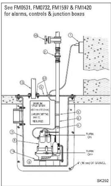
TYPICAL DEWATERING INSTALLATION
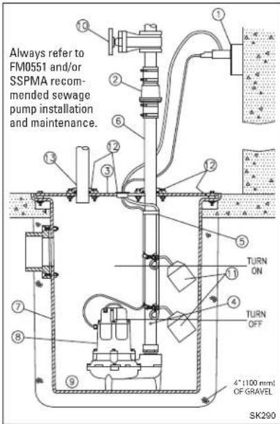
TYPICAL SEWAGE INSTALLATION
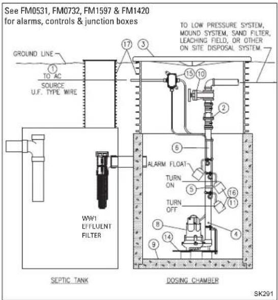
TYPICAL EFFLUENT INSTALLATION
All installations must comply with all applicable electrical and plumbing codes, including, but not limited to, National Electrical Code, local, regional, and/or state plumbing codes, etc. Not intended for use in hazardous locations.
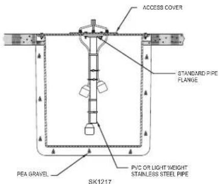
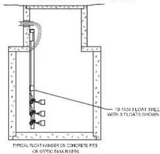
Suggested Methods of Float Installation
On some installations, it may be desirable to install an independent hanger for the level control switches to avoid possible hang-ups on the pumps, piping, valves, etc. Float hangers are available from Zoeller Company on Catalog Sheet FM0526 or can be fabricated from standard pipe and fittings.
TYPICAL FLOAT HANGER ON STEEL COVER PITS
TYPICAL FLOAT HANGER ON CONCRETE PITS
OR SEPTIC TANK RISERS
© Copyright 2023 Zoeller® Co. All rights reserved.
SK1218
WD & WH MODEL INSTALLATION
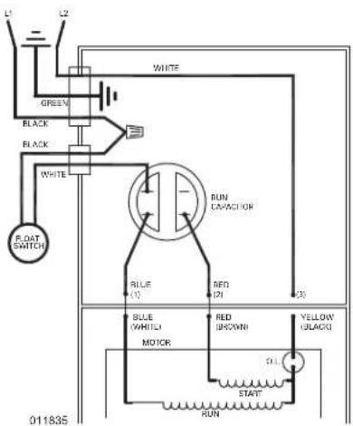
WIRING DIAGRAM FOR MODELS
WD - 230 V, 1 Ph, 60 Hz. WH - 200/208 V, 1 Ph, 60 Hz.
Determining Pumping Range in Inches (1 inch = 2.5 cm)
| Tether Length | 5 min. | 10 | 15 | 20 | 22 max. |
| Pumping Range | 9 | 13.5 | 18 | 22 | 24 |
Use only as a guide. Due to weight of cable, pumping range above horizontal is not equal to pumping range below horizontal. Ranges are based on testing in nonturbulent conditions. Range may vary due to water temperature and cord shape. As tether length increases, so does the variance of the pumping range.
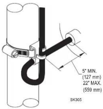
20 AMP SWITCH (WD & WH MODELS)
Models WD & WH are fully automatic. A float switch is included and factory-wired in the pump circuit to provide automatic operation once the float switch is secured properly to the outlet pipe. Use the diagram above to secure the float switch properly and obtain the proper tether to customize the on-off cycle to each application. Note: Failure to keep within proper tether limits may prevent reliable switch operation.
Note: Cable must be mounted in horizontal position.
SINGLE PHASE WIRING INSTRUCTIONS

⚠ WARNING FOR YOUR PROTECTION, ALWAYS DISCONNECT PUMP FROM ITS POWER SOURCE BEFORE HANDLING. Single phase pumps are supplied with a 3-prong grounded plug to help protect you against the possibility of electrical shock. DO NOT, UNDER ANY CIRCUMSTANCES, REMOVE THE GROUND
PIN. The 3-prong plug must be inserted into a mating 3-prong grounded receptacle. If the installation does not have such a receptacle, it must be changed to the proper type, wired and grounded in accordance with the National Electrical Code and all applicable local codes and ordinances.
⚠ WARNING Risk of electrical shock. Do not remove power supply cord and strain relief or connect conduit directly to the pump. ⚠ WARNING Installation and checking of electrical circuits and hardware should be performed by a qualified licensed electrician.

⚠ WARNING Units supplied without a plug (single and three phase) and single phase nonautomatic units with a 20 amp plug must have a motor control and liquid level control provided at time of installation. The control device should have suitable voltage, ampere, frequency, grounding and horsepower rating for the pump to which it is connected.
THREE PHASE WIRING INSTRUCTIONS

⚠ WARNING FOR YOUR PROTECTION, ALWAYS DISCONNECT PUMP FROM ITS POWER SOURCE BEFORE HANDLING.
To automatically operate a nonautomatic three phase pump, a control panel is required. Follow the instructions provided with the panel to wire the system. For automatic three phase pumps, see automatic 3 phase wiring diagram located to the far right.
Before installing a pump, check the pump rotation to ensure that wiring has been connected properly to power source, and that the green lead of power cord (see wiring diagram) is connected to a valid ground. Momentarily energize the pump, observing the directions of kick back due to starting torque. Rotation is correct if kick back is in the opposite direction of rotation arrow on the pump casing. If rotation is not correct, switching of any two power leads other than ground, should provide the proper rotation.
All three phase pumps require motor starting devices with motor overload protection. See FM0486 for duplex installations. Pumps must be installed in accordance with the National Electrical Code and all applicable local codes and ordinances. Pumps are not to be installed in locations classified as hazardous in accordance with National Electrical Code, ANSI/NFPA 70.
NONAUTOMATIC 3 PHASE
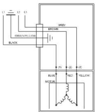
006848
AUTOMATIC 3 PHASE
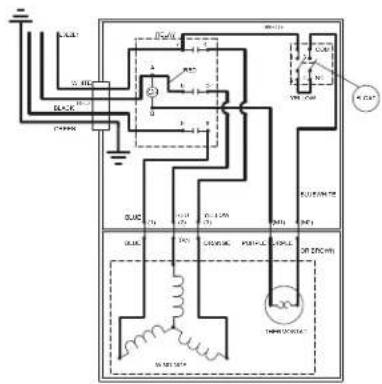
013071
IMPORTANT NOTICE: Some insurance policies, both commercial and residential, extend coverage for damages incurred by product failure. You will need to have possession of the product to support your claim in most cases. Zoeller Pump Co. will exchange the unit or refund the original purchase price once the claim is settled with the insurer in the case where you need to retain possession of the product to support a damage claim you submit to your insurance company.
Trusted. Tested. Tough.®
ZOELLER® PUMP COMPANY

FM0447S
Trusted. Tested. Tough.®
DATE D'INSTALLATION :
NUMÉRO DE MODÈLE :
ZOELLER® PUMP COMPANY

ADRESSE POSTALE : P.O. BOX 16437 • Louisville, KY 40256-0347 USA
ADRESSE PHYSIQUE : 3649 Cane Run Road • Louisville, KY 40211-1961 USA
TÉL : +1 (502) 778-2731 • 1-800-928-PUMP
FM0447F
Zoeller Pump Company
en ligne:
http://reg.zoellerpumps.com/

- Notice to installing contractor: Instructions must remain with installation.
- ZOELLER® PUMP COMPANY
- INSTALLATION INSTRUCTIONS
- RECOMMENDED MODELS
- PREINSTALLATION CHECKLIST - ALL INSTALLATIONS
- SEE BELOW FOR LIST OF WARNINGS
- SEE BELOW FOR LIST OF CAUTIONS
- LIMITED WARRANTY
- In instances where property damages are incurred as a result of an alleged product failure, the property owner must retain possession of the product for investigation purpose.
- DO'S & DON'T'S FOR INSTALLING UNIT
- RECOMMENDED INSTALLATION FOR ALL APPLICATIONS
- Suggested Methods of Float Installation
- WD & WH MODEL INSTALLATION
- SINGLE PHASE WIRING INSTRUCTIONS
- THREE PHASE WIRING INSTRUCTIONS
Brand : Zoeller
Model : M161
Category : Water pump