
PowerEdge 6850 - Server DELL - Free user manual and instructions
Find the device manual for free PowerEdge 6850 DELL in PDF.

| Product Type | 4U Rack Server |
| Dimensions (approx.) | 447 x 186 x 678 mm (W x H x D) |
| Weight (approx.) | 45 kg |
| Power Supply | Redundant power supplies (estimated 2 x 1470W) |
| Maximum Storage Capacity | Up to 5 x 3.5" or 8 x 2.5" drives |
| Supported Drive Type | SAS (Serial-Attached SCSI) |
| RAID Controller | Integrated SAS controller card (RAID option) |
| Drive Bays | Hot-swappable |
| Drive Indicators | Activity LED (green) and status LED (green/amber) |
| RAID Functions | Software RAID management, disk rebuild, identification |
| Backplane Connectors | SAS A, SAS B, power, control panel |
| Backplane Cards | 3.5" (5 drives) and 2.5" (8 drives) with interposer card |
| Controller Card Slot | Expansion slot 5 |
| Cooling | 4 fans, ventilation guards |
| Memory (estimated) | Up to 16 GB (not specified in manual) |
| Processors (estimated) | Dual Intel Xeon processor |
| Maintenance | Tool-less hard drive replacement, blanks required for empty bays |
| Safety | Disconnect power before servicing, ESD precautions, service by qualified technician |
| Available Replaceable Parts | SAS hard drives, SAS controller, backplanes, blanks, drive carriers |
| Diagnostic Software | Server Administrator |
Frequently Asked Questions - PowerEdge 6850 DELL
User questions about PowerEdge 6850 DELL
0 question about this device. Answer the ones you know or ask your own.
Ask a new question about this device
Download the instructions for your Server in PDF format for free! Find your manual PowerEdge 6850 - DELL and take your electronic device back in hand. On this page are published all the documents necessary for the use of your device. PowerEdge 6850 by DELL.
USER MANUAL PowerEdge 6850 DELL
Notes, Notices, and Cautions

NOTE: A NOTE indicates important information that helps you make better use of your computer.

NOTICE: A NOTICE indicates either potential damage to hardware or loss of data and tells you how to avoid the problem.

CAUTION: A CAUTION indicates a potential for property damage, personal injury, or death.
Information in this document is subject to change without notice.
© 2006 Dell Inc. All rights reserved.
Reproduction in any manner whatsoever without the written permission of Dell Inc. is strictly forbidden.
Trademarks used in this text: Dell and the DELL logo are trademarks of Dell Inc.
Other trademarks and trade names may be used in this document to refer to either the entities claiming the marks and names or their products.
Dell Inc. disclaims any proprietary interest in trademarks and trade names other than its own.
April 2006 P/N GJ242 Rev. A00
Contents
Features and Indicators 5
SAS Hard-Drive Indicator Codes 6
Installing SAS Hard Drives 8
Removing a Drive Blank 8
Installing a Drive Blank 9
Removing a Hot-Plug Hard Drive 9
Installing a Hot-Plug Hard Drive 10
Replacing a Hard Drive in a Hard-Drive Carrier 11
Replacing a SAS Controller Card 12
SAS Backplane Boards 13
SAS Backplane Connectors 13
Replacing a 3.5-Inch SAS Backplane. 14
Replacing a 2.5-Inch SAS Backplane. 14
SAS 2.5-Inch Peripheral Interposer Board 17
Peripheral Interposer Board Connectors. 17
Replacing a Peripheral Interposer Board 18
Troubleshooting 21
Troubleshooting a SAS Hard Drive 21
Troubleshooting a SAS Controller Card 23
This document provides information about the optional Serial-Attached SCSI (SAS) hard drives, related features, and procedures not covered in the system Installation and Troubleshooting Guide. The following topics are covered:
- Features and indicators
• Installing SAS hard drives - Replacing a SAS controller card
• SAS backplane boards
• SAS 2.5-inch peripheral interposer board - Troubleshooting
Features and Indicators
The basic features and indicators are described in the system Installation and Troubleshooting Guide. The key changes incorporated in systems with optional SAS hard drives include the following:
- Systems with SAS drives include a SAS controller expansion card, in place of the integrated SCSI controller. SAS A and SAS B connectors on the backplane are connected to the SAS controller card.
• Systems with SAS drives include a SAS backplane for either the 3.5-inch or 2.5-inch SAS hard drives.
• RAID capability for systems with internal SAS drives is provided by the SAS controller expansion card. - The RAID battery cable attaches to a connector on the SAS controller card, instead of to the battery connector on the system board. See Figure 1-5.
-
Systems with 2.5-inch SAS hard drives have the following additional changes incorporated:
-
The 2.5-inch SAS backplane (see Figure 1-7) is connected to an additional board, the 2.5-inch SAS peripheral interposer board (see Figure 1-10). The interposer board provides some of the connectors included on the 3.5-inch backplane.
- The control-panel cable is routed under the bay for fans 1 and 3 and connected to the back of the 2.5-inch SAS peripheral interposer board. (For 3.5-inch drives the control-panel cable connects to the front of the backplane on top of the hard drive bays.)
- The cooling shroud is modified to cover the space behind the hard drive bay, and cables and other components are altered to accommodate the 2.5-inch drive bay and boards. Figure 1-1 illustrates the inside of a 2.5-inch system.
Figure 1-1. Inside the 2.5-Inch SAS System

1 control panel 2 cooling shroud 3 memory riser card
4 expansion card slots (7) 5 fans (4) 6 diskette drive (optional)
7 optical drive (optional) 8 2.5-inch SAS hard drives (8)
SAS Hard-Drive Indicator Codes
The hard-drive carriers have two indicators—the drive-activity indicator and the drive-status indicator. See Figure 1-2. The drive-status indicator lights to indicate the status of the drive.
Figure 1-2. Hard-Drive Indicators
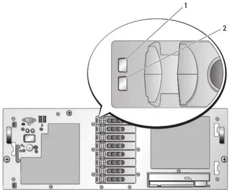
1 drive-status indicator (green and amber) 2 green drive-activity indicator
Table 1-1 lists the drive indicator patterns for RAID hard drives. Different patterns are displayed as drive events occur in the system. For example, if a hard drive fails, the "drive failed" pattern appears. After the drive is selected for removal, the "drive being prepared for removal" pattern appears, followed by the "drive ready for insertion or removal" pattern. After the replacement drive is installed, the "drive being prepared for operation" pattern appears, followed by the "drive online" pattern.
Table 1-1. Hard-Drive Indicator Patterns for RAID
| Condition Drive-Status Indicator Pattern | |
| Identify drive/preparing for removal | Blinks green two times per second |
| Drive ready for insertion or removal | OffNOTE: The drive status indicator is also off until all hard drives are initialized after system power is applied. Drives are not ready for insertion or removal during this time. |
| Drive predicted failure Blinks green, amber, and off. | |
| Drive failed Blinks amber four times per second. | |
| Drive rebuilding Blinks green slowly. | |
| Condition Drive-Status Indicator Pattern | |
| Drive online Steady green. | |
| Rebuild aborted Blinks green three seconds, amber three seconds, and off six seconds. | |
Installing SAS Hard Drives
This subsection describes how to install and configure SAS hard drives in the system's internal hard-drive bays. Your system features up to five 3.5-inch hard drives, or eight 2.5-inch hard drives. All drives connect to the system board through one of two optional SAS backplane boards. See "SAS Backplane Boards" on page 13 for information on these backplane options.
Hard drives are supplied in special hot-pluggable drive carriers that fit in the hard-drive bays.

NOTICE: Before attempting to remove or install a drive while the system is running, see the documentation for the SAS RAID controller card to ensure that the host adapter is configured correctly to support hot-plug drive removal and insertion.

NOTE: It is recommended that you use only drives that have been tested and approved for use with the SAS backplane boards.
You may need to use different programs than those provided with the operating system to partition and format SAS hard drives.

NOTICE: Do not turn off or reboot your system while the drive is being formatted. Doing so can cause a drive failure.
When you format a high-capacity hard drive, allow enough time for the formatting to be completed. Long format times for these drives are normal. A 9-GB hard drive, for example, can take up to 2.5 hours to format.
Removing a Drive Blank

NOTICE: To maintain proper system cooling, all empty hard-drive bays must have drive blanks installed. If you remove a hard-drive carrier from the system and do not reinstall it, you must replace the carrier with a drive blank.
The process for removing a drive blank depends on whether your system is configured with 3.5-inch or 2.5-inch hard drives.
For 3.5-inch hard drive configurations:
1 Remove the front bezel, if attached. See "Opening the System" in the Installation and Troubleshooting Guide.
2 Insert your finger under the shrouded end of the blank and press in on the latch to eject the blank outward from the bay.
3 Pry the ends of the blank outward until the blank is free.
For 2.5-inch hard drive configurations, remove the blank as you would the 2.5-inch hard drive carrier:
1 Remove the front bezel, if attached. See "Opening the System" in the Installation and Troubleshooting Guide.
2 Open the drive blank release handle to release the blank. See Figure 1-3.
3 Slide the drive blank out until it is free of the drive bay.
Installing a Drive Blank
The process for installing a drive blank depends on whether your system is configured with 3.5-inch or 2.5-inch hard drives.
For 3.5-inch hard drive configurations, the drive blank is keyed to ensure correct insertion into the drive bay. To install a 3.5-inch drive blank, insert and rotate in the keyed side of the blank into the drive bay and press evenly on the other end of the blank until it is fully inserted and latched.
For 2.5-inch hard drive configurations, install the hard drive blank the same way as you install a 2.5-inch hard drive carrier:
1 Remove the front bezel, if attached. See "Opening the System" in your Installation and Troubleshooting Guide
2 Open the handle on the drive blank.
3 Insert the drive blank into the drive bay until the blank is fully seated.
4 Close the handle to lock the blank in place.
5 Replace the front bezel, if it was removed in step 1.
Removing a Hot-Plug Hard Drive
1 Remove the front bezel, if attached. See "Opening the System" in your Installation and Troubleshooting Guide
2 From the RAID management software, prepare the drive for removal and wait until the hard-drive indicators on the drive carrier signal that the drive can be removed safely. See your SAS RAID controller documentation for information about hot-plug drive removal.
If the drive has been online, the green activity/fault indicator will flash as the drive is powered down. When both drive indicators are off, the drive is ready for removal.
3 Open the drive carrier release handle to release the drive. See Figure 1-3.
4 Slide the hard drive out until it is free of the drive bay.
5 If you do not replace the hard drive, insert a drive blank in the vacated drive bay. See "Installing a Drive Blank" on page 9.

NOTICE: To maintain proper system cooling, all empty hard-drive bays must have drive blanks installed.
Figure 1-3. Removing and Installing a Hot-Plug Hard Drive

1 hard drive 2 drive carrier 3 drive carrier release handle
Installing a Hot-Plug Hard Drive

NOTICE: When installing a hard drive, ensure that the adjacent drives are fully installed. Inserting a hard-drive carrier and attempting to lock its handle next to a partially installed carrier can damage the partially installed carrier's shield spring and make it unusable.

NOTICE: Not all operating systems support hot-plug drive installation. See the documentation supplied with your operating system.
1 Remove the front bezel, if attached. See "Opening the System" in your Installation and Troubleshooting Guide
2 If a drive blank is present in the bay, remove it. See "Removing a Drive Blank" on page 8.
3 Install the hot-plug hard drive.
a Open the handle on the hard-drive carrier.
b Insert the hard-drive carrier into the drive bay until the carrier contacts the backplane.
c Close the handle to lock the drive in place.
4 Replace the front bezel, if it was removed in step 1.
Replacing a Hard Drive in a Hard-Drive Carrier
To remove a SAS hard drive from a drive carrier, remove the four screws from the slide rails on the hard-drive carrier and separate the hard drive from the carrier.
To install a SAS hard drive in a drive carrier, perform the following steps:

NOTE: SAS hard drives must be installed only in SAS/SATAu drive carriers. The SAS/SATAu drive carrier has marks indicating the SAS and SATA mounting screws.
1 Insert the SAS hard drive into the hard-drive carrier with the connector end of the drive at the rear. See Figure 1-4.
2 Viewing the assembly as shown in Figure 1-4, a lign the bottom rear screw hole on the hard drive with the hole labeled "SAS" on the hard drive carrier.
When aligned correctly, the rear of the hard drive will be flush with the rear of the hard-drive carrier.
3 Attach the four screws to secure the hard drive to the hard-drive carrier. See Figure 1-4.
Figure 1-4. Installing a SAS Hard Drive Into a Drive Carrier

1 screws (4) 2 drive carrier 3 SAS hard drive
Replacing a SAS Controller Card

CAUTION: Any installation that requires removal of the system cover is intended solely to be performed by trained service technicians. See your Product Information Guide for complete information about safety precautions, working inside the computer, and protecting against electrostatic discharge.
See "Installing an Expansion Card" in the Installation and Troubleshooting Guide for instructions about removing and installing the card. Figure 1-5 illustrates the SAS and RAID battery connections. See the SAS controller documentation for use and configuration information.

NOTE: The SAS controller card must be installed in expansion slot 5.

NOTE: Ensure that the SAS A and SAS B cables are connected to the backplane and the SAS controller card connectors. Both cables must be installed for the drives to function.
Figure 1-5. Routing the SAS Controller Card Cables
1 SAS B 2 SAS A 3 RAID battery
4 SAS A 5 SAS B 6 battery connector
SAS Backplane Boards
There are two SAS backplane board options, one supporting up to five 3.5-inch drives, and the other supporting up to eight 2.5-inch drives. For the 2.5-inch option only, an additional board, the peripheral interposer board, provides some of the connectors (see "Peripheral Interposer Board Connectors" on page 17).
SAS Backplane Connectors
Figure 1-6 shows the location of the connectors on the 3.5-inch backplane board, and Figure 1-7 shows the location of the connectors on the 2.5-inch backplane board.
Figure 1-6. SAS Backplane Board Connectors: 3.5-inch Option

1 SAS A 2 data interface 3 power
4 control panel 5 SAS B 6 installation alignment slot
Figure 1-7. SAS Backplane Board Connectors: 2.5-inch Option
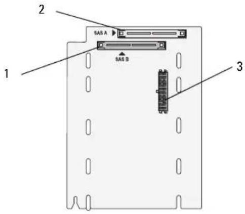
1 SAS B 2 SAS A 3 backplane power
Replacing a 3.5-Inch SAS Backplane

CAUTION: Any installation that requires removal of the system cover is intended solely to be performed by trained service technicians. See your Product Information Guide for complete information about safety precautions, working inside the computer, and protecting against electrostatic discharge.
To replace a 3.5-inch SAS backplane, follow the steps for removing and installing a SCSI backplane described in "SCSI Backplane" in the Installation and Troubleshooting Guide, substituting the connectors on the SAS backplane board for the corresponding connectors on the SCSI backplane board. See Figure 1-6 for the location of connectors on the 3.5-inch SAS backplane.
Replacing a 2.5-Inch SAS Backplane

CAUTION: Any installation that requires removal of the system cover is intended solely to be performed by trained service technicians. See your Product Information Guide for complete information about safety precautions, working inside the computer, and protecting against electrostatic discharge.
Removing a 2.5-Inch SAS Backplane
1 Turn off the system and attached peripherals, and disconnect the system from the electrical outlet.
2 Open the system. See "Opening the System" in the Installation and Troubleshooting Guide.

NOTICE: To prevent damage to the drives and backplane, you must remove the SAS drives and diskette/optical drive carrier from the system before removing the backplane. You must note the number of each hard drive and temporarily label them before removal so that you can replace them in the same locations.
3 Remove all SAS hard drives. See "Removing a Hot-Plug Hard Drive" on page 9.
4 Remove the optical drive/diskette drive carrier.
To remove the drive carrier, pull the release latch forward, then slide the carrier out of the chassis. See the Installation and Troubleshooting Guide.
5 Remove the cooling shroud. See "Removing the Cooling Shroud" in the Installation and Troubleshooting Guide
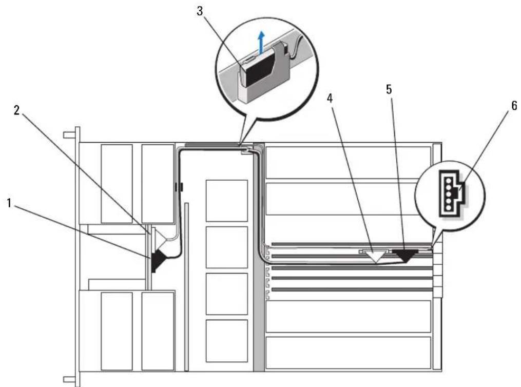
6 Disconnect the SAS and backplane power cables from the back of the SAS backplane.
For improved access, remove the SAS cable(s) from the clip that is attached to the fan-3 air guard and move the cable(s) away from the backplane. See Figure 1-8.
Figure 1-8. Cabling a 2.5-Inch SAS Backplane

1 SAS cable clip 2 SAS cables 3 fan-3 air guard 4 backplane power 5 SAS B 6 SAS A
7 Remove the SAS backplane:
a Press the spring-loaded blue retention tab at the back of the backplane, then slide the backplane upward. See Figure 1-9.
b When the backplane cannot slide upward any farther, pull the backplane toward the back of the system to remove it from the retention hooks.
c Lift the board out of the system, being careful to avoid damaging components on the face of the board.
d Place the SAS backplane face down on a work surface.
Figure 1-9. Removing and Installing a 2.5-Inch SAS Backplane

1 2.5-inch backplane 2 retention tab
Installing a 2.5-Inch SAS Backplane
1 Install the SAS backplane:
a Carefully lower the backplane into the system as shown in Figure 1-9, angling the top of the backplane slightly toward the back of the system. Be careful to avoid damaging components on the face of the board.
b Slide the retention slots on the backplane over the retention hooks on the chassis.
c Slide the backplane downward until the blue retention tab snaps into place.
2 Connect the SAS and backplane power cables to the back of the SAS backplane.
Secure the SAS cable(s) in the clip that is attached to the fan-3 air guard. See Figure 1-8.
3 Install the SAS hard drives in their original locations. See "Installing a Hot-Plug Hard Drive" on page 10.
4 Install the optical drive/diskette drive carrier.
Slide the drive carrier into its drive bay and press in the release latch. See the Installation and Troubleshooting Guide
5 Install the cooling shroud. See "Installing the Cooling Shroud" the Installation and Troubleshooting Guide.
6 Close the system. See "Closing the System" in the Installation and Troubleshooting Guide.
7 Reconnect the system to its electrical outlet and turn the system on, including any attached peripherals.
SAS 2.5-Inch Peripheral Interposer Board
In addition to the backplane, systems with 2.5-inch drives also have a peripheral interposer board, which contains some of the connectors that are on the 3.5-inch board and a backplane power connector.
Peripheral Interposer Board Connectors
Figure 1-10 presents a front view of the peripheral interposer board.
Figure 1-10. SAS Peripheral Interposer Board Connectors

1 control panel 2 power 3 backplane power
4 data interface 5 fans (2)
Replacing a Peripheral Interposer Board

CAUTION: Any installation that requires removal of the system cover is intended solely to be performed by trained service technicians. See your Product Information Guide for complete information about safety precautions, working inside the computer, and protecting against electrostatic discharge.
Removing a Peripheral Interposer Board
1 Turn off the system and attached peripherals, and disconnect the system from the electrical outlet.
2 Open the system. See "Opening the System" in the Installation and Troubleshooting Guide.
3 Remove the cooling shroud. See "Removing the Cooling Shroud" in the Installation and Troubleshooting Guide
4 Remove the processor filler blanks or heat sinks from processors 2 and 4. See "Removing a Processor" in the Installation and Troubleshooting Guide.
5 Disconnect the SAS and backplane power cables from the back of the SAS backplane. See Figure 1-8. For improved access, remove the SAS cable(s) from the clip that is attached to the fan-3 air guard and move the cable(s) away from the backplane. See Figure 1-8.
6 Disconnect the power cable from the top of the interposer board. See Figure 1-11.

NOTICE: When disconnecting the control-panel cable, hold the white pull-tab next to the control-panel cable connector to prevent damage to the interposer board or the cable itself.
7 Disconnect the control-panel cable from the control-panel cable connector on the top back of the interposer board. See Figure 1-11.
8 Disconnect the data interface cable from the back of the interposer board.
Figure 1-11. Cabling the Peripheral Interposer Board
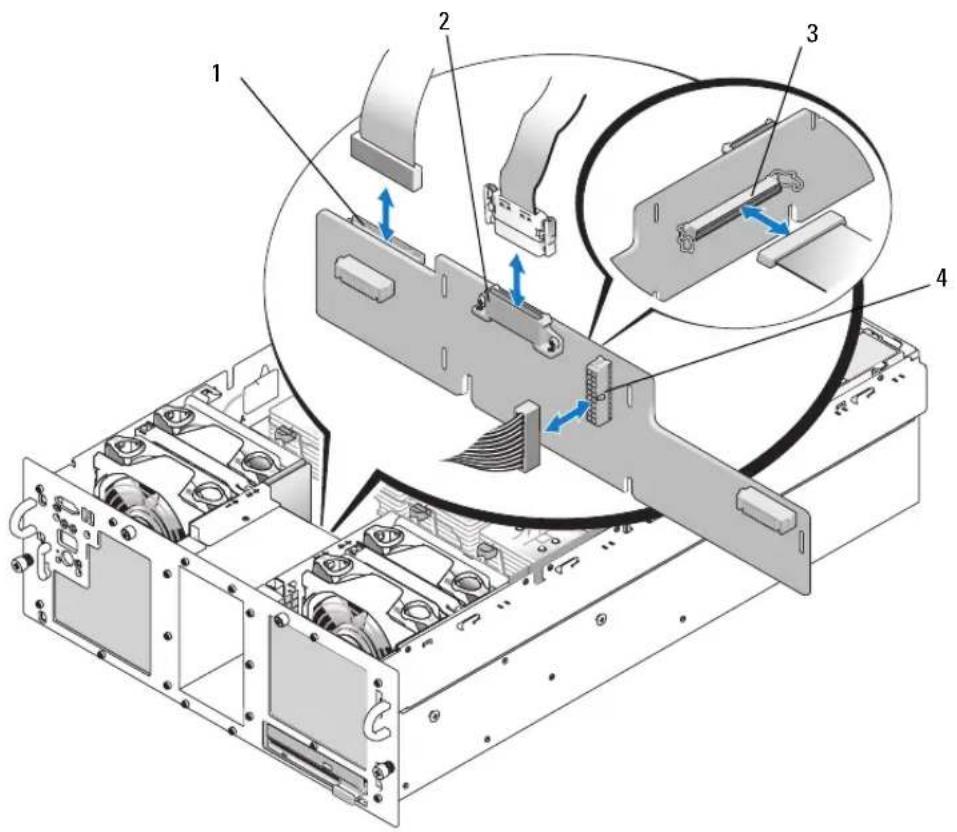
1 control panel 2 power 3 data interface cable
4 backplane power
9 Remove the peripheral interposer board:
a Press the spring-loaded blue retention tab at the back of the interposer board, then slide the board upward. See Figure 1-12.
b When the board cannot slide upward any farther, pull the board toward the back of the system to remove it from the retention hooks.
c Lift the board out of the system, being careful to avoid damaging components on the face of the board.
d Disconnect the backplane power cable from the front of the interposer board and place the backplane power cable aside. See Figure 1-11.
e Place the interposer board aside on a work surface.
Figure 1-12. Removing and Installing the Peripheral Interposer Board

1 retention tab 2 installation alignment slot 3 peripheral interposer board
Installing a Peripheral Interposer Board
1 Connect the backplane power cable to the front of the interposer board. See Figure 1-11.
2 Install the peripheral interposer board:
a Carefully lower the interposer board into the system, being careful to avoid damaging components on the face of the board. See Figure 1-12.
b Align the installation alignment slot on the bottom of the interposer board with the alignment pin on the bottom of the chassis.
c Slide the retention slots on the interposer board over the retention hooks on the chassis.
d Slide the board downward until the blue retention tab snaps into place.
3 Connect the data interface and control panel cables to the back of the interposer board. See Figure 1-11.
4 Connect the power cable to the top of the interposer board.
5 Connect the SAS and backplane power cables to the back of the SAS backplane. See Figure 1-8. Secure the SAS cable(s) in the clip that is attached to the fan-3 air guard. See Figure 1-8.
6 Install the processor filler blanks or heat sinks on processors 2 and 4. See "Installing a Processor" in the Installation and Troubleshooting Guide.
7 Install the cooling shroud. See "Installing the Cooling Shroud" the Installation and Troubleshooting Guide.
8 Close the system. See "Closing the System" in the Installation and Troubleshooting Guide.
9 Reconnect the system to its electrical outlet and turn the system on, including any attached peripherals.
Troubleshooting
The following sections provide guidelines for troubleshooting problems with SAS hard drives or the SAS controller card.
Troubleshooting a SAS Hard Drive
Problem
- Device driver error.
• One or more hard drives not recognized by the system.
Action

CAUTION: Any installation that requires removal of the system cover is intended solely to be performed by trained service technicians. Before performing any procedure, see your Product Information Guide for complete information about safety precautions, working inside the computer and protecting against electrostatic discharge.

NOTICE: This troubleshooting procedure can destroy data stored on the hard drive. Before you proceed, back up all files on the hard drive.
1 Run the appropriate online diagnostics test. See "Using Server Administrator Diagnostics" in the Installation and Troubleshooting Guide.
Depending on the results of the diagnostics test, proceed as needed through the following steps.
2 Remove the bezel. See "Opening the System" in the Installation and Troubleshooting Guide.
3 If you are experiencing problems with multiple hard drives, skip to step 9. For a problem with a single hard drive, continue to the next step.
4 Turn off your system, reseat the hard drive, and restart the system.
If the problem is not resolved, continue to the next step.
5 Restart the system and press
See the documentation supplied with the host adapter for information about the configuration utility.
6 Ensure that the hard drive has been configured correctly for the RAID.
7 Exit the configuration utility and allow the system to boot to the operating system.
8 Ensure that the required device drivers for your controller card are installed and are configured correctly. See the operating system documentation for more information.
9 Check the cable connections inside the system:
a Turn off the system, including any attached peripherals, and disconnect the system from the electrical outlet.
b Open the system. See "Opening the System" in the Installation and Troubleshooting Guide.
c Verify that the cable connections between the SAS backplane(s) and the SAS controller card are correct. See Figure 1-5.
d Verify that the SAS cables are securely seated in their connectors.
e Verify that the power connectors on the SAS backplane(s) are securely seated in their connectors.
f Close the system. See "Closing the System" in the Installation and Troubleshooting Guide.
g Reconnect the system to the electrical outlet, and turn on the system and attached peripherals.
If the problem persists, see "Getting Help" in the Installation and Troubleshooting Guide.
Troubleshooting a SAS Controller Card

NOTE: When troubleshooting a SAS controller card, also see the documentation for your operating system and the controller card.
Problem
- Error message indicates a problem with the SAS controller card.
- SAS controller card performs incorrectly or not at all.
Action

CAUTION: Any installation that requires removal of the system cover is intended solely to be performed by trained service technicians. Before performing any procedure, see your Product Information Guide for complete information about safety precautions, working inside the computer and protecting against electrostatic discharge.
1 Run the appropriate online diagnostic test. See "Using Server Administrator Diagnostics" in the Installation and Troubleshooting Guide.
2 Restart the system and press
3 Check the configuration settings, make any necessary corrections, and restart the system. If the problem is not resolved, continue to the next step.
4 Remove the bezel. See "Opening the System" in the Installation and Troubleshooting Guide.
5 Turn off the system and attached peripherals, and disconnect the system from its electrical outlet.
6 Open the system. See "Opening the System" in the Installation and Troubleshooting Guide.
7 Ensure that the controller card is firmly seated in its connector. See "Replacing a SAS Controller Card" on page 12.
8 Ensure that the following RAID components are properly installed and connected:
- Memory module
- Battery
9 Verify that the cable connections between the SAS backplane(s) and the SAS controller card are correct. See Figure 1-5.
10 Ensure that the cables are firmly connected to the SAS controller card and the SAS backplane board.
11 Close the system. See "Closing the System" in the Installation and Troubleshooting Guide.
12 Reconnect the system to its electrical outlet, and turn on the system and attached peripherals. If the problem persists, replace the SAS card battery. See "Replacing a SAS Controller Card" on page 12.
13 If replacing the battery does not solve the problem, see "Getting Help" in the Installation and Troubleshooting Guide.
1 SAS 电缆固定夹
2 SAS 电缆
3 风扇 3 空气护罩
4 背板电源
5 SAS B 6 SAS A
7 卸下 SAS 背板:
1
2.5 英寸背板
2
固定卡舌
安装2.5英寸SAS背板
1 安装 SAS 背板:
1 控制面板
2 电源
3 数据接口电缆
4 背板电源
9 卸下外围设备插入器板:
1 固定卡舌
2 安装定位槽
3 外围设备插入器板
安装外围设备插入器板
April 2006 P/N GJ242 Rev. A00
Inhalt
1 SAS ケーブルクリップ
2 SAS ケープル
3 ファン3のエアーガード
4 バックプレーン電源
5 SAS B 6 SAS A
1 コントロールパネル
2 電源
3 バックプレーン電源
4 データインタフェース
5 ファン (2)
周辺機器インターポーザボードの交換

1 コントロールパネル
2 電源
3 データインタフェースケーブル
4 バックプレーン電源
1 保持タプ
2 取り付け位置合わせスロット
3 周辺機器インターポーザボード
周辺機器インターポーザボードの取り付け
© 2006 Dell Inc. All rights reserved.
1 제어 패널
2 냉각기 덮개
3 메모리 라이저 카드
4 확장 카드 슬롯 (7)
5 팬 (4)
6 디스켓 드라이브(옵션)
7 광학 드라이브 (옵션)
1 SAS 케이블 클립
2 SAS 케이블
3 팬3 에어가드
4 후면 전원
5 SAS B 6 SAS A
7 SAS 후면 분리:
1 2.5 인치 후면 2 고정 탐
2.5 인치 SAS 후면 설치
1 SAS 후면 설치:
1 제어 패널
2 전원
3 데이터 인터페이스 케이블
4 후면 전원
9 주변 장착 보드 분리:
- Notes, Notices, and Cautions
- Contents
- Features and Indicators 5
- Installing SAS Hard Drives 8
- Replacing a SAS Controller Card 12
- SAS Backplane Boards 13
- SAS 2.5-Inch Peripheral Interposer Board 17
- Troubleshooting 21
- Features and Indicators
- SAS Hard-Drive Indicator Codes
- Installing SAS Hard Drives
- Removing a Drive Blank
- Installing a Drive Blank
- Removing a Hot-Plug Hard Drive
- Installing a Hot-Plug Hard Drive
- Replacing a Hard Drive in a Hard-Drive Carrier
- Replacing a SAS Controller Card
- SAS Backplane Boards
- SAS Backplane Connectors
- Replacing a 3.5-Inch SAS Backplane
- Replacing a 2.5-Inch SAS Backplane
- Removing a 2.5-Inch SAS Backplane
- Remove the SAS backplane:
- Installing a 2.5-Inch SAS Backplane
- SAS 2.5-Inch Peripheral Interposer Board
- Peripheral Interposer Board Connectors
- Replacing a Peripheral Interposer Board
- Removing a Peripheral Interposer Board
- Installing a Peripheral Interposer Board
- Troubleshooting
- Troubleshooting a SAS Hard Drive
- Problem
- Action
- Troubleshooting a SAS Controller Card
- 安装2.5英寸SAS背板
- 安装外围设备插入器板
- Inhalt
- 周辺機器インターポーザボードの交換
- 周辺機器インターポーザボードの取り付け
- 인치 SAS 후면 설치
Brand : DELL
Model : PowerEdge 6850
Category : Server