
EC1433H - Compressor HiKOKI - Free user manual and instructions
Find the device manual for free EC1433H HiKOKI in PDF.
| Product Type | High Pressure Air Compressor |
| Brand | HiKOKI |
| Model | EC1433H |
| Power Supply | 230 V~, 50 Hz |
| Rated Current | 5.2 A |
| Motor Power | 950 W (1.27 HP) |
| Max Reservoir Pressure | 32.5 bars (471.4 psi) |
| Max Pressure Side H (High Pressure) | 25 bars (362.6 psi) |
| Max Pressure Side L (Standard) | 8 bars (116 psi) |
| Protection Class | IP20 |
| Service Temperature | +5 to +40 °C |
| Operating Humidity | ≤85% RH, non-condensing |
| Sound Pressure Level | 72 dB(A) |
| Grounding | Class I, 3-pole cable |
| Safety Device | Automatic protection against overvoltage, undervoltage, and overheating |
| Maintenance | Drain the reservoir daily or after 4 hours of use |
| Spare Parts | Use only genuine HiKOKI parts |
| Warranty | Complies with national regulations |
| Manufacturer | HiKOKI, Parc de l'Eglantier, Lisses, France |
Frequently Asked Questions - EC1433H HiKOKI
User questions about EC1433H HiKOKI
0 question about this device. Answer the ones you know or ask your own.
Ask a new question about this device
Download the instructions for your Compressor in PDF format for free! Find your manual EC1433H - HiKOKI and take your electronic device back in hand. On this page are published all the documents necessary for the use of your device. EC1433H by HiKOKI.
USER MANUAL EC1433H HiKOKI
natural_image
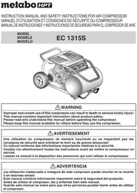
Illustration of a portable air purifier with wheels and control knobs (no text or symbols)Read through carefully and understand these instructions before use. Diese Anleitung vor Benutzung des Werkzeugs sorgfältig durchlesen und verstehen. Lire soigneusement et bien assimiler ces instructions avant usage. Prima dell'uso leggere attentamente e comprendere queste instruzioni. Deze gebruiksaanwijzing s.v.p. voor gebruik zorgvuldig doorlezen. Leer cuidadosamente y comprender estas instrucciones antes del uso. Antes de usar, leia com cuidado para assimilar estas instruções.
Handling instructions Bedienungsanleitung Mode d'emploi Istruzioni per l'uso Gebruiksaanwijzing Instrucciones de manejo Instruções de uso

natural_image
Diagram of a vehicle with a crosshair overlay, no text or symbols present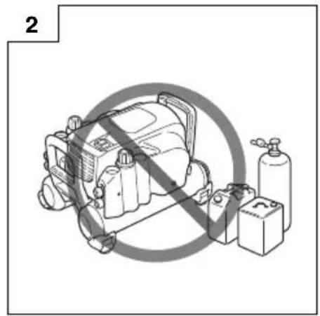
natural_image
Diagram of a mechanical device with no visible text, numbers, or symbols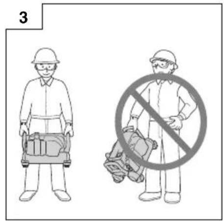

natural_image
Mechanical diagram showing two connected motors mounted on a platform, with motion lines indicating movement (no text or symbols present)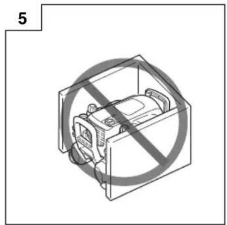
natural_image
Diagram of a device enclosed in a prohibition symbol, no text or labels present

| English Deutsch Français Italiano | ||||
| 1 | Drain lever Ablasshebel Levier de purge Leva di scarico | |||
| 2 | Pressure-reduction valve adjustment handle (L) | Druckminderventil-Einstellhebel (L) | Levier de réglage du détendeur (L) | Regolatore valvola di riduzione della pressione (L) |
| 3 | Pressure-reduction valve adjustment handle (H) | Druckminderventil-Einstellhebel (H) | Levier de réglage du détendeur (H) | Regolatore valvola di riduzione della pressione (H) |
| 4 | Pressure gauge Manometer | Jauge de pression Manometro | ||
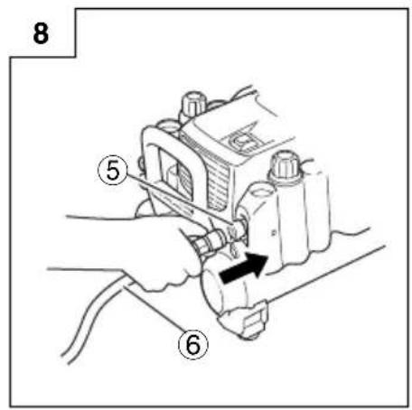
| 5 | Air socket Luftanschluss Raccord d'air Attacco aria | |||
| 6 | Air hose Luftschlauch Tuyau d'air Tubo dell'aria | |||
| Nederlands Español | Português | ||
| 1 | Aftaphendel | Palanca de drenaje | Alavanca de drenagem |
| 2 | Instelhendel van reduceerventiel (L) | Asa de ajuste de la válvula reductora de presión (L) | Manípulo de ajuste da válvula de redução da pressão (L) |
| 3 | Instelhendel van reduceerventiel (H) | Asa de ajuste de la válvula reductora de presión (H) | Manípulo de ajuste da válvula de redução da pressão (H) |
| 4 | Drukmeter | Manómetro | Manómetro |
| 5 | Luchtaansluiting | Manguito de aier | Tomada de ar |
| 6 | Luchtslang | Manguera de aire | Mangueira de ar |
| Symbols⚠ WARNINGThe following show symbols used for the machine. Be sure that you understand their meaning before use. | Symbole⚠ WARNINGDie folgenden Symbole werden für diese Maschine verwendet. Achten Sie darauf, diese vor der Verwendung zu verstehen. | Symboles⚠ AVERTISSEMENTLes symboles suivants sont utilisés pour l'outil. Bien se familiariser avec leur signifi cation avant d'utiliser l'outil. | Simboli⚠ AVVERTENZADi seguito mostriamo i simboli usati per la macchina.Assicurarsi di comprenderne il signifi cato prima dell'uso. | |
 | Read all safety warnings and all instructions.Failure to follow the warnings and instructions may result in electric shock, fi re and/or serious injury. | Lesen Sie sämtliche Sicherheitshinweise und Anweisungen durch.Wenn die Warnungen und Anweisungen nicht befolgt werden, kann es zu Stromschlag, Brand und/oder ernsthaften Verletzungen kommen. | Lire tous les avertissements de sécurité et toutes les instructions.Tout manquement à observer ces avertissements et instructions peut engendrer des chocs électriques, des incendies et/ou des blessures graves. | Leggere tutti gli avvertimenti di sicurezza e tutte le istruzioni.La mancata osservanza degli avvertimenti e delle istruzioni potrebbe essere causa di scosse elettriche, incendi e/o gravi lesioni. |
 | Always wear eye protection. | Tragen Sie immer einen Augenschutz. | Toujours porter des verres de protection. | Indossate sempre le protezioni oculari. |
 | Only for EU countriesDo not dispose of electric tools together with household waste material!In observance of European Directive 2012/19/EU on waste electrical and electronic equipment and its implementation in accordance with national law, electric tools that have reached the end of their life must be collected separately and returned to an environmentally compatible recycling facility. | Nur für EU-LänderWerfen Sie Elektrowerkzeuge nicht in den Hausmüll!Gemäss Europäischer Richtlinie 2012/19/EU über Elektro- und Elektronik-Altgeräte und Umsetzung in nationales Recht müssen verbrauchte Elektrowerkzeuge getrennt gesammelt und einer umweltgerechten Wiederververitung zugeführt werden. | Pour les pays européens uniquementNe pas jeter les appareils électriques dans les ordures ménagères!Conformément à la directive européenne 2012/19/UE relative aux déchets d'équipements électriques ou électroniques (DEEE), et à sa transposition dans la législation nationale, les appareils électriques doivent être collectés à part et être soumis à un recyclage respectueux de l'environnement. | Solo per Paesi UENon gettare le apparecchiature elettriche tra i rifi uti domestici.Secondo la Direttiva Europea 2012/19/UE sui rifi uti di apparecchiature elettriche ed elettroniche e la sua attuazione in conformità alle norme nazionali, le apparecchiature elettriche esauste devono essere raccolte separatamente, al fi ne di essere reimpiegate in modo eco-compatible. |
 | Symbolen⚠ WAARSCHUWINGHieronder staan symbolen afgebeeld die van toepassing zijn op deze machine. U moet de betekenis hiervan begrijpen voor gebruik. | Símbolos⚠ ADVERTENCIAA continuación se muestran los símbolos usados para la máquina. Asegúrese de comprender su signifi cada antes del uso. | Símbolos⚠ AVISOA seguir aparecem os símbolos utilizados pela máquina. Assimile bem seus signifi cados antes do uso. | |
 | Lees alle waarschuwingen en instructies aandachtig door.Nalating om de waarschuwingen en instructies op te volgen kan in een elektrische schok, brand en/of ernstig letsel resulteren. | Lea todas las instrucciones y advertencias de seguridad.Si no se siguen las advertencias e instrucciones, podría producirse una descarga eléctrica, un incendio y/o daños graves. | Leia todas as instruções e avisos de segurança.Se não seguir todas as instruções e os avisos, pode provocar um choque eléctrico, incéndio e/ou ferimentos graves. | |
 | Draag altijd oogbescherming. | Utilice siempre una protección ocular. | Utilize sempre protecção para os olhos. | |
 | Alleen voor EU-landenGeef elektrisch gereedschap niet met het huisvuil mee!Volgens de Europese richtlijn 2012/19/EU inzake oude elektrische en elektronische apparaten en de toepassing daarvan binnen de nationale wetgeving, dient gebruikt elektrisch gereedschap gescheiden te worden ingezameld en te worden afgevoerd naar een recycle bedrijf dat voldoet aan de geldende milieu-eisen. | Sólo para países de la Unión Europea¡No deseche los aparatos eléctricos junto con los residuos domésticos!De conformidad con la Directiva Europea 2012/19/UE sobre residuos de aparatos eléctricos y electrónicos y su aplicación de acuerdo con la legislación nacional, las herramientas eléctricas cuya vida útil haya llegado a su fi n se deberán recoger por separado y trasladar a una planta de reciclaje que cumpla con las exigencias ecológicas. | Apenas para países da UENão deite ferramentas eléctricas no lixo doméstico!De acordo com a directiva europeia 2012/19/UE sobre ferramentas eléctricas e electrónicas usadas e a transposição para as leis nacionais, as ferramentas eléctricas usadas devem ser recolhidas em separado e encaminhadas a uma instalação de reciclagem dos materiais ecológica. |
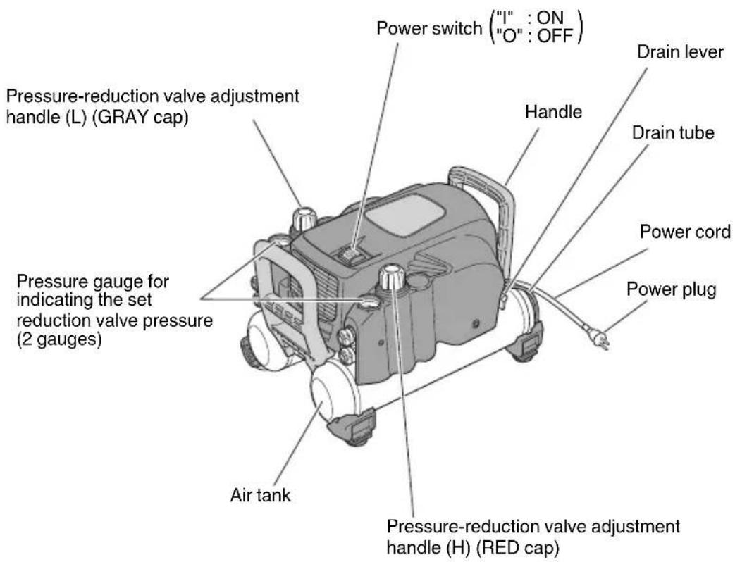
DESCRIPTION OF FUNCTIONS OF KEY COMPONENTS
| Power switch Turns on or off the power supply | |
| Pressure-reduction valve adjustment handle (H) (RED cap) | Intended for exclusive use with the super nailer. It adjusts the operating pressure of the HiKOKI high pressure tool. |
| Pressure-reduction valve adjustment handle (L) (GRAY cap) | Adjusts the pressure supplied to the general-purpose nailers and pneumatic tools (operating air pressure 8 bar (116 psi) maximum). |
| Pressure gauge in the tank Indicates pressure in the tank. | The pressure increases up to 32.5 bar. (471.4 psi) |
| Pressure gauge for indicating the set reduction valve pressure (2 gauges) | It indicates the set pressure on the pressure-reduction valves (H) and (L).(25 bar (362.6 psi) maximum on the H side and 8 bar (116 psi) maximum on the L side.) |
| High pressure air socket (for HiKOKI high pressure tools) It | connects the HiKOKI high pressure air hose for the HiKOKI high pressure tools. |
| Regular pressure air socket (for regular pressure tools) It | connects the air hose for the regular-pressure nailers. |
| Drain lever It drains compressed air and water, Drain once when the work is fi nished or more a day. | |
| Power plug It is usable with a triode ground outlet. |
SAFETY WARNINGS
WARNING

To avoid severe personal injury or property damage. Before using the tool, read carefully and understand the following "SAFETY WARNINGS":
Failure to follow warnings could result in death or serious injury.
PRECAUTIONS ON USING THE COMPRESSOR
Important information
Most accidents that result from compressor operation and maintenance are caused by the failure to observe basic safety rules or precautions. An accident can often be avoided by recognizing a potentially hazardous situation before it occurs, and by observing appropriate safety procedures. Basic safety precautions are outlines in the "SAFETY" section of this Instruction Manual and in the sections which contain the operation and maintenance instructions.
Hazards that must be avoided to prevent bodily injury or machine damage are identified by WARNINGS on the compressor and in this Instruction Manual.
Never use this compressor in a manner that has not been specifically recommended by manufacturer, unless you first confirm that the planned use will be safe for you and others.
Death or serious bodily injury could result from improper or unsafe use of compressor, to avoid these risks, follow these basic safety instructions.
High pressure compressor provides both high pressure and regular pressure air. For usage of high pressure air, high pressure compressor is designed only for HiKOKI high pressure nailers and high pressure air hose. Unspecified usage will cause serious accidents.
1. Never touch moving parts
Never place your hands, fingers or body parts near the compressor's moving parts.
2. Never operate without all guards in place
Never operate the compressor without all guards or safety features in place and in proper working order. If maintenance or servicing requires the removal of a guard or safety features, be sure to replace the guards or safety feature before resuming operation of the compressor.
3. Always wear eye protection

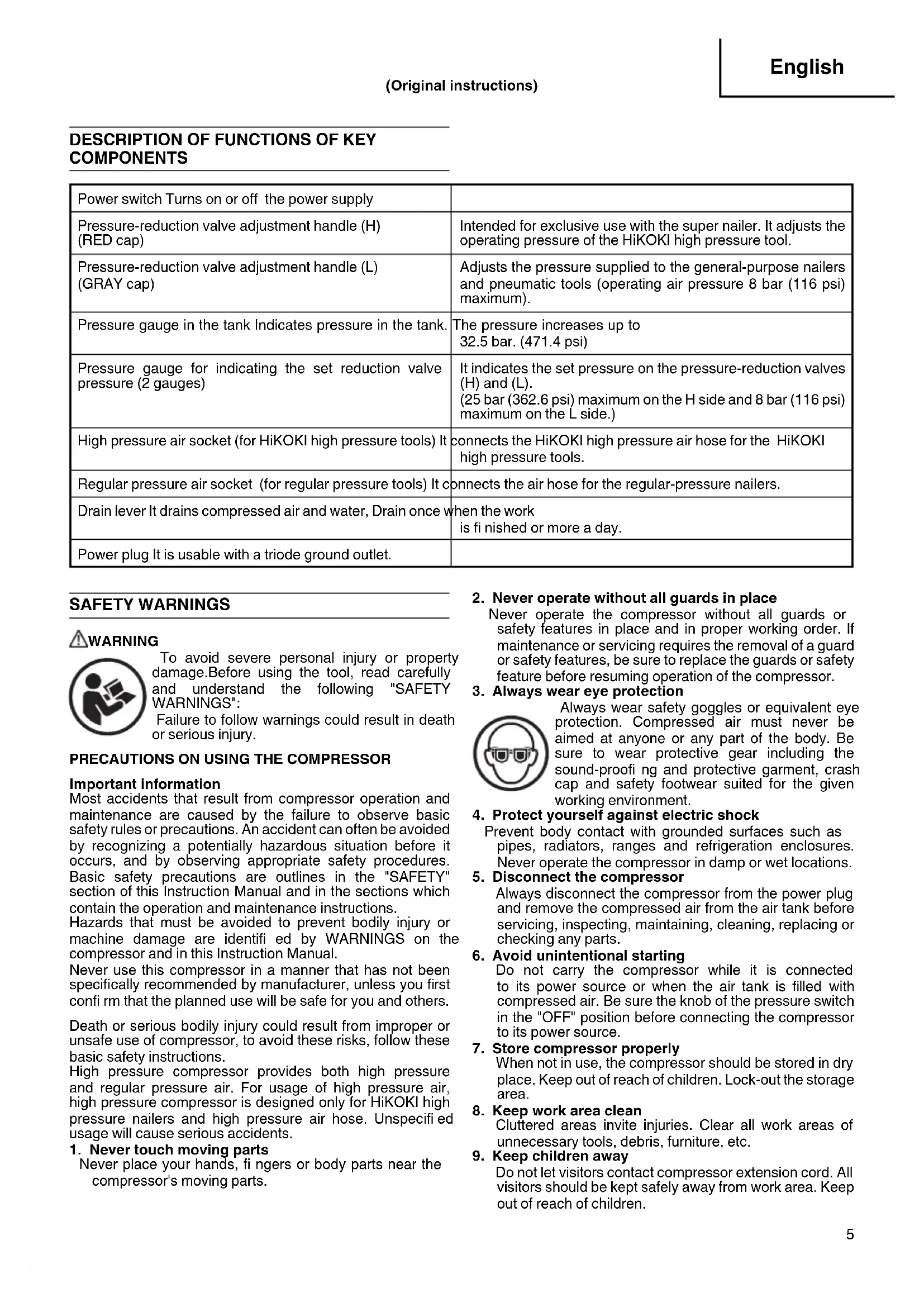
Always wear safety goggles or equivalent eye protection. Compressed air must never be aimed at anyone or any part of the body. Be sure to wear protective gear including the sound-proofing and protective garment, crash cap and safety footwear suited for the given working environment.
4. Protect yourself against electric shock
Prevent body contact with grounded surfaces such as pipes, radiators, ranges and refrigeration enclosures. Never operate the compressor in damp or wet locations.
5. Disconnect the compressor
Always disconnect the compressor from the power plug and remove the compressed air from the air tank before servicing, inspecting, maintaining, cleaning, replacing or checking any parts.
6. Avoid unintentional starting
Do not carry the compressor while it is connected to its power source or when the air tank is filled with compressed air. Be sure the knob of the pressure switch in the "OFF" position before connecting the compressor to its power source.
7. Store compressor properly
When not in use, the compressor should be stored in dry place. Keep out of reach of children. Lock-out the storage area.
8. Keep work area clean
Cluttered areas invite injuries. Clear all work areas of unnecessary tools, debris, furniture, etc.
9. Keep children away
Do not let visitors contact compressor extension cord. All visitors should be kept safely away from work area. Keep out of reach of children.
10. Dress properly
Do not wear loose clothing or jewelry. They can be caught in moving parts. Wear protective hair covering to contain long hair.
11. Don't abuse power cord
Never yank it to disconnect from receptacle. Keep power cord from heat, oil and sharp edges.
12. Maintain compressor with care
Follow instructions for lubricating. Inspect cords periodically and if damaged, have repaired by authorized service facility.
13. Use a safe extension cord
In order to prevent an electric shock, use a 3-core extension cord with a 3-pole earthing plug and a 3-core earthing plug socket.
Make sure that the extension cord is in the good working condition. If the cord is damaged, replace or repair it. The cord should have a sufficient capacity for the current running to the product. The cord of an insufficient capacity will cause a voltage drop or an electric power loss, resulting in overheating.
The following table shows the cord size used depending on the cord length. If the compressor is to be used outdoors, use an exclusive extension cord.
Table 1 Section valid for a max length of 20m (65')
| Compressor HP | W 230 V | (mm | ^2 ) |
| EC1433H 1.27 | 950 2.5 |
WARNING
Avoid electrical shock hazard. Never use this compressor with a damaged or frayed electrical cord or extension cord. Inspect all electrical cords regularly. Never use in near water or in any environment where electric shock is possible.
14. Stay alert
Watch what you are doing. Use common sense. Do not operate compressor when you are tired. Compressor should never be used by you if you are under the influence of alcohol, drugs or medication that makes you drowsy.
15. Check damaged parts and air leak
Before further use of the compressor, a guard or other part which is damaged should be carefully checked to determine that it will operate properly and perform its intended function.
Check for alignment of moving parts, binding of moving parts, breakage of parts, mounting, air leak, and any other conditions that may affected its operation.
A guard or other part that is damaged should be properly repaired or replaced by an authorized service facility unless otherwise indicated elsewhere in this Instruction Manual. Have defective pressure controllers replaced by authorized service facility.
Do not use compressor if switch does not turn it on and off.
16. Operate compressor correctly
Operate the compressor according to the instructions provided herein. Never allow the compressor to be operated by children, individuals unfamiliar with its operation or unauthorized personal.
17. Keep all screws, bolts and covers tightly in place
Keep all screws, bolts, and plates tightly mounted.
Check their conditions periodically.
18. Keep motor air vent clean
The motor air vent must be kept clean so that air can freely flow at all times. Check for dust build-up frequently.
19. Operate compressor at the rated voltage
Operate the compressor at voltages specified on their nameplates. If using the compressor at a higher voltage than the rated voltage, it will result in abnormally fast motor revolution and may damage the unit and burn out the motor.
20. Never use a compressor which is defective or operating abnormally
If the compressor appears to be operating unusually, making strange noises, or otherwise appears defective, stop using it immediately and arrange for repairs by an authorized service facility.
21. Do not wipe plastic parts with solvent
Solvent such as gasoline, thinner, benzine, carbon tetrachloride, and alcohol may damage and crack plastic parts. Do not wipe them with such solvents. Wipe plastic parts with a soft cloth lightly dampened with mild detergent and dry thoroughly.
22. Use only genuine replacement parts
Replacement parts not original may void your warranty and can lead to malfunction and resulting injuries. Genuine parts are available from your dealer.
23. Do not modify the compressor
Do not modify the compressor. Always contact the authorized service facility any repairs. Unauthorized modification may not only impair the compressor performance but may also result in accident or injury to repair personnel who do not have the required knowledge and technical expertise to perform the repair operations correctly.
24. Turn off the switch when the compressor is not used
When the compressor is not used, turn the switch OFF, disconnect the plug from the power source and open the drain cock to discharge the compressed air from the air tank.
25. Never touch the surface of the high-temperature section
In order to prevent a burn, do not touch the piping, head, cylinder, motor and inverter case.
26. Do not direct air stream at body
Risk of injury, do not direct compressed air at persons or animals.
27. Drain tank
Drain tank daily or after 4 hours of use.
Open drain cock and tilt compressor to empty accumulated water.
28. Do not stop compressor by pulling out the plug Use the "ON/OFF" switch.
- Make sure the compressor outlet pressure is set lower than the maximum operating pressure of the tool.
Too much air pressure causes a hazardous risk of bursting. Check the manufacturer's maximum pressure rating for air tools and accessories. The reducer outlet pressure must never exceed the maximum pressure rating.
30. Whenever using the high pressure side of the HiKOKI high pressure compressor, the genuine parts for the HiKOKI high pressure tools, high pressure air hose and compressor must be used.
31. Replacement parts
When servicing, use only HiKOKI genuine parts. Repair should be conducted only by authorized service facility.
-
Never use a transformer for the power supply of this compressor. Using a transformer to increase the voltage will cause a failure or burnout. (If a transformer is used, operation of the machine will stop.)
-
Never connect the compressor to an engine generator or direct-current power supply
The compressor will break or be damaged from burning.
- This compressor is for indoor use. Do not install the compressor in any place exposed to rain or splashed water, high-humidity place or high-temperature place (Fig. 1)
If used in the wet condition, it could produce an electric shock or be short-circuited, resulting in ignition. Use it under the environmental conditions provided by its specifications.
-
Do not operate the tool near a fl ammable substance Never operate the tool near a flammable substance (e.g., thinner, gasoline, etc.). (Fig. 2) Volatile fumes from these substances could be drawn into the compressor and compressed together with the air and this could result in an explosion.
-
Never use the tool in an explosive atmosphere
Sparks from the tool may ignite atmospheric gases, dust or other combustible materials.
- Be sure to earth the compressor
Earth the compressor to prevent a worker from getting an electric shock. It comes with a 3-pole cord and a 3-pole earthing plug so that it can be connected to an appropriate earthing plug socket.
A green-and-yellow striped wire is an earthing conductor. Never connect it to other charged terminals.
- When carrying the compressor, hold it correctly.
Carry the compressor in a proper manner by holding its grips with both hands. (Fig. 3)
-
Take care to transport the compressor correctly, do not overturn it or lift it with hooks or ropes.
-
When disposing the machine or tis parts, follow the relevant national rules.
SPECIFICATIONS
| Model EC1433H | |
| Power supply 230 V AC 50Hz | |
| Rated current 5.2 A | |
| Motor power 950 W (1.27 HP) | |
| Protective earthing Class I | |
| Protective structure IP20 | |
| Working temperature | 5°C to +40 °C |
| Working humidity 85 % RH or less. No dew condensation. | |
| Height above sea level | Up to 1000 m |
| Storage temperature | -10 to +50 °C |
| Storage humidity | 85 % RH or less. No dew condensation. |
| Pressure switch working range | Off: 3.25 MPa (32.5 bar) [471.4 psi]/On: 2.6 MPa (26 bar) [377.1 psi] |
INSTRUCTIONS FOR OPERATION
Unpack the compressor and check for any deficiency, damage caused during transportation and loose bolts and screws.
WARNING
Read section titled "SAFETY WARNINGS"
Wear safety glasses or goggles
Danger to the eyes always exists due to the possibility of dust being blown up by the exhausted air or of a fastener flying up to the improper handling of the tool. For these reasons, safety glasses or goggles shall always be worn when operating the tool.
NOTE:
○ Non-side shielded spectacles and face shields alone do not provide adequate protection.
☐ The information contained in this Instruction Manual is designed to assist you in the safe operation and maintenance of the compressor.
Some illustrations in this Instruction Manual may show details or attachments that differ from those on your own compressor.
1. Installation
WARNING
☐ Never use the machine in a place where any volatile combustible substance has been stored. (Fig. 2)
Never use it near gasoline, thinner, gas, paint or adhesive agent, because they could be ignited or blow up.
○ Never use the machine near the heat of fire or any combustible substance.
Never use the machine in an unstable place. (Fig. 4) Never use it in a place where it could move or fall of itself. Be sure to install the compressor on a flat floor, with leg rubber underneath it; the allowable tilt angle of the floor is up to 10 degrees. If the installation floor is tilted and slippery, ensure that the compressor does not move during operation. Do not use it on a shelf or a stand where it may fall or tumble.
○ Avoiding a place exposed to high temperature or the direct sunshine, be sure to use the machine in the well-ventilated shade.
Using it under high temperature or in the direct sunshine not only deteriorates its durability, but increases the temperature of the main body, causing danger to your safety.
Be sure to use it in the well-ventilated shade. The adequate room temperature is +5°C to +40°C.
Do not install the machine in a dusty (wooden chips, etc.) Place.
○ Install the machine in the appropriate direction.
Install it appropriately.
Never install the machine in the rain or in a place splashed with water or exposed to high temperature. (Fig. 1)
Using it in the wet condition could cause an electric shock or a short-circuit, resulting in a fire due to burnout or ignition.
Never block a ventilation opening or use the machine in a box or a narrow place (in a vehicle, etc.) (Fig. 5)
Neglect of this may generate abnormal heat, causing a trouble or an accident.
Install the compressor at the distance of 1 m or more from the wall to secure sufficient ventilation and cooling.
○ Never sit or place an object on the top of the machine.
Neglect of this could cause a trouble or break it.
Do not use the compressor in any place where the temperature is 5^ C or less or the ambient temperature exceeds +40^ C.
2. Name of parts

3. Machine operating procedure
Inspection and checkup prior to operation
WARNING
○ Prior to use, check the bolts and nuts for loosening and the parts for missing one.
☐ The power supply used must 230 VAC 10 A and provided with a circuit breaker. Allowable source voltage range is +/-10%.
○ Width and length of the extension cord or drum cord used must be 2.5 mm ^4 minimum and 20 m maximum, respectively. And the cord must be fully drawn out when used.
○ Make sure the machine is installed in the right direction when using it.
- Use the machine in compliance with the instructions provided in "SAFTY WARNINGS" on page 5.
- Pressure values in the description do not include the error in reading the pressure gauge.
(1) After turning off the machine power switch, connect the earthing plug of the power plug to ground and then connect the power plug to the outlet.
When using an extension cord or drum cord, make sure its effective cross section and length are 2.5 mm ^2 minimum and 20 m maximum, respectively.
(2) Turn the power switch on while maintaining the drain lever fully open.
(3) Make sure that the motor starts to run and the air is leaking from the drain tube when the drain lever is open.
(4) Close the drain cock and make sure no air is leaking from the tube. (Fig. 6)
(5) Turn the adjustment handle (in 2 locations) of the pressure-reduction valve fully clockwise until you cannot move it anymore and make sure that the above operation moves the pressure gauge pointer (upward) at both locations.
CAUTION
As the pressure in the air tank increases due to the pressure characteristic of the pressure-reduction valve, the pressure can vary from the set supply pressure by as much as 2 bar.
Turn the pressure-reduction valve's adjustment handle counterclockwise once to reduce the pressure and then proceed to the adjustment while increasing the pressure by turning the adjusting hand clockwise.
(6) Make sure that the compression operation is automatically stopped in 6 to 7 minutes. Except when auxiliary tank is connected or voltage drop occurred, since these extends the operating hours.
(7) Wait for 5 minutes after the operation is stopped to confirm that there are no abnormal noises or air leakages and that the compressor does not restart.
(8) Discharge the compressed air by opening the drain lever somewhat. Make sure that the operation is resumed due to a decrease in the pressure.
(9) Close the drain lever and turn the power off while the compression operation is turned on to make sure that these actions stop the machine from operating.
(10) Turn the adjustment handle (in 2 locations) of the pressure-reduction valve counterclockwise to make sure that this turning moves the pressure gauge pointer downward at both locations. (You may hear sounds due to air leaking but it does not mean there is a failure.) (Fig. 7)
(11) Open the drain lever to discharge all the compressed air and water in the air tank.
If you found any abnormalities in the checkup or inspection prior to the operation, send the machine to your dealer or authorized service facility for inspection or repair.
Operating procedure
Before operating the machine, be sure to carry out the "Inspection and checkup prior to operation" described on page 9.
(1) Fully open the drain lever and turn the power switch on. After the operation has started, close the drain lever tight to increase the pressure.
(2) After confirming the operation has stopped due to the increased pressure, turn the adjustment handle of the pressure-reduction valve to adjust the operating pressure of the nailer and pneumatic tool to the appropriate level. When adjusting the pressure, turn the pressure-reduction valve's adjustment handle counterclockwise to set the pressure at a level lower than the appropriate value by 2 bars once. Then proceed to the adjustment while increasing the pressure by turning the handle clockwise. (Fig. 7)
○ Make sure to start the adjustment at a level lower than the appropriate pressure and continue the adjustment while increasing the pressure from that level upward. If you start the adjustment from a level higher than the appropriate value, an error results between the pressure gauge value and actually used pressure. (Due to Characteristics of pressure-reduction valve respectively)
☐ 2 pressure-reduction valves provided on this machine allow you to connect HiKOKI high pressure tools and the general-purpose nailer or pneumatic tool.
Allows connection and use of HiKOKI high pressure tools (of operating pressure of 25 bars maximum)
Allows connection and use of the general-purpose nailers or pneumatic tools (of operating pressure of 8 bars maximum)
WARNING
☐ You must observe the specified operating air pressure for the nailers and pneumatic tools.
Using a nailer or pneumatic tool without adjusting the supply pressure with the reduction valve can seriously degrade their performance, induce their premature aging or damage them.
○ Using a nailer or pneumatic fool at an inappropriate pressure level (at an unnecessary high pressure) increases their air consumption, potentially degrading their capability in continuous work. Be sure to use them at the appropriate pressure.
(3) After you have finished with the adjustment of supply pressure, you can start the operation by connecting the air hose to the air outlet (air socket). (Fig. 8)
(4) Connect the high pressure hose to the high pressure air hose for HiKOKI high pressure tools to the high pressure air socket on the H side of the pressure-reduction valve.
Connect the air hose for the general-purpose nailer to the air socket on the L side of the pressure-reduction valve.
The air socket is the one-touch type, allowing you to connect the air plug to the air socket just by pushing in.
WARNING
Before connecting the air hose to this compressor, make sure that the air hose and hose fixture are firmly secured.
PROTECTIVE DEVICE
This compressor is equipped with the protective device which stops the operation automatically when any abnormality is found in the voltage or motor. If the motor stops the operation, take an appropriate action with reference to the table below.
| Cause Action taken | |
| Voltage is tool low or high | 1. Turn the power switch off and disconnect the power plug from the outlet.2. Check and correct the connection to the power or extension code (page 6), and then connect the power plug to the outlet and turn the power switch on to resume the operation. |
| ○ Motor temperature went abnormally high○ Temperature in the control circuit has built up to an abnormally high level | 1. Turn the power switch off and disconnect the power plug from the outlet.2. Connect the power plug to the outlet and turn the power switch on to resume the operation.If the motor has sufficiently cooled down, the resumed operation may active the protective device soon after. In other cases, the operation may not resumed when you turned the power switch on.In such a case, wait for about 30 minutes for the motor to cool own before restarting the machine. |
WARNING
If the protective device was activated when there were no apparent problems existing in the operating environment, stop using the compressor and send it to your dealer or authorized service facility for checkups or repairs.
ABNORMALITIES DURING OPERATION
WARNING
If you detect any abnormalities, do not operate the compressor.
If you encounter any of the following abnormal phenomena, turn off the power switch immediately, disconnect the power plug from the outlet and send the machine to your dealer or authorized service facility for checkups or repairs.
- The following problems may occur even when there are no problems with the power supply or wiring: (See "PROTECTIVE DEVICE")
○ Turning on the power switch does not start up the machine.
○ Motor vibration is generated - Abnormal sounds are generated during operation.
- The safety valve instead of the pressure sensor is activated, allowing the compressed air to blow out.
- Air leakage happens.
- Pressure does not increase.
- An electrical shock-like pain is felt when touched the metal part.
- Other abnormalities than the above that is recognized during operation.
IN ORDER TO MAINTAIN PERFORMANCE
- Drain water from the machine.
After the work is finished, turn the handle of the pressure-reduction valve clockwise and open the drain cock gradually to drain the compressed air and water in the air tank until the pressure gauge pointer of the pressure-reduction valve points to 0.
○ Not draining the water will result in the inside of the air tank becoming moldy, potentially leading to a failure.
- Implement the machine inspection on a regular basis.
The User is requested to implement cleaning and inspection of the machine in order to maintain its performance. Please do not hesitate to let your dealer or authorized service facility inspect your machine.
- Handle this machine carefully.
Dropping the machine inadvertently, bumping it against solid objects or hitting it can cause deformation, cracks or damage to the machine. The User is advised not to invite an accident by dropping, bumping or hitting the machine.
- Inspect the machine every time you use it.
Check and inspect the machine in conformance with the procedure described in the "SAFETY WARNINGS" provided on page 5 and after.
GUARANTEE
We guarantee HiKOKI Power Tools in accordance with statutory/country specific regulation. This guarantee does not cover defects or damage due to misuse, abuse, or normal wear and tear. In case of complaint, please send the Power Tool, undismantled, with the GUARANTEE CERTIFICATE found at the end of this Handling instruction, to a HiKOKI Authorized Service Center.
Sound Pressure Noise
EC1433H LPA 72 dB (A)
For the European market, the compressors are manufactured to meet Directive 2006/42/EC.
The sound generated by the workstation is indicated as sound pressure level measured free-field at a distance of 1m.
Wear hearing protection.
VEILIGHEIDSWAARSCHUWINGEN

WAARSCHUWING

BESCHERMINGSAPPARAAT

| ITEM NO. | PART NAME Q'TY | |
| 1 BOLT M8 × 16 | 1 | |
| 2 | HEX. SOCKET HD. BOLT (W/FLANGE) M6×22 | 13 |
| 3 ROTOR COVER 1 | ||
| 4 ROTOR FLANGE (B) 1 | ||
| 5 ROTOR 1 | ||
| 6 ROTOR FLANGE (A) 1 | ||
| 7 STATOR 1 | ||
| 8 STATOR HOLDER 1 | ||
| 9 | BALL BEARING 6204LLBC3/5K | 2 |
| 10 BEARING COVER 2 | ||
| 11 | SEAL LOCK HEX. SOCKET HD. BOLT M5×16 | 6 |
| 12 FEATHER KEY 5 × 5×20 | 1 | |
| 13 KEY 5 ×5×32 | 1 | |
| 14 SHAFT 1 | ||
| 15 | SEAL LOCK HEX. SOCKET HD. BOLT M6×35 | 1 |
| 16 FLY WHEEL 1 | ||
| 17 CONNECTING ROD (L) 1 | ||
| 18 CONNECTING ROD (H) 1 | ||
| 19 HEX. SOCKET HD. BOLT M3 2 | ||
| 20 PISTON (H) | ||
| 21 PISTON PIN (H) | ||
| 22 RIDER RING | ||
| 23 PISTON RING (H) SET | ||
| 24 PISTON RING (L) SET | ||
| 25 RIDER RING (L) | ||
| 26 PISTON (L) | ||
| 27 PISTON PIN (L) | ||
| 28 | HEX. SOCKET SET SCREW M4×8 | 2 |
| 29 SPACER (D) | ||
| 30 BUSHING (H) 1 | ||
| 31 CRANK CASE 1 | ||
| 32 | HEX. SOCKET HD. BOLT (W/FLANGE) M4×6 | 1 |
| 33 CYLINDER COVER | ||
| 34 FILTER (A) | 2 | |
| 35 CYLINDER (H) | ||
| 36 CYLINDER(H) ASS'Y | ||
| 37 VALVE PLATE (H) ASS'Y 1 | ||
| 38 PACKING (H1) | ||
| 39 O-RING (A) | ||
| 40 O-RING (B) | ||
| 41 CYLINDER HEAD (H) | ||
| 42 WASHER M8 | 8 | |
| 43 | HEX. SOCKET HD. BOLT M8×85 | 4 |
| 44 | MACHINE SCREW (W/FLANGE) M4×12 | 2 |
| 45 PIPE (B) | ||
| 46 | HEX. SOCKET HD. BOLT M8×80 | 4 |
| 47 CYLINDER HEAD (L) | ||
| 48 VALVE PLATE (L) ASS'Y | ||
| 49 PACKING (L2) | ||
| 50 PACKING (L1) | ||
| 51 CYLINDER (L) | ||
| 52 BUSHING (L) | ||
| 53 PIPE (A) | ||
| 54 FILTER | ||
| 55 FILTER COVER | ||
| ITEM NO. | PART NAME Q'TY | |
| 56 | TAP TIGHT(W/BOLT WASHER) M4 | 3 |
| 57 SPACER (C) | 1 | |
| 58 M16 LEFT-HAND NUT | 1 | |
| 59 PROPELLER FAN | 1 | |
| 60 | HEX. SOCKET SET SCREWM6 x 8 | 1 |
| 81 SWITCH ASS'Y | 1 | |
| 82 D OPERATION PANEL SHEET | 1 | |
| 83 FLAT HD. SCREW M4 × 12 | 4 | |
| 84 CONTROL PANEL HOLDER | 1 | |
| 85 CONTROL BOX | 1 | |
| 86 CORD | 1 | |
| 87 | SCREW (W/WASHERS)M5 x 16 | 2 |
| 88 NYLON CLIP | 1 | |
| 89 BRASS SCREW M5 | 1 | |
| 90 SOCKET HOLDER (A) | 1 | |
| 91 G1/4 NUT | 3 | |
| 92 SENSOR HOLDER | 2 | |
| 93 PPE (D) | 1 | |
| 94 AR SOCKET | 2 | |
| 95 PRESSURE GAUGE (A) 1 | ||
| 96 REGULATOR HANDLE | 1 | |
| 97 REGULATOR(A) | 1 | |
| 98 FITTING CONNECTOR (IN.) | 3 | |
| 99 FITTING ELBOW (E) | 1 | |
| 100 | TRUSS HD. SCREW M4 x 8 | 2 |
| 101 | WASHER | 4 |
| 102 | MACHINE SCREW(W/WASHERS) M4 x 12 | 6 |
| 103 | FRAME (DG) | 2 |
| 104 | PRESSURE GAUGE (C) | 1 |
| 105 | TRUSS HD. SCREW M4 x 12 | 2 |
| 106 | RUBBER COVER | 2 |
| 107 | COVER ASS'Y | 1 |
| 108 | BRAND LABEL | 1 |
| 109 | WIRE BAND 2 | |
| 110 | FITTING CONNECTOR (IN.) | 1 |
| 111 | FITTING DRAIN (B) | 1 |
| 112 | BALL VALVES | 1 |
| 113 | MOUNT RUBBER (A) | 4 |
| 114 | PLUG (A) | 1 |
| 115 | O-RING (A) | 1 |
| 116 | FITTING ELBOW (C) | 1 |
| 117 | HOSE BAND | 1 |
| 118 | TUBE (A) | 1 |
| 119 | TUBE | 2 |
| 120 | PIPE (C) | 1 |
| 121 | FITTING DRAIN (A) (IN.) | 1 |
| 122 | NAME PLATE | 1 |
| 123 | HEX. SOCKET HD. BOLT(W/FLANGE) M6 x 25 | 8 |
| 124 | HANDLE 2 | |
| 125 | TAPPING SCREW(W/FLANGE) D4 x 16 | 4 |
| 126 | AIR SOCKET (B) | 2 |
| 127 | PRESSURE GAUGE (B) 1 | |
| 128 | VINYL TUBE | 1 |
| 129 | SOCKET HOLDER (B) | 1 |
| 130 | PRESSURE SWITCH | 1 |
| 131 | REGULATOR HANDLE | 1 |
| 132 | REGULATOR (B) ASS'Y | 1 |
| ITEM NO. | PART NAME Q'TY | |
| 133 | RELIEF VALVE | 1 |
| 134 | DRAIN COCK LABEL | 1 |
| 135 | BRAND LABEL | 1 |
| 136 | MACHINE SCREW (W/WASHERS) M5 × 12 | 2 |
| 137 | RUBBER FOOT HOLDER | 2 |
| 138 | RUBBER FOOT | 4 |
| 139 | COLLAR (A) 4 | |
| 140 | WASHER | 4 |
| 141 | MACHINE SCREW (W/SP. WASHER) M5 × 22 | 4 |
| 142 | UNDER COVER | 1 |
| 143 | TAP TIGHT (W/BOLT WASHER) M4 | 4 |
| 144 | RUBBER FOOT HOLDER | 2 |
| 145 | COLLAR 4 | |
| 146 | MOUNT RUBBER (B) | 4 |
| 147 | WASHER (F) | 4 |
| 148 | SEAL LOCK HEX. SOCKET HD. BOLT M8 | 4 |
| 149 | AIR TANK | 1 |
| 150 | RUBBER SHEET | 1 |
| 151 | CORD CLIP | 1 |

natural_image
Line drawing of a quill pen with inkwell (no text or symbols)| English Nederlands | |
| GUARANTEE CERTIFICATE1 Model No.2 Serial No.3 Date of Purchase4 Customer Name and Address5 Dealer Name and Address(Please stamp dealer name and address) | GARANTIEBEWIJS1 Modelnummer2 Serienummer3 Datum van aankoop4 Naam en adres van de gebruiker5 Naam en adres van de handelaar(Stempel a.u.b. naam en adres vande de handelaar) |
| Deutsch Español | |
| GARANTIESCHEIN1 Modell-Nr.2 Serien-Nr.3 Kaufdaturn4 Name und Anschrift des Kunden5 Name und Anschrift des Händlers(Bitte mit Namen und Anschrift des Handlers abstempeln) | CERTIFICADO DE GARANTÍA1 Número de modelo2 Número de serie3 Fecha de adquisición4 Nombre y dirección del cliente5 Nombre y dirección del distribuidor(Se ruega poner el sello del distribuidor con su nombre y dirección) |
| Français Português | |
| CERTIFICAT DE GARANTIE1 No. de modèle2 No de série3 Date d'achat4 Nom et adresse du client5 Nom et adresse du revendeur(Cachet portant le nom et l'adresse du revendeur) | CERTIFICADO DE GARANTIA1 Número do modelo2 Número do série3 Data de compra4 Nome e morada do cliente5 Nome e morada do distribuidor(Por favor, carímbe o nome e morada do distribuidor) |
| Italiano | |
| CERTIFICATO DI GARANZIA1 Modello2 N° di serie3 Data di acquisto4 Nome e indirizzo dell'acquirente5 Nome e indirizzo del rivenditore(Si prega di apporre il timbro con questi dati) |
HiKOKI
| 1 | |
| 2 | |
| 3 | |
| 4 | |
| 5 |
Siemensring 34, 47877 willich, Germany
Tel: +49 2154 49930
Fax: +49 2154 499350
URL: http://www.hikoki-powertools.de
Hikoki Power Tools Netherlands B.V.
Brabanthaven 11, 3433 PJ Nieuwegein, The Netherlands
Tel: +31 30 6084040
Fax: +31 30 6067266
URL: http://www.hikoki-powertools.nl
Hikoki Power Tools (U.K.) Ltd.
Precedent Drive, Rooksley, Milton Keynes, MK 13, 8PJ, United Kingdom
Tel: +44 1908 660663
Fax: +44 1908 606642
URL: http://www.hikoki-powertools.uk
Hikoki Power Tools France S.A.S.
Hikoki Power Tools Belgium N.V./S.A.
Koningin Astridlaan 51, B-1780 Wemmel, Belgium
Tel: +32 2 460 1720
Fax: +32 2 460 2542
URL http://www.hikoki-powertools.be
Hikoki Power Tools Italia S.p.A
Via Piave 35, 36077, Altavilla Vicentina (VI), Italy
Tel: +39 0444 548111
Fax: +39 0444 548110
URL: http://www.hikoki-powertools.it
Hikoki Power Tools Ibérica, S.A.
C/ Puigbarral, 26-28, Pol. Ind. Can Petit, 08227 Terrassa
(Barcelona), Spain
Tel: +34 93 735 6722
Fax: +34 93 735 7442
URL: http://www.hikoki-powertools.es
- SAFETY WARNINGS
- WARNING
- PRECAUTIONS ON USING THE COMPRESSOR
- Important information
- Never touch moving parts
- Never operate without all guards in place
- Always wear eye protection
- Protect yourself against electric shock
- Disconnect the compressor
- Avoid unintentional starting
- Store compressor properly
- Keep work area clean
- Keep children away
- Dress properly
- Don't abuse power cord
- Maintain compressor with care
- Use a safe extension cord
- Stay alert
- Check damaged parts and air leak
- Operate compressor correctly
- Keep all screws, bolts and covers tightly in place
- Keep motor air vent clean
- Operate compressor at the rated voltage
- Never use a compressor which is defective or operating abnormally
- Do not wipe plastic parts with solvent
- Use only genuine replacement parts
- Do not modify the compressor
- Turn off the switch when the compressor is not used
- Never touch the surface of the high-temperature section
- Do not direct air stream at body
- Drain tank
- Do not stop compressor by pulling out the plug Use the "ON/OFF" switch.
- Whenever using the high pressure side of the HiKOKI high pressure compressor, the genuine parts for the HiKOKI high pressure tools, high pressure air hose and compressor must be used.
- Replacement parts
- INSTRUCTIONS FOR OPERATION
- Read section titled "SAFETY WARNINGS"
- Wear safety glasses or goggles
- NOTE:
- Installation
- Name of parts
- Machine operating procedure
- Inspection and checkup prior to operation
- CAUTION
- Operating procedure
- PROTECTIVE DEVICE
- ABNORMALITIES DURING OPERATION
- IN ORDER TO MAINTAIN PERFORMANCE
- GUARANTEE
- Sound Pressure Noise
- VEILIGHEIDSWAARSCHUWINGEN
- WAARSCHUWING
- BESCHERMINGSAPPARAAT
- Hikoki Power Tools Netherlands B.V.
- Hikoki Power Tools (U.K.) Ltd.
- Hikoki Power Tools France S.A.S.
- Hikoki Power Tools Belgium N.V./S.A.
- Hikoki Power Tools Italia S.p.A
- Hikoki Power Tools Ibérica, S.A.
Brand : HiKOKI
Model : EC1433H
Category : Compressor