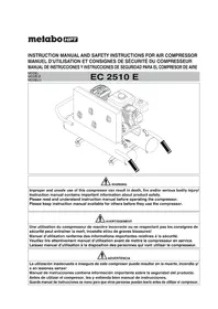
EC2510E - Compressor HiKOKI - Free user manual and instructions
Find the device manual for free EC2510E HiKOKI in PDF.


| Product type | Gas compressor |
| Brand | HiKOKI (metabo HPT) |
| Model | EC2510E |
| Engine | Honda GX160, 4 kW (5.5 hp) at 4000 min⁻¹ |
| Displacement | 163 cm³ |
| Air tank capacity | 30.3 L (8.0 US gal) |
| Maximum pressure | 10.0 bar (145 PSI) |
| Air flow at 40 PSI (2.8 bar) | 309 L/min (10.9 CFM) |
| Air flow at 90 PSI (6.2 bar) | 263 L/min (9.3 CFM) |
| Air flow at 100 PSI (6.9 bar) | 255 L/min (9.0 CFM) |
| Fuel tank capacity | 3.6 L (0.95 US gal) |
| Recommended fuel | Unleaded gasoline, minimum octane rating 85 |
| Engine oil | See Honda GX160 engine manual |
| Pump oil | SAE 15W40 (summer) or SAE 5W50 synthetic (all season) |
| Weight | Approximately 63.5 kg (140 lbs) |
| Dimensions (L × W × H) | Not specified in the manual |
| Power source | Gasoline engine (manual start) |
| Main functions | Compressed air supply for pneumatic tools (nailers, staplers) |
| Maintenance | Pump oil change every 200 h or 3 months, daily tank drain, air filter cleaning |
| Safety | Safety valve, guards for moving parts, engine shutdown before maintenance |
| Spare parts | Use only genuine metabo HPT parts |
| Reparability | Repairs by metabo HPT authorized service center |
Frequently Asked Questions - EC2510E HiKOKI
User questions about EC2510E HiKOKI
0 question about this device. Answer the ones you know or ask your own.
Ask a new question about this device
Download the instructions for your Compressor in PDF format for free! Find your manual EC2510E - HiKOKI and take your electronic device back in hand. On this page are published all the documents necessary for the use of your device. EC2510E by HiKOKI.
USER MANUAL EC2510E HiKOKI
natural_image
Technical line drawing of an industrial air compressor unit with cooling fans and valves (no text or labels)
WARNING
Improper and unsafe use of this compressor can result in death, fire and/or serious bodily injury!
Instruction manual contains important information about product safety.
Please read and understand instruction manual before operating the compressor.
Please keep instruction manual available for others before they use the compressor.

AVERTISSEMENT
MEANINGS OF SIGNAL WORDS....3
SAFETY
IMPORTANT SAFETY INSTRUCTIONS FOR USE OF THE COMPRESSOR.... 4
REPLACEMENT PARTS 5
SERVICE AND REPAIRS 9
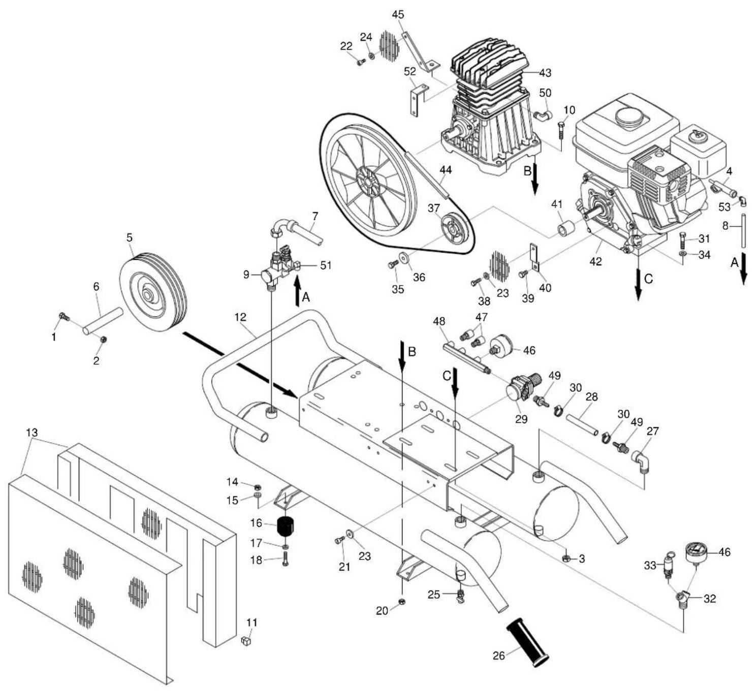
PARTS LIST 28
TABLE DES MATIÈRES
Français
Page
INFORMATIONS IMPORTANTES.... 10
SIGNIFICATION DES SIGNALISATIONS ECRITES ...... 10
SÉCURITÉ
CONSIGNES DE SÉCURITÉ IMPORTANTES POUR L'UTILISATION DU COMPRESSEUR .... 11
PIÈCES DETACHEES 13
UTILISATION ET ENTRETIEN
NOM DES COMPOSANTS 14
SPECIFICATIONS 14
ACCESSOIRES 15
APPLICATION 15
Read and understand all of the operating instructions, safety precautions and warnings in the Instruction Manual before operating or maintaining this compressor.
Most accidents that result from compressor operation and maintenance are caused by the failure to observe basic safety rules or precautions. An accident can often be avoided by recognizing a potentially hazardous situation before it occurs, and by observing appropriate safety procedures.
Basic safety precautions are outlined in the “SAFETY” section of this Instruction Manual and in the sections which contain the operation and maintenance instructions.
Hazards that must be avoided to prevent bodily injury or machine damage are identified by WARNINGS on the compressor and in Instruction Manual.
Never use this compressor in a manner that has not been specifically recommended by metabo HPT, unless you first confirm that the planned use will be safe for you and others.
MEANINGS OF SIGNAL WORDS
WARNING indicates a potentially hazardous situations which, if ignored, could result in serious personal injury.
CAUTION indicates a potentially hazardous situations which, if not avoided, may result in minor or moderate injury, or may cause machine damage.
NOTE emphasizes essential information.

WARNING
The engine exhaust from this product contains chemicals known to the State of California to cause cancer, birth defects or other reproductive harm.
SAFETY
IMPORTANT SAFETY INSTRUCTIONS FOR USE OF THE COMPRESSOR

WARNING: Death or serious bodily injury could result from improper or unsafe use of compressor. To avoid these risks, follow these basic safety instructions:
READ ALL INSTRUCTIONS
Never place your hands, fingers or other body parts near the compressor's moving parts. Never insert your fingers or other objects into the belt guard ventilator. Such an action invites the danger of injuries.
2. NEVER OPERATE WITHOUT ALL GUARDS IN PLACE.
Never operate this compressor without all guards or safety features in place and in proper working order. If maintenance or servicing requires the removal of a guard or safety features, be sure to replace the guard or safety features before resuming operation of the compressor.
3. ALWAYS WEAR PROTECTION.
Risk of injury. Always wear ANSI Z87.1 safety glasses with side shields or equivalent eye protection. Compressed air must never be aimed at anyone or any part of the body. Use ear protection as air flow noise is loud when draining.
4. STOP THE ENGINE.
Always stop the engine and pull out the spark plug cap to prevent any sudden start of the engine and remove the compressed air from the air tank before servicing, inspecting, maintaining, cleaning replacing or checking any parts.
5. STORE COMPRESSOR PROPERLY.
When not in use, the compressor should be stored in indoor dry place. Keep out of reach of children. Lock-out the storage area. Do not store this compressor near an open flame or any equipment such as a stove, furnace, water heater, etc. which utilizes a pilot light or sparking device.
Store flammable materials in a secure location away from compressor.
6. KEEP WORK AREA CLEAN.
Cluttered areas invite injuries. Clear all work areas of unnecessary tools, debris, furniture, etc.
7. CONSIDER WORK AREA ENVIRONMENT.
Don't expose compressor to rain. Don't use compressor in damp or wet locations.
Keep work area well lit and well ventilated. Operate this compressor at a stable place all the time. Risk of fire or explosion. Do not carry and operate the compressor or any other electrical device near the spray area. Do not use compressor in the presence of flammable liquids or gases.
Restricting any of the compressor ventilation openings will cause serious overheating and could cause fire.
Never place objects against or on top of compressor. Gasoline engines produce carbon monoxide; a poisonous odorless gas which may cause death. Do not start or operate this compressor in an enclosed area. Operate compressor in an open area at least 4 feet away from any wall or obstruction that would restrict the flow of fresh air to the ventilation openings.
Compressor produces sparks during operation. Never use compressor in sites containing lacquer, paint, benzine, thinner,
gasoline, gases, adhesive agents, and other materials which are combustible or explosive.
This compressor contains some components parts that tend to produce arcs or sparks, and therefore, when located in a garage, it should be in a room or enclosure provided for this purpose, and should be 18 inches (457 mm) or more above the floor. A spark arrester must be added to the muffler of this engine if it is to be used on any forest covered, brush covered or grass covered unimproved land. The arrester must be maintained in effective working condition by the operator.
In order to avoid damaging this compressor, do not allow the unit to be tilted more than 10^ when operating.
8. KEEP CHILDREN AWAY.
All visitors should be kept safely away from work area.
9. DRESS PROPERLY.
Do not wear loose clothing or jewelry. They can be caught in moving parts. Wear protective hair covering to contain long hair.
10. MAINTAIN COMPRESSOR WITH CARE.
11. STAY ALERT.
Watch what you are doing. Use common sense. Never stand on the compressor. Do not operate compressor when you are tired. Compressor should never be used by you if you are under the influence of alcohol, drugs or medication that makes you drowsy.
12. CHECK DAMAGED PARTS AND AIR LEAK.
Before further use of the compressor, a guard or other part is damaged should be carefully checked to determine that it will operate properly and perform its intended function. Check for alignment of moving parts, binding of moving parts, breakage of parts, mounting, air leak, and any other conditions that may affect its operation. A guard or other part that is damaged should be properly repaired or replaced by an authorized service center unless otherwise indicated elsewhere in this Instruction Manual.
Have defective engine switch replaced by authorized service center. Have defective pilot valve replaced by authorized service center. Do not use compressor if engine switch does not turn it on and off.
13. NEVER USE COMPRESSOR FOR APPLICATIONS OTHER THAN THOSE SPECIFIED.
Never use compressor for applications other than those specified in the Instruction Manual.
Never use compressed air for breathing or respiration.
14. HANDLE COMPRESSOR CORRECTLY.
Operate the compressor according to the instructions provided herein. Never allow the compressor to be operated by children, individuals unfamiliar with its operation or unauthorized personnel.
Carrying the compressor if tilted may result in fuel spillage.
15. KEEP ALL SCREWS, BOLTS AND COVERS TIGHTLY IN PLACE.
Keep all screws, bolts, and covers tightly mounted. Check their conditions periodically.
16. NEVER USE A COMPRESSOR WHICH IS DEFECTIVE OR OPERATING ABNORMALLY.
If the compressor appears to be operating unusually, making strange noises or vibration, or otherwise appears defective, stop using it immediately and arrange for repairs by a metabo HPT authorized service center.
17. DO NOT WIPE PLASTIC PARTS WITH SOLVENT.
Solvents such as thinner, benzene, carbon tetrachloride, and alcohol may damage and crack plastic parts. Do not wipe them with such solvents. Wipe plastic parts with a soft cloth lightly dampened with soapy water and dry thoroughly.
18. USE ONLY GENUINE metabo HPT REPLACEMENT PARTS
Replacement parts not manufactured by metabo HPT may void your warranty and can lead to malfunction and resulting injuries. Genuine metabo HPT parts are available from your dealer.
19. DO NOT MODIFY THE COMPRESSOR.
Do not modify the compressor. Do not operate at pressure or speed in excess of manufacturer's recommendations. Always contact the metabo HPT authorized service center any repairs. Unauthorized modification may not only impair the compressor performance but may also result in accident or injury to repair personnel who do not have the required knowledge and technical expertise to perform the repair operations correctly.
20. TURN OFF THE ENGINE SWITCH WHEN THE COMPRESSOR IS NOT USED
When the compressor is not used, turn off the engine switch and open the drain cock to discharge the compressed air from the air tank.
To reduce the risk of burns, do not touch tubes, heads, cylinder and muffler. Never allow any part of your body or other materials to contact with any exposed metal parts on this compressor. Never allow any part of your body to contact the muffler or adjacent areas. These areas can remain hot for least 45 minutes after this compressor is shutdown. Cool down before servicing.
22. DO NOT DIRECT AIR STREAM AT BODY.
Risk of injury, do not direct air stream at persons or animals, to avoid any bodily injury.
23. DRAIN TANK
Risk of bursting. Water will condense in the air tank. If not drained, water will corrode and weaken the air tank causing a risk of air tank rupture. Drain tank daily or after 4 hours of use. The drain contains moisture in the air, abrasion particles, rust, etc. To drain tank open valve slowly and tilt compressor to empty accumulated water. Keep face and eyes away from drain cock.
24. MAKE SURE THE COMPRESSOR OUTLET PRESSURE IS SET LOWER THAN THE MAXIMUM OPERATING PRESSURE OF THE TOOL.
Too much air pressure causes a hazardous risk of bursting. Check the manufacturer's maximum pressure rating for air tools and accessories. The regulator outlet pressure must never exceed the maximum pressure rating.
25. THE SAFETY VALVE MUST WORK PROPERLY.
Risk of bursting. Before starting the compressor pull the ring on the safety valve to make sure the valve moves freely. If the safety valve does not work properly, over-pressurization may occur, causing air tank rupture or an explosion.
26. USE OF THIS PRODUCT WILL EXPOSE YOU TO CHEMICALS KNOWN TO THE STATE OF CALIFORNIA.
Some dust created by this product contains chemicals known to State of California to cause cancer, birth defects or other reproductive harm. Some examples of these chemicals are:
- compounds in fertilizers
- compounds in insecticides, herbicides and pesticides
- arsenic and chromium from chemically treated lumber
To reduce your exposure to these chemicals, wear approved safety equipment such as dust masks that are specially designed to filter out microscopic particles. Use of this product will expose you to chemicals known to the State of California to cause cancer, birth defects and other reproductive harm. Avoid inhaling vapors and dust, and wash hands after using. This product contains chemicals, including lead, known to the State of California to cause cancer, and birth defects or other reproductive harm. Wash hands after handling.
27. SEE TO IT THAT FUEL IS SUPPLIED APPROPRIATELY.
Follow all fueling instructions in operator's manual.
Gasoline is extremely flammable, and gasoline vapor can explode. Do not refuel tank while this compressor is running or hot. Never smoke near gasoline, and keep other flames and sparks away. Do not refuel indoors or in a poorly ventilated area. Do not fill fuel tank to point of overflowing. Always refuel slowly to avoid the possibility of spilled fuel which may cause a fire. Do not operate this compressor if gasoline is spilled. Wipe this compressor clean and move it away from the spill. Avoid creating any ignition until the gosoline has evaporated. Allow approximately 1/4" of tank space for fuel expansion. Always store fuel away from this compressor while it is running or hot. Always store gasoline in an approved container.
28. BE CAREFUL NOT TO TRIP OVER OR DROP THE COMPRESSOR DURING TRANSPORT.
Exercise utmost caution when you carry this compressor. If you trip over something and drop it, there is a fear that unexpected injury may result. If you drop this compressor or bump it against any objects, air tank or any component parts can cause serious deformation, damage, severe scratches and breakdown on this compressor. If operated under such conditions, it can result in any accidents or bodily injuries by explosion of the air tank or explosion of those damaged component parts. Furthermore, gasoline which spilled out by those damages, may have a great risk of a fire. When there is any deformation and damage on the handle, it may drop during transport, resulting in an accident of injury. Before carrying this compressor, switch off the engine and discharge the drain inside the air tank. Be cautious enough to make sure that there are no obstacles, inflammable articles, and unauthorized people around this compressor.
REPLACEMENT PARTS
When servicing use only identical replacement parts.
Repairs should be conducted only by a metabo HPT authorized service center.
SAVE THESE INSTRUCTIONS AND MAKE THEM AVAILABLE TO OTHER USERS OF THIS TOOL!
The information contained in this Instruction Manual is designed to assist you in the safe operation and maintenance of the compressor.
Some illustrations in Instruction Manual may show details or attachments that differ from those on your own compressor.
SPECIFICATIONS
| Compressor Model EC 2510 E | ||
| Engine Manufacturer and Model Honda | GX160 | |
| Displacement 9.9 cu in (163cm) | 3) | |
| Max. output 4kW (5.5hp) / Fuel Tank Capacity 0.95 US gal (3.6 ltr) | -1 | |
| Tank Capacity 8.0 US gal (30.3 ltr) | ||
| Maximum Pressure 145 PSI (10.0 bar) | ||
| Free Air Delivery at 40 PSI 10.9 CFM | (309 ltr/min)(2.8 bar) | |
| at 90 PSI 9.3 CFM (263 ltr/min)(6.2 bar) | ||
| at 100 PSI 9.0 CFM (255 ltr/min)(6.9 bar) | ||
ACCESSORY

WARNING: Accessory other than these shown below can lead to malfunction and resulting injuries.
STANDARD ACCESSORY
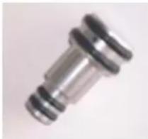
Breather pipe plug .... 1
natural_image
Close-up of a metallic mechanical component with threaded ends (no visible text or symbols)APPLICATIONS
Air source of the pneumatic nailer and stapler.

WARNING: Never use compressor for applications other than compressor for pneumatic nailer and stapler.
PRIOR TO OPERATION
1. Initial set-up
A) Read safety warnings before setting-up this compressor.
B) Use a screwdriver or similar tool to remove the cap on the lower part of the cylinder. Insert the accessory Breather pipe plug all the way to the bottom.
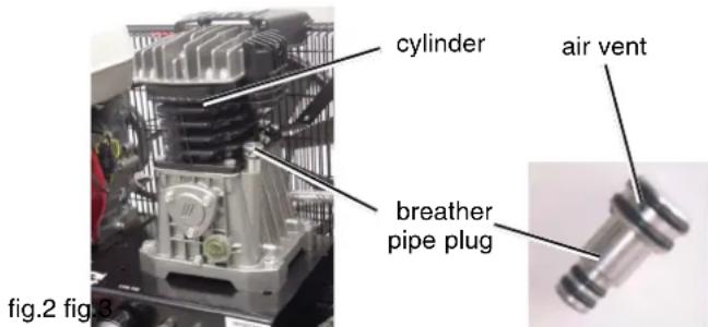

WARNING: Drain tank to release air pressure before removing the breather pipe plug.

WARNING: Make sure air vent in breather pipe plug is free from debris. If air vent is blocked pressure can build in crankcase causing damage to compressor and possible personal injury.
Ensure the oil level in this compressor pump is adequate. If the oil level is low, replenish oil through the filling hole so that the amount of oil will come to the middle of the oil sight glass according to the following OIL TYPE CHART.
OIL TYPE CHART
| Ambient 50~120 -20~120 temperature (°F) (°F) | (°F) | |
| Non-detergent oil | SAE15W40 graded oil for warm winter use only | SAE5W50 synthetic oil for both summer and winter use |
2. Location

WARNING: In order to avoid damaging this compressor, do not incline this compressor transversally or longitudinally more than 10^ .
Place this compressor at least 4 inches away from obstacles that may prevent proper ventilation. Do not place this
compressor in an area:
- where there is evidence of oil or gas leaks.
- where flammable gas vapors or materials may be present.
- where air temperatures fall below 32^ F or exceed 95^ F.
- where extremely dirty air or water could be drawn into this compressor.
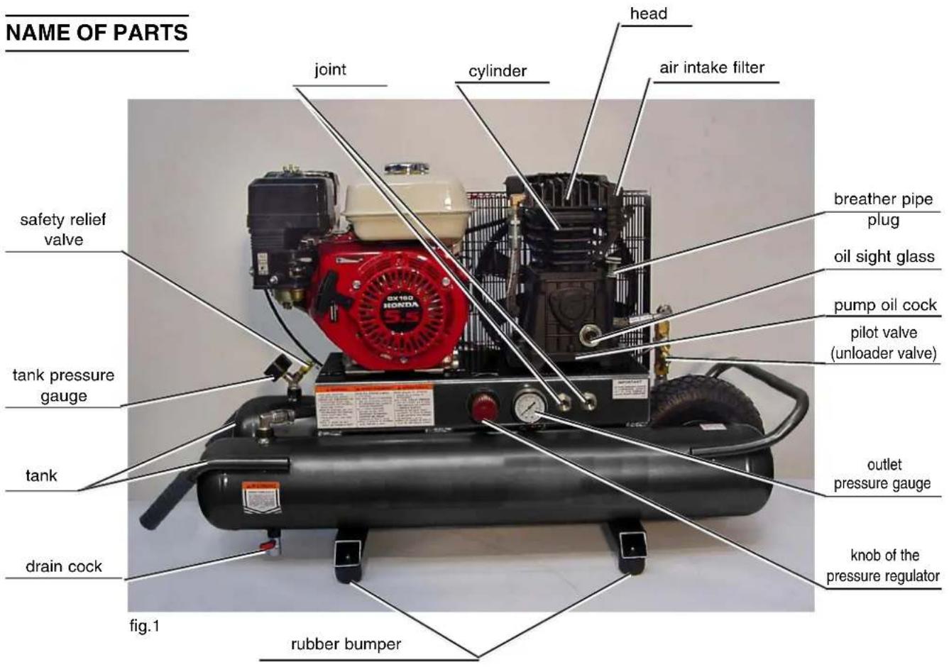
NOTE: When operating or storing the compressor, set 4 rubber bumpers downward on the floor (Refer to fig. 1).
3. Gasoline engine
A) Review page 5.27 before fueling.

WARNING: Do not allow the engine or muffler to come in contact with flammable vapors, combustible dust, gases or other combustible materials. A spark may cause a fire. Do not place this compressor in an area where flammable gas vapors may be present.
B) Read the engine manual accompanying this compressor for correct engine start-up maintenance procedures.
C) Read and understand the safety labels located on this compressor.
D) A minimum of 85 octane fuel is recommended for use with this compressor. Do not mix oil with gasoline.
E) Use of clean, fresh, lead free gasoline should be used. Do not use gasoline containing methanol or alcohol.
F) Check the engine oil level before starting (See engine manual).
G) Fill the fuel tank according to the engine manual instructions.

WARNING: Follow all fueling instructions in operator's manual. Gasoline is extremely flammable, and gasoline vapor can explode. Do not refuel fuel tank while this compressor is running or hot. Never smoke near gasoline, and keep other flames and sparks away. Allow this compressor and engine to cool down before refueling. Do not refuel indoors or in a poorly ventilated area. Do not fill fuel tank to point of overflowing. Always refuel slowly to avoid the possibility of spilled fuel which may cause a fire. Do not operate this compressor if gasoline is spilled. Wipe this compressor clean and move it away from the spill. Avoid creating any ignition until the gasoline has evaporated. Allow approximately 1/4" of tank space for fuel expansion. Always store fuel away from this compressor while it is running or hot. Always store gasoline in an approved container.
H) Refer to the engine manual for all necessary maintenance and adjustments.

WARNING: Do not operate this compressor in an enclosed area. Use this compressor only in well ventilated areas. The exhaust from the engine contains carbon monoxide, a poisonous, odorless and invisible gas. Breathing the gas can cause serious injury, illness and possible death. Avoid inhalation of exhaust gas. Never run the engine in a closed garage or confined area.
4. Air coupler installation
Screw in the air coupler to the joint (Refer to fig.1 and fig.5). The screw size of the joint is 3/8". Use an air coupler which has the same screw size.
5. Pre-start checklist
A) Oil level should be checked on a daily basis to ensure it does not exceed the maximum notch or does not fall below
the minimum notch on the oil sight glass. If the oil level is low, replenish oil through the filling hole so that the amount of oil will come to a point between the maximum notch and the minimum notch of the oil sight glass according to the OIL TYPE CHART on page 7.

CAUTION: Overfilling with oil will cause premature compressor failure. Do not overfill.
B) Remove any moisture in this compressor air tank. Gradually open the drain cock and discharge the drain. Close tightly when drained.
C) Make sure the engine switch is in the "OFF" position.
D) Make sure the safety relief valve is working correctly (Refer to fig.1). The safety relief valve is designed to prevent system failures by relieving pressure from the system when this compressed air reaches a predetermined level. The safety relief valve is preset by the manufacturer and must not be modified in any way. To verify the safety relief valve is working properly, pull on the ring. Air pressure should escape. When the ring is released, it will reset.
E) Make sure all guards and covers are in place and securely mounted.
TRANSPORT
Turn off the engine switch before move the compressor. Transport the compressor in the correct manner.

WARNING: Unit weighs more than 140 lbs(63.5kg). Do not move or lift without assistance.

WARNING: Ensure proper footing and use caution when rolling compressor so that unit does not tip or cause loss of balance.
NOTE: Use the handle to lift or carry the unit.
OPERATION
1. Start-up
A) Read safety warnings before performing operation.
B) When the toggle is in the upright position, all air from this compressor is vented through the discharge muffler (fig.4). This gives an easy start feature. For normal operation, the toggle is in the 90^ position.
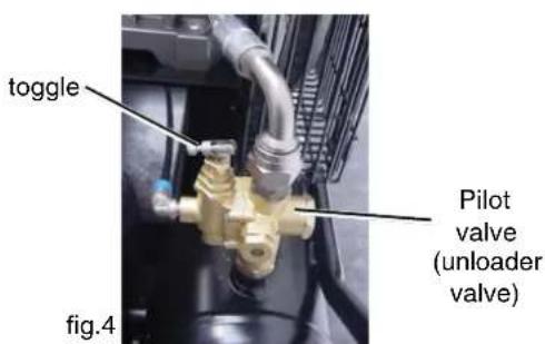
C) Start engine (Refer to the Engine Manual accompanying this unit).
D) When the engine has run for 1-2 minutes, flip toggle back to the original position.
The operation of this compressor is automatic and is controlled by the pilot valve which idles it when the pressure in the air-tank reaches the maximum level and restarts it when the air pressure drops during use to the restart level. The pilot valve is preset by the manufacturer and must not be modified in any way.

WARNING: If you notice any unusual noise or vibration, stop this compressor.

CAUTION: Wear appropriate personal hearing protection during use. Under some conditions and duration of use, noise from this product may contribute to hearing loss.
2. Adjustment of working pressure
The air pressure coming from the air tank is controlled by the regulator knob (fig.5). Turn the pressure regulation knob clockwise to increase discharge pressure, and counterclockwise to decrease discharge pressure.
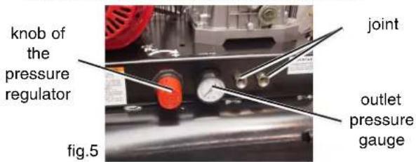
The outlet pressure gauge indicates the air pressure available at the outlet side of the regulator. This pressure is controlled by the regulator and is always less or equal to the air tank pressure. The air tank pressure gauge indicates the reserve air pressure in the air tank(s). When adjusting the pressure, check and make sure that a pressure gauge for the tank has the pressure level that is higher than that of the pressure to be adjusted. It is also imperative that you make adjustment by slowly starting up the pressure from the level that is lower than the pressure to be adjusted.

WARNING: Check the manufacturer's maximum pressure rating for nailers, staplers and accessories. Compressor outlet pressure must be regulated so as to never exceed the maximum pressure rating of the nailers, staplers and accessories.
3. Shutdown
A) To stop this compressor, move the engine switch to the "Off" position (Refer to the Engine Manual accompanying this unit).
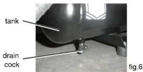
B) Gradually open the drain cock, take out the drainage and all the compressed air inside the tank to prevent any internal corrosion of the tank (fig.6).

WARNING: Risk of bursting. When the tank gets corroded, there is a risk of breakdown. Water will condense in the air tank. If not drained, water will corrode and weaken the air tank causing a risk of air tank rupture. Drain tank daily or after 4 hours of use. The drain contains moisture in the air, abrasion particles, rust, etc. To drain tank open valve slowly and tilt compressor to empty accumulated water. Keep face and eyes away from drain cock.
C) Allow the compressor to cool down.
D) Wipe this compressor clean and store in a safe, nonfreezing area.
MAINTENANCE

WARNING: Remove the compressed air from the air tank before performing the maintenance operations. Allow the compressor to cool before performing the maintenance operations. Always stop engine and pull out the spark plug cap to prevent any sudden start of the engine and remove this compressed air from the air tank before performing the maintenance operations.
Read the instruction manual before performing maintenance. The following procedures must be performed when stopping the compressor for maintenance or service.
A) Turn off the compressor.
B) Disconnect spark plug wire from engine.
C) Open all drains.
D) Wait for this compressor to cool down before starting service.
- Cleaning the air intake filter
This filter is designed to clean air coming into the pump (fig.7). To ensure the pump continually receives clean, cool, dry air supply this filter must always be clean and ventilation opening must always be free from obstructions.

WARNING: Never clean filtering element with a flammable liquid or solvent.

CAUTION: Do not operate without the intake filter.
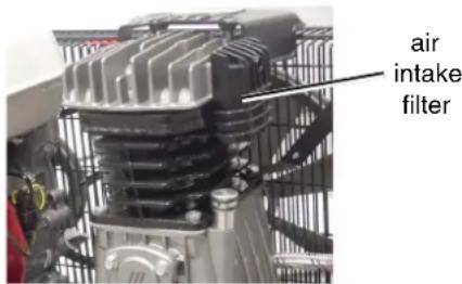
fig.7
NOTE: Replace the filter element when it becomes dirty.
- Draining tank:
Gradually open the drain valve, and drain out the air in the tank. Close tightly when drained.
- Oil change-oil topping off.
- Maintenance chart:
MAINTENANCE CHART
| PROCEDURE | AFTER USE | DAILY | WEEKLY | MONTHLY | 200 HOURS |
| Check pump oil level X | |||||
| Oil leak inspection X | |||||
| Drain condensation in air tank(s) X | X | ||||
| Inspect guards/covers | X | ||||
| Check for unusual noise/vibration | X | ||||
| Check for air leaks | X | ||||
| Clean exterior of compressor | X | ||||
| Inspect air filter | X | ||||
| Check safety relief valve | X | ||||
| Inspect belt tension | X | ||||
| Change pump oil | X | ||||
| Replace air filter | X |
The pump oil must be changed after the first 50 hours of operation and every 200 hours or 3 months, whichever comes first. Open the pump oil cock and replace pump oil. As regards the engine, follow instructions in the engine manual. Every 2 years, an Authorized Service Technician should check the check valve, intake valves and delivery valves.
SERVICE AND REPAIRS
All quality compressors will eventually require servicing or replacement of parts because of wear and tear from normal use. To assure that only authorized/genuine replacement parts will be used, all service and repairs must be performed by a metabo HPT AUTHORIZED SERVICE CENTER, only.
NOTE: Specifications are subject to change without any obligation on the part of the metabo HPT.
INFORMATIONS IMPORTANTES
natural_image
Close-up of a metallic mechanical component with threaded ends (no visible text or symbols)APPLICATION
natural_image
Close-up of a metallic mechanical component with threaded ends (no visible text or symbols)APLICACIONES
Parts are subject to change without any obligation on the part of metabo HPT due to improvements.
Feb. 2007
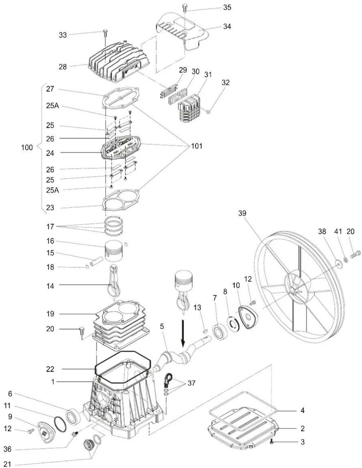
AB 360 PUMP UNIT
| ITEM CODE PART NAME Q.TY REFERENCENO. NO. NO. | ||||
| 1 8854 | 52 CRANKCASE | 1 9700000259 | ||
| 2 8854 | 53 CRANKCASE | COVER 1 9100270120 | ||
| 3 1605 | 73 SCREW M5x1 | 6 UNI7687 4 4084620000 | ||
| 4 8854 | 54 OR GASKET | 1 9100270130 | ||
| 5 8854 | 55 CRANKSHAFT | 1 9100270140 | ||
| 6 8854 | 56 BEARING 6203 | 1 706018 | 0000 | |
| 7 8816 | 22 BEARING 6204 | 1 706020 | 0000 | |
| 8 8854 | 57 OIL SEAL 20x47x7 | 1 910027 | 0150 | |
| 9 8854 | 58 FRONT COVER | 1 970000 | 0261 | |
| 10 8854 | 459 REAR COVER | 1 970000 | 0262 | |
| 11 8854 | 460 OR 144 GASKET | 1 91002 | 80010 | |
| 12 8816 | 657 SCREW | 6 40841 | 70000 | |
| 13 8854 | 461 KEY | 1 91002 | 80020 | |
| 14 8854 | 462 CONNECTING ROD | 2 91002 | 70010 | |
| 15 8854 | 463 PISTON PIN | 2 91002 | 70020 | |
| 16 8854 | 464 PISTON | 2 91002 | 70030 | |
| 17 8854 | 465 PISTON RINGS KIT | 2 40801 | 20000 | |
| 18 8854 | 468 SEEGER | 4 91002 | 70070 | |
| 19 8854 | 469 CYLINDER | 1 91002 | 70080 | |
| 20 8816 | 571 SCREW | 4 40841 | 100000 | |
| 21 8854 | 470 OIL LEVEL SIGHT GLASS | 1 | 9700000408 | |
| 22 8854 | 471 OR GASKET | 1 9100270180 | ||
| 23 | GASKET | 1 1129 | 100502 | |
| 24 | VALVE PLATE | 1 1127 | 450999 | |
| 25 | VALVE | 1 1127 | 190822 | |
| 26 | VALVE | 4 1127 | 190821 | |
| 27 8854 | 476 GASKET | 1 91002 | 70210 | |
| 28 8854 | 477 HEAD | 1 97000 | 00263 | |
| 29 8816 | 453 FILTER PLATE | 1 74583 | 40000 | |
| 30 8816 | 553 FILTERING ELEMENT | 1 72100 | 10000 | |
| 31 8854 | 480 INTAKE FILTER | 1 91002 | 70240 | |
| 32 8816 | 412 SCREW | 1 40842 | 40000 | |
| 33 8854 | 481 SCREW M8x35 UNI5931 6 4084030000 | |||
| 34 8854 | 482 AIR CONVEYOR | 1 91002 | 70220 | |
| 35 8816 | 479 SCREW | 2 40842 | 70000 | |
| 36 8816 | 657 SCREW | 1 40841 | 70000 | |
| 37 8854 | 483 BREATHER PIPE PLUG | 1 40823 | 70000 | |
| 38 8816 | 663 WASHER | 1 40845 | 10000 | |
| 39 8854 | 484 FLYWHEEL | 1 97000 | 00264 | |
| 40 8816 | 571 SCREW | 1 40841 | 100000 | |
| 41 8816 | 578 TOOTHED WASHER | 1 40845 | 30000 | |
| 100 | SET VALVE PLATE | 1 1129 | 703272 | |
| 101 | 160572 KIT GASKETS | 1 9700000078 | ||
Parts are subject to change without any obligation on the part of HITACHI due to improvements.
June 2018
AB360-PUMP UNIT
Issued by
Koki Holdings Co., Ltd.
Shinagawa Intercity Tower A, 15-1, Konan 2-chome,
Minato-ku, Tokyo 108-6020, Japan
Distributed by
Koki Holdings America Ltd.
1111 Broadway Ave,
Braselton, Georgia, 30517
Koki Holdings America Ltd. Canadian Branch
3405 American Drive, Units 9-10,
Mississauga, ON, L4V 1T6
- WARNING
- AVERTISSEMENT
- SAFETY
- TABLE DES MATIÈRES
- Français
- SÉCURITÉ
- UTILISATION ET ENTRETIEN
- MEANINGS OF SIGNAL WORDS
- IMPORTANT SAFETY INSTRUCTIONS FOR USE OF THE COMPRESSOR
- READ ALL INSTRUCTIONS
- NEVER OPERATE WITHOUT ALL GUARDS IN PLACE.
- ALWAYS WEAR PROTECTION.
- STOP THE ENGINE.
- STORE COMPRESSOR PROPERLY.
- KEEP WORK AREA CLEAN.
- CONSIDER WORK AREA ENVIRONMENT.
- KEEP CHILDREN AWAY.
- DRESS PROPERLY.
- MAINTAIN COMPRESSOR WITH CARE.
- STAY ALERT.
- CHECK DAMAGED PARTS AND AIR LEAK.
- NEVER USE COMPRESSOR FOR APPLICATIONS OTHER THAN THOSE SPECIFIED.
- HANDLE COMPRESSOR CORRECTLY.
- KEEP ALL SCREWS, BOLTS AND COVERS TIGHTLY IN PLACE.
- NEVER USE A COMPRESSOR WHICH IS DEFECTIVE OR OPERATING ABNORMALLY.
- DO NOT WIPE PLASTIC PARTS WITH SOLVENT.
- USE ONLY GENUINE metabo HPT REPLACEMENT PARTS
- DO NOT MODIFY THE COMPRESSOR.
- TURN OFF THE ENGINE SWITCH WHEN THE COMPRESSOR IS NOT USED
- DO NOT DIRECT AIR STREAM AT BODY.
- DRAIN TANK
- MAKE SURE THE COMPRESSOR OUTLET PRESSURE IS SET LOWER THAN THE MAXIMUM OPERATING PRESSURE OF THE TOOL.
- THE SAFETY VALVE MUST WORK PROPERLY.
- USE OF THIS PRODUCT WILL EXPOSE YOU TO CHEMICALS KNOWN TO THE STATE OF CALIFORNIA.
- SEE TO IT THAT FUEL IS SUPPLIED APPROPRIATELY.
- BE CAREFUL NOT TO TRIP OVER OR DROP THE COMPRESSOR DURING TRANSPORT.
- REPLACEMENT PARTS
- SAVE THESE INSTRUCTIONS AND MAKE THEM AVAILABLE TO OTHER USERS OF THIS TOOL!
- ACCESSORY
- STANDARD ACCESSORY
- APPLICATIONS
- PRIOR TO OPERATION
- Initial set-up
- Location
- Gasoline engine
- Air coupler installation
- Pre-start checklist
- CAUTION: Overfilling with oil will cause premature compressor failure. Do not overfill.
- TRANSPORT
- WARNING: Unit weighs more than 140 lbs(63.5kg). Do not move or lift without assistance.
- WARNING: Ensure proper footing and use caution when rolling compressor so that unit does not tip or cause loss of balance.
- OPERATION
- Start-up
- WARNING: If you notice any unusual noise or vibration, stop this compressor.
- CAUTION: Wear appropriate personal hearing protection during use. Under some conditions and duration of use, noise from this product may contribute to hearing loss.
- Adjustment of working pressure
- WARNING: Check the manufacturer's maximum pressure rating for nailers, staplers and accessories. Compressor outlet pressure must be regulated so as to never exceed the maximum pressure rating of the nailers, staplers and accessories.
- Shutdown
- WARNING: Risk of bursting. When the tank gets corroded, there is a risk of breakdown. Water will condense in the air tank. If not drained, water will corrode and weaken the air tank causing a risk of air tank rupture. Drain tank daily or after 4 hours of use. The drain contains moisture in the air, abrasion particles, rust, etc. To drain tank open valve slowly and tilt compressor to empty accumulated water. Keep face and eyes away from drain cock.
- MAINTENANCE
- SERVICE AND REPAIRS
- INFORMATIONS IMPORTANTES
- APPLICATION
- APLICACIONES
- AB360-PUMP UNIT
- Koki Holdings Co., Ltd.
- Koki Holdings America Ltd.
- Koki Holdings America Ltd. Canadian Branch
Brand : HiKOKI
Model : EC2510E
Category : Compressor