
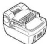
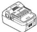
WH14DBAL2 - Screwdriver HiKOKI - Free user manual and instructions
Find the device manual for free WH14DBAL2 HiKOKI in PDF.

| Product type | Cordless impact driver |
| Brand | HiKOKI |
| Model | WH14DBAL2 |
| Rated voltage | 14.4 V |
| No-load speed (high mode) | 0 – 2800 min⁻¹ |
| No-load speed (medium mode) | 0 – 2200 min⁻¹ |
| No-load speed (low 2 mode) | 0 – 1500 min⁻¹ |
| No-load speed (low 1 mode) | 0 – 900 min⁻¹ |
| Tightening capacity (ordinary bolts) | M5 – M14 |
| Tightening capacity (high-strength bolts) | M5 – M12 |
| Maximum tightening torque | 160 N·m |
| Battery type | Li-ion 14.4 V |
| Battery capacity (standard) | 3.0 Ah (BSL1430) / 4.0 Ah (BSL1440) |
| Compatible charger | UC18YRSL (14.4 – 18 V) |
| Weight (with battery) | 1.4 kg |
| Protection rating | IP56 (dust and water jet resistance) |
| Main functions | 4-speed electronic speed control, LED lighting, battery charge indicator, on/off function, reversible rotation direction, belt hook |
| Maintenance and cleaning | Clean with a dry or slightly damp cloth (soapy water). Do not use solvents. Store at a temperature below 40 °C out of reach of children. |
| Safety | Protection against overload, deep discharge, and overheating (automatic shutdown). Use only genuine HiKOKI batteries. Wear hearing and eye protection. |
| Spare parts and repairability | Use only HiKOKI spare parts. Have any repairs carried out by an authorized HiKOKI service center. |
| Warranty | Warranty in accordance with national regulations. Does not cover normal wear and tear or damage due to misuse. |
Frequently Asked Questions - WH14DBAL2 HiKOKI
User questions about WH14DBAL2 HiKOKI
0 question about this device. Answer the ones you know or ask your own.
Ask a new question about this device
Download the instructions for your Screwdriver in PDF format for free! Find your manual WH14DBAL2 - HiKOKI and take your electronic device back in hand. On this page are published all the documents necessary for the use of your device. WH14DBAL2 by HiKOKI.
USER MANUAL WH14DBAL2 HiKOKI
natural_image
Line drawing of a handheld electric drill press device with attached cable (no text or symbols)
natural_image
Line drawing of a handheld electric drill press device with handle and control panel (no text or symbols)WH18DBAL2 WR18DBAL2
Read through carefully and understand these instructions before use. Diese Anleitung vor Benutzung des Werkzeugs sorgfältig durchlesen und verstehen. Lire soigneusement et bien assimiler ces instructions avant usage. Prima dell'uso leggere attentamente e comprendere queste istruzioni. Deze gebruiksaanwijzing s.v.p. voor gebruik zorgvuldig doorlezen. Leer cuidadosamente y comprender estas instrucciones antes del uso. Antes de usar, leia com cuidado para assimilar estas instruções.
Handling instructions Bedienungsanleitung Mode d'emploi Istruzioni per l'uso Gebruiksaanwijzing Instrucciones de manejo Instruções de uso
1
2
3
4
11
5
6
7
8
109
11
12
| English Deutsch Français Italiano | ||||
| 1 | Rechargeable battery | Akkumulator | Batterie rechargeable | Batteria ricaricabile |
| 2 | Latch | Schnapper | Loquet | Fermo |
| 3 | Battery cover | Batterieabdeckung | Couvercle de batterie | Coperchio per la batteria |
| 4 | Terminals | Anschlüsse | Bornes | Terminali |
| 5 | Ventilation holes | Belüftungslöcher | Orifices de ventilation | Fori di ventilazione |
| 6 | Push | Drücken | Pousser | Spingere |
| 7 | Pull out | Herausziehen | Tirer | Estrarre |
| 8 | Handle | Griff | Poignée | Impugnatura |
| 9 | Pilot lamp | Kontrollampe | Lampe témoin | Spia |
| 10 | Line | Leitung | Ligne | Linea |
| 11 | After insert | Nach dem Einsetzen | Après insertion | Dopo l'inserimento |
| 12 | Driver bit | Dreherspitze | Mèche | Testa avvitatrice |
| 13 | Movement | Bewegung | Mouvement | Movimento |
| 14 | Guide sleeve | Führungsmanschette | Manchon-guide | Manicotto guida |
| 15 | Hexagonal hole in the anvil | Sechskantloch in der Schabotte | Orifice hexagonal de la chabotte | Foro esagonale nel basamento |
| 16 | Hexagonal socket | Sechskantbuchse | Douille hexagonal | Chiave de incavo esagonale |
| 17 | Groove | Schlitz | Rainure | Scanalature |
| 18 | Anvil | Schabotte | Chabotte | Basamento |
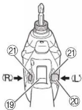
| 19 | Trigger switch | Trigger | Déclencheur | Interruttore |
| 20 | Selector button | Wählhebel | Sélecteur | Selettore |
| 21 | (R) and (L) marks | (R) und (L) Zeichen | Indices (R) et (L) | Segno (R), (L) |
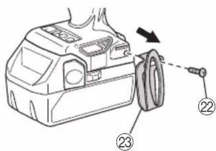
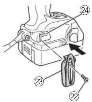
| 22 | Screw | Schraube | Vis | Vite |
| 23 | Hook | Haken | Crochet | Gancio |
| 24 | Groove | Nut | Gorge | Scanalatura |
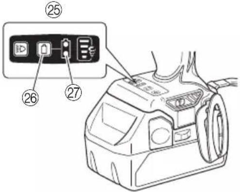
| 25 | Switch panel | Schalttafel | Tableau de commande | Pannello dell'interruttore |
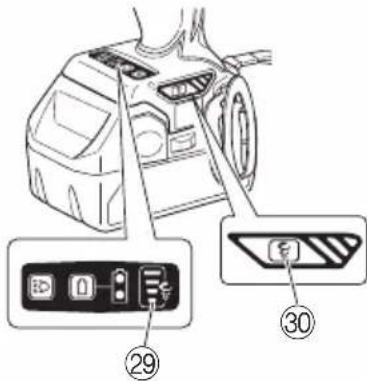
| 26 | Remaining battery indicator switch | Ladezustand-Anzeigeschalter | Commutateur de puissance batterie résiduelle | Interruttore indicatore batteria restante |
| 27 | Remaining battery indicator lamp | Ladezustand-Kontrollleuchte | Témoin lumineux de puissance batterie résiduelle | Spia luminosa batteria restante |
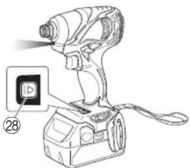
| 28 | Light switch | Lichtschalter | Commutateur d'éclairage | Interruttore della luce |
| 29 | High/Low indicator lamp | Stark/Schwach-Anzeigeleuchte | Voyant indicateur haut/bas | Spia indicatore Alto/Basso |
| 30 | High/Low selector switch | Stark/Schwach-Wahlschalter | Sélecteur Haut/Bas | Interruttore selettore Alto/Basso |
| Nederlands Español | Português | ||
| 1 | Oplaadbare batterij | Batería recargable | Bateria de recarregável |
| 2 | Vergrendeling | Enganche | Lingüeta |
| 3 | Batterijdeksel | Tapa de batería | Tampa da bateria |
| 4 | Aansluitpunten | Terminales | Terminais |
| 5 | Ventilatieopeningen | Orificios de ventilación | Orifícios de ventilação |
| 6 | Drukken | Presionar | Apertar |
| 7 | Uittrekken | Sacar | Retirar |
| 8 | Handgreep | Mango | Cabo |
| 9 | Controlelampje | Lámpara piloto | Lâmpada piloto |
| 10 | Lijn | Línea | Linha |
| 11 | Na insteken | Tras la introducción | Depois de inserir |
| 12 | Schroefstuk | Punta de destornillador | Chave de fenda |
| 13 | Beweging | Movimiento | Movimento |
| 14 | Geleide ring | Manguito guía | Manga-guia |
| 15 | Zeshoekige opening in het draaistuk | Orificio hexagonal en el yunque | Orifício sextavado na bigorna |
| 16 | Zeschoekige bus | Recaptáculo hexanogal | Encaixe longo |
| 17 | Groef | Ranura | Ranhura |
| 18 | Draaistuk | Yunque | Bigorna |
| 19 | Trekkerschakelaar | Conmutador de gatillo | Interruptor de comando |
| 20 | Omzetschakelaar | Botón selector | Botão seletor |
| 21 | (R) en (L) merktekens | Marcas(R) y (L) | Marcas (R) e (L) |
| 22 | Schroef | Tornillo | Parafuso |
| 23 | Haak | Gancho | Gancho |
| 24 | Groef | Ranura | Ranhura |
| 25 | Schakelaarpaneel | Panel de interruptores | Painel de interruptores |
| 26 | Indicatieschakelaar resterende acculading | Interruptor de indicador de batería restante | Interruptor de indicação da autonomia da pilha |
| 27 | Indicatielampje resterende acculading | Indicador luminoso batería restante | Luz de indicação da autonomia da pilha |
| 28 | Lichtschakelaar | Interruptor de luces | Interruptor da luz |
| 29 | Hoog/laag indicatorlampje | Lámpara indicadora alta/baja | Luz indicadora de alto/baixo |
| 30 | Hoog/laag keuzeschakelaar | Interruptor selector alto/bajo | Interruptor de selecção alto/baixo |
| Symbols⚠ WARNINGThe following show symbols used for the machine. Be sure that you understand their meaning before use. | Symbole⚠ WARNUNGDie folgenden Symbole werden für diese Maschine verwendet. Achten Sie darauf, diese vor der Verwendung zu verstehen. | Symboles⚠ AVERTISSEMENTLes symboles suivants sont utilisés pour l’outil. Bien se familiariser avec leur signification avant d’utiliser l’outil. | Simboli⚠ AVVERTENZADi seguito mostriamo i simboli usati per la macchina. Assicurarsi di comprenderne il significato prima dell’uso. | |
 | Read all safety warnings and all instructions.Failure to follow the warnings and instructions may result in electric shock, fire and/or serious injury. | Lesen Sie sämtliche Sicherheitshinweise und Anweisungen durch.Wenn die Warnungen und Anweisungen nicht befolgt werden, kann es zu Stromschlag, Brand und/oder ernsthaftenVerletzungen kommen. | Lire tous les avertissements de sécurité et toutes les instructions.Tout manquement à observer ces avertissements et instructions peut engendrer des chocs électriques, des incendies et/ou des blessures graves. | Les[ere tutti gli avvertimenti di sicurezza e tutte le istruzioni.La mancata osservanza degli avvertimenti e delle istruzioni potrebbe essere causa di scosse elettriche, incendi e/o gravi lesioni. |
 | Only for EU countriesDo not dispose of electric tools together with household waste material!In observance of European Directive 2002/96/EC on waste electrical and electronic equipment and its implementation in accordance with national law, electric tools that have reached the end of their life must be collected separately and returned to an environmentally compatible recycling facility. | Nur für EU-Länder Werfen Sie Elektrowerkzeuge nicht in den Hausmüll!Gemäss Europäischer Richtlinie 2002/96/EG über Elektro- und Elektronik-Altgeräte und Umsetzung in nationales Recht müssen verbrauchte Elektrowerkzeuge getrennt gesammelt und einer umweltgerechtenWiederververitung zugeführt werden. | Pour les pays européens uniquementNe pas jeter les appareils électriques dans les ordures ménagères!Conformément à la directive européenne 2002/96/CE relative aux déchets d’équipements électriques ou électroniques (DEEE), et à sa transposition dans la législation nationale, les appareils électriques doivent être collectés à part et être soumis à un recyclage respectueux de l’environnement. | Solo per Paesi UENon gettare le apparecchiature elettriche tra i rifiuti domestici.Secondo la Direttiva Europea 2002/96/CE sui rifiuti di apparecchiature elettriche ed elettroniche e la sua attuazione in conformità alle norme nazionali, le apparecchiature elettriche esauste devono essere raccolte separatamente, al fine di essere reimpiegate in modo eco-compatibile. |
| Symbolen⚠ WAARSCHUWINGHieronder staan symbolen afgebeeld die van toepassing zijn op deze machine. U moet de betekenis hiervan begrijpen voor gebruik. | Símbolos⚠ ADVERTENCIAA continuación se muestran los símbolos usados para la máquina. Asegúrese de comprender su significado antes del uso. | Símbolos⚠ AVISOA seguir aparecem os símbolos utilizados pela máquina. Assimile bem seus significados antes do uso. | ||
 | Lees alle waarschuwingen en instructies aandachtig door.Nalating om de waarschuwingen en instructies op te volgen kan in een elektrische schok, brand en/of ernstig letsel resulteren. | Lea todas las instrucciones y advertencias de seguridad.Si no se siguen las advertencias e instrucciones, podría producirse una descarga eléctrica, un incendio y/o daños graves. | Leia todas as instruções e avisos de segurança.Se não seguir todas as instruções e os avisos, pode provocar um choque eléctrico, incêndio e/ou ferimentos graves. | |
 | Alleen voor EU-landen Geef elektrisch gereedschap niet met het huisvuil mee!Volgens de Europese richtlijn 2002/96/EC inzake oude elektrische en elektronische apparaten en de toepassing daarvan binnen de nationale wetgeving, dient gebruikt elektrisch gereedschap gescheiden te worden ingezameld en te worden afgevoerd naar een recycle bedrijf dat voldoet aan de geldende milieu-eisen. | Sólo para países de la Unión Europea¡No deseche los aparatos eléctricos junto con los residuos domésticos!De conformidad con la Directiva Europea 2002/96/CE sobre residuos de aparatos eléctricos y electrónicos y su aplicación de acuerdo con la legislación nacional, las herramientas eléctricas cuya vida útil haya llegado a su fin se deberán recoger por separado y trasladar a una planta de reciclaje que cumpla con las exigencias ecológicas. | Apenas para países da UENão deite ferramentas eléctricas no lixo doméstico!De acordo com a directiva europeia 2002/96/CE sobre ferramentas eléctricas e electrónicas usadas e a transposição para as leis nacionais, as ferramentas eléctricas usadas devem ser recolhidas em separado e encaminhadas a uma instalação de reciclagem dos materiais ecológica. |
GENERAL POWER TOOL SAFETY WARNINGS
WARNING
Read all safety warnings and all instructions.
Failure to follow the warnings and instructions may result in electric shock, fire and/or serious injury.
Save all warnings and instructions for future reference.
The term "power tool" in the warnings refers to your mains-operated (corded) power tool or battery-operated (cordless) power tool.
1) Work area safety
a) Keep work area clean and well lit.
Cluttered or dark areas invite accidents.
b) Do not operate power tools in explosive atmospheres, such as in the presence of flammable liquids, gases or dust.
Power tools create sparks which may ignite the dust or fumes.
c) Keep children and bystanders away while operating a power tool.
Distractions can cause you to lose control.
2) Electrical safety
a) Power tool plugs must match the outlet.
Never modify the plug in any way.
Do not use any adapter plugs with earthed (grounded) power tools.
Unmodified plugs and matching outlets will reduce risk of electric shock.
b) Avoid body contact with earthed or grounded surfaces, such as pipes, radiators, ranges and refrigerators.
There is an increased risk of electric shock if your body is earthed or grounded.
c) Do not expose power tools to rain or wet conditions.
Water entering a power tool will increase the risk of electric shock.
d) Do not abuse the cord. Never use the cord for carrying, pulling or unplugging the power tool. Keep cord away from heat, oil, sharp edges or moving parts.
Damaged or entangled cords increase the risk of electric shock.
e) When operating a power tool outdoors, use an extension cord suitable for outdoor use.
Use of a cord suitable for outdoor use reduces the risk of electric shock.
f) If operating a power tool in a damp location is unavoidable, use a residual current device (RCD) protected supply.
Use of an RCD reduces the risk of electric shock.
3) Personal safety
a) Stay alert, watch what you are doing and use common sense when operating a power tool. Do not use a power tool while you are tired or under the influence of drugs, alcohol or medication.
A moment of inattention while operating power tools may result in serious personal injury.
b) Use personal protective equipment. Always wear eye protection.
Protective equipment such as dust mask, non-skid safety shoes, hard hat, or hearing protection used for appropriate conditions will reduce personal injuries.
c) Prevent unintentional starting. Ensure the switch is in the off position before connecting to power source and/or battery pack, picking up or carrying the tool.
Carrying power tools with your finger on the switch or energising power tools that have the switch on invites accidents.
d) Remove any adjusting key or wrench before turning the power tool on.
A wrench or a key left attached to a rotating part of the power tool may result in personal injury.
e) Do not overreach. Keep proper footing and balance at all times.
This enables better control of the power tool in unexpected situations.
f) Dress properly. Do not wear loose clothing or jewellery. Keep your hair, clothing and gloves away from moving parts.
Loose clothes, jewellery or long hair can be caught in moving parts.
g) If devices are provided for the connection of dust extraction and collection facilities, ensure these are connected and properly used.
Use of dust collection can reduce dust related hazards.
4) Power tool use and care
a) Do not force the power tool. Use the correct power tool for your application.
The correct power tool will do the job better and safer at the rate for which it was designed.
b) Do not use the power tool if the switch does not turn it on and off.
Any power tool that cannot be controlled with the switch is dangerous and must be repaired.
c) Disconnect the plug from the power source and/or the battery pack from the power tool before making any adjustments, changing accessories, or storing power tools.
Such preventive safety measures reduce the risk of starting the power tool accidentally.
d) Store idle power tools out of the reach of children and do not allow persons unfamiliar with the power tool or these instructions to operate the power tool.
Power tools are dangerous in the hands of untrained users.
e) Maintain power tools. Check for misalignment or binding of moving parts, breakage of parts and any other condition that may affect the power tools operation.
If damaged, have the power tool repaired before use.
Many accidents are caused by poorly maintained power tools.
f) Keep cutting tools sharp and clean.
Properly maintained cutting tools with sharp cutting edges are less likely to bind and are easier to control.
g) Use the power tool, accessories and tool bits etc. in accordance with these instructions, taking into account the working conditions and the work to be performed.
Use of the power tool for operations different from those intended could result in a hazardous situation.
5) Battery tool use and care
a) Recharge only with the charger specified by the manufacturer.
A charger that is suitable for one type of battery pack may create a risk of fire when used with another battery pack.
b) Use power tools only with specifically designated battery packs.
Use of any other battery packs may create a risk of injury and fire.
c) When battery pack is not in use, keep it away from other metal objects like paper clips, coins, keys, nails, screws, or other small metal objects that can make a connection from one terminal to another.
Shorting the battery terminals together may cause burns or a fire.
d) Under abusive conditions, liquid may be ejected from the battery; avoid contact. If contact accidentally occurs, flush with water. If liquid contacts eyes, additionally seek medical help.
Liquid ejected from the battery may cause irritation or burns.
6) Service
a) Have your power tool serviced by a qualified repair person using only identical replacement parts. This will ensure that the safety of the power tool is maintained.
PRECAUTION
Keep children and infirm persons away.
When not in use, tools should be stored out of reach of children and infirm persons.
PRECAUTIONS FOR CORDLESS IMPACT DRIVER (WH14DBAL2 / WH18DBAL2)
-
Hold power tool by insulated gripping surfaces, when performing an operation where the fastener may contact hidden wiring. Fasteners contacting a "live" wire may make exposed metal parts of the power tool "live" and could give the operator an electric shock.
-
This is portable tool for tightening and loosening screws. Use it only for these operation.
-
Use the earplugs if using for a long time.
-
One-hand operation is extremely dangerous; hold the unit firmly with both hands when operating.
-
After installing the driver bit, pull lightly out the bit to make sure that it does not come loose. If the bit is not installed properly, it can come loose during use, which can be dangerous.
-
Use the bit that matches the screw.
-
Tightening a screw with the impact driver at an angle to that screw can damage the head of the screw and the proper force will not be transmitted to the screw. Tighten with this impact driver lined up straight with the screw.
-
Always charge the battery at a temperature of 0 - 40°C.
A temperature of less than 0^ C will result in over charging which is dangerous. The battery cannot be charged at a temperature greater than 40^ C. The most suitable temperature for charging is that of 20 – 25^ C.
- Do not use the charger continuously.
When one charging is completed, leave the charger for about 15 minutes before the next charging of battery.
-
Do not allow foreign matter to enter the hole for connecting the rechargeable battery.
-
Never disassemble the rechargeable battery and charger.
-
Never short-circuit the rechargeable battery. Short-circuiting the battery will cause a great electric current and overheat. It results in burn or damage to the battery.
-
Do not dispose of the battery in fire. If the battery burnt, it may explode.
-
Do not insert object into the air ventilation slots of the charger. Inserting metal objects or inflammables into the charger air ventilation slots will result in electrical shock hazard or damaged charger.
-
Bring the battery to the shop from which it was purchased as soon as the post-charging battery life becomes too short for practical use. Do not dispose of the exhausted battery.
-
Using an exhausted battery will damage the charger.
PRECAUTIONS FOR CORDLESS IMPACT WRENCH (WR14DBAL2 / WR18DBAL2)
-
Hold power tool by insulated gripping surfaces, when performing an operation where the fastener may contact hidden wiring. Fasteners contacting a "live" wire may make exposed metal parts of the power tool "live" and could give the operator an electric shock.
-
This is a portable tool for tightening and loosening bolts and nuts. Use it only for these operation.
-
Use the earplugs if using for a long time.
-
One-hand operation is extremely dangerous; hold the unit firmly with both hands when operating.
-
Check that the socket is not cracked or broken. Broken or cracked sockets are dangerous. Check the socket before using it.
-
Secure the socket with the socket pin and the ring. If the socket pin or ring securing the socket is damaged, the socket may come off from the impact wrench, which is quite dangerous. Do not use socket pins or rings that are deformed, worn out, cracked, or in any other way damaged. Always make sure to install the socket pin and ring in the correct position.
-
Check the tightening torque. The appropriate torque for tightening a bolt depends on the material the bolt is made of, its dimensions, grade, etc. Also, the tightening torque generated by this impact wrench depends on the materials and dimensions of the bolt, how long the impact wrench is applied for the way in which the socket is installed, etc. Also the torque when the battery has just been charged and when it is about to run out are slightly different. Use a torque wrench to check that the bolt has been tightened with the appropriate torque.
-
Stop the impact wrench before switching the direction of rotation. Always release the switch and wait for impact wrench to stop before switching the direction of rotation.
-
Never touch the turning part. Do not allow the turning socket section to get near your hands or any other part of your body. You could be cut or caught in the socket. Also, be careful not to touch the socket after using continuously it for a long time. It gets quite hot and could burn you.
-
Never let the impact wrench turn without a load when using the universal joint.
If the socket turns without being connected to a load, the universal joint causes the socket to turn wildly. You could get hurt or the movement of the socket could shake the impact wrench so much as to make you drop it. - Always charge the battery at a temperature of 0 - 40°C.
A temperature of less than 0^ C will result in over charging which is dangerous. The battery cannot be charged at a temperature greater than 40^ C. The most suitable temperature for charging is that of 20 - 25^ C. - Do not use the charger continuously.
When one charging is completed, leave the charger for about 15 minutes before the next charging of battery. - Do not allow foreign matter to enter the hole for connecting the rechargeable battery.
- Never disassemble the rechargeable battery and charger.
- Never short-circuit the rechargeable battery. Short-circuiting the battery will cause a great electric current and overheat. It results in burn or damage to the battery.
- Do not dispose of the battery in fire. If the battery burnt, it may explode.
- Do not insert object into the air ventilation slots of the charger. Inserting metal objects or inflammables into the charger air ventilation slots will result in electrical shock hazard or damaged charger.
- Bring the battery to the shop from which it was purchased as soon as the post-charging battery life becomes too short for practical use. Do not dispose of the exhausted battery.
- Using an exhausted battery will damage the charger.
CAUTION ON LITHIUM-ION BATTERY
To extend the lifetime, the lithium-ion battery equips with the protection function to stop the output.
In the cases of 1 to 3 described below, when using this product, even if you are pulling the switch, the motor may stop. This is not the trouble but the result of protection function.
-
When the battery power remaining runs out, the motor stops.
In such case, charge it up immediately. -
If the tool is overloaded, the motor may stop. In this case, release the switch of tool and eliminate causes of overloading. After that, you can use it again.
-
If the battery is overheated under overload work, the battery power may stop.
In this case, stop using the battery and let the battery cool. After that, you can use it again.
Furthermore, please heed the following warning and caution.
WARNING
In order to prevent any battery leakage, heat generation, smoke emission, explosion and ignition beforehand, please be sure to heed the following precautions.
- Make sure that swarf and dust do not collect on the battery.
○During work make sure that swarf and dust do not fall on the battery.
○Make sure that any swarf and dust falling on the power tool during work do not collect on the battery.
○Do not store an unused battery in a location exposed to swarf and dust.
Before storing a battery, remove any swarf and dust that may adhere to it and do not store it together with metal parts (screws, nails, etc.). - Do not pierce battery with a sharp object such as a nail, strike with a hammer, step on, throw or subject the battery to severe physical shock.
- Do not use an apparently damaged or deformed battery.
- Do not use the battery in reverse polarity.
- Do not connect directly to an electrical outlets or car cigarette lighter sockets.
- Do not use the battery for a purpose other than those specified.
- If the battery charging fails to complete even when a specified recharging time has elapsed, immediately stop further recharging.
- Do not put or subject the battery to high temperatures or high pressure such as into a microwave oven, dryer, or high pressure container.
- Keep away from fire immediately when leakage or foul odor are detected.
- Do not use in a location where strong static electricity generates.
- If there is battery leakage, foul odor, heat generated, discolored or deformed, or in any way appears abnormal during use, recharging or storage, immediately remove it from the equipment or battery charger, and stop use.
CAUTION
-
If liquid leaking from the battery gets into your eyes, do not rub your eyes and wash them well with fresh clean water such as tap water and contact a doctor immediately. If left untreated, the liquid may cause eye-problems.
-
If liquid leaks onto your skin or clothes, wash well with clean water such as tap water immediately. There is a possibility that this can cause skin irritation.
-
If you find rust, foul odor, overheating, discolor, deformation, and/or other irregularities when using the battery for the first time, do not use and return it to your supplier or vendor.
WARNING
If an electrically conductive foreign object enters the terminals of the lithium ion battery, a short-circuit may occur resulting in the risk of fire. Please observe the following matters when storing the battery.
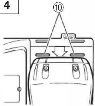
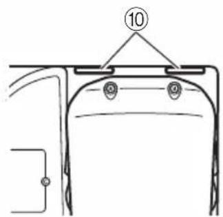
○Do not place electrically conductive cuttings, nails, steel wire, copper wire or other wire in the storage case.
○Either install the battery in the power tool or store by securely pressing into the battery cover until the ventilation holes are concealed to prevent short-circuits (See Fig. 1).
PRECAUTIONS REGARDING THE DUST-RESISTANCE AND WATER-PROOFING FUNCTIONS
This product conforms to IP56 protection class ratings (dust-resistance and water-proofing) for electrical equipment as stipulated by the international IEC regulations. (Only the main unit conforms to the IP56 protection class ratings when equipped with a battery.)
[Descriptions of IP Codes]
IP56
→ Protection rating for water penetration
Must be no adverse effects on the equipment when sprayed with powerful jets of water from all directions (water-proofed).
(100L of water per minute sprayed for approximately three minutes from a distance of approximately three meters with the use of a spray nozzle with a diameter of 12.5mm.)
Protection rating for external assault by solid objects
Dust that may cause adverse effects on the equipment must not be able to enter (dust-resistance).
(The equipment to be left non-operable in a test chamber in which particles of talcum powder with a diameter of less than 75 m are floating in the air with the use of an agitation pump at a rate of 2kg per cubic meter for eight hours.)
The equipment has been designed to withstand the effects of dust and water, but there is no guarantee that it will not malfunction. Do not use or leave the equipment in locations where it is subject to excessive amounts of dust, or in locations where it is submerged in water or subject to rainwater.
SPECIFICATIONS
POWER TOOL
| Model WH14DBAL2 WH18DBAL2 | |||||
| Voltage 14.4 V 18 V | |||||
| No-load Me speed | High mode 0 – 2800 | min | -1 | 0 – 2900 min-1 | |
| dium mode 0 – 2200 | min | -1 | 0 – 2200 min-1 | ||
| Low 2 mode 0 – 1500 | 0 min | -1 | 0 – 1500 min-1 | ||
| Low 1 mode 0 – 900 | min | -1 | 0 – 900 min-1 | ||
| Capacity | Ordinary bolt M5 – M14 | ||||
| High tension bolt M5 – M12 | |||||
| Tightening torque (Maximum) 160 N·m 160 N·m | |||||
| Rechargeable battery | BSL1430: Li-ion B$L1440: Li-ion BSL1814.4 V (3.0 Ah 8 cells) | 14.4 V (4.0 Ah 8 cells) | 30: Li-ion BSL1840: Li-ion18 V (3.0 Ah 10 cells) | 18 V (4.0 Ah 10 cells) | |
| Weight | 1.4 kg | 1.5 kg | |||
| Model WR14DBAL2 | WR18DBAL2 | ||||
| Voltage 14.4 V 18 V | |||||
| No-load Me speed | High mode 0 – 2800 min | -1 | 0 – 2900 min-1 | ||
| dium mode 0 – 2200 min | -1 | 0 – 2200 min-1 | |||
| Low 2 mode 0 – 1500 min | -1 | 0 – 1500 min-1 | |||
| Low 1 mode 0 – 900 min | -1 | 0 – 900 min-1 | |||
| Capacity | Ordinary bolt M6 – M16 | ||||
| High tension bolt M6 – M12 | |||||
| Tightening torque (Maximum) 165 N·m 165 N·m | |||||
| Rechargeable battery | BSL1430: Li-ion B$L1440: Li-ion BSL1814.4 V (3.0 Ah 8 cells) | 14.4 V (4.0 Ah 8 cells) | 30: Li-ion BSL1840: Li-ion18 V (3.0 Ah 10 cells) | 18 V (4.0 Ah 10 cells) | |
| Weight | 1.4 kg | 1.5 kg | |||
CHARGER
| Model UC18YRSL | |
| Charging voltage 14.4 V - 18 V | |
| Weight 0.6 kg | |
STANDARD ACCESSORIES
In addition to the main unit (1), the package contains the accessories listed in the table below.
| WH14DBAL2WH18DBAL2WR14DBAL2WR18DBAL2 | 1Charger 1 |
| 2Battery 2 | |
| 3 Plastic case 1 | |
| 4 Battery cover 1 |
Standard accessories are subject to change without notice.
OPTIONAL ACCESSORIES (Sold separately)
○Battery
(BSL1430, BSL1440) (BSL1830, BSL1840)
Optional accessories are subject to change without notice.
APPLICATION
○Driving and removing of machine screws, wood screws, tapping screws, etc.
○Tightening and loosening of all types of bolts and nuts, used for securing structural items
BATTERY REMOVAL/INSTALLATION
1. Battery removal
Hold the handle tightly and push the battery latch to remove the battery (see Fig. 2).
CAUTION:
Never short-circuit the battery.
2. Battery installation
Insert the battery while observing its polarities (see Fig. 2).
CHARGING
Before using the power tool, charge the battery as follows.
- Connect the charger's power cord to a receptacle. When the power cord is connected, the charger's pilot lamp will blink in red. (At 1-second intervals)
2. Insert the battery into the charger.
Firmly insert the battery into the charger until the line is visible, as shown in Fig. 3, 4.
3. Charging
When inserting a battery in the charger, charging will commence and the pilot lamp will light continuously in red.
When the battery becomes fully recharged, the pilot lamp will blink in red. (At 1-second intervals) (See Table 1)
(1) Pilot lamp indication
The indications of the pilot lamp will be as shown in Table 1, according to the condition of the charger or the rechargeable battery.
Table 1
| Indications of the pilot lamp | ||||
| The pilot lamp lights or blinks in red. | Before charging | Blinks |  | 0.5 |
| While charging | Lights | Lights continuously | ||
 seconds. (off for 0.5 seconds) seconds. (off for 0.5 seconds) | 0.5 | |||
| Charging complete | Blinks | |||
 seconds. (off for 0.1 seconds) seconds. (off for 0.1 seconds) | 0.1 | |||
| Charging impossible | Flickers | |||
 | ||||
| The pilot lamp lights in green. | Overheat standby | Lights | Lights continuously | |
(2) Regarding the temperatures of the rechargeable battery
The temperatures for rechargeable batteries are as shown in Table 2, and batteries that have become hot should be cooled for a while before being recharged.
Table 2 Recharging ranges of batteries
| Rechargeable batteries | Temperatures at which the battery can be recharged |
| BSL1430, BSL1830BSL1440, BSL1840 | 0^ - 50^ |
(3) Regarding recharging time
Depending on the combination of the charger and batteries, the charging time will become as shown in Table 3.
Table 3 Charging time (At 20°C)
| Battery\Charger | UC18YRSL |
| BSL1430, BSL1830 Approx | 45 min. |
| BSL1440, BSL1840 Approx | 60 min. |
NOTE:
The charging time may vary according to temperature and power source voltage.
-
Disconnect the charger's power cord from the receptacle.
-
Hold the charger firmly and pull out the battery. NOTE:
After operation, pull out batteries from the charger first, and then keep the batteries properly.
Regarding electric discharge in case of new batteries, etc.
As the internal chemical substance of new batteries and batteries that have not been used for an extended period is not activated, the electric discharge might be low when using them the first and second time. This is a temporary phenomenon, and normal time required for recharging will be restored by recharging the batteries 2-3 times.
How to make the batteries perform longer
(1) Recharge the batteries before they become completely exhausted.
When you feel that the power of the tool becomes weaker, stop using the tool and recharge its battery. If you continue to use the tool and exhaust the electric current, the battery may be damaged and its life will become shorter.
(2) Avoid recharging at high temperatures.
A rechargeable battery will be hot immediately after use. If such a battery is recharged immediately after use, its internal chemical substance will deteriorate, and the battery life will be shortened. Leave the battery and recharge it after it has cooled for a while.
CAUTION:
When the battery charger has been continuously used, the battery charger will be heated, thus constituting the cause of the failures. Once the charging has been completed, give 15 minutes rest until the next charging.
○If the battery is recharged when it is warm due to battery use or exposure to sunlight, the pilot lamp map light in green.
The battery will not be recharged. In such a case, let the battery cool before charging.
When the pilot lamp flickers in red (at 0.2-second intervals), check for and take out any foreign objects in the charger's battery installation hole. If there are no foreign objects, it is probable that the battery or charger is malfunctioning. Take it to your authorized Service Center.
PRIOR TO OPERATION
1. Preparing and checking the work environment
Make sure that the work site meets all the conditions laid forth in the precautions.
2. Checking the battery
Make sure that the battery is installed firmly. If it is at all loose it could come off and cause an accident.
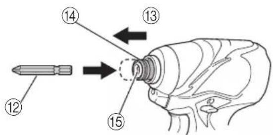
3. Installing the bit (WH14DBAL2 / WH18DBAL2)
Always follow the following procedure to install driver bit. (Fig. 5)
(1) Pull the guide sleeve away from front of the tool.
(2) Insert the bit into the hexagonal hole in the anvil.
(3) Release the guide sleeve and it returns to its original position.
CAUTION:
If the guide sleeve does not return to its original position, then the bit is not installed properly.
4. Selecting the socket matched to the bolt (WR14DBAL2 / WR18DBAL2)
Be sure to use a socket which is matched to the bolt to be tightened. Using an improper socket will not only result in insufficient tightening but also in damage to the socket or nut.
A worn or deformed hex. or square-holed socket will not give an adequate tightness for fitting to the nut or anvil, consequently resulting in loss of tightening torque.
Pay attention to wear of socket hole, and replace before further wear has developed.
5. Installing a socket (WR14DBAL2 / WR18DBAL2)
Select the socket to be used.
●Pin, O-ring type
(1) Align the hole in the socket with the hole in the anvil and insert the anvil into the socket.
(2) Insert the pin into the socket.
(3) Attach the ring to the groove on the socket.
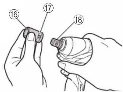
●Plunger type (Fig.6)
Align the plunger located in the square part of the anvil with the hole in the hex. socket. Then push the plunger, and mount the hex. socket on the anvil. Check that the plunger is fully engaged in the hole. When removing the socket, reverse the sequence.
●Retaining ring type
(1) Align the square portions of the socket and the anvil with each other.
(2) Make sure to firmly install the socket by pushing it all the way into the anvil.
(3) When removing the socket, pull it out of the anvil. CAUTION:
Please use the designated attachments which are listed in the operations manual and HiKOKI's catalog. Accidents or injuries could result from not doing so.
○Make sure to firmly install the socket in the anvil. If the socket is not firmly installed it might come out and cause injuries.
HOW TO USE
1. Check the rotational direction
The bit rotates clockwise (viewed from the rear side) by pushing the R-side of the push button.
The L-side of the push button is pushed to turn the bit counterclockwise. (See Fig. 7) (The (L) and (R) marks are provided on the body.)
2. Switch operation
○When the trigger switch is depressed, the tool rotates. When the trigger is released, the tool stops.
☐The rotational speed of the drill can be controlled by varying the amount that the trigger switch is pulled. Speed is low when the trigger switch is pulled slightly and increases as the trigger switch is pulled more.
NOTE:
A buzzing noise is produced when the motor is about to rotate. This is only a noise, not a machine failure.
3. Using the hook
The hook is used to hang up the power tool to your waist belt while working.
CAUTION:
○When using the hook, hang up the power tool firmly not to drop accidentally. If the power tool is dropped, it may lead to an accident.
When carrying the power tool with hooked to your waist belt, do not fit any bit to the tip of power tool. If the sharp bit such as drill is fitted to the power tool when carrying it with hooked to your waist belt, you will be injured.
○Install securely the hook. Unless the hook is securely installed, it may cause an injury while using.
(1) Removing the hook.
Remove the screws fixing the hook with Philips screw driver. (Fig. 8)
(2) Replacing the hook and tightening the screws. Install securely the hook in the groove of power tool and tighten the screws to fix the hook firmly. (Fig. 9)
4. About Remaining Battery Indicator
When pressing the remaining battery indicator switch, the remaining battery indicator lamp lights and the battery remaining power can be checked. (Fig.10) When releasing your finger from the remaining battery indicator switch, the remaining battery indicator lamp goes off. The table 4 shows the state of remaining battery indicator lamp and the battery remaining power.
Table 4
| State of lamp | Battery Remaining Power |
| The battery remaining power is enough. | |
| The battery remaining power is a half. | |
| The battery remaining power is nearly empty.Re-charge the battery soonest possible. |
As the remaining battery indicator shows somewhat differently depending on ambient temperature and battery characteristics, read it as a reference.
NOTE:
- Do not give a strong shock to the switch panel or break it. It may lead to a trouble. - To save the battery power consumption, the remaining battery indicator lamp lights while pressing the remaining battery indicator switch.
5. How to use the LED light
Every time you press the light switch on the switch panel, the LED light lights or goes off. (Fig. 11) To prevent the battery power consumption, turn off the LED light frequently.
CAUTION:
Do not expose directly your eye to the light by looking into the light. If your eye is continuously exposed to the light, your eye will be hurt.
NOTE:
To prevent the battery power consumption caused by forgetting to turn off the LED light, the light goes off automatically in about 15 minutes.
6. Tightening mode selector function (Fig. 12)
CAUTION:
- Do not subject the switch panel to shock or damage. - Select high/low mode while the trigger switch is released. Failure to do so could result in malfunction. (1) High/Low selector switch The rotation speed changes in 4 steps (900, 1500, 2200, 2800/2900 min ^-1 ) each time the high/low selector switch is pressed.
flowchart
graph LR
    A["Mobile Device"] --> B["Mobile Device"]
    B --> C["Mobile Device"]
    C --> D["Mobile Device"]
NOTE:
- The appropriate mode differs depending on the screw and the material being screwed. Drive in a few test screws and adjust the mode setting accordingly. - The high/low selector switch can only be set after the battery has been installed in the driver and the trigger switch has been pulled once.
Examples of tightening mode selector function settings
| Low 1 Low 2 | Medium High | |||||||
| Rotation speed |  | 900 min ^-1 |  | 1500 min ^-1 |  | 2200 min ^-1 |  | 2800 min ^-1 /2900 min ^-1 |
| Use | “Delicate work”Tightening small diameter screws (M6 or similar), etc. | “Light load work”Affixing plasterboard (select according to the hardness of the base material) etc. | “Heavy load work”Tightening long screws, coach screws, bolts, etc. | |||||
7. Tightening and loosening screws (WH14DBAL2 / WH18DBAL2)
Install the bit that matches the screw, line up the bit in the grooves of the head of the screw, then tighten it. Push the impact driver just enough to keep the bit fitting the head of the screw.
CAUTION
Applying the impact driver for too long tightens the screw too much and can break it.
Tightening a screw with the impact driver at an angle to that screw can damage the head of the screw and the proper force will not be transmitted to the screw. Tighten with this impact driver lined up straight with the screw.
8. Tightening and loosening bolts
A hex. socket matching the bolt or nut must first be selected. Then mount the socket on the anvil, and grip the nut to be tightened with the hex. socket. Holding the wrench in line with the bolt, press the power switch to impact the nut for several seconds. If the nut is only loosely fitted to the bolt, the bolt may turn with the nut, therefore mistaking proper tightening. In this case, stop impact on the nut and hold the bolt head with a wrench before restarting impact, or manually tighten the bolt and nut to prevent them slipping.
OPERATIONAL CAUTIONS
1. Resting the unit after continuous work
After use for continuous bolt-tightening work, rest the unit for 15 minutes or so when replacing the battery. The temperature of the motor, switch, etc., will rise if the work is started again immediately after battery replacement, eventually resulting in burnout.
NOTE:
Do not touch the metal parts, as it gets very hot during continuous work.
2. Cautions on use of the speed control switch
This switch has a built-in, electronic circuit which steplessly varies the rotation speed. Consequently, when the switch trigger is pulled only slightly (low speed rotation) and the motor is stopped while continuously driving in screws, the components of the electronic circuit parts may overheat and be damaged.
3. Use a tightening time suitable for the screw
The appropriate torque for a screw differs according to the material and size of the screw, and the material being screwed etc., so please use a tightening time suitable for the screw. In particular, if a long tightening time is used in the case of screws smaller than M8, there is a danger of the screw breaking, so please confirm the tightening time and the tightening torque beforehand.
4. Work at a tightening torque suitable for the bolt under impact
The optimum tightening torque for nuts or bolts differs with material and size of the nuts or bolts. An excessively large tightening torque for a small bolt may stretch or break the bolt. The tightening torque increases in proportion to the operaton time. Use the correct operating time for the bolt.
5. Holding the tool
Hold the impact wrench firmly with both hands. In this case hold the wrench in line with the bolt. It is not necessary to push the wrench very hard. Hold the wrench with a force just sufficient to counteract the impact force.
6. Confirm the tightening torque
The following factors contribute to a reduction of the tightening torque. So confirm the actual tightening torque needed by screwing up some bolts before the job with a hand torque wrench. Factors affecting the tightening torque are as follows.
(1) Voltage
When the discharge margin is reached, voltage decreases and tightening torque is lowered.
(2) Operating time
The tightening torque increases when the operating time increases. But the tightening torque does not increase above a certain value even if the tool is driven for a long time.
(3) Diameter of bolt
The tightening torque differs with the diameter of the bolt. Generally a larger diameter bolt requires larger tightening torque.
(4) Tightening conditions
The tightening torque differs according to the torque ratio; class, and length of bolts even when bolts with the same size threads are used. The tightening torque also differs according to the condition of the surface of workpiece through which the bolts are to be tightened. When the bolt and nut turn together, torque is greatly reduced.
(5) Using optional parts (WR14DBAL2 / WR18DBAL2)
The tightening torque is reduced a little when an extension bar, universal joint or a long socket is used.
(6) Clearance of the socket (WR14DBAL2 / WR18DBAL2) A worn or deformed hex. or a square-holed socket will not give an adequate tightness to the fitting between the nut or anvil, consequently resulting in loss of tightening torque.
Using an improper socket which does not match to the bolt will result in an insufficient tightening torque.
(7) Tightening torque varies, depending on the battery's charge level.
MAINTENANCE AND INSPECTION
1. Inspecting the driver bit (WH14DBAL2 / WH18DBAL2)
Using a broken bit or one with a worn out tip is dangerous because the bit can slip. Replace it.
2. Inspecting the socket (WR14DBAL2 / WR18DBAL2)
A worn or deformed hex. or a square-holed socket will not give an adequate tightness to the fitting between the nut or anvil, consequently resulting in loss of tightening torque. Pay attention to wear of a socket holes periodically, and replace with a new one if needed.
3. Inspecting the mounting screws
Regularly inspect all mounting screws and ensure that they are properly tightened. Should any of the screws be loose, retighten them immediately. Failure to do so may result in serious hazard.
4. Maintenance of the motor
The motor unit winding is the very "heart" of the power tool.
Exercise due care to ensure the winding does not become damaged and/or wet with oil or water.
5. Cleaning of the outside
When the impact driver is stained, wipe with a soft dry cloth or a cloth moistened with soapy water. Do not use chloric solvents, gasoline or paint thinner, as they melt plastics.
6. Storage
Store the impact driver in a place in which the temperature is less than 40^ C, and out of reach of children.
NOTE:
Make sure that the battery is fully charged when stored for a long period (3 months or more). The battery with smaller capacity may not be able to be charged when used, if stored for a long period.
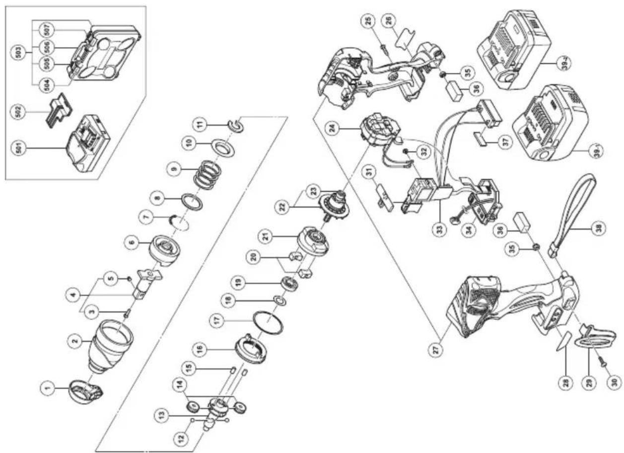
7. Service parts list
A: Item No.
B: Code No.
C: No. Used
D: Remarks
CAUTION
Repair, modification and inspection of HiKOKI Power Tools must be carried out by a HiKOKI Authorized Service Center.
This Parts List will be helpful if presented with the tool to the HiKOKI Authorized Service Center when requesting repair or other maintenance.
In the operation and maintenance of power tools, the safety regulations and standards prescribed in each country must be observed.
MODIFICATIONS
HiKOKI Power Tools are constantly being improved and modified to incorporate the latest technological advancements.
Accordingly, some parts (i.e. code numbers and/or design) may be changed without prior notice.
Important notice on the batteries for the HiKOKI cordless power tools
Please always use one of our designated genuine batteries. We cannot guarantee the safety and performance of our cordless power tool when used with batteries other than these designated by us, or when the battery is disassembled and modified (such as disassembly and replacement of cells or other internal parts).
GUARANTEE
We guarantee HiKOKI Power Tools in accordance with statutory/country specific regulation. This guarantee does not cover defects or damage due to misuse, abuse, or normal wear and tear. In case of complaint, please send the Power Tool, undismantled, with the GUARANTEE CERTIFICATE found at the end of this Handling instruction, to a HiKOKI Authorized Service Center.
NOTE:
Due to HiKOKI's continuing program of research and development, the specifications herein are subject to change without prior notice..
Information concerning airborne noise and vibration
The measured values were determined according to EN60745 and declared in accordance with ISO 4871.
Measured A-weighted sound power level:
WH14DBAL2: 92 dB (A)
WH18DBAL2: 91 dB (A)
WR14DBAL2: 91 dB (A)
WR18DBAL2: 91 dB (A)
Measured A-weighted sound pressure level:
WH14DBAL2: 73 dB (A)
WH18DBAL2: 72 dB (A)
WR14DBAL2: 72 dB (A)
WR18DBAL2: 72 dB (A)
Uncertainty KpA: 3 dB (A).
Wear hearing protection.
Vibration total values (triax vector sum) determined according to EN60745.
Impact tightening of fasteners of the maximum capacity of the tool:
Vibration emission value a_h=WH14DBAL2:9.2 m/s^2
WH18DBAL2: 10.6 m/s²
WR14DBAL2: 8.9 m/s ^4
WR18DBAL2: 8.6 m/s ^4
Uncertainty K = 1.5 m/s ^4
The declared vibration total value has been measured in accordance with a standard test method and may be used for comparing one tool with another.
It may also be used in a preliminary assessment of exposure.
WARNING
○The vibration emission during actual use of the power tool can differ from the declared total value depending on the ways in which the tool is used.
○Identify safety measures to protect the operator that are based on an estimation of exposure in the actual conditions of use (taking account of all parts of the operating cycle such as the times when the tool is switched off and when it is running idle in addition to the trigger time).
WR14DBAL2: 91 dB (A)
WR18DBAL2: 91 dB (A)
WR14DBAL2: 72 dB (A)
WR18DBAL2: 72 dB (A)
WR14DBAL2: 91 dB (A)
WR18DBAL2: 91 dB (A)
WR14DBAL2: 72 dB (A)
WR18DBAL2: 72 dB (A)
Incertitude KpA: 3 dB (A)
WR14DBAL2: 91 dB (A)
WR18DBAL2: 91 dB (A)
WR14DBAL2: 72 dB (A)
WR18DBAL2: 72 dB (A)
flowchart
graph LR
    A["Mobile Device"] --> B["Mobile Phone Icon"]
    B --> C["Mobile Phone Icon with Hand gestures"]
    C --> D["Mobile Phone Icon with Hand gestures"]
OPMERKING:
WR14DBAL2: 91 dB (A)
WR18DBAL2: 91 dB (A)
WR14DBAL2: 72 dB (A)
WR18DBAL2: 72 dB (A)
WR14DBAL2: 91 dB (A)
WR18DBAL2: 91 dB (A)
WR14DBAL2: 72 dB (A)
WR18DBAL2: 72 dB (A)
Duda KpA: 3 dB (A)
WR14DBAL2: 91 dB (A)
WR18DBAL2: 91 dB (A)
WR14DBAL2: 72 dB (A)
WR18DBAL2: 72 dB (A)
| A B C D | A B C D | ||||
| 1 334515 1 | 34 334836 1 | "WR14DBAL2" | |||
| 2 334514 1 | 34 334359 1 | "WR18DBAL2" | |||
| 3 323542 1 | 35 327002 2 | ||||
| 4 329718 1 | "3, 5" | 36 328644 2 | |||
| 5 323541 1 | 37 331101 1 | ||||
| 6 326789 1 | 38 306952 1 | ||||
| 7 959148 28 | D3.175 | 39-1 - - - - - 2 | "WR14DBAL2" | ||
| 8 315978 1 | 39-2 - - - - - 2 | "WR18DBAL2" | |||
| 9 321660 1 | 501 - - - - - 1 | UC18YRSL | |||
| 10 316172 1 | 502 329897 1 | ||||
| 11 316171 1 | 503 329440 1 | "504-507" | |||
| 12 959154 2 | D5.556 | 504 334233 2 | |||
| 13 330658 1 | 505 334235 1 | ||||
| 14 326295 2 | 506 334232 1 | ||||
| 15 319914 2 | 507 334234 1 | ||||
| 16 330657 1 | |||||
| 17 983852 1 | S-42 | ||||
| 18 330855 1 | |||||
| 19 323118 1 | 6901VV-N | ||||
| 20 333952 2 | |||||
| 21 326786 1 | |||||
| 22 334565 1 | "23" | ||||
| 23 333784 2 | 624DD | ||||
| 24 340841 1 | "WR14DBAL2" | ||||
| 24 340832 1 | "WR18DBAL2" | ||||
| 25 301653 9 | D4×20 | ||||
| 26 - - - - - 1 | |||||
| 27 334151 1 | "WR14DBAL2" | ||||
| 27 334365 1 | "WR18DBAL2" | ||||
| 28 330662 1 | |||||
| 29 330666 1 | |||||
| 30 327001 1 | |||||
| 31 321661 1 | |||||
| 32 994532 2 | M3×5 | ||||
| 33 334215 1 | "WR14DBAL2" | ||||
| 33 334906 1 | "WR18DBAL2" | ||||
natural_image
Line drawing of a quill pen with inkwell (no text or symbols)| English | Nederlands | ||
| GUARANTEE CERTIFICATE1Model No.2Serial No.3Date of Purchase4Customer Name and Address5Dealer Name and Address(Please stamp dealer name and address) | GARANTIEBEWIJS1Modelnummer2Serienummer3Datum van aankoop4Naam en adres van de gebruiker5Naam en adres van de handelaar(Stempel a.u.b. naam en adres vande de handelaar) | ||
| Deutsch | Español | ||
| GARANTIESCHEIN1Modell-Nr.2Serien-Nr.3Kaufdaturn4Name und Anschrift des Kunden5Name und Anschrift des Händlers(Bitte mit Namen und Anschrift des Handlers abstempeln) | CERTIFICADO DE GARANTIA1Número de modelo2Número de serie3Fecha de adquisición4Nombre y dirección del cliente5Nombre y dirección del distribudor(Se ruega poner el sellú del distribudor con su nombre y dirección) | ||
| Français Português | |||
| CERTIFICAT DE GARANTIE1No. de modèle2No. de série3Date d'achat4Nom et adresse du client5Nom et adresse du revendeur(Cachet portant le nom et l'adresse du revendeur) | CERTIFICADO DE GARANTIA1Número do modelo2Número do série3Data de compra4Nome e morada do cliente5Nome e morada do distribuidor(Por favor, carímbe o nome e morada do distribuidor) | ||
| Italiano | |||
| CERTIFICATO DI GARANZIA1Modello2N° di serie3Data di acquisto4Nome e indirizzo dell'acquirente5Nome e indirizzo del rivenditore(Si prega di apporre il timbro con questi dati) | |||
HiKOKI
| 1 | |
| 2 | |
| 3 | |
| 4 | |
| 5 |
Siemensring 34, 47877 willich, Germany
Tel: +49 2154 49930
Fax: +49 2154 499350
URL: http://www.hikoki-powertools.de
Hikoki Power Tools Netherlands B.V.
Brabanthaven 11, 3433 PJ Nieuwegein, The Netherlands
Tel: +31 30 6084040
Fax: +31 30 6067266
URL: http://www.hikoki-powertools.nl
Hikoki Power Tools (U.K.) Ltd.
Precedent Drive, Rooksley, Milton Keynes, MK 13, 8PJ,
United Kingdom
Tel: +44 1908 660663
Fax: +44 1908 606642
URL: http://www.hikoki-powertools.uk
Hikoki Power Tools France S.A.S.
Hikoki Power Tools Belgium N.V./S.A.
Koningin Astridlaan 51, B-1780 Wemmel, Belgium
Tel: +32 2 460 1720
Fax: +32 2 460 2542
URL http://www.hikoki-powertools.be
Hikoki Power Tools Italia S.p.A
Via Piave 35, 36077, Altavilla Vicentina (VI), Italy
Tel: +39 0444 548111
Fax: +39 0444 548110
URL: http://www.hikoki-powertools.it
Hikoki Power Tools Ibérica, S.A.
C/ Puigbarral, 26-28, Pol. Ind. Can Petit, 08227 Terrassa
(Barcelona), Spain
Tel: +34 93 735 6722
Fax: +34 93 735 7442
URL: http://www.hikoki-powertools.es
natural_image
Line drawing of a quill pen with inkwell (no text or symbols)
natural_image
Line drawing of a quill pen with inkwell (no text or symbols)| English Nederlands | ||
| EC DECLARATION OF CONFORMITYWe declare under our sole responsibility that Cordless Impact Driver/Wrench, identified by type and specific identification code *1), is in conformity with all relevant requirements of the directives *2) and standards *3). Technical fi le at *4) – See below.The European Standard Manager at the representative office in Europe is authorized to compile the technical fi le.The declaration is applicable to the product affi xed CE marking. | EC VERKLARING VAN CONFORMITEITWij verklaren onder onze eigen verantwoordelijkheid dat Snoerloze slagschroevendraaier/sleutel, geïdentificeerd door het type en de specifieke identificatiecode*1), voldoet aan alle relevante bepalingen van de richtlijnen*2) en normen *3). Technische documentatie bij*4) – zie onder.De Europese Normen Manager bij de vertegenwoordiging in Europa is gemachtigd om het technisch dossier samen te stellen.Deze verklaring is van toepassing op producten voorzien van de CE-markeringen. | |
| Deutsch Español | ||
| EG-KONFORMITÄTSERKLÄRUNGWir erklären in alleiniger Verantwortung, dass der durch den Typ und den spezifischen Identifizierungscode *1) identifizierte Akku-Schlagschrauber allen einschlägigen Bestimmungen der Richtlinien *2) und Normen *3) entspricht. Technische Unterlagen unter *4) – Siehe unten.Die Leitung der repräsentativen Behörde für europäische Normen und Richtlinien ist berechtigt, die technischen Unterlagen zusammenzustellen.Die Erklärung gilt für die an dem Produkt angebrachte CE-Kennzeichnung. | DECLARACIÓN DE CONFORMIDAD DE LA CDEclaramos bajo nuestra única responsabilidad que el Atomillador/Llave de impacto a batería, identificados por tipo y por código de identificación específico *1), están en conformidad con todas las disposiciones correspondientes de las directivas *2) y de las normas *3). Documentación técnica en *4) – Ver a continuación.El Director de Normas Europeas en la oficina de representación en Europa está autorizado para elaborar el expediente técnico.La declaración se aplica al producto con marcas de la CE. | |
| Français PortuguêsDECLARATION DE CONFORMITE CENous déclarons sous notre entière responsabilité que la perceuse/visseuse à percussion sur batterie, identifiée par le type et le code d'identification spécifique *1) est en conformité avec toutes les exigences applicables des directives *2) et des normes *3). Dossier technique en *4) - Voir ci-dessous.Le Gestionnaire des normes européennes du bureau de représentation en Europe est autorisé à constituer le dossier technique.Cette déclaration s'applique aux produits désignés CE. | DECLARAÇÃO DE CONFORMIDADE CEDeclaramos, sob nossa única e inteira responsabilidade, que Aparafusadora/Chave de Impacto a Bateria, identificada por tipo e código de identificação específico *1), está em conformidade com todos os requerimentos relevantes das diretivas *2) e normas *3). Ficheiro técnico em *4)-Consulte abaixo.O Gestor de Normas Europeas no escritório de representação na Europa está autorizado a compilar o fi cheiro técnico.A declaração aplica-se aos produtos com marca CE. | |
| Italiano | ||
| DICHIARAZIONE DI CONFORMITÀ CEDichiariamo sotto la nostra esclusiva responsabilità che l'Avvitatore a impulso a batteria per viti e bulloni, identificato dal tipo e dal codice identificativo specifico *1), è conforme a tutti i requisiti delle direttive *2) e degli standard *3). Documentazione tecnica presso *4) – Vedere sotto.Il gestore delle norme europee presso l'ufficio di rappresentanza in Europa è autorizzato a compilare il fascicolo tecnico.La dichiarazione è applicabile ai prodotti cui sono applicati i marchi CE. | ||
| *1) WR14DBAL2 C345084RWR18DBAL2 C345090R C349164SWH14DBAL2 C345072RWH18DBAL2 C345078R*2) 2006/42/EC, 2014/30/EU, 2014/35/EU, 2011/65/EU*3) EN60745-1:2009+A11:2010EN60745-2-2:2010EN60335-1:2012+A11:2014EN60335-2-29:2004+A2:2010EN55014-1:2006+A1:2009+A2:2011EN55014-2:1997+A1:2001+A2:2008 | ||
| *4) Representative office in EuropeHikoki Power Tools Deutschland GmbHSiemensring 34, 47877 Willich, GermanyHead office in JapanKoki Holdings Co., Ltd.Shinagawa Intercity Tower A, 15-1, Konan 2-chome,Minato-ku, Tokyo, Japan | 29. 6. 2018Naoto YamashiroEuropean Standard Manager29. 6. 2018A. NakagawaCorporate Officer | |


- GENERAL POWER TOOL SAFETY WARNINGS
- WARNING
- 6) Service
- PRECAUTION
- PRECAUTIONS FOR CORDLESS IMPACT DRIVER (WH14DBAL2 / WH18DBAL2)
- PRECAUTIONS FOR CORDLESS IMPACT WRENCH (WR14DBAL2 / WR18DBAL2)
- CAUTION ON LITHIUM-ION BATTERY
- CAUTION
- PRECAUTIONS REGARDING THE DUST-RESISTANCE AND WATER-PROOFING FUNCTIONS
- [Descriptions of IP Codes]
- IP56
- → Protection rating for water penetration
- Protection rating for external assault by solid objects
- SPECIFICATIONS
- STANDARD ACCESSORIES
- OPTIONAL ACCESSORIES (Sold separately)
- APPLICATION
- BATTERY REMOVAL/INSTALLATION
- Battery removal
- CAUTION:
- Battery installation
- CHARGING
- Insert the battery into the charger.
- Charging
- NOTE:
- How to make the batteries perform longer
- PRIOR TO OPERATION
- Preparing and checking the work environment
- Checking the battery
- Installing the bit (WH14DBAL2 / WH18DBAL2)
- Selecting the socket matched to the bolt (WR14DBAL2 / WR18DBAL2)
- Installing a socket (WR14DBAL2 / WR18DBAL2)
- HOW TO USE
- Check the rotational direction
- Switch operation
- Using the hook
- About Remaining Battery Indicator
- How to use the LED light
- Tightening mode selector function (Fig. 12)
- Tightening and loosening screws (WH14DBAL2 / WH18DBAL2)
- Tightening and loosening bolts
- OPERATIONAL CAUTIONS
- Resting the unit after continuous work
- Cautions on use of the speed control switch
- Use a tightening time suitable for the screw
- Work at a tightening torque suitable for the bolt under impact
- Holding the tool
- Confirm the tightening torque
- MAINTENANCE AND INSPECTION
- Inspecting the driver bit (WH14DBAL2 / WH18DBAL2)
- Inspecting the socket (WR14DBAL2 / WR18DBAL2)
- Inspecting the mounting screws
- Maintenance of the motor
- Cleaning of the outside
- Storage
- Service parts list
- MODIFICATIONS
- Important notice on the batteries for the HiKOKI cordless power tools
- GUARANTEE
- Information concerning airborne noise and vibration
- OPMERKING:
- HiKOKI
- Hikoki Power Tools Netherlands B.V.
- Hikoki Power Tools (U.K.) Ltd.
- Hikoki Power Tools France S.A.S.
- Hikoki Power Tools Belgium N.V./S.A.
- Hikoki Power Tools Italia S.p.A
- Hikoki Power Tools Ibérica, S.A.
Brand : HiKOKI
Model : WH14DBAL2
Category : Screwdriver