
M6SB - String Trimmer HiKOKI - Free user manual and instructions
Find the device manual for free M6SB HiKOKI in PDF.

| Product type | Trimmer (router) |
| Brand | HiKOKI |
| Model | M6SB |
| Supply voltage | 110 V / 230 V / 240 V (depending on region) |
| Rated power | 440 W |
| No-load speed | 30,000 rpm |
| Collet capacity | 6 mm or 6.35 mm (1/4") |
| Weight (main unit) | 1.4 kg |
| Applications | Cutting plywood, bevel cuts, grooves, chiseling, cutting-off |
| Included accessories | Machine guide piece, straight guide piece, template guide (with M4 screws), 17/19 mm wrench |
| Sound power level | 95 dB(A) |
| Sound pressure level | 84 dB(A) |
| Vibration value | 1.0 m/s² |
| Safety | Wear protective equipment (safety glasses, dust mask, ear plugs); avoid explosive atmospheres; use a residual current device in damp conditions |
| Maintenance | Regular check of carbon brushes, cutter, and mounting screws |
| Storage | Out of reach of children and infirm persons |
| Repairability | Entrust repairs to an authorized HiKOKI service center |
Frequently Asked Questions - M6SB HiKOKI
User questions about M6SB HiKOKI
0 question about this device. Answer the ones you know or ask your own.
Ask a new question about this device
Download the instructions for your String Trimmer in PDF format for free! Find your manual M6SB - HiKOKI and take your electronic device back in hand. On this page are published all the documents necessary for the use of your device. M6SB by HiKOKI.
USER MANUAL M6SB HiKOKI
natural_image
Line drawing of a manual electric drill press device with no visible text or symbolsRead through carefully and understand these instructions before use.
2
3
4
5
natural_image
Technical line drawing of a mechanical device with a wooden base and pipe connection (no text or symbols)6
7
8
9
natural_image
Line drawing of a hand operating a handheld device with wires and a small component (no text or symbols)10
11
natural_image
Line drawing of a hand using a tool to press or install a wooden block (no text or symbols present)12
13
natural_image
Line drawing of a hand operating a machine tool on a workbench (no text or symbols)14
15
16
| English Deutsch Français Italiano | ||||
| 1 | Top view | Arsicht von oben | Vue de haut | Vista da sopra |
| 2 | Hollow | Hohl | Creux | Vuoto |
| 3 | Collet chuck | Spannfutter | Mandrin à pince | Mandrino a pinza |
| 4 | Loosen | Lockern | Desserrer | Allentare |
| 5 | Tighten | Anziehen | Serrer | Serrare |
| 6 | Spindle lock | Spindelverriegelung | Verrou d'axc | Blocco dell'alberino |
| 7 | Knob bolt (A) | Rändelschraube (A) | Bouton de boulonnage (A) | Bullone a manopola (A) |
| 8 | Bit | Fräse | Couteau | Punta |
| 9 | Scale | Skala | Echelle | Scala |
| 10 | Wing nut | Flügelmutter | Ecrou à oreilles | Dado ad alette |
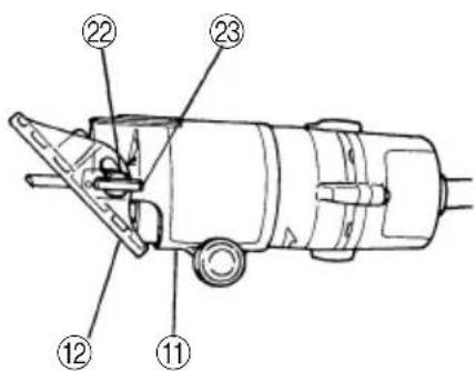
| 11 | Base ass'y | Zurichttischmontage | Ensemble de base | Gruppo basamento |
| 12 | Base | Zurichttisch | Base | Basamento |
| 13 | Tighten | Anziehen | Serrer | Serrare |
| 14 | Loosen | Lockern | Desserrer | Allentare |
| 15 | Pinion | Ritzel | Pignon | Pignone |
| 16 | Rack portion | Zahnstangenteil | Section crémaillère | Parte della staffa |
| 17 | Keep the bit separated from the material | Mit der Fräse nicht das Metall berühren | Tenir le coutear séparé du matériau | Tenere la punta scostata dal materiale |
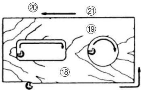
| 18 | Material | Material | Matériau | Materiale |
| 19 | For cutting inner circumference | Zurichten von Innenkanten | Pour coupe de la circonférence interne | Per tagliare una circonferenza interna |
| 20 | For cutting the external circumference | Fräsen der Außenkant | Pour coupe de la circonférence externe | Per tagliare la circonferenza esterna |
| 21 | Trimmer fedding direction | Vorschubrichtung der Kantenfräse | Direction de l'avance de la machine | Senso di avanzamento della rifinitrice |
| 22 | Index mark | Indexmarkierung | Repère d'index | Segno di indice |
| 23 | Wing bolt | Flügelschraube | Boulon papillon | Bullone ad alette |
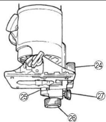
| 24 | Knob bolt (B) | Rändelschraube (B) | Bouton de boulonnage (B) | Bullone a manopola (B) |
| 25 | Guide pin | Führungsstift | Goupille de la pièce de guidage | Punta di guida |
| 26 | Knob bolt (C) | Rändelschraube (C) | Bouton de boulonnage (C) | Bullone a manopola (C) |
| 27 | Stopscrew (B) | Anschlagschraube (B) | Vis d'arrêt (B) | Vite d'arresto (B) |
| 28 | Knob bolt (D) | Rändelschraube (D) | Bouton de boulonnage (D) | Bullone a manopola (D) |
| 29 | Straight guide | Gerade Führung/Parallelanschlag | Pièce de guidage droite | Guida lineare |
| 30 | M4 Screw | M4-Schraube | Vis M4 | Vite M4 |
| 31 | Template guide | Schablonenführung | Guide-gabarit | Guida per sagoma |
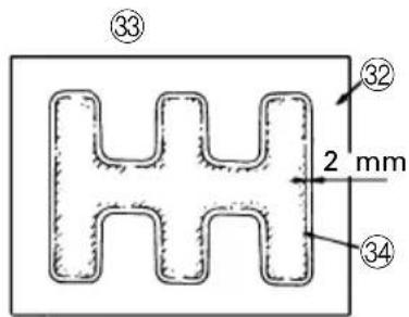
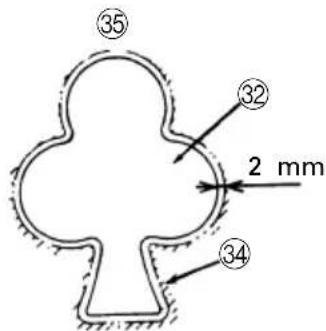
| 32 | Template | Schablone | Gabarit | Sagoma |
| 33 | Inner edge cutting | Innenkantenschneiden | Découpe suivant le bord intérieur | Taglio sul bordo interno |
| 34 | Cutting line | Schneidlinie | Ligne de découpe | Linea di taglio |
| 35 | Outer edge sutting | Außenkantenschneiden | Découpe suivant le extérieur | Taglio sul bordo esterno |
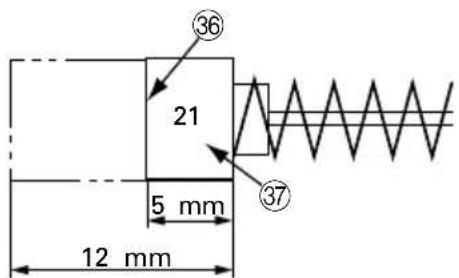
| 36 | Wear limit | Verschleißgrenze | Limite d'usure | Limite di usura |
| 37 | No. of carbon brush | Nr. der Kohlebürste | N° du balai carbone | N. della spazzola di carbone |
| Nederlands Español | Português | ||
| 1 | Bovenaanzicht | Vista superior | Vista de cima |
| 2 | Hol | Hueco | Oco |
| 3 | Freeshouder | Boquilla de mordazas | Pinça de aperto |
| 4 | Losdraaien | Soltar | Desapertar |
| 5 | Vastdraaien | Apretar | Apertar |
| 6 | Asvergrendeling | Seguro del eje | Bloqueio do eixo |
| 7 | Gekartelde schroef (A) | Perno de cabeza (A) | Parafuso de manípulo (A) |
| 8 | Frees | Broca | Ponta |
| 9 | Schaal | Escala | Escala |
| 10 | Vleugelmoer | Tuerca de mariposa | Porca de orelhas |
| 11 | Grondplaatmontage | Conjunto de la base | Conjunto da base |
| 12 | Grondplaat | Base | Base |
| 13 | Vastdraaien | Apretar | Apertar |
| 14 | Losdraaien | Soltar | Desapertar |
| 15 | Tandwiel | Piñón | Pinhão |
| 16 | Achterdeel | Parte de la cremallera | Porção de cremalheira |
| 17 | Met de frees het metaal niet aanraken | Mantener la broca separada del material | Mantenha a ponta separada do material |
| 18 | Materiaal | Material | Material |
| 19 | Het effenen van binnenkanten | Para cortar la circunferencia interna | Para cortar uma circunferência interna |
| 20 | Het frezen van de buitenkant | Para cortar la circunferencia externa | Para cortar uma circunferência externa |
| 21 | Richting waarin de machine naar voren geschoven wordt | Dirección de alimentación de la cortadora de cerco | Direcção de entrada do cortador |
| 22 | Indexmarkering | Marca de referencia | Marca de referência |
| 23 | Vleugelbout | Perno de aletas | Parafuso de orelhas |
| 24 | Gekartelde schroef (B) | Perno de cabeza (B) | Parafuso de manípulo (B) |
| 25 | Leistift | Pasador de guía | Pino guia |
| 26 | Gekartelde schroef (C) | Perno de cabeza (C) | Parafuso de manípulo (C) |
| 27 | Aanslagschroef (B) | Tornillo-stop (B) | Parafuso batente (B) |
| 28 | Gekartelde schroef (D) | Perno de cabeza (D) | Parafuso de manípulo (D) |
| 29 | Vlakgeleider/parallelgeleider | Guía derecha | Guia direito |
| 30 | M4 schroef | Tornillo M4 | Parafuso M4 |
| 31 | Schabloongeleider | Guía patrón | Modelo guia |
| 32 | Schabloon | Patrón | Modelo |
| 33 | Freezen van binnenrand | Corte por borde inferior | Cortar extremidade interior |
| 34 | Freeslijn | Línea de corte | Linha de corte |
| 35 | Freezen van buitenrand | Corte por el borde exterior | Cortar extremidade exterior |
| 36 | Slijtagegrens | Límite de uso | Limite de desgaste |
| 37 | Nr. van de koolborstel | N° de carbón de contacto | N.o da escova de carbono |
| Symbols⚠WARNINGThe following show symbols used for the machine. Be sure that you understand their meaning before use. | Symbole⚠WARNUNGDie folgenden Symbole werden für diese Maschine verwendet. Achten Sie darauf, diese vor der Verwendung zu verstehen. | Symboles⚠AVERTISSEMENTLes symboles suivants sont utilisés pour l’outil. Bien se familiariser avec leur signification avant d’utiliser l’outil. | Simboli⚠AVVERTENZADi seguito mostriamo i simboli usati per la macchina. Assicurarsi di comprenderne il significato prima dell’uso. | |
 | Read all safety warnings and all instructions.Failure to follow the warnings and instructions may result in electric shock, fire and/or serious injury. | Lesen Sie sämtliche Sicherheitshinweise und Anweisungen durch.Wenn die Warnungen und Anweisungen nicht befolgt werden, kann es zu Stromschlag, Brand und/oder ernsthaftenVerletzungen kommen. | Lire tous les avertissements de sécurité et toutes les instructions.Tout manquement à observer ces avertissements et instructions peut engendrer des chocs électriques, des incendies et/ou des blessures graves. | Leggere tutti gli avvertimenti di sicurezza e tutte le istruzioni.La mancata osservanza degli avvertimenti e delle istruzioni potrebbe essere causa di scosse elettriche, incendi e/o gravi lesioni. |
 | Only for EU countriesDo not dispose of electric tools together with household waste material!In observance of European Directive 2002/96/EC on waste electrical and electronic equipment and its implementation in accordance with national law, electric tools that have reached the end of their life must be collected separately and returned to an environmentally compatible recycling facility. | Nur für EU-Länder Werfen Sie Elektrowerkzeuge nicht in den Hausmüll!Gemäss Europäischer Richtlinie 2002/96/EG über Elektro- und Elektronik-Altgeräte und Umsetzung in nationales Recht müssen verbrauchte Elektrowerkzeuge getrennt gesammelt und einer umweltgerechten Wiederververtung zugeführt werden. | Pour les pays européens uniquementNe pas jeter les appareils électriques dans les ordures ménagères!Conformément à la directive européenne 2002/96/EG relative aux déchets d’équipements électriques ou électroniques (DEEE), et à sa transposition dans la législation nationale, les appareils électriques doivent être collectés à part et être soumis à un recyclage respectueux de l’environnement. | Solo per Paesi UENon gettare le apparecchiature elettriche tra i rifiuti domestici.Secondo la Direttiva Europea 2002/96/CE sui rifiuti di apparecchiature elettriche ed elettroniche e la sua attuazione in conformità alle norme nazionali, le apparecchiature elettriche esauste devono essere raccolte separatamente, al fine di essere reimpiegate in modo eco-compatibile. |
| Symbolen⚠WAARSCHUWINGHieronder staan symbolen afgebeeld die van toepassing zijn op deze machine. U moet de betekenis hiervan begrijpen voor gebruik. | Símbolos⚠ADVERTENCIAA continuación se muestran los símbolos usados para la máquina. Asegúrese de comprender su significado antes del uso. | Símbolos⚠AVISOA seguir aparecem os símbolos utilizados pela máquina. Assimile bem seus significados antes do uso. | ||
 | Lees alle waarschuwingen en instructies aandachtig door.Nalating om de waarschuwingen en instructies op te volgen kan in een elektrische schok, brand en/of ernstig letsel resulteren. | Lea todas las instrucciones y advertencias de seguridad.Si no se siguen las advertencias e instrucciones, podría producirse una descarga eléctrica, un incendio y/o daños graves. | Leia todas as instruções e avisos de segurança.Se não seguir todas as instruções e os avisos, pode provocar um choque eléctrico, incêndio e/ou ferimentos graves. | |
 | Alleen voor EU-landen Geef elektrisch gereedschap niet met het huisvuil mee!Volgens de Europese richtlijn 2002/96/EG inzake oude elektrische en elektronische apparaten en de toepassing daarvan binnen de nationale wetgeving, dient gebruikt elektrisch gereedschap gescheiden te worden ingezameld en te worden afgevoerd naar een recycle bedrijf dat voldoet aan de geldende milieu-eisen. | Sólo para países de la Unión Europea¡No deseche los aparatos eléctricos junto con los residuos domésticos!De conformidad con la Directiva Europea 2002/96/CE sobre residuos de aparatos eléctricos y electrónicos y su aplicación de acuerdo con la legislación nacional, las herramientas eléctricas cuya vida útil haya llegado a su fin se deberán recoger por separado y trasladar a una planta de reciclaje que cumpla con las exigencias ecológicas. | Apenas para países da UE Não deite ferramentas eléctricas no lixo doméstico!De acordo com a directiva europeia 2002/96/CE sobre ferramentas eléctricas e electrónicas usadas e a transposição para as leis nacionais, as ferramentas eléctricas usadas devem ser recolhidas em separado e encaminhadas a uma instalação de reciclagem dos materiais ecológica. |
GENERAL POWER TOOL SAFETY WARNINGS

WARNING
Read all safety warnings and all instructions.
Failure to follow the warnings and instructions may result in electric shock, fire and/or serious injury.
Save all warnings and instructions for future reference.
The term "power tool" in the warnings refers to your mains-operated (corded) power tool or battery-operated (cordless) power tool.
1) Work area safety
a) Keep work area clean and well lit.
Cluttered or dark areas invite accidents.
b) Do not operate power tools in explosive atmospheres, such as in the presence of flammable liquids, gases or dust.
Power tools create sparks which may ignite the dust or fumes.
c) Keep children and bystanders away while operating a power tool.
Distractions can cause you to lose control.
2) Electrical safety
a) Power tool plugs must match the outlet.
Never modify the plug in any way.
Do not use any adapter plugs with earthed (grounded) power tools.
Unmodified plugs and matching outlets will reduce risk of electric shock.
b) Avoid body contact with earthed or grounded surfaces, such as pipes, radiators, ranges and refrigerators. There is an increased risk of electric shock if you body is earthed or grounded.
c) Do not expose power tools to rain or wet conditions. Water entering a power tool will increase the risk of electric shock.
d) Do not abuse the cord. Never use the cord for carrying, pulling or unplugging the power tool. Keep cord away from heat, oil, sharp edges or moving parts. Damaged or entangled cords increase the risk of electric shock.
e) When operating a power tool outdoors, use an extension cord suitable for outdoor use. Use of a cord suitable for outdoor use reduces the risk of electric shock.
f) If operating a power tool in a damp location is unavoidable, use a residual current device (RCD) protected supply. Use of an RCD reduces the risk of electric shock.
3) Personal safety
a) Stay alert, watch what you are doing and use common sense when operating a power tool.
Do not use a power tool while you are tired or under the influence of drugs, alcohol or medication.
A moment of inattention while operating power tools may result in serious personal injury.
b) Use personal protective equipment. Always wear eye protection.
Protective equipment such as dust mask, non-skid safety shoes, hard hat, or hearing protection used for appropriate conditions will reduce personal injuries.
c) Prevent unintentional starting. Ensure the switch is in the off-position before connecting to power source and/or battery pack, picking up or carrying the tool.
Carrying power tools with your finger on the switch or energising power tools that have the switch on invites accidents.
d) Remove any adjusting key or wrench before turning the power tool on.
A wrench or a key left attached to a rotating part of the power tool may result in personal injury.
e) Do not overreach. Keep proper footing and balance at all times. This enables better control of the power tool in unexpected situations.
f) Dress properly. Do not wear loose clothing or jewellery. Keep your hair, clothing and gloves away from moving parts. Loose clothes, jewellery or long hair can be caught in moving parts.
g) If devices are provided for the connection of dust extraction and collection facilities, ensure these are connected and properly used.
Use of dust collection can reduce dust related hazards.
4) Power tool use and care
a) Do not force the power tool. Use the correct power tool for your application.
The correct power tool will do the job better and safer at the rate for which it was designed.
b) Do not use the power tool if the switch does not turn it on and off.
Any power tool that cannot be controlled with the switch is dangerous and must be repaired.
c) Disconnect the plug from the power source and/or the battery pack from the power tool before making any adjustments, changing accessories, or storing power tools.
Such preventive safety measures reduce the risk of starting the power tool accidentally.
d) Store idle power tools out of the reach of children and do not allow persons unfamiliar with the power tool or these instructions to operate the power tool. Power tools are dangerous in the hands of untrained users.
e) Maintain power tools. Check for misalignment or binding of moving parts, breakage of parts and any other condition that may affect the power tool's operation.
If damaged, have the power tool repaired before use. Many accidents are caused by poorly maintained power tools.
f) Keep cutting tools sharp and clean. Properly maintained cutting tools with sharp cutting edges are less likely to bind and are easier to control.
g) Use the power tool, accessories and tool bits etc. in accordance with these instructions, taking into account the working conditions and the work to be performed.
Use of the power tool for operations different from those intended could result in a hazardous situation.
5) Service
a) Have your power tool serviced by a qualified repair person using only identical replacement parts.
This will ensure that the safety of the power tool is maintained.
PRECAUTION
Keep children and infirm persons away.
When not in use, tools should be stored out of reach of children and infirm persons.
PRECAUTIONS ON USING TRIMMER
- Always use the bit of correct shank diameter suitable for the speed of the tool.
- Hold the body firmly during operation. Otherwise, injuries can result.
-
The bit is very hot immediately after operation. Avoid bare hand contact with the bit for any reason.
-
Avoid bringing your hand, face, etc., close to the bit and rotary parts during operation.
- Exercise caution as the bit remains rotating even after the switch is turned off. Contact of your hand, etc., with the rotating bit can result in injuries.
SPECIFICATIONS
| Voltage (by areas)* (110V, 230V, 240V) | |
| Power Input* 440 W | |
| No-load speed 30000 min | -1 |
| Collet Chuck Capacity 6 mm or 6.35 mm (1/4") | |
| Weight (Only main body) 1.4 kg |
*Be sure to check the nameplate on product as it is subject to change by areas.
STANDARD ACCESSORIES
(1) Trimmer guide ass'y 1
(2) Straight Guide ...... 1
(3) Template Guide (with two M4 screws) ...... 1
(4) Wrench 17/19 mm 1
Standard accessories are subject to change without notice.
APPLICATIONS
○ Plywood trimming
○Various beveling
○Various grooving
○Engraving
○Cut offs
PRIOR TO OPERATION
1. Power source
Ensure that the power source to be utilized conforms to the power requirements specified on the product nameplate.
2. Power switch
Ensure that the power switch is in the OFF position. If the plug is connected to a receptacle while the power switch is in the ON position, the power tool will start operating immediately, which could cause a serious accident.
3. Extension cord
When the work area is removed from the power source, use an extension cord of sufficient thickness and rated capacity. The extension cord should be kept as short as practicable.
4. Fitting the bit
Refer to "Fitting and removal of the bit" section given in the following. It is dangerous if the bit is not fitted to the collet chuck securely. Check if the collet chuck is sufficiently tightened.
5. Cutting using the workpiece edge as a base line (Fig. 1)
Note that the distance between the machine center and the hollow differs from the other three distances.
6. Confirm the spindle lock mechanism.
Confirm that the spindle lock is disengaged by pushing the push button two or three times before switching the power tool on. (See Fig. 2)
FITTING AND REMOVAL OF THE BIT
1. Fitting the bit
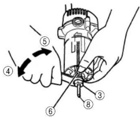
(1) Remove the base ass'y from the body. When loosening the wing nut (See Fig. 3), the base ass'y can be removed.
(2) Deeply inset the bit into the collet chuck hole. (The distance is 15 mm or more from side of collet chuck.)
(3) Depress spindle lock (Fig. 2) and rotate collet nut clockwise by hand until lock engages hole in motor spindle.
(4) While holding spindle lock engaged, tighten collet nut securely by turning clockwise using wrench provided.
CAUTIONS
○Make sure to tighten the collet chuck after inserting the bit. Collet chuck may be damaged if it is tightened without inserting the bit.
○Avoid depressing the lock pin while the bit is still in rotation. Because, there is a fear that doing so may result in an abnormal noise or damage in the fixed section of the rotating shaft.
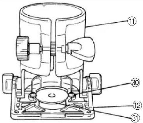
(5) Fit the removed base assembly to the rack provided on the body's outer housing after adjusting the pinion of the base assembly thereto. Then tighten the wing nut and fix the assembly securely.
2. Removal of the bit
Loosen the collet chuck in the reverse manner as described for the fitting the bit.
CAUTION
Bit is heated after the cutting work.
Do not touch it directly.
HOW TO USE
1. Adjustment of cutting depth
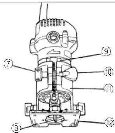
(1) Loosen the wing nut on the base ass'y.
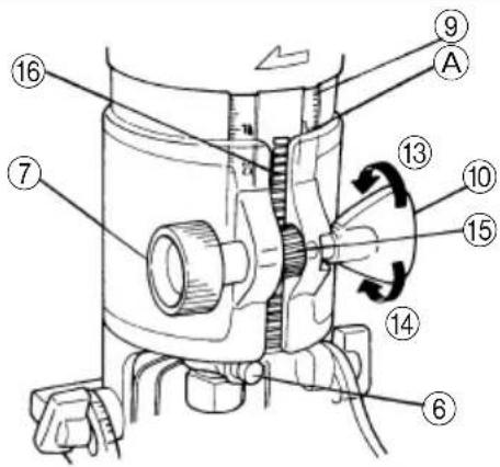
(2) Move the base ass'y up and down by turning knob bolt (A) and fit the front end of base with the pointed end of the bit. (Fig. 3)
(3) Read the value indicated by the top of the base ass'y. (A in Fig. 4)
(4) Move the base ass'y to the cutting depth.
(5) After moving the base ass'y to the cutting depth, tighten wing nut securely. (Fig. 4)
2. Cutting
It is recommended that the most appropriate guide be used which is suitable to the type of the work in order to carry out the work exactly without failure. (Refer to "How to use guide".) The material to be processed should be firmly fixed.
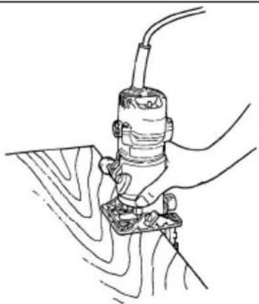
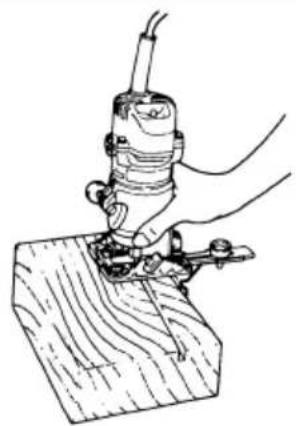
(1) Keep the bit separated from the material and hold the body firmly before switch is turned on. (Fig. 5)
(2) Feeding direction The bit rotates clockwise as seen from above. Use the unit by feeding the trimmer in the direction shown in Fig. 6. If the trimmer is fed in the reverse direction as shown in the figure, you will receive reaction of the bit and finishing of the plane to be cut becomes coarse.
3. Base angle adjustment
Loosen the right and left wing bolts and adjust the base angle. (Fig. 7) The interval of the embossed graduations is 5^ . Lay a ruler, etc., along the side of the base for use in chamfering work.
HOW TO USE GUIDE
NOTE:
Avoid tilting the base when the guide is used.
1. Trimmer guide
Application:
The guide is handy when used in processing of materials such as trimming and beveling of plywood.
(1) Fit the trimmer guide on the base with knob bolt (B).
(2) Loosen knob bolt (B) to move the trimmer guide up and down.
(3) Loosen knob bolt (C) and turn the stop screw to move the guide pin. (Fig. 8)
After moving the guide pin, tighten knob bolt (C) to secure it.
(4) When cutting refer to term "Feeding direction" in "How to use". (Fig. 9)
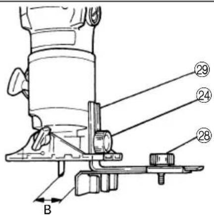
2. Straight guide
Application: It is handy when used for linear processing work such as beveling, grooving and the like.
(1) Fit the straight guide with knob bolt (B) on the base and fix it.
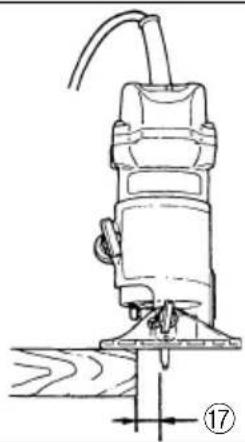
(2) Adjust the length "B" from the bit to the surface of straight guide by loosening the knob bolt (D) and roving the straight guide as necessary (Fig. 10)
(3) When cutting refer to term "Feeding direction" in "How to use". (Fig. 11)
3. Template guide
Application:
It is handy to process with a template a number of materials in one same shape.
(In this case 6 × 6 mm or 6.35 × 6.35 mm (1/4" × 1/4") straight bit is usable.)
(1) Remove the base ass'y from the main unit.
(2) Loosen the right and left wing bolts and secure the base horizontally.
(3) Install the template in the recessed part of the base and secure it with two screws.
NOTE:
Tighten the two screws moderately. Optimum tightening torque is 10-15 kg-cm.
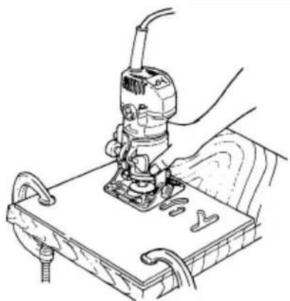
(4) Install the base ass'y in the main unit. (Fig. 13)
CAUTION
When fit the template guide, the upper part of the template guide must not touch the collet chuck.
(5) Securely fix the template to the workpiece. Feed the trimmer following the template. (Fig. 13)
Template
Template is referred to also as profilig mold and is made from a plywood or a thin wooden plate. Be careful of the following in producing a template:
When putting following the inner edge of the template, the workpiece is cut smaller because of the distance between the template guide and bit edge (with a 6 × 6 mm straight bit: 2.0 mm or 6.35 × 6.35 mm (1/4" × 1/4"): 1.8 mm). By following the outer edge of the template, the workpiece is cut larger. (Figs. 14 and 15) The thickness of the template should be 5 mm or more.
MAINTENANCE AND INSPECTION
1. Inspecting the bit
Continued use of a dull or damaged bit will result in reduced cutting efficiency and may cause overloading of the motor. Replace the bit with a new one as soon as excessive abrasion is noted.
2. Inspecting the mounting screws
Regularly inspect all mounting screws and ensure that they are properly tightened. Should any of the screws be loose, retighten them immediately. Failure to do so could result in serious hazard.
3. Maintenance of the motor
The motor unit winding is the very "heart" of the power tool. Exercise due care to ensure the winding does not become damaged and/or wet with oil or water.
4. Inspecting the carbon brushes (Fig. 16)
The motor employs carbon brushes which are consumable parts. Since an excessively worn carbon brush can result in motor trouble, replace the carbon brush with new ones having the same carbon brush No. shown in the figure when they becomes worn to or near the “wear limit”. In addition, always keep carbon brushes clean and ensure that they slide freely within the brush holders.
5. Replacing carbon brushes
Disassemble the brush caps with a slotted-head screwdriver. The carbon brushes can then be easily removed.
6. Service parts list
A: Item No.
B: Code No.
C: No. Used
D: Remarks
CAUTION
Repair, modification and inspection of HiKOKI Power Tools must be carried out by an HiKOKI Authorized Service Center.
This Parts List will be helpful if presented with the tool to the HiKOKI Authorized Service Center when requesting repair or other maintenance.
In the operation and maintenance of power tools, the safety regulations and standards prescribed in each country must be observed.
MODIFICATIONS
HiKOKI Power Tools are constantly being improved and modified to incorporate the latest technological advancements.
Accordingly, some parts (i.e. code numbers and/or design) may be changed without prior notice.
GUARANTEE
We guarantee HiKOKI Power Tools in accordance with statutory/country specific regulation. This guarantee does not cover defects or damage due to misuse, abuse, or normal wear and tear. In case of complaint, please send the Power Tool, undismantled, with the GUARANTEE CERTIFICATE found at the end of this Handling instruction, to a HiKOKI Authorized Service Center.
NOTE
Due to HiKOKI's continuing program of research and development, the specifications herein are subject to change without prior notice.
IMPORTANT
Correct connection of the plug
The wires of the main lead are coloured in accordance with the following code:
Blue: -Neutral
Brown: -Live
As the colours of the wires in the main lead of this tool may not correspond with the coloured markings identifying the terminals in your plug proceed as follows: The wire coloured blue must be connected to the terminal marked with the letter N or coloured black. The wire coloured brown must be connected to the terminal marked with the letter L or coloured red. Neither core must be connected to the earth terminal.
NOTE
This requirement is provided according to BRITISH STANDARD 2769: 1984.
Therefore, the letter code and colour code may not be applicable to other markets except The United Kingdom.
Information concerning airborne noise and vibration The measured values were determined according to EN60745 and declared in accordance with ISO 4871.
Measured A-weighted sound power level: 95 dB (A) Measured A-weighted sound pressure level: 84 dB (A) Uncertainty KpA: 3 dB (A).
Wear ear protection.
The typical weighted root mean square acceleration value: 1.0 m/s^2 .
natural_image
Line drawing of a quill pen with inkwell (no text or symbols)| English | Nederlands | ||
| GUARANTEE CERTIFICATE1Model No.2Serial No.3Date of Purchase4Customer Name and Address5Dealer Name and Address(Please stamp dealer name and address) | GARANTIEBEWIJS1Modelnummer2Serienummer3Datum van aankoop4Naam en adres van de gebruiker5Naam en adres van de handelaar(Stempel a.u.b. naam en adres vande de handelaar) | ||
| Deutsch | GARANTIESCHEIN1Modell-Nr.2Serien-Nr.3Kaufdaturn4Name und Anschrift des Kunden5Name und Anschrift des Händlers(Bitte mit Namen und Anschrift des Handlers abstempeln) | Español | |
| CERTIFICADO DE GARANTIA1Número de modelo2Número de serie3Fecha de adquisición4Nombre y dirección del cliente5Nombre y dirección del distribudor(Se ruega poner el sellú del distribudor con su nombre y dirección) | |||
| Français Português | |||
| CERTIFICAT DE GARANTIE1No. de modèle2No. de série3Date d'achat4Nom et adresse du client5Nom et adresse du revendeur(Cachet portant le nom et l'adresse du revendeur) | CERTIFICADO DE GARANTIA1Número do modelo2Número do série3Data de compra4Nome e morada do cliente5Nome e morada do distribuidor(Por favor, carímbe o nome e morada do distribuidor) | ||
| Italiano | |||
| CERTIFICATO DI GARANZIA1Modello2N° di serie3Data di acquisto4Nome e indirizzo dell'acquirente5Nome e indirizzo del rivenditore(Si prega di apporre il timbro con questi dati) | |||
HiKOKI
| 1 | |
| 2 | |
| 3 | |
| 4 | |
| 5 |
Siemensring 34, 47877 willich, Germany
Tel: +49 2154 49930
Fax: +49 2154 499350
URL: http://www.hikoki-powertools.de
Hikoki Power Tools Netherlands B.V.
Brabanthaven 11, 3433 PJ Nieuwegein, The Netherlands
Tel: +31 30 6084040
Fax: +31 30 6067266
URL: http://www.hikoki-powertools.nl
Hikoki Power Tools (U.K.) Ltd.
Precedent Drive, Rooksley, Milton Keynes, MK 13, 8PJ, United Kingdom
Tel: +44 1908 660663
Fax: +44 1908 606642
URL: http://www.hikoki-powertools.uk
Hikoki Power Tools France S.A.S.
Hikoki Power Tools Belgium N.V./S.A.
Koningin Astridlaan 51, B-1780 Wemmel, Belgium
Tel: +32 2 460 1720
Fax: +32 2 460 2542
URL http://www.hikoki-powertools.be
Hikoki Power Tools Italia S.p.A
Via Piave 35, 36077, Altavilla Vicentina (VI), Italy
Tel: +39 0444 548111
Fax: +39 0444 548110
URL: http://www.hikoki-powertools.it
Hikoki Power Tools Ibérica, S.A.
C/ Puigbarral, 26-28, Pol. Ind. Can Petit, 08227 Terrassa
(Barcelona), Spain
Tel: +34 93 735 6722
Fax: +34 93 735 7442
URL: http://www.hikoki-powertools.es


- GENERAL POWER TOOL SAFETY WARNINGS
- WARNING
- Save all warnings and instructions for future reference.
- 1) Work area safety
- 2) Electrical safety
- 3) Personal safety
- 4) Power tool use and care
- 5) Service
- PRECAUTION
- PRECAUTIONS ON USING TRIMMER
- STANDARD ACCESSORIES
- APPLICATIONS
- PRIOR TO OPERATION
- Power source
- Power switch
- Extension cord
- Fitting the bit
- Cutting using the workpiece edge as a base line (Fig. 1)
- Confirm the spindle lock mechanism.
- FITTING AND REMOVAL OF THE BIT
- Fitting the bit
- CAUTIONS
- Removal of the bit
- CAUTION
- HOW TO USE
- Adjustment of cutting depth
- Cutting
- Base angle adjustment
- HOW TO USE GUIDE
- NOTE:
- Trimmer guide
- Straight guide
- Template guide
- Template
- MAINTENANCE AND INSPECTION
- Inspecting the bit
- Inspecting the mounting screws
- Maintenance of the motor
- Inspecting the carbon brushes (Fig. 16)
- Replacing carbon brushes
- Service parts list
- MODIFICATIONS
- GUARANTEE
- NOTE
- IMPORTANT
- Correct connection of the plug
- HiKOKI
- Hikoki Power Tools Netherlands B.V.
- Hikoki Power Tools (U.K.) Ltd.
- Hikoki Power Tools France S.A.S.
- Hikoki Power Tools Belgium N.V./S.A.
- Hikoki Power Tools Italia S.p.A
- Hikoki Power Tools Ibérica, S.A.
Brand : HiKOKI
Model : M6SB
Category : String Trimmer