FX 3-A - Welding machine HILTI - Free user manual and instructions
Find the device manual for free FX 3-A HILTI in PDF.
| Product type | Cordless stud welding unit (drawn arc welding) |
| Brand | Hilti |
| Model | FX 3-A |
| Dimensions (L x W x H) | 434 mm x 160 mm x 393 mm |
| Weight | 12 kg |
| Power supply | Integrated Li-Ion battery, 52.8 V (nominal), 7.5 Ah / 396 Wh |
| Recommended charger | Hilti C 53 (C 53 series) |
| Charging time (80 %) | 30 min in fast charge, 50 min in normal charge |
| Typical runtime | 250 to 1,200 welding operations (depending on stud) |
| Shielding gas | FX 3-GC cartridge (max. pressure 168 bar) |
| Operating temperature | -20 °C to +40 °C |
| Protection class | IP 23 |
| EMC classification | Emission class A |
| Welding technology | Cordless Stud Fusion (CSF) – automated drawn arc welding |
| Main functions | Active Fusion Indicator (AFI), automatic shut-off after 60 min of inactivity, deep discharge protection |
| Displays | Screen, battery charge indicators, gas level, maintenance, errors |
| Routine maintenance | Clean air filter every 2 months, check stud holder, shielding ring and brass ring regularly |
| Wear parts | Stud holder (X-SH F3), shielding ring (X-SR F3), surface treatment tool (FX 3-ST) |
| Cleaning | Slightly damp cloth, soft brush for ventilation slots |
| Warranty | Manufacturer's warranty – contact local Hilti partner |
| Included accessories | Cordless welding unit, instruction manual (hand-held unit and cables sold separately) |
Frequently Asked Questions - FX 3-A HILTI
User questions about FX 3-A HILTI
0 question about this device. Answer the ones you know or ask your own.
Ask a new question about this device
Download the instructions for your Welding machine in PDF format for free! Find your manual FX 3-A - HILTI and take your electronic device back in hand. On this page are published all the documents necessary for the use of your device. FX 3-A by HILTI.
USER MANUAL FX 3-A HILTI
text_image
Diagram of a portable electronic device with numbered labels pointing to ports and buttons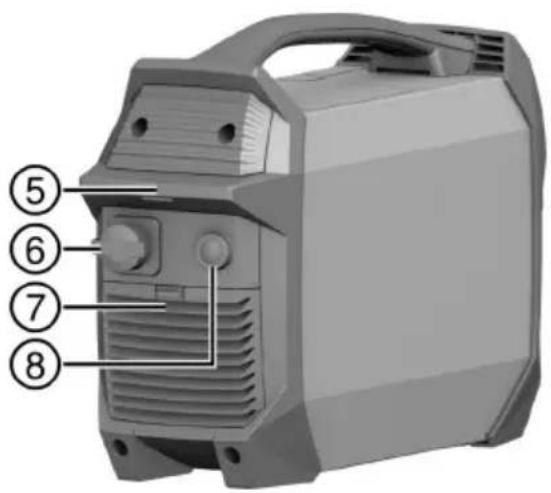
text_image
Diagram of a portable air conditioner unit with numbered labels pointing to key components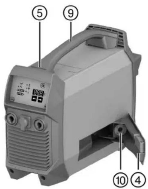
text_image
Labeled diagram of a portable air purifier device with numbered parts and control panel
text_image
Diagram of a device control panel with numbered labels pointing to various function keys and buttons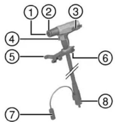
text_image
Labeled diagram of a mechanical device with numbered parts for identification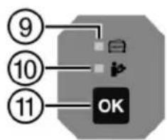
flowchart
graph TD
    A["9"] --> B["OK"]
    C["10"] --> B
    D["11"] --> B

4
natural_image
Exterior view of a portable electronic device with control panel and buttons (no visible text or symbols)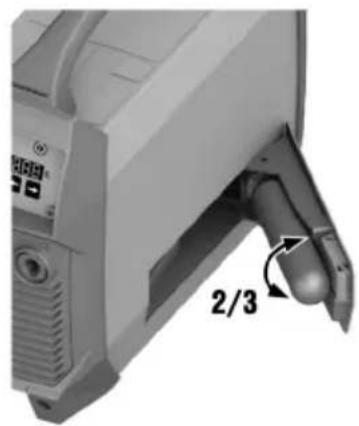
natural_image
Close-up of a computer monitor with a dial indicator and 2/3 label, showing no readable text or symbols beyond the label.5
natural_image
Mechanical device with a cylindrical component and a 1/5 rotational arrow indicator (no text or symbols on the device itself)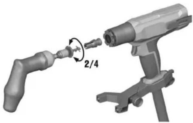
natural_image
3D illustration of a mechanical device with a 2/4 ratio adjustment arrow (no text or symbols on the diagram itself)6

natural_image
Close-up of a handheld industrial device with a pipe and connector, no visible text or symbols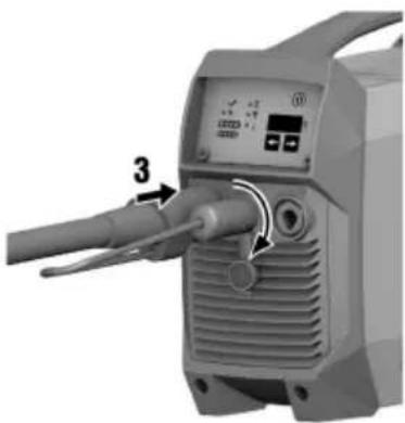
natural_image
Close-up of a handheld industrial device with a labeled component (3) and control panel, no visible text or symbols beyond the number.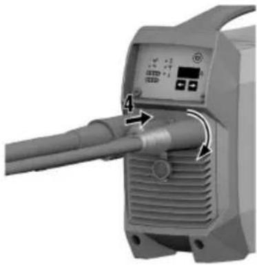
natural_image
Close-up of a mechanical device with a pipe and control panel, no visible text or symbols7

text_image
直径: 300mm x 2740mm F1 3-57 d14FX 3-ST d14

natural_image
Close-up of a metallic cutting tool with no visible text or markingsFX 3-ST d20
12

natural_image
3D rendered mechanical component with a droplet falling into a circular hole and an eye symbol with an exclamation mark (no text or labels)
natural_image
Close-up of a mechanical component with a cylindrical shaft and base, no visible text or symbols13

natural_image
Illustration of a hand using a tool to press or install a mechanical component, with 90-degree angle annotations (no text or symbols on the diagram itself)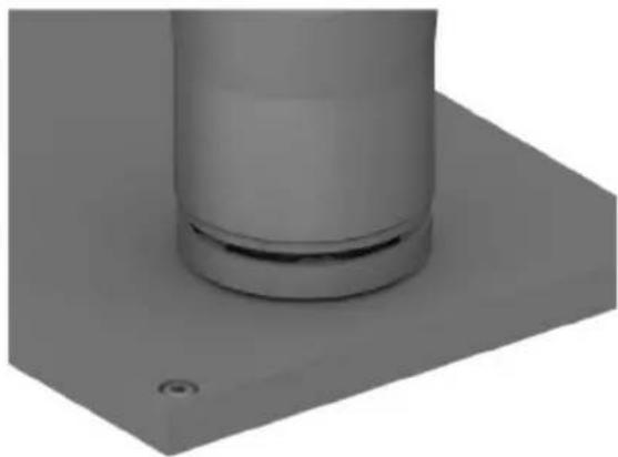
natural_image
3D rendered mechanical component with a cylindrical shaft and mounting base (no text or symbols visible)14

text_image
1/5 2/4 315

natural_image
3D rendered mechanical component with a V-shaped cutout and a checkmark symbol (no text or labels)
natural_image
3D rendered mechanical component with no visible text or symbols, featuring a circular symbol with a prohibition sign (no text or labels)16

natural_image
3D rendered image of a gray washer with a circular hole and a black checkmark (no text or symbols)
natural_image
3D rendered gray circular ring with a central hole and a prohibition symbol (no text or labels)17
natural_image
3D rendered mechanical component with perforated circular opening and a checkmark symbol (no text or labels)
natural_image
3D rendered mechanical component with perforated circular opening and no visible text or symbolsFX 3-A
en Original operating instructions . . . . . . . . . . . . . . . . . . . . . . . . . . . . . .
Original operating instructions
1 Information about the operating instructions
1.1 About these operating instructions
- Read these operating instructions before the product is used or operated for the first time. This is a prerequisite for safe, trouble-free handling and use of the product.
- Observe the safety instructions and warnings in these operating instructions and on the product.
• Always keep the operating instructions with the product and make sure that the product is accompanied by these operating instructions only, when the product is given to other persons.
1.2 Explanation of symbols
1.2.1 Warnings
Warnings alert persons to hazards that occur when handling or using the product. The following signal words are used:

DANGER
DANGER !
- Draws attention to imminent danger that will lead to serious personal injury or fatality.

WARNING
WARNING!
- Draws attention to a potential threat of danger that can lead to serious injury or fatality.

CAUTION
CAUTION !
- Draws attention to a potentially dangerous situation that could lead to personal injury or damage to the equipment or other property.
1.2.2 Symbols in the operating instructions
The following symbols are used in these operating instructions:

Comply with the operating instructions

Instructions for use and other useful information

Dealing with recyclable materials

Do not dispose of electric equipment and batteries as household waste

Hilti Li-ion battery

Hilti charger
1.2.3 Symbols in illustrations
The following symbols are used in illustrations:

These numbers refer to the illustrations at the beginning of these operating instructions.
3
The numbering reflects the sequence of operations shown in the illustrations and may deviate from the steps described in the text.

Item reference numbers are used in the overview illustration and refer to the numbers used in the key in the product overview section.

This symbol is intended to draw your special attention to certain points for handling the product.
1.3 Product-dependent symbols
1.3.1 General symbols
Symbols used in relation to the product.
 | The power tool supports near-field communication (NFC) technology, which is compatible with iOS and Android platforms. |
 | Direct current (DC) |
 | General warning symbol |
 | If applied on the product, the product has been certified by this certification body for the US and Canadian markets according to the applicable standards. |
1.3.2 Obligation symbols
Mandatory actions
 | Read the operating instructions |
 | Wear protective gloves |
 | Wear hearing protection |
 | Wear eye protection |
1.3.3 Warning signs
Hazard warning
 | Warning: Non-ionizing radiation |
 | Warning: Magnetic field |
 | Warning: Electric voltage |
 | Warning: Flammable substances |
 | Warning: hot surface |
1.4 Product information
Hilti products are designed for professional use and may be operated, serviced and maintained only by trained, authorized personnel. This personnel must be specifically informed about the possible hazards. The product and its ancillary equipment can present hazards if used incorrectly by untrained personnel or if used not in accordance with the intended use.
The type designation and serial number are printed on the rating plate.
Write down the serial number in the table below. You will be required to state the product details when contacting Hilti Service or your local Hilti organization to inquire about the product.
Product information
| Stud welding machine FX 3-A | |
| Generation 01 | |
| Serial no. |
2.1 Safety instructions
WARNING Study all safety instructions and other instructions, images and technical data with which this power tool is provided. Failure to observe the instructions below can result in electric shock, fire and/or serious injury.
Keep all safety instructions and instructions for future reference.
Read all operating instructions and other documents about all the system components used.
Work area safety
▶ Make sure that the work area is well ventilated.
- Keep your work area clean and well lit. Cluttered or dark work areas invite accidents.
- Keep the work area and the surrounding air free from dust and other substances such as corrosive gases.
- Set the product on a smooth, horizontal surface or implement suitable measures to prevent the product from tipping over.
- Keep children and other persons clear when the product is in use.
Electrical safety
An electric shock can be life-threatening or even fatal. Do not touch live parts inside or outside the product.
▶ Check that all connectors and connections are secure and replace damaged leads before use. All leads and lines must be securely connected, undamaged and insulated.
- Disconnect the connection between product and charger and switch the product off before carrying out cleaning and maintenance work.
- Avoid body contact with earthed or grounded surfaces such as pipes, radiators, cookers, stoves and refrigerators.
Personal safety
Stay alert, watch what you are doing and use common sense when operating a power tool. Do not use a power tool while you are tired or under the influence of drugs, alcohol or medication. A moment of inattention while operating the power tool may result in serious personal injury.
- Wear personal protective equipment consisting of protective clothing covering the entire body, protective gloves, safety footwear, hearing protection and protective eyewear with side shield providing protection against UV radiation, heat and flying sparks.
When the product is in use, the arc radiation can be harmful to the eyes and to the skin. Wear personal protective equipment. Do not look directly into the welding arc. Comply with national, local and jobsite-specific health and safety requirements.
On account of the welding current there is a risk of electric shock. Keep the distance between the stud to be welded and the ground connection as short as possible and check that the ground clamp has a secure connection to the workpiece.
- When the product is in use welding fumes and other gases harmful to health are produced. To reduce the production of gases harmful to health, in all steps of the procedure follow the directions in these operating instructions. Make sure that the work area is well ventilated. Comply with national, local and jobsite-specific health and safety requirements.
- Do not weld on surfaces that are contaminated with oil or other flammable materials. Vapors such as solvent vapors are flammable and can cause burns.
The front, metallic part of the hand tool becomes hot in use and can cause burns. Do not touch this area before the hand tool has cooled down completely.
Using and handling the product
Do not expose the product to rain or moisture. Penetrating moisture can cause short circuits, electrical shock, burns or explosions.
- Flying sparks can start fires and cause explosions. Sparks and hot pieces of metal can also pass through small cracks and openings and make their way into other areas. Never use the product in the immediate vicinity of flammable materials. If this is not possible, use a suitable cover. Comply with national, local and jobsite-specific health and safety requirements.
Do not use the welding machine where there is a risk of fire or explosion, on closed tanks, drums and pipes. Before welding the materials stated above, prepare them in accordance with the national and international standards. Comply with national, local and jobsite-specific health and safety requirements.
- Inert-gas cans contain pressurized gas and can explode if damaged. Protect inert-gas cans from excessive heat, mechanical damage, scale, naked flame, sparks and electric arcs. Follow the manufacturer's specifications and national and international regulations for inert-gas cans and accessories. Dispose of inert-gas cans only when they are completely empty.
HILTI
▶ Use the product and accessories only when they are in perfect working order.
▶ Never tamper with or modify the product or accessories in any way.
▶ Check that moving parts operate satisfactorily and do not jam, and make sure that no parts are broken or damaged in such a way that the product might no longer function correctly.
Before you switch the product on, make sure that no-one is going to be put at risk.
To allow sufficient cooling air to enter and exit, when setting up the equipment make sure that it has 50 cm (20 in) of clear space all round.
▶ Never use the welding machine on pressurized gas containers.
An inert-gas can that is not correctly connected or that is damaged is a potential hazard. Check the connection of the inert-gas can before use and dispose of damaged inert-gas cans in accordance with your local regulations.
- Do not charge or continue to use a damaged welding machine (for example cracks, broken parts, contacts bent, pushed in or pulled out).
▶ Do not use damaged accessories or studs.
- Switch the product off before changing accessories or setting the product aside.
Electric and Magnetic Fields (EMF)
Electric current flowing through any conductor causes localized Electric and Magnetic Fields (EMF). Welding current creates EMF fields around welding cables and welding machines. EMF may interfere with pacemakers, hearing aids and other sensitive medical devices. Users and persons working in the near vicinity of the welding machine, cables and user should consult their physician before working with or in the near vicinity of this welding machine. Exposure to EMF in welding may have other health effects which are now not known. The user and all persons in the near vicinity should do the following to minimize exposure to EMF fields during welding:
- Bundle the lines of the hand tool and the ground cable and secure all lines with adhesive tape.
- Do not place your body between the electrode and the ground cable. If the electrode is on your right side, the ground cable should also be on your right side.
- Never sling, wrap, or coil the lines around your torso or any body part.
- Keep lines away from head and torso.
- Connect the ground cable to the workpiece as described in these instructions.
- Do not work in the immediate vicinity of the welding machine.
EMF emissions may interfere with surrounding sensitive equipment, including but not limited to:
• Network, signal and data-transmission lines
• Data-processing and telecommunications equipment
• Measurement and calibration equipment
It is the operator's and user's obligation to implement appropriate measures to check, assess, and if necessary, rectify interferences with equipment in the vicinity of the welding machine and application point(s) in accordance with international, national, local, or jobsite regulations.
Service
▶ Have your product repaired only by Hilti Service and only with genuine Hilti spare parts. The safety of the product can thus be maintained.
▶ Stud welding might require additional quality measures according to international and local regulation. Hilti will provide guidance on Welding Procedure Specification, Welding Procedure Qualification Record and on Factory Process Control in accordance with international regulation. If you require further support, consult Hilti Service.
2.2 Careful handling and use of cordless welding machines
- Comply with the following safety instructions for the safe handling and use of products with Li-ion batteries. Failure to comply can lead to skin irritation, severe corrosive injury, chemical burns, fire and/or explosion.
▶ Use only the Hilti C 53 charger to charge the welding machine. There is a risk of fire if any other charger is used.
▶ Follow the charging instructions in these operating instructions and in the operating instructions of the charger. Do not charge the product outside the stated temperature range. Incorrect charging or charging at temperatures outside the defined range can damage the battery or increase the risk of fire.
▶ Make sure that the product is switched off when it is not in use. Keep the product well away from other metallic objects such as paper-clips, coins, keys, nails and other small metallic objects that could create a conductive bridge from one connection to the other. Short-circuiting connections can cause burns or fires.
- Misuse can result in battery fluid escaping from the product. Avoid contact with this liquid. If contact accidentally occurs, rinse with water. Seek medical attention if the liquid comes into contact with the eyes. Liquid escaping from the battery can cause skin irritation or burns.
▶ Treat the product with care in order to avoid damage and prevent leakage of fluids that are extremely harmful to health!
Do not use a damaged or modified welding machine. Damaged or modified components and products can exhibit unpredictable behavior that can lead to explosions or risk of injury.
- Do not disassemble, squash or incinerate the product and the installed battery, do not subject them to temperatures above 80 °C (176 °F) or burn them. Fire or temperatures above 130 °C (265 °F) can lead to an explosion.
▶ Never expose the product to the direct rays of the sun, elevated temperature, sparking, or open flame. This can lead to explosions.
If the product is too hot to touch, it may be defective. Put the product in a place where it is clearly visible and where there is no risk of fire, at an adequate distance from flammable materials. Allow the product to cool down. If the product is still too hot to touch after an hour, it is faulty. Consult Hilti Service or read the document entitled "Instructions on safety and use for Hilti Li-ion batteries".

Observe the special guidelines applicable to the transport, storage and use of lithium-ion batteries. → page 15
Read the instructions on safety and use of Hilti Li-ion batteries that you can access by scanning the QR code at the end of these operating instructions.
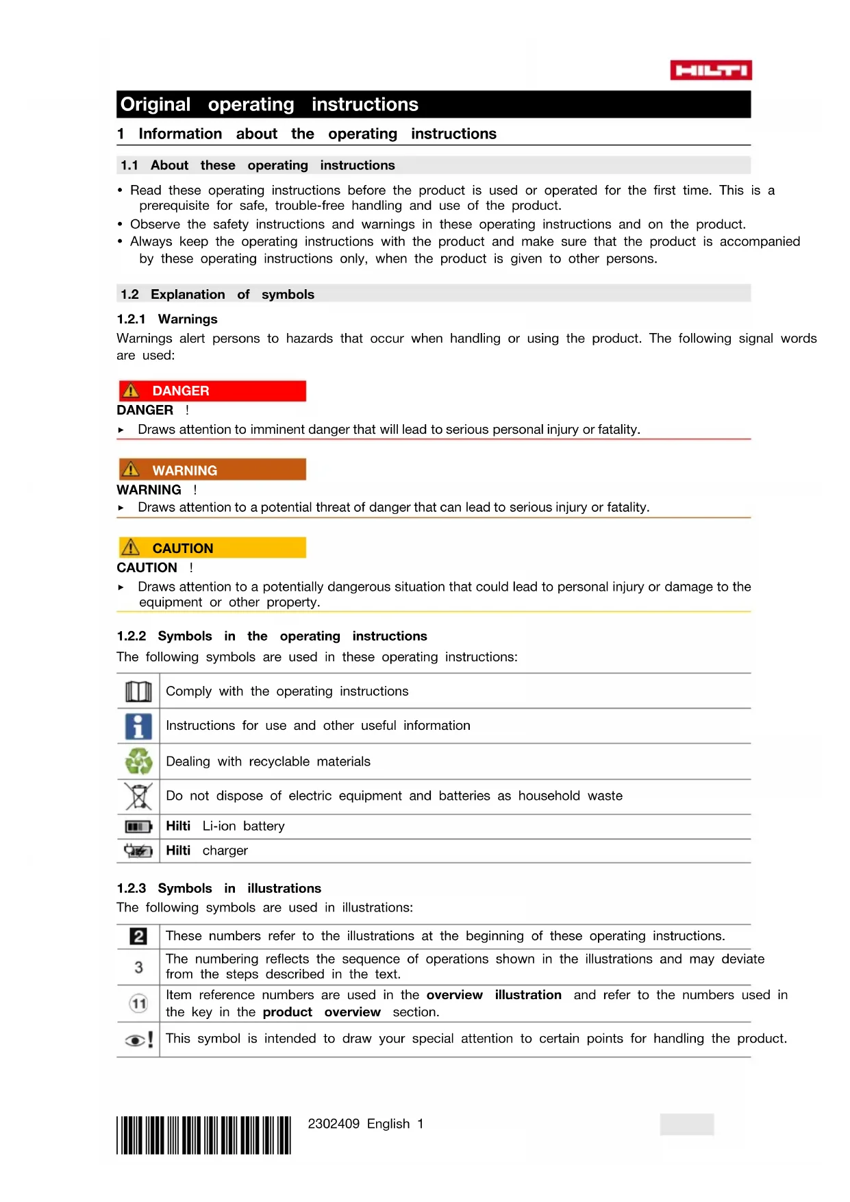
3 Description
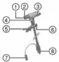
3.1 Product overview, welding machin

text_image
Technical diagram of a portable electronic device with numbered parts and labeled internal components① Current socket (-) for current connector of the hand tool
② Control-line connection
③ Current socket (+) for ground lead
④ Cover, inert-gas can
⑤ Eye for attaching the shoulder strap
⑥ Charger connection
⑦ Air-filter flap
⑧ Blanking cover (no function)
⑨ Grip
⑩ Connection for inert-gas can
⑪ Operating status indicator
⑫ Process-fault indicator
⑬ Display
⑭ On/off button
⑮ Adjuster button, right
⑯ Adjuster button, left
⑰ Temperature-fault indicator
⑱ Hand-tool fault indicator
⑲ Gas-level indicator
⑳ Battery state of charge indicator
②1 Service indicator
3.2 Product overview, hand too
text_image
Labeled diagram of a mechanical or electrical component with numbered parts 1 through 8
① Stud holder
② Shielding ring
③ Belt hook
④ Trigger
⑤ Support leg
⑥ Eye for attaching the tool tether
⑦ Control connector
⑧ Current connector (-)
⑨ AFI (Active Fusion Indicator)
⑩ Fault indicator
⑪ OK button
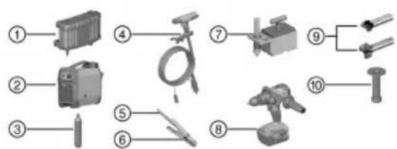
3.3 Overview, system components
text_image
Labeled diagram of various electrical components and tools, numbered 1 to 10① C 53 charger
② Welding machine FX 3-A
③ Inert-gas can FX 3-GC
④ FX 3-HT hand tool, with lines
⑤ Ground lead
⑥ Cable clamp
⑦ Magnetic foot
⑧ Cordless drill / driver Hilti SF 6-A22
⑨ Surfacing tool
⑩ Setting tool for sealing washer
3.4 Intended use
The product described is a cordless stud welding machine. It is designed for welding F-BT studs to steel on the principle of drawn-arc welding.
- Use only Hilti chargers of the C 53 series. More information is available from your Hilti Store or from www.hilti.group
- Observe the operating instructions and other documents for the studs, the inert-gas can and all other system components used.
3.5 Cordless Stud Fusion technology
The Cordless Stud Fusion (CSF) technology is based on the principle of stud welding by drawn arc. This welding process consists of several phases. The sequencing of the individual welding phases is fully automated and requires no additional control intervention by the user.
The five phases of the welding operation:
- In the first phase, the inert-gas atmosphere is created. Inert gas flows to the front part of the hand tool, where it displaces the atmospheric air.
- Current flows through the stud to the base metal, while at the same time the stud is lifted in a controlled movement until there is a gap of defined size between it and the base metal. This produces a stable pilot arc, initially of low power. In this phase there is no appreciable melting of stud or base metal.
- The power of the arc is surged to maximum, with current flux now automatically increased to the target value. The power of the arc is now sufficient to melt the tip of the stud and the base metal.
- Welding is completed by the system. The stud is moved toward the base metal. Molten material from base metal and stud mix.
- The stud is briefly held in this position and the molten metal hardens. More inert gas flows round the weld, protecting against oxidation.
3.6 AFI (Active Fusion Indicator)
The welding machine assists the user in carrying out the welding process correctly, increasing the achievable quality of the weld. The achievable quality of a weld depends on many influencing factors.
Certain process deviations from the expected sequence can be detected and brought to the attention of the user. No assessment of weld quality is made by this process analysis. It is not possible to detect all faults.
This process analysis is not a substitute for diligence and quality control on the part of the If an irregularity is detected, always check the fault indicator on the welding machine and consult the Troubleshooting → page 15 section.
| Indicator System ready for use | Hand tool with stud inserted pressed against base metal, ready for triggering | During the welding operation | Welding operation completed, no irregularities | Welding operation completed, irregularities detected | |
| Hand tool | AFI Green light | Green light | Green light | Off Off | Off |
| Fault indicator | Off Green light | Green light | Off Flashing red light | Off | |
| Welding machine | Operating status indicator | Green light | Green light | Green light | Off |
| Service indicator | Off Off Off | Off Off | |||
| Process-fault indicator | Off Off Off | Off Flashing | red light | ||
| Hand-tool fault indicator | Off Off Off | Off Off | |||
| Temperature indicator | Off Off Off | Off Off |
3.7 Battery protection function
The product has a battery protection function to protect the battery against deep discharge. The battery protection function warns the user when battery charge state is too low and switches the product off after 3 minutes.
Indicators
| Indicator Meaning | |
| Battery is discharged | |
| ‘F.02’ Battery discharged - the deep discharge prevention system has tripped. | |
3.8 Automatic power-off
The product has an automatic shutdown to extend the battery's operating time. The product shuts down automatically if 60 minutes pass without a welding operation taking place.
3.9 Indicators for gas fill level and battery,
| Indicator Meaning Indicator Meaning | |||
 | Inert-gas can full Battery fully ch |  | |
 | Inert-gas can 75 % full |  | Battery 75 % full |
 | Inert-gas can 50 % full |  | Battery 50 % full |
 | Inert-gas can 25 % full |  | Battery 25 % full |
 | Inert-gas can empty |  | Battery is discharged |
| Fault indicator shows simultaneously ‘F.05’ | Fault indicator shows simultaneously ‘F.02’ | ||
3.10 Items supplied
Cordless welding machine, operating instructions
Other system products approved for use with this product can be found at your local Hilti Store or at: www.hilti.group
4 Technical data
4.1 Welding machine
| Battery nominal voltage | 52.8 V | |
| No-load voltage | 58 V | |
| Charging current | 10 A | |
| Charging current, fast charge | 18 A | |
| Battery capacity | 7.5 Ah / 396 Wh | |
| Battery type | Li-ion | |
| Typical charging time on fast charge (to 80 % battery capacity) | 50 min | |
| Typical charging time (to 80 % battery capacity) | ||
| Typical range with full battery charge, depending size | 250 stud 200 welding operations | |
| EMC classification | Emissions class A | |
| Dangerous goods class | 9 | |
| Classification code | M4 | |
| Packaging group | II | |
| Cooling | AF | |
| Degree of protection | IP 23 | |
| Dimensions (L x W x H) | 434 mm x 160 mm x 393 mm(17.1 in x 6.3 in x 15.5 in) | |
| Weight | 12 kg(26 lb) | |
| Maximum relative humidity during operation | 20 °C (68 °F) | 90 % |
| 40 °C (104 °F) | 50 % | |
| Ambient temperature for operation | -20 °C ... 40 °C(-4 °F ... 104 °F) | |
| Temperature of welding machine / hand tool during operation | 6 per-40 °C(41 °F ... 104 °F) | |
| Temperature of workpiece / stud | 0 °C ... 40 °C(32 °F ... 104 °F) | |
| Storage temperature | -20 °C ... 50 °C(-4 °F ... 122 °F) | |
| Temperature of welding machine at start of charging | °C ... 40 °C(39 °F ... 104 °F) | |
| Maximum pressure of the inert gas | 168 bar(2,440 psi) | |
| Storage temperature, inert-gas can | -20 °C ... 50 °C(-4 °F ... 122 °F) | |
5 Preparations at the workplace
▶ Check all components for damage and replace damaged components.
Before use, make sure that the ground clamp and the stud holder are free of contaminants.
5.1 Setting up the product
Set-up conditions for charging and in operation
- Do not cover up the product. Air must be able to flow unhindered through the air vents at front and rear.
- To prevent product damage due to insufficient air supply, make sure that there is a clear space of 0.5m (2 ft) all round the product.
- Make sure that the fan does not induct metallic dust (e.g. from grinding work).
- The surface on which the product is set must be smooth and level, so that the product does not tip over or fall.
5.2 Charging cordless welding machine
Fully charge the product before using it for the first time.

Over a long period of non-use, charge the product regularly every 6 months to prevent deep discharge.
- Charge the product as described in the operating instructions of the Hilti C 53 charger.

You can resume operation of the product when the battery has charged to ≥25% capacity.
5.3 Changing inert-gas can

CAUTION
Risk of injury by gas escaping during gas can replacement. Hearing damage.
▶ Wear hearing protection.

CAUTION
Risk of damage to the seal due to flash-chilling. Escaping inert gas has the effect of flash-chilling the seal on the gas can connection. The chilled seal can be damaged and consequently leak.
▶ Unscrew the used gas can from the connection slowly.
- Wait at least 2 minutes before inserting a new gas can.
Change the inert-gas can when it is empty. See the section headed Indicators for gas fill level and battery → page 7.

Comply with the safety data sheet of the inert-gas can.
- Open the cover.
- Fully unscrew the inert-gas can counter-clockwise from the connection.
In this process, residual gas escapes from the inert-gas can with a loud hiss.
- Screw the new inert-gas can clockwise into the connection and tighten the can hand-tight.
Materials
Inert-gas can FX 3-GC
- Close the cover.
The action of closing the cover pierces the inert-gas can.
5.4 Installing / changing stud holder 5

WARNING
Risk of injury by stud holder! The stud holder gets hot in use.
▶ To avoid burns, wait until the stud holder has cooled down.
▶ Wear protective gloves when changing the stud holder.
- Make sure that the welding machine is switched off. → page 12
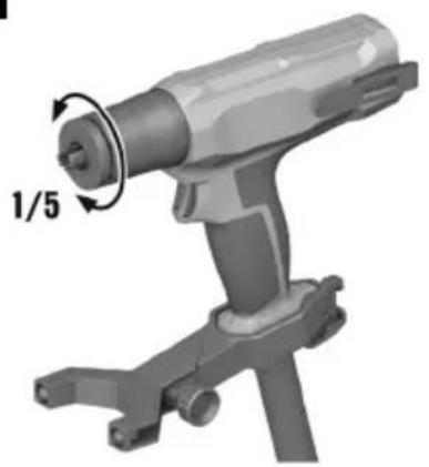
- Twist the shielding ring counter-clockwise by hand and remove it from the hand tool.
- If a stud holder is installed, use the following tools to unscrew the stud holder counter-clockwise to remove it from the hand tool:
| Materials |
| S-BT 1/4" torque screwdriver - 5 Nm |
| X-SHT F3 accessory tool for stud change |
▶ To avoid damage, insert the accessory tool fully into the stud holder.
▶ To avoid damage, do not use any tool other than the recommended torque screwdriver.

Replace the shielding ring and/or stud holder if worn. → page 14
- Screw the stud holder you need into the hand tool, tightening the stud holder clockwise to the specified tightening torque. When the required tightening torque is reached the torque screwdriver disengages with haptic and acoustic feedback.
| Technical data | |
| Tightening torque for stud holder 5 Nm | (4 ftlb) |
| Materials | |
| S-BT 1/4" torque screwdriver - 5 Nm | |

For more information on the stud holders, consult the operating instructions that accompany the studs.
- Set the shielding ring on the bayonet connector on the hand tool and twist it clockwise until it engages.
5.5 Connecting hand tool and ground I ad 6

CAUTION
Risk of damage due to incorrect connecting sequence.
▶ To prevent damage, make the connections in the correct sequence.
- Make sure that the welding machine is switched off.
- Connect the current connector of the hand tool to the minus current socket and latch it in position by turning it clockwise.
- Connect the control connector of the hand tool to the welding machine and latch it in position by turning it clockwise.
-
Connect the connector of the ground cable to the plus current socket and latch it in position by turning it clockwise.
-
Check that all connections are fully latched.

The hose of the hand tool must be filled with inert gas before work starts.

When you disconnect the hose package after use, fit the protective caps on to the connections after disconnecting.
5.6 Preparing workpiece and connecting ground clamp 7, 8

WARNING
Risk of injury by dusts that are hazardous to health! Dust from surface coating and metal can be hazardous to health.
▶ Depending on the type of coating to be removed, wear a dust mask or respiratory protection, as necessary.
- Comply with the locally applicable regulations for occupational health and safety.

CAUTION
Risk of corrosion due to inadequate corrosion protection! Surfacing can expose the workpiece to corrosion.
▶ Establish corrosion protection in accordance with your national and local requirements and in accordance with jobsite specifications.
Hilti offers a sealing washer in combination with the F-BT-MR SN stud. The prepared surface and the stud are protected against corrosion by the sealing washer. Check usability in accordance with your national and local requirements and in accordance with jobsite specifications. For more information contact Hilti Service.
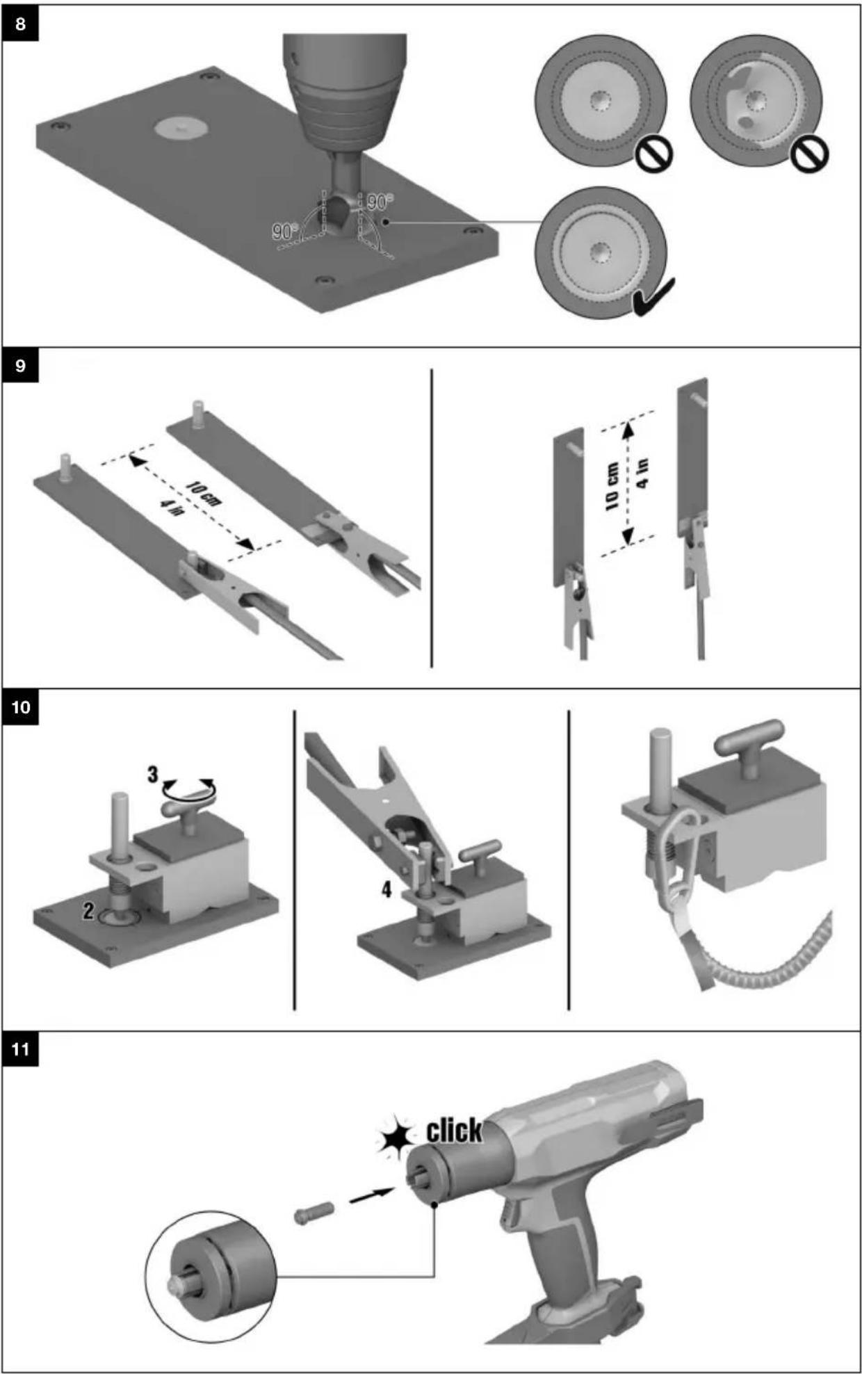
- Use a center punch to mark the position where the stud is to be welded on.
- Comply with the minimum distances between studs and from edges.
- Select the appropriate surfacing tool for working on the surface to be prepared.
Materials
FX 3-ST d14 surfacing tool for the following base metals:
- uncoated carbon steel
- weldable primer on steel, coat thickness up to 25 µm
FX 3-ST d20 surfacing tool for the following base metals:
- non-weldable primer on steel
- weldable primer on steel, coat thickness 25 µm and thicker
- galvanized steel
- duplex-coated steel
- multi-coated steel
Maximum coating thickness 1 mm

WARNING
Hazard due to inadequate surface preparation. If the surface was inadequately prepared, a subsequent weld is substandard and the stud's load-bearing ability is reduced!
▶ Weld the stud within 2 hours after surface preparation.
Before every welding operation, always check that the surface is correctly prepared.
- Remove the coating with the surfacing tool. Apply firm contact pressure to the drill / driver.
Technical data
| Contact pressure | ≥ 20 kg(≥ 44 lb) |
Materials
| Hilti SF 6-A22 drill / driver, 2nd gear, speed 2000 rpm, "Drilling" setting |
HILTI
The surface and the ring produced around the prepared area must be free of all traces of coating material and/or contaminant. Remove all residues and contaminants caused by the surfacing operation.

Comply with the operating instructions of the drill / driver.

As a general rule, the tool-specific operating instructions of the cordless drill / drivers apply. In this special application for surface preparation with the surfacing tools in the FX 3-A system, the drill / driver can also be held with the other hand at the back of the drill / driver.
5.7 Connecting ground clamp 9
- Connect the ground clamp to an uninsulated point on the workpiece or to a stud welded beforehand. Comply with the requirement for minimum spacing between the stud to be welded and the ground clamp. When welding on walls, always position the ground clamp below the weld position.
| Technical data | |
| Minimum distance between the stud to be welded and ground clamp | the0 cm(4 in) |

If the workpiece is coated or offers no uninsulated point for connection of the ground clamp, use the magnetic foot on a surface prepared beforehand. → page 12
5.7.1 Positioning magnetic foc
Position the magnetic foot for the first stud only. For all subsequent studs, connect the ground clamp to a stud welded on beforehand.
- To create an uninsulated point on the workpiece, prepare the workpiece in the same way as for welding a stud. → page 11

Ideally, this means preparing the workpiece at a point where a stud is going to be welded into place later on.
- Position the magnetic foot in such a way that the contact pin touches the center of the prepared area.
- Activate the magnetic foot by turning the grip. Check that it holds securely.
- Position the ground clamp on the contact pin of the magnetic foot.

Deactivate the magnetic foot before removing it.
- If the following conditions are met, also take this action:
Conditions: Working at height
As drop arrester for the magnetic foot, use only the Hilti tool tether #2261970.
▶ Use a carabiner engaged in the eye of the magnetic foot to secure the tool tether as shown in the illustration. Check that it holds securely.
- Secure the second carabiner to a load-bearing structure. Check that the carabiner holds securely.

Comply with the operating instructions of the Hilti tool tether.
6 Operation
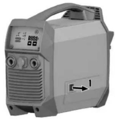
6.1 Switching on / off
- To switch the welding machine on, press the on/off button and hold it down for at least 2 seconds.
- To switch the welding machine off, press the on/off button and hold it down for at least 2 seconds.
▶ All indicators on the welding machine go out.
6.2 Selecting H code
▶ Use the right/left buttons to select the H code that matches the stud to be used.

The matching H code is to be found on the head of the stud and in the corresponding operating instructions.
6.3 Welding stud 1, 2, 13
- Fill the hose of the hand tool with insert gas. To achieve this, press the trigger for at least 1 second without touching the hand tool against the workpiece.
▶ After 1 second the system starts purging with inert gas by flooding inert gas into the hose for 1.5 seconds.
-
Make sure that the stud is completely free of contaminants of all kinds.
-
Insert the appropriate stud completely into the stud holder designed for it until the stud engages.
▶ Follow the operating instructions for the stud!

If you insert a wrong stud into the stud holder by mistake, you can carefully remove the stud from the stud holder with a pair of flat-nosed pliers.
Be sure not to damage the stud holder in this process and subsequently dispose of the stud.
-
Position the hand tool on the prepared surface of the workpiece such that the stud tip is positioned in the center of the prepared surface. The stud tip and the centering recess made with a center punch are of assistance in positioning.
-
Using both hands, press the hand tool perpendicular against the workpiece and hold it steady in this position throughout the entire operation.
▶ Do not cover up the indicator on the hand tool.
▶ Use the support leg to make the perpendicular position easier to maintain.
- Fully depress the trigger for at least 0.5 of a second.
▶ Inert gas flows for about 1 second before the welding operation starts.
▶ The welding operation then takes place.
▶ After the end of the welding operation the inert gas flows on for approx. 1 second.

Do not lift the hand tool off the workpiece until the indicators indicate that the welding operation has completed. → page 6
- When the welding operation has completed, use both hands to lift the hand tool in a fluid movement vertically off the stud.
▶ Pulling the hand tool off at an angle will cause sustained damage to the stud holder.
WARNING
Hazard due to faulty weld! If the surface was inadequately prepared, the welding operation was not completed correctly or some other fault is present, the stud's load-bearing ability is reduced.
▶ Fault indications during and/or after the welding operation, severe smoke formation and/or a black ring on the surface round the stud are signs that the stud has not been welded correctly.
-
Check the indicators of the welding machine and the hand tool for indications of a fault. Check the stud and the workpiece for faults.
-
Comply with the operating instructions of the stud used in order to check the stud.
In the event of a fault, consult the AFI → page 6 section and the Troubleshooting → page 15 section.
▶ If a fault has occurred correct the welding operation, if possible.
7 Care and maintenance
Care of the product
- Carefully remove stubborn dirt from the tool.
- Clean the air vents carefully with a dry brush.
- Use only a slightly damp cloth to clean the casing. Do not use cleaning agents containing silicone as they can attack the plastic parts.
Care of the lithium-ion batteries
- Fully charge the battery every 6 months at the latest.
- Avoid ingress of moisture.
Maintenance

WARNING
Danger of electric shock! Improper repairs to electrical components may lead to serious injuries including burns.
- Repairs to the electrical section of the tool or appliance may be carried out only by trained electrical specialists.
- Check all visible parts and controls for signs of damage at regular intervals and make sure that they all function correctly.
- Do not operate the product if signs of damage are found or if parts malfunction. Have it repaired immediately by Hilti Service.
• After cleaning and maintenance, fit all guards or protective devices and check that they function correctly. - Do not attempt care or maintenance work on the battery.

To help ensure safe and reliable operation, use only genuine Hilti spare parts and consumables. Spare parts, consumables and accessories approved by Hilti for use with your product can be found at your Hilti Store or online at: www.hilti.group
7.1 Cleaning air filter 14

The air filter has to be cleaned every 2 months.
- Open the air-filter flap.
- Remove the air filter from the air-filter flap.
- Clean the air filter with a dry soft brush.
- Place the air filter back in position on the air-filter flap.
- Close the air-filter flap.
7.2 Checking wear parts
Vapors and sparks produced during welding lead to wear of the stud holder, shielding ring and brass ring.
7.2.1 Checking stud holde
- Insert a stud into the stud holder.
Result 1 / 2
The stud is held in the stud holder and the stud holder is free of foreign matter.
▶ The stud holder can remain in use.
Result 2 / 2
Spatter is present on the stud holder or the stud holder shows signs of mechanical damage.
The stud is not held in the stud holder and drops out.
▶ The stud holder cannot remain in use.
- Replace the stud holder.
Materials
Stud holder
X-SH F3 M6-1/4"
X-SH F3 M8-5/16"
X-SH F3 M10-3/8"
X-SH F3 M12-1/2"
7.2.2 Checking shielding ring
- Check the contact surface of the shielding ring.
Result 1 / 2
The contact surface is free of foreign matter.
▶ The shielding ring can remain in use.
Result 2 / 2
Spatter is present on the contact surface, or the contact surface is no longer complete or damaged in some other way.
▶ The shielding ring cannot remain in use.
- Replace the shielding ring.
Materials
Shielding ring
X-SR F3
7.2.3 Checking brass ring
▶ Check the outflow openings for the inert gas in the brass ring.
Result 1 / 2
The outflow openings are free of foreign matter.
▶ The product can remain in use.
Result 2 / 2
The outflow openings are clogged/blocked.
▶ Have the product repaired by Hilti Service.
8 Transport and storage of cordless tools and batteries
Transport
- Do not send the product through the mail. Consult your shipper for instructions on how to ship the product. Comply with the locally applicable regulations for transporting batteries and pressurized inert-gas cans.
▶ Do not transport the product by crane.
Prior to each use and before and after lengthy transport, always check all visible parts for signs of damage and make sure that all the controls are in full working order.
Storage
- Store the product in a cool and dry place. Comply with the temperature limits stated in the technical data.
▶ Fully charge the product in preparation for lengthy storage and recharge the product every 6 months at the latest. - Do not store the product with the charger connected. After recharging, always disconnect the product from the charger.
▶ Never leave the product in direct sunlight, on sources of heat, or behind glass. - Do not store the product in a potentially explosive environment.
- Store the product where it cannot be accessed by children or unauthorized persons.
To prevent damage to the inert-gas can, comply with the safety data sheet of the inert-gas can.
Prior to each use and before and after lengthy storage, always check all visible parts for signs of damage and make sure that all the controls are in full working order.
9 Troubleshooting
If the trouble you are experiencing is not listed in this table or you are unable to remedy the problem by yourself, please contact Hilti Service.
9.1 Troubleshooting table
| Trouble or fault Possible | cause Action to be taken | |
| Inert-gas can is damaged | Mechanical damage to the inert-gas can | ▸ Dispose of the inert-gas can in accordance with your local regulations. |
| Vapors are produced during welding, residues are left or the coating around the stud burnt. | Wrong H code selected on the welding machine is | Select the H code that matches the stud. → page 13 |
| Hold the hand tool vertical and steady and maintain your position throughout the welding operation. | ||
| Adhere to the necessary distances from edges. Adhere to the specifications for positioning the ground clamp and the hand tool (distance and orientation). | ||
| Surface incorrectly prepared or not free of contamination (residues of the coating, of the surfacing operation, oil film, etc.) | Prepare the surface correctly. → page 11 | |
| Thoroughly clean an extensive area of the surface after surface preparation. | ||
| Hand tool not held perpendicular to surface. | Hold the hand tool exactly perpendicular to the surface. | |
| High wear of the surfacing tool. | Incorrect settings on the drill / driver used. | Use only the recommended drill / driver with the recommended settings. → page 11 |
| Weld position not marked with center punch. | Mark the position with a center punch before preparing the surface. → page 11 | |
| Severe vibration of the surfacing tool. | Surfacing at an angle or too deep | Keep the drill / driver perpendicular to the surface throughout the operation and stop the surfacing operation as soon as the required surface condition is achieved. → page 11 |
| Positioning of the surfacing tool difficult. | Weld position not marked with center punch. | Mark the position with a center punch before preparing the surface. → page 11 |
 The display shows ‘F.04’ and the service indicator flashes. The display shows ‘F.04’ and the service indicator flashes. | Hand tool not connected or is not detected. | Connect the hand tool. → page 10If the hand tool is already connected, disconnect the connections to the welding machine and reconnect the hand tool. → page 10 |
 The display shows ‘F.03’. The temperature indicator flashes. The fault indicator on the hand tool flashes. The display shows ‘F.03’. The temperature indicator flashes. The fault indicator on the hand tool flashes. | Tool temperature too high ▶ Check the ambient temperature and lower it if possible. ▶ Allow the product to cool down. Do not attempt active cooling of the product! | |
| Tool temperature too low | Check the ambient temperature and raise it if possible. ▶ Operate the product in a warmer ambient temperature. | |
| The display shows ‘F.02’ and the "Battery capacity" indicator LEDs have all gone out.The service indicator flashes.The fault indicator on the hand tool flashes. | Battery discharged - the deep discharge prevention system has tripped. | ▶ Charge the battery. → page 9 |
| The display shows ‘F.05’ and the "Inert-gas can" indicator LEDs have all gone out. The service indicator flashes. The fault indicator on the hand tool flashes. | Fill level of the inert-gas can too low. | ▶ Change the inert-gas can. → page 9 |
| Product cannot be switched on. | Battery deep-discharged on account of being stored for too long without being recharged | ▶ Charge the battery. → page 9 |
| Operating panel faulty ▶ Contact | Hilti Service. | |
| The battery is not charging. | Communication error between battery and charger. | ▶ Contact Hilti Service. |
| No welding current | Fan in the product faulty | ▶ Contact Hilti Service. |
| Automatic thermal cut-out function has tripped and shut down the product. | ▶ Wait for the cooling phase to conclude. The product will switch on again by itself after short time. | |
| Supply of cooling air insufficient ▶ | Comply with the instructions relating to the set-up condition → page 9 | |
| Air filter clogged ▶ Clean the air | filter. → page 14 | |
| Power unit error ▶ Switch the pro | product off and then on again.▶ If the fault recurs frequently, contact Hilti Service. | |
9.2 Indicates a fault
Faults or irregularities detected by the welding machine are shown on the display by an F. accompanied by a 2-digit fault code (e.g. 'F.02'). In addition, and depending on fault type, fault indicators on the welding machine and the hand tool light up.
Try to rectify the problem by applying the measures described below. It might be necessary for you to acknowledge the fault by pressing the OK button on the hand tool before you can resume work. If a fault code is displayed, check the quality of the weld. Correct the weld, if necessary. If faults cannot be rectified by means of these measures or if a fault is recurrent, consult Hilti Service.
| Malfunction | Possible cause Action to be | taken |
| ‘F.01’ | Internal error | ▸ Switch the welding machine off for at least 30 seconds.▸ Fully recharge the battery. |
| ‘F.02’ | Battery is discharged | ▸ Fully recharge the battery. |
| ‘F.03’ | The temperature is outside the permissible range. | ▸ Check the ambient temperature Operate the product only within the permissible temperature range. → page 8 |
| Malfunction Possible cause | Action to be taken | |
| ‘F.04’ Hand tool not connected or is not detected. | Connect the hand tool.→ page 10If the hand tool is already connected, disconnect the connections to the welding machine and reconnect the hand tool. → page 10 | |
| ‘F.05’ Fill level of the inert-gas can too low. | Insert a new inert-gas can.→ page 9 | |
| ‘F.06’ Interior mechanism of the hand tool stiff | Check the front part of the hand tool for foreign-matter accretion and damage.Remove foreign-matter accre-tions from the moving parts.Check and, if necessary, replace the stud holder. → page 10 | |
| ‘F.07’ | Inadequate electrical contact | Check the ground clamp.Reconnect it, if necessary, and make sure that it is making good electrical contact. → page 11Check and, if necessary, replace the stud holder. It must be free of signs of damage and it must firmly enclose the stud.→ page 10Check the ground lead and the connector for damage.Check the cables and plugs of the hand tool for damage. |
| ‘F.08’ | Charger faulty | Have the charger repaired or replace it. Contact Hilti Service. |
| ‘F.10’ | Welding fault | Select the H code that matches the stud. → page 13Hold the hand tool perpendicular to the surface and steady and maintain your position through-out the welding operation.Adhere to the necessary distances from edges. Adhere to the specifications for positioning the ground clamp and the hand tool (distance and orientation). |
| ‘F.11’. | Surface was not correctly prepared. | Prepare the surface correctly.→ page 11Check the surfacing tool for possible damage. |
| Stud incorrectly positioned. | Position the stud in the exact center of the prepared surface.Insert the stud correctly into the stud holder. → page 13Check that the stud holder is correctly installed. → page 10 | |
| ‘F.13’ Stud is not correctly inserted in the stud holder. | Insert the stud correctly into the stud holder. → page 13 | |
| ‘F.13’ Stud holder is not correctly installed. | Check that the stud holder is correctly installed. → page 10Hold the hand tool perpendicular to the surface and steady and maintain your position throughout the welding operation. | |
| ‘F.14’. Welding operation aborted by premature release of the trigger or by the hand tool being lifted off the base metal. | Keep the trigger pressed for at least 0.5 of a second.Keep the hand tool firmly in position until the indicators show that the welding operation has completed (duration: approx. 3 seconds). | |
| ‘F.16’ Workpiece or stud contaminated in the weld zone. | Cleanliness is essential. The weld area must be free of contaminants.Hold the hand tool perpendicular to the surface and steady and maintain your position throughout the welding operation. | |
| ‘F.17’ | Failure of the welding operation. | Perform welding operation in strict compliance with the instructions. → page 13Hold the hand tool perpendicular to the surface and steady and maintain your position throughout the welding operation.Keep everything clean and make sure that all components and connections are correctly seated. |
10 Disposal

WARNING
Risk of injury due to incorrect disposal! Health hazards due to escaping gases or liquids.
- Do not ship or mail the product if it is damaged!
- Makes sure that the connections and current sockets of the product are sealed to prevent short circuits.
- Dispose of the product in such a way that it cannot become accessible to children.
- Dispose of the product at your Hilti Store, or consult your local governmental garbage disposal or public health and safety resources for disposal instructions.

Most of the materials from which Hilti products are manufactured can be recycled. The materials must be rectly separated before they can be recycled. In many countries, your old tools, machines or appliances can be returned to Hilti for recycling. Ask Hilti Service or your Hilti sales representative for further information.
Dispose of inert-gas cans only when they are completely empty.

- Do not dispose of power tools, electronic equipment or batteries as household waste!
11 Manufacturer's warranty
▶ Please contact your local Hilti representative if you have questions about the warranty conditions.
12 Further information
For more information on operation, technology, environment and recycling, follow this link: qr.hilti.com/manual?id=2302409
This link is also to be found at the end of the documentation, in the form of a QR code.
3.6 AFI (Active Fusion Indicator)
text_image
Labeled diagram of a mechanical device with numbered components for identification
text_image
Labeled diagram of various mechanical components and parts, including zoomers, tools, and sensors.3.6 AFI (Active Fusion Indicator)
text_image
Labeled diagram of a mechanical or electrical component with numbered parts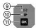
text_image
Diagram showing labeled parts of industrial equipment including a device, clamp, and robotic arm with numbered annotations.3.6 AFI (Active Fusion Indicator)
natural_image
Icon of a person reading a book inside a circle with a right-pointing arrow (no text or symbols)
text_image
QR code image containing encoded data, no visible human-readable text
text_image
HILTIHilti Corporation
LI-9494 Schaan
Tel.:+423 234 21 11
Fax:+423 234 29 65
www.hilti.group