122XL - Slicer RIDGID - Free user manual and instructions
Find the device manual for free 122XL RIDGID in PDF.
User questions about 122XL RIDGID
0 question about this device. Answer the ones you know or ask your own.
Ask a new question about this device
Download the instructions for your Slicer in PDF format for free! Find your manual 122XL - RIDGID and take your electronic device back in hand. On this page are published all the documents necessary for the use of your device. 122XL by RIDGID.
USER MANUAL 122XL RIDGID
Copper Cutting and Prep Machines
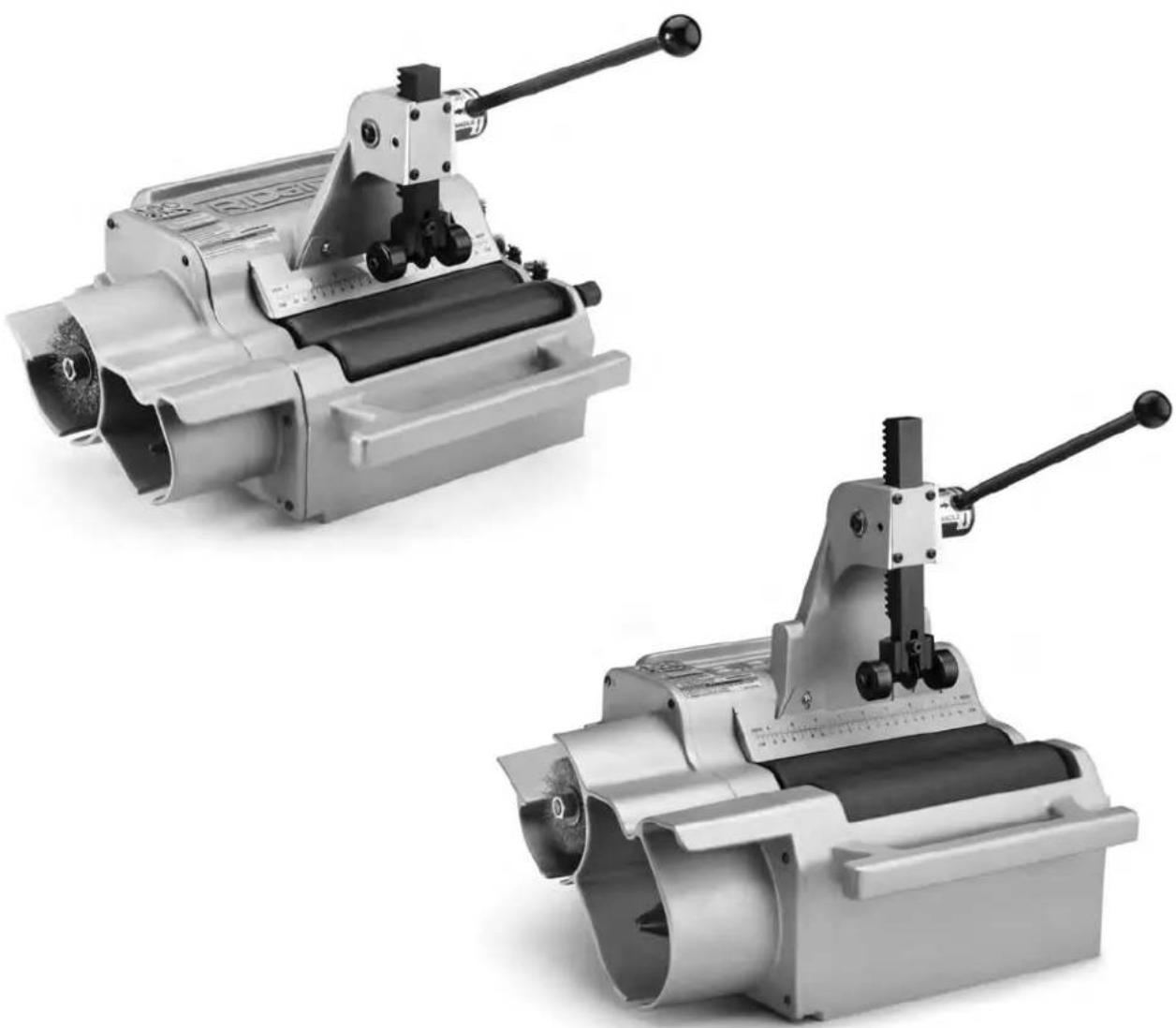
Table of Contents
Recording Form for Machine Serial Number 1
Safety Symbols 2
General Power Tool SafetyWarnings
Work Area Safety 2
Electrical Safety 2
Personal Safety 3
Power Tool Use and Care 3
Service 3
Specific Safety Information
Copper Cutting and Prep Machines Safety 4
Description, Specifications and Standard Equipment
Description 4
Standard Equipment 4
Specifications 5
Icons 6
Tool Assembly
FittingBrushesandHolder 6
O.D. Deburring Disk 6
Pre-Operation Inspection 6
Machine and Work Area Set-Up 7
Using Foot Switch (120V Only) 8
Operating Instructions
Cutting Tubes. 9
Cleaning/Deburring O.D. of Tube 10
Reaming I.D. of Tube 10
Cleaning Inside of Fittings 10
Maintenance Instructions
Cleaning. 11
Lubrication 11
Adjusting Rack Tension 11
Cutter Wheel Replacement 11
O.D. Brush Replacement 11
Reamer Blade Replacement 11
Motor Thermal Overload 12
Accessories 12
Storage 12
Service and Repair 12
Disposal 13
Troubleshooting 13
EC Declaration of Conformity . Inside Back Cover
Lifetime Warranty . Back Cover
*Original Instructions - English
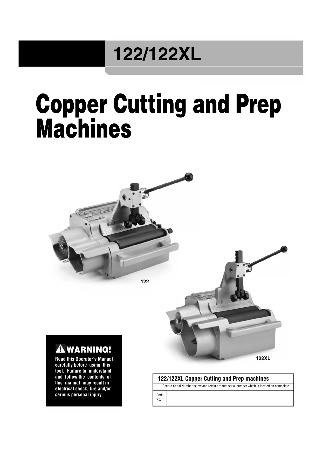
Copper Cutting and Prep Machines
122
122XL

WARNING!
Read this Operator's Manual carefully before using this tool. Failure to understand and follow the contents of this manual may result in electrical shock, fire and/or serious personal injury.
122/122XL Copper Cutting and Prep machines
Record Serial Number below and retain product serial number which is located on nameplate.
Serial No.
Safety Symbols
In this operator's manual and on the product, safety symbols and signal words are used to communicate important safety information. This section is provided to improve understanding of these signal words and symbols.

This is the safety alert symbol. It is used to alert you to potential personal injury hazards. Obey all safety messages that follow this symbol to avoid possible injury or death.

DANGER
DANGER indicates a hazardous situation which, if not avoided, will result in death or serious injury.

WARNING
WARNING indicates a hazardous situation which, if not avoided, could result in death or serious injury.

CAUTIO
CAUTION indicates a hazardous situation which, if not avoided, could result in minor or moderate injury.
NOTICE
NOTICE indicates information that relates to the protection of property.

This symbol means read the operator's manual carefully before using the equipment. The operator's manual contains important information on the safe and proper operation of the equipment.

This symbol means always wear safety glasses with side shields or goggles when handling or using this equipment to reduce the risk of eye injury.

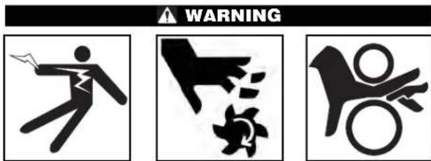
This symbol indicates the risk of hands, fingers or other body parts being caught or wrapped in rollers or other moving parts

This symbol indicates the risk of hands, fingers or other body parts being cut by the rotating reamer or wire brush or other moving parts
This symbol indicates the risk of machine tipping, causing striking or crushing injuries.
This symbol indicates the risk of electrical shock.

This symbol means do not wear gloves while operating this machine to reduce the risk of entanglement.
General Power Tool Safety Warnings*
WARNING
Read all safety warnings, instructions, illustrations and specifications provided with this power tool. Failure to follow all instructions listed below may result in electric shock, fire and/or serious injury.
SAVE ALL WARNING AND INSTRUCTIONS FOR FUTURE REFERENCE!
The term "power tool" in the warnings refers to your mains-operated (corded) power tool or battery-operated (cordless) power tool.
Work Area Safety
- Keep your work area clean and well lit. Cluttered or dark areas invite accidents.
-
Do not operate power tools in explosive atmospheres, such as in the presence of flam mable liquids, gases, or dust. Power tools create sparks which may ignite the dust or fumes.
-
Keep children and bystanders away while operating a power tool. Distractions can cause you to lose control.
Electrical Safety
- Power tool plugs must match the outlet. Never modify the plug in any way. Do not use any adapter plugs with earthed (grounded) power tools. Un modified plugs and matching outlets will reduce risk of electric shock.
- Avoid body contact with earthed or grounded surfaces such as pipes, radiators, ranges and refrigerators. There is an increased risk of electrical shock if your body is earthed or grounded.
- Do not expose power tools to rain or wet conditions. Water entering a power tool will increase the risk of electrical shock.
- Do not abuse the cord. Never use the cord for carrying, pulling or unplugging the power tool. Keep cord away from heat, oil, sharp edges or
moving parts. Damaged or entangled cords increase the risk of electric shock.
- When operating a power tool outdoors, use an extension cord suitable for outdoor use. Use of a cord suitable for outdoor use reduces the risk of electric shock.
- If operating a power tool in a damp location is unavoidable, use a ground fault circuit interrupter (GFCI) protected supply. Use of a GFCI reduces the risk of electric shock.
Personal Safety
- Stay alert, watch what you are doing and use common sense when operating a power tool. Do not use a power tool while you are tired or under the influence of drugs, alcohol, or medication. A moment of inattention while operating power tools may result in serious personal injury.
- Use personal protective equipment. Always wear eye protection. Protective equipment such as dust mask, non-skid safety shoes, hard hat, or hearing protection used for appropriate conditions will reduce personal injuries.
- Prevent unintentional starting. Ensure the switch is in the OFF-position before connecting to power source and/or battery pack, picking up or carrying the tool. Carrying power tools with your finger on the switch or energizing power tools that have the switch ON invites accidents.
- Remove any adjusting key or wrench before turning the power tool ON. A wrench or a key left attached to a rotating part of the power tool may result in personal injury.
- Do not overreach. Keep proper footing and balance at all times. This enables better control of the power tool in unexpected situations.
- Dress properly. Do not wear loose clothing or jewel ry. Keep your hair, clothing, and gloves away from moving parts. Loose clothes, jewelry, or long hair can be caught in moving parts.
- If devices are provided for the connection of dust extraction and collection facilities, ensure these are connected and properly used. Use of dust collection can reduce dust-related hazards.
- Do not let familiarity gained from frequent use of tools allow you to become complacent and ignore tool safety principles. A careless action can cause severe injury within a fraction of a second.
Power Tool Use and Care
- Do not force power tool. Use the correct power tool for your application. The correct power tool will do the job better and safer at the rate for which it is designed.
- Do not use power tool if the switch does not turn it ON and OFF. Any power tool that cannot be controlled with the switch is dangerous and must be repaired.
- Disconnect the plug from the power source and/or remove the battery pack, if detachable, from the power tool before making any adjustments, changing accessories, or storing power tools. Such preventive safety measures reduce the risk of starting the power tool accidentally.
- Store idle power tools out of the reach of children and do not allow persons unfamiliar with the power tool or these instructions to operate the power tool. Power tools are dangerous in the hands of untrained users.
- Maintain power tools and accessories. Check for misalignment or binding of moving parts, breakage of parts and any other condition that may affect the power tool's operation. If damaged, have the power tool repaired before use. Many accidents are caused by poorly maintained power tools.
- Keep cutting tools sharp and clean. Properly maintained cutting tools with sharp cutting edges are less likely to bind and are easier to control.
- Use the power tool, accessories and tool bits etc. in accordance with these instructions, taking into account the working conditions and the work to be performed. Use of the power tool for operations different from those intended could result in a hazardous situation.
- Keep handles and grasping surfaces dry, clean and free from oil and grease. Slippery handles and grasping surfaces do not allow for safe handling and control of the tool in unexpected situations.
Service
- Have your power tool serviced by a qualified repair person using only identical replacement parts. This will ensure that the safety of the power tool is maintained.
Specific Safety Information
WARNING
This section contains important safety information that is specific to this tool.
Read these precautions carefully before using the 122 and 122XL Copper Cutting and Prep Machines to reduce the risk of electrical shock or serious personal injury.
SAVE THESE INSTRUCTIONS!
Keep this manual with machine for use by the operator.
Copper Cutting and Prep Machines Safety
- Do not wear gloves or loose clothing. Keep sleeves and jackets buttoned. Clothing can be caught in rotating rollers or tools and cause crushing injuries.
- Secure machine to stable bench or stand. Properly support the tubes. This reduces the risk of falling tube, tipping and serious injury.
- Keep fingers and hands away from the rotating rollers, reamer, wire brushes, deburring disk and tube. This reduces the risk of entanglement and cutting injuries.
- Do not cut visibly bent tubing or tubing with fittings attached. Reduces the risk of excessive vibration and loss of control of the machine and/or tubing.
- Only use the machines to cut, clean and deburr copper or stainless steel tubing as directed in this manual. Do not use for other purposes or modify. Other uses or modifying this machine for other applications may increase the risk of serious injury.
- Read and understand the instructions and warnings for all equipment and material being used before operating the machines. Failure to follow all instructions and warnings may result in property damage or serious personal injury.
If you have any question concerning this RIDeProduct:
- Contact your local RIDGID distributor.
- Visit RIDGID.com to find your local RIDGID contact point.
- Contact Ridge Tool Technical Service Department at rtctechservices@emerson.com, or in the U.S. and Canada call (800) 519-3456.
Description, Specifications and Standard Equipment
Description
The RIDGID Model 122 and 122XL Copper Cutting and Prep Machines are designed to cut, clean and debrurr copper tubing and fittings (Types K, L and M). These can also be used to cut and debrurr stainless steel tubing with a maximum wall thickness of .065" (1.65 mm) with a separate cutter wheel.
Cutting is performed by turning the tubing with motor-driven rollers while a cutter wheel is manually actuated by a rack and pinion. An adjustable cutting handle accommodates different diameter tubes and a scale is included for tube measurement. Reamer removes burrs from the inside of the tubing while the brush cleans the external surface in preparation for joining. The machine can also clean the inside of fittings using individually sized brushes that are attached to the quick-change adapter. Deburring disk cleans burrs from the outside surface of the tubing.
The RIDGID Model 122 and 122XL Copper Cutting and Prep Machines are not designed for use with pipe.
Standard Equipment
The 122 and 122XL Copper Cutting and Prep Machines come with the following items:
O.D.Cleaning Brush
Cone Reamer
O. D. Deburring Disk (122XL Only)
Fitting Brush Storage Kit (122 Only)
Operator's Manual Pack
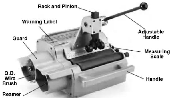
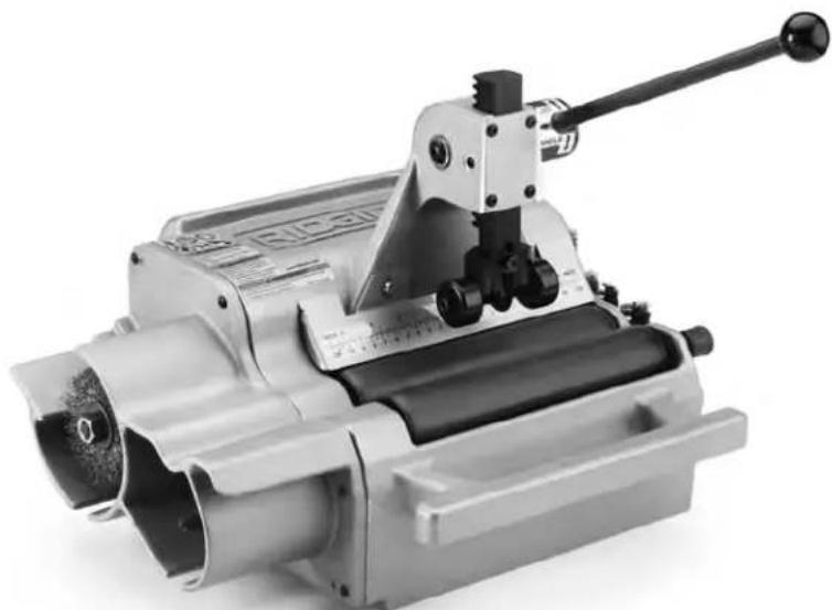
Figure 1A - 122 Copper Cutting and Prep Machine
Specifications
| Parameter 122 122XL | ||
| Capacity | 1/2" to 2" (12 mm to 54 mm) | 1/2" to 4" (12 mm to 108 mm) |
| Copper Tubes and Fittings ASTM B88 Type K, L & M ASTM B88 Type K, L & M Stainless Steel Tubes Max Wall Thickness 0.065" (1.65 mm) Max Wall Thickness 0.065" (1.65 mm) | ||
| Cutter Wheel Model 2191 HD (STD 115V) Model 122 SS Model 122 SS (STD, 100V, 230V) | ||
| Reamer Single Flute Cone, Single Flute Cone, RH 1/2" to 2" (12 mm to 54 mm) RH | 1/2" to 2" (12 mm to 54 mm) RH | 1/2" to 2" (12 mm to 54 mm) |
| Roller Speed 450 rpm 300 rpm | ||
| Motor Type | Induction Motor | Induction Motor |
| Motor Rating 100V | 100/200V, 50 Hz, 5.4/2.7 Amp | |
| Motor Rating 115V | 115V, 60 Hz, 1/3 HP, 3.2 Amp | 115V, 60 Hz, 1/3 HP, 3.2 Amp |
| Motor Rating 220V-240V | 220-240VAC, 50/60Hz, 2.2 Amp | 220-240VAC, 50/60Hz, 2.2 Amp |
| Switch | Toggle On/Off | Toggle On/Off |
| Weight | 50 lb (22,7 kg) | 72 lb (32,7 kg) |
| Dimensions (HxLxW) | 14.6" x 16.8" x 15.1" | 16.5" x 17.1" x 15.0" |
| (370 x 427 x 383 mm) | (419 x 434 x 381 mm) | |
| Sound Pressure (LpA)* | 75 dB(A), K=3 | 75 dB(A), K=3 |
- Sound measurements are measured in accordance with a standardized test per Standard EN 62481-1.
Sound emissions may vary due to your location and specific use of these tools. - Daily exposure levels for sound need to be evaluated for each application and appropriate safety measures taken when needed. Evaluation of exposure levels should consider the time a tool is switched off and not in use. This may significantly reduce the exposure level over the total working period.
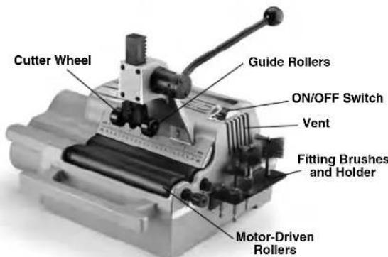
Figure 1B - 122 Copper Cutting and Prep Machine
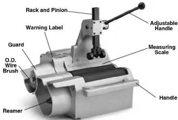
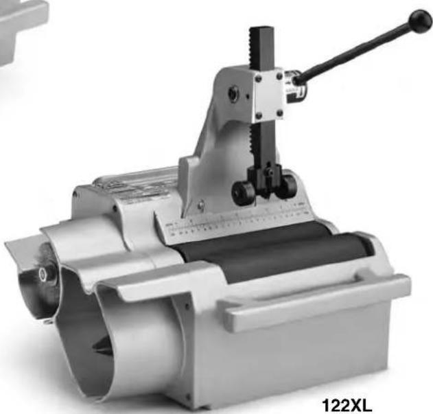
Figure 2A - 122XL Copper Cutting and Prep Machine

Figure 2B - 122XL Copper Cutting and Prep Machine
The machine serial number is located on the rear side of the machine. The last 4 digits indicate the month and year of the manufacture. (08 = month, 15 = year).
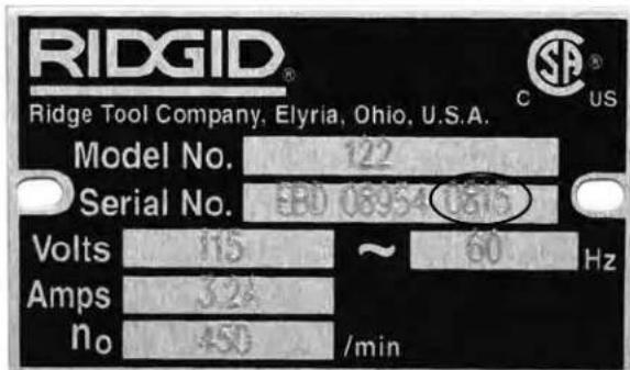
Figure 3 - Machine Serial Number
Icons

NOTICE Selection of appropriate materials and installation, joining and forming methods is the responsibility of the system designer and/or installer. Selection of improper materials and methods could cause system failure.
Stainless steel and other corrosion resistant materials can be contaminated during installation, joining and forming. This contamination could cause corrosion and premature failure. Careful evaluation of materials and methods for the specific service conditions, including chemical and temperature, should be completed before any installation is attempted.
Tool Assembly
WARNING
To reduce the risk of serious injury during use, follow these procedures for proper assembly.
ON/OFF switch should be OFF and machine un-plugged before assembly.
Fitting Brushes and Holder (optional accessory for the 122XL)
- Mount the fitting brush holder to the side of machine using provided screws
- Attach the quick-change collet (Figure 4) to the front roller shaft extending from machine housing using the setscrew. Securely tighten with 14 " hex key.
- Pull the collar of the collet to unlock and insert the brush shank, then release the collar to lock. Make sure the brush is secure. The brush can be replaced in similar manner.
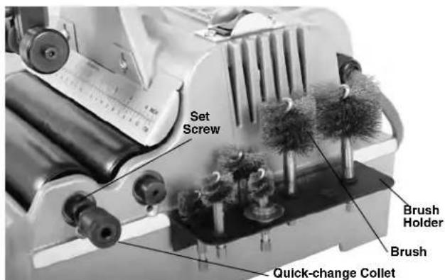
Figure 4 - Collet Installed
O. D. Deburring Disk (optional accessory for the 122)
- Hold the O.D. brush shaft stationary by gripping the flats located near the surface of the housing with a wrench (Figure 5).
- Remove the 12 nut and washer, and then remove the brush and spacer.
- With the disk model number (F-4697) recess facing the machine housing, slide the deburring disk onto the shaft and replace the brush. Spacer should not be used when the deburring disk is installed.
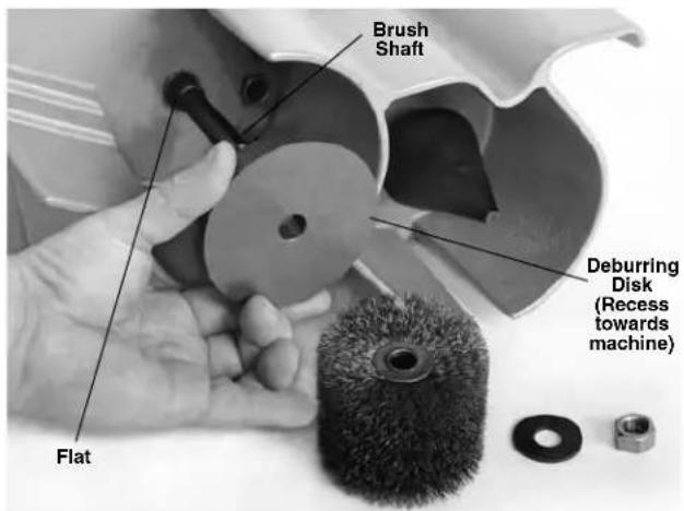
Figure 5 - Installing Deburring Disk
- Reinstall washer and 12 nut and securely tighten.
Pre-Operation Inspection
Before each use, inspect your Copper Cutting and Prep Machine and correct any problems to reduce the risk of serious injury from electric shock, entanglement, crushing and other causes and prevent machine damage.
- Make sure that the copper cutting and prep machine is unplugged and the ON/OFF switch is in OFF (O) position.
- Clean any oil, grease or dirt from the tool including handles and controls. This aids inspection and helps prevent the tool or control from slipping from your grip.
Clean dirt and debris from the rollers. Rollers must be kept clean to insure proper machine performance.
-
Inspect the copper cutting and prep machine for the following items:
-
Damage or modification to the cord and plug.
- Proper assembly, maintenance and completeness.
- Damaged, misaligned or binding parts.
- Free movement of adjustable handle, rack and pinion, cutter wheel and guide rollers
- Presence and readability of the warning label (see Figure 6).
- Any other condition which may prevent safe and normal operation.
If any problems are found, do not use the copper cutting and prep machine until the problems have been repaired.
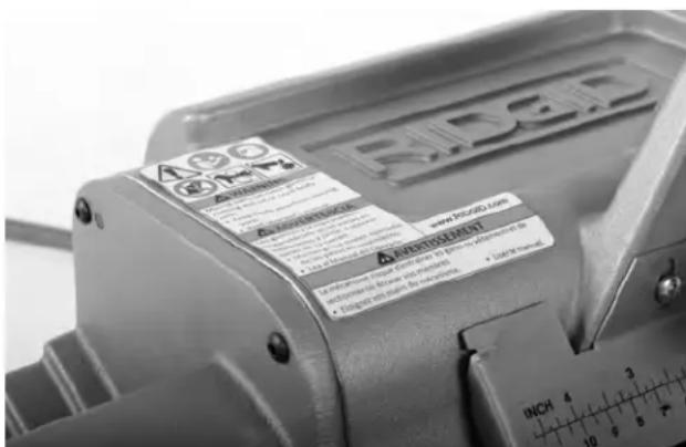
Figure 6 - Warning Label
- Inspect the cutter wheel, reamer, brush(es) and guide rollers for wear and damage. If necessary, replace prior to using the machine. Dull, damaged or de formed tools can lead to uneven cuts or cleaning, excessive bur formation, and slow the cutting or cleaning process.
- Inspect and maintain any other equipment being used per its instructions.
- Make sure that the ON/OFF switch is set to the OFF (O) position. With dry hands, plug cord into properly grounded outlet.
-
Move the ON/OFF switch into the ON (I) position and note the direction of rotation of the rollers. If the switch does not control the machine operation, do not use the machine until the switch has been repaired. The rollers should rotate counterclockwise when viewed from the reamer side of the machine. If the rotation is not correct, do not use the machine until it has been repaired.
-
After the inspection is complete, move the ON/OFF switch into the OFF (O) position and, with dry hands, unplug the machine.
Machine and Work Area Set-Up

WARNING


Set up the Copper Cutting and Prep Machine and work area according to these procedures to reduce the risk of injury from electrical shock, entanglement, crushing and other causes and prevent tool damage.
Secure machine to stable bench or stand. Properly support tube. This will reduce the risk of falling tube, tipping and serious injury.
Keep fingers and hands away from the rotating ream er, rollers, wire brush, deburring disk and tube. Reduces the risk of entanglement and cutting injuries.
-
Check work area for:
-
Adequate lighting.
- Flammable liquids, vapors or dust that may ignite. If present, do not work in area until sources have been identified and corrected. The copper cutting and prep machine is not explosion proof and can cause sparks.
- Clear, level, stable, dry place for operator. Do not use the machine while standing in water.
- Properly grounded electrical outlet of the correct voltage. A three-prong or GFCI outlet may not be properly grounded. If in doubt, have outlet inspected by a licensed electrician.
-
Clear path to electrical outlet that does not contain any potential sources of damage for the power cord.
-
Inspect the work to be done. Determine the material, type and size of the tube. Determine the correct equipment for the job. See "Specification" section for tool information.
- Confirm that the equipment to be used has been properly inspected.
- Place the machine on a flat, level, stable surface or a 1206 stand. If using a 1206 Stand, set up per its instructions. Bolt the machine down using the mounting holes located at the rear of the unit. Confirm that unit is stable and secure.
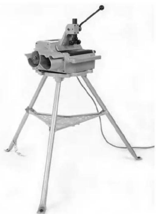
Figure 7-122XL on 1206 stand
- If tube will extend more than 6'' beyond the machine, use one or more stands to support the tube.
- Restrict access or set-up guards or barricades to create a minimum of 3 feet (1 m) of clearance around the machine and tube. This reduces the risk of entanglement or tipping from non-operators from contacting the machine or tube.
- Confirm that the ON/OFF switch is in OFF (O) position.
- Run the cord along the clear path. With dry hands plug the copper cutting and prep machine into a properly grounded outlet. Keep all connections dry. If the power cord is not long enough, use an extension cord that:
Is in good condition.
- Has a three-prong plug similar to that supplied on the machine.
Is rated for outdoor use and contains a W or W-A in the cord designation (i.e. SOW), or complies with H05VV-F, H05RN-F types or IEC type design (60227 IEC 53, 60245 IEC 57).
- Has sufficient wire size. For extension cords up to 50' (15.2 m) long use 16 AWG (1.5 mm²) or heavier. For extension cords 50' - 100' (15.2 m - 30.5 m) long use 14 AWG (2.5 mm²) or heavier.
Using Foot Switch (120V only)
For ease of operation, the 122 and 122XL can be used with Model 301A Foot Switch-120.
- With dry hands plug the 301A Foot Switch into a properly grounded outlet or extension cord.
- Confirm that the 122 or 122XL machine ON/OFF switch is in OFF (O) position. Plug the 122 or 122XL machine plug into the foot switch receptor.
- Turn the ON/OFF switch to ON (I) position.
- With hands clear of all rotating parts, press the foot switch and confirm that the foot switch controls the machine operation. Release the foot switch and let the machine come to a complete stop. Move the ON/OFF switch to the OFF (O) position.
Operating Instructions

WARNING
Always wear appropriate eye protection to protect your eyes against dirt and other foreign objects.
Do not wear gloves or loose clothing. Keep sleeves and jackets buttoned. Clothing can be caught in rotating rollers or tools and cause crushing injuries.
Keep fingers and hands away from rotating rollers, reamer, wire brushes and tube. This reduces the risk of entanglement and cutting injuries
Properly support long lengths of tubing. This reduces the risk of tipping or falling tube.
Do not cut visibly bent tubing or tubing with fittings attached. Reduces the risk of excessive vibration and loss of control of the tubing.
Follow operating instructions to reduce the risk of injury from electrical shock, entanglement, crushing and other causes and prevent machine damage.
- Confirm that the copper cutting and prep machine and work area are properly set up and the work area is free of bystanders and other distractions.
-
Assume a proper operating position to help maintain control the machine and process:
-
Be sure you have convenient access to the ON/OFF switch or can control the ON/OFF action of the foot switch if used.
-
Be sure that you have good balance, do not have to overreach, and cannot fall on the machine or other hazards.
-
Keep hands and fingers away from reamer, wire brushes and ends of the tubing.
This operating position will help to maintain control of tubing and the machine.
Cutting Tubes
- Check that the tubing is not visibly bent and no fittings are attached. Cutting bent tubes or tubes with fittings can result in excessive vibration and loss of control. Use a hand cutter if needed. Mark the tubing at the desired length. For convenience, a measuring scale is provided on the machine.
- Position the cutter handle to provide clearance for the tubing. To adjust the cutter wheel position, move handle to the right and relocate position pin by moving handle up or down according to the arrow marks shown on the handle label (see Figure 8).
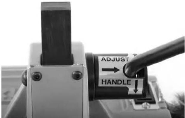
Figure 8 - Adjusting Handle Position
- Place the tubing on the rollers so that the cutting mark is located under the cutter wheel, on the zero mark of the scale. If the tubing extends beyond the machine, position supports under the tube. Supports should be adjusted so the tube sits squarely on the rollers. This will help insure proper tracking of the cut.
- Lower the handle until the cutter wheel support rollers contact the tubing (Figure 9). Align the cutter wheel with the mark on the tubing.
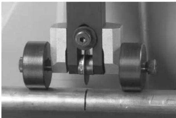
Figure 9 - Cutter Wheel Support Rollers Contacting Tubing
- Turn the ON/OFF switch to ON (I) position. The rollers and the tube will start to rotate. Keep hands way from rotating parts.
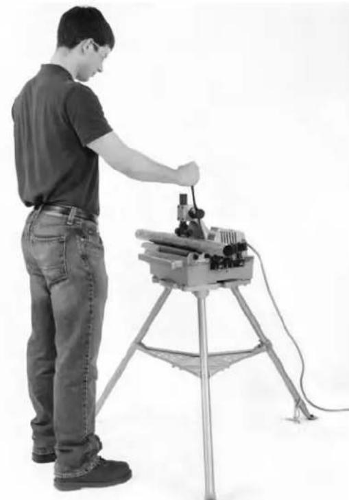
Figure 10 - Cutting Tubing
- Apply downward force to the handle slowly and continuously until the tubing is cut. Aggressive cutting can damage the cutter wheel and cause excessive burrs.
- Reduce force on the handle maintaining the support rollers in contact with the tubing. The rollers help hold the tubing in place.
-
Turn the ON/OFF switch to OFF (O) position.
-
When tubing stops rotating, remove from the machine. Raise the cutter handle.
Cleaning/Deburring O.D. of Tube
- Turn ON/OFF switch to ON (I) position. Keep hands away from the tube ends and rotating parts.
- Place the end of tube on the rest plate. Properly support the tube to help maintain control.
- For cleaning: Gently press the tube against the brush and rotate slowly until the surface is bright (Figure 11).
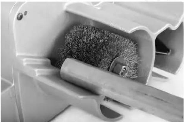
Figure 11 - Cleaning Tube O.D.
- For deburring: Gently press the tube end against the deburring disk to remove external burrs. Rotate the tube against deburring disk (Figure 12). This also bev els the end of the tube for easier insertion into fitting.
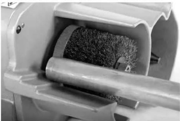
Figure 12 - Deburring O.D. Of Tube
- Turn the ON/OFF switch to OFF (O) position.
Reaming I.D. of Tube
- Turn ON/OFF switch to ON (I) position. Keep hands away from tube ends and rotating parts.
-
Securely grasp the tube. Properly support the tube to help maintain control.
-
Place the tubing over the reamer cone and gently apply pressure (Figure 13). Do not force the tube into the reamer. This will remove burrs from inside of the tubing. The maximum reaming capacity is 2^ (54 mm) tubing. Do not try to deburr larger tubes.
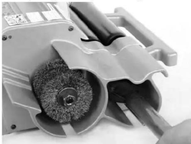
Figure 13 - Reaming I.D. of Tube
- Turn the ON/OFF switch to OFF (O) position.
Cleaning Inside of Fittings
- Check that the installed brush is the correct size for the fitting diameter. New brushes (up to 3^ size) are similar in size to the tube O.D. If needed, install correct size fitting brush on the quick-change collet as described in "Fitting Brushes and Holder" section of Tool Assembly.
- Turn ON/OFF switch to ON (I) position.
- Keep fingers away from brush. Push fitting over the rotating brush (Figure 14). Hold the fitting securely to prevent rotation and press O.D. of the fitting against the O.D. of the brush. Continue until fitting I.D. is clean, then pull fitting off of brush.
- Turn the ON/OFF switch to OFF (O) position.
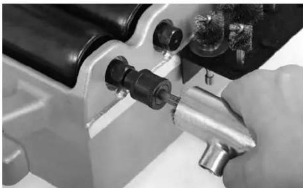
Figure 14 - Cleaning Inside of Fittings
Maintenance Instructions
WARNING
Make sure that the ON/OFF switch is in the OFF position and the machine is unplugged before performing any maintenance or making any adjustments.
Maintain tool according to these procedures to reduce the risk of injury from electrical shock, entanglement and other causes.
Cleaning
Gently clean the machine after each use with a clean dry cloth. Keep the rollers clean and free from dirt and debris.
Keep the reamer, brush, cutter wheel and deburring disk clean and free from chips for maximum efficiency.
Lubrication
Keep a light coat of lubricating oil on the rack and pinion, the cutter wheel shaft, and the guide roller shafts. Wipe up any excess oil.
Adjusting Rack Tension
Use a 5 / 32 " hex key to tighten or loosen rack tension set screw (Figure 15) as desired. Typically it is set just tight enough to prevent rack movement under its own weight.
Cutter Wheel Replacement
Replace the cutter wheel when the cutting edge becomes chipped or flat.
- Loosen the shoulder bolt and remove the roller and slide assembly (Figure 15). Do not remove the shoulder bolt, this keeps the tension spring in place.
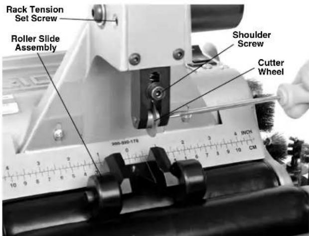
Figure 15 - Remove Cutter Wheel Screw
- Remove cutter wheel screw and replace the cutter wheel (Figure 15). See Accessories section for available cutter wheels.
- Reinstall the roller and slide assembly and securely tighten the shoulder bolt.
O.D. Brush Replacement
The O.D. Brush should be replaced when its bristles become uneven or too short to effectively clean the tubing. See Figure 5.
- Hold the O.D. brush shaft stationary by gripping the flat located near the surface of the housing with a 9/16 wrench.
- Remove the 12 nut and washer from the shaft and replace the brush.
- Reinstall washer and nut and securely tighten.
Reamer Blade Replacement
Replace reamer blade if it is damaged or dull.
- Remove reamer from its shaft by loosening set screw with a 5/32'' hex key.
- Unscrew two cap screws that hold the blade to the reamer cone. Replace the blade
- Reinstall reamer onto the shaft and secure with set screw.
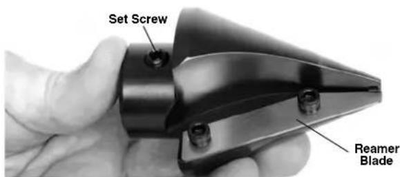
Figure 16 - Reamer
Motor Thermal Overload
The motor is equipped with a thermal overload that turns off the motor if it gets too hot.
To reset the thermal overload, unplug machine and turn ON/OFF switch to the OFF (O) position and allow the motor to cool for 15 minutes. Use a thin, non-conductive probe to reach through the vent (Figures 1 and 2) to press the reset button (Figure 17).
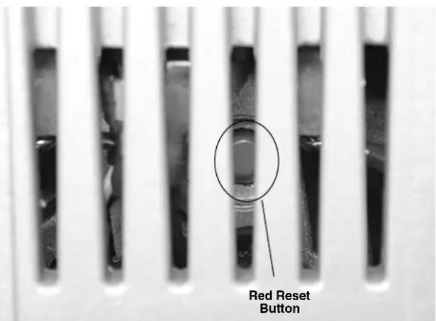
Figure 17 - Motor Reset Button
If motor does not start or the thermal overload continually trips during normal operation, the machine should be taken to RIDGID Authorized Service Center.
Accessories
WARNING
To reduce the risk of serious injury, only use accessories specifically designed and recommended for use with the 122 and 122XL Copper Cutting and Prep Machines such as those listed below. Other Accessories suitable for use with other tools may be hazardous when used with the 122 and 122XL Copper Cutting and Prep Machines.
| Catalog No. | Model Description |
| 33175 2 | 191 Cutter Wheel for Copper |
| 34360 — | Wheel Screw for 2191 Cutter Wheel |
| 33551 1 | 22SS Cutter Wheel for Copper and Stainless Steel |
| 10343 — | Wheel Pin for 33551 Cutter Wheel |
| 46105 — | O.D. Deburring Disk |
| 94682 — | O.D. Cleaning Brush |
| 94687 — | 2" Reamer Cone Assembly |
| 36662 301A | Model 301A Foot Switch – 120V Only |
| 42360 1 | 1206 1206 Stand |
| 94692 — | Reamer Blade |
Fitting Brush and Holder
| Catalog No. | Description |
| 93747 | Quick-Change Collet |
| 93717 | \( ^1/2^* \)Fitting Brush (3 Per Pack) |
| 93722 | \( ^3/4^* \)Fitting Brush (3 Per Pack) |
| 93727 | 1" Fitting Brush (3 Per Pack) |
| 93732 | \( 1'/4" \)Fitting Brush (3 Per Pack) |
| 93737 | \( 1'/2" \)Fitting Brush (3 Per Pack) |
| 93742 | 2" Fitting Brush (3 Per Pack) |
| 12638 | \( 2'/2" \)Fitting Brush (3 Per Pack) - 122XL Only |
| 12643 | \( 3" - 4" \)Fitting Brush (3 Per Pack) - 122XL Only |
| 93707 | Fitting Brush Storage Kit Includes Mountable Storage Rack, Quick-Change Collet, Spare Cutter Wheel and Brushes\( (/z^*, 3/4^*, 1^*, 1/4^*, 1/2, 2^*) \) |
| 93712 | Fitting Brush Holder |
Further information on accessories specific to this tool can be found in the RIDGID Catalog and online at RIDGID.com or RIDGID.eu
Machine Storage
WARNING The 122 and 122XL Copper Cutting and Prep Machines must be kept indoors or well covered in rainy weather. Store the machine in a locked area that is out of reach of children and people unfamiliar with the machines. These machines can cause serious injury in the hands of untrained users.
Service and Repair
WARNING
Improper service or repair can make machine unsafe to operate.
The "Maintenance Instructions" will take care of most of the service needs of this machine. Any problems not addressed by this section should only be handled by an authorized RIDGID service technician.
Tool should be taken to a RIDGID Independent Service Center or returned to the factory.
For information on your nearest RIDGID Independent Service Center or any service or repair questions:
- Contact your local RIDGID distributor.
- Visit RIDGID.com to find your local RIDGID contact point.
- Contact Ridge Tool Technical Service Department at rtctechservices@emerson.com or in the U.S. and Canada call (800) 519-3456
Disposal
Parts of the 122 and 122XL Copper Cutting and Prep Machines contain valuable materials and can be recycled. There are companies that specialize in recycling that may be found locally. Dispos of the components in compliance with all applicable regulations. Contact your local waste management authority for more information.
For EC Countries: Do not dispose of electrical equipment with household waste!
According to the European Guideline 2002/ -96/ EC for Waste Electrical and Electronic Equipment and its implementation into national legislation, electrical equipment that is no
longer usable must be collected separately and disposed of in an environmentally correct manner.
Troubleshooting
| SYMPTOM POS | SIBLE REASONS SOLUTION | |
| Excessive vibration during operation. | Cutting bent tubes on machine. | Do not cut visibly bent tubes on machine. Use hand cutter, or straighten tubes before cutting. |
| Long tubes not properly supported. | Support longer tubes with pipe stands. | |
| Machine not properly mounted. | Properly mount the machine on flat surface, bolt with the mounting bolts. | |
| Machine not cutting tubes properly. | Worn blades or cutter wheel. | Replace worn blades or cutter wheel. |
| Use on incorrect tube size or material. | Use on correct type of tubes (see Specifications). | |
| Machine stalls while cutting. | Applying excessive force on the handle while cutting | Gently apply force on the handle. |
| Excessive tube burrs or end deformation. | Worn or damaged cutter wheel. | Replace cutter wheel. |
| Applying excessive force on the handle while cutting. | Gently apply force on the handle. |
RIDGID® 122/122XL Copper Cutting and Prep Machines
RIDGE TOOL COMPANY
400 Clark Street
Elyria, Ohio 44035-6001
U.S.A.
Ridge Tool Europe NV (RIDGID)
Schurhovenveld 4820
3800 Sint-Truiden
Belgium
EC DECLARATION OF CONFORMITY
We declare that the machines listed above, when used in accordance with the operator's manual, meet the relevant requirements of the Directives and Standards listed below.
DECLARATION DE CONFORMITE CE
DEKLARACJA ZGODNOSCI WE
RIDGID® tools are warranted to be free of defects in workmanship and material.
How long coverage lasts
This warranty lasts for the lifetime of the RIDGID tool. Warranty coverage ends when the product becomes unusable for reasons other than defects in workmanship or material.
How you can get service
To obtain the benefit of this warranty, deliver via prepaid transportation the complete product to RIDGE TOOL COMPANY, Elvria, Ohio, or any authorized RIDGIDNDEPENDENT SERVICE CENTER. Pipe wrenches and other hand tools should be returned to the place of purchase.
What we will do to correct problems
Warranted products will be repaired or replaced, at RIDGE TOOL'S option, and returned at no charge; or, if after three attempts to repair or replace during the warranty period the product is still defective, you can elect to receive a full refund of your purchase price.
What is not covered
Failures due to misuse, abuse or normal wear and tear are not covered by this warranty. RIDGE TOOL shall not be responsible for any incidental or consequential damages.
How local law relates to the warranty
Some states do not allow the exclusion or limitation of incidental or consequential damages, so the above limitation or exclusion may not apply to you. This warranty gives you specific rights, and you may also have other rights, which vary, from state to state, province to province, or country to country.
No other express warranty applies
This FULL LIFETIME WARRANTY is the sole and exclusive warranty for RIDGID® products. No employee, agent, dealer, or other person is authorized to alter this warranty or make any other warranty on behalf of the RIDGE TOOL COMPANY.
Ce qui est couvert?
Parts are available online at Store.RIDGID.com
Ridge Tool Company
400 Clark Street
Elyria, Ohio 44035-6001
U.S.A.