
PTC400 - Slicer RIDGID - Free user manual and instructions
Find the device manual for free PTC400 RIDGID in PDF.

| Product type | Electric tube cutter (trencher) |
| Brand | RIDGID |
| Model | PC116 / PTC-400 |
| Cutting capacity (nominal diameter) | ½" to 4" (12 mm to 100 mm) |
| Cutting capacity (actual diameter) | ½" to 4.5" (12 mm to 116 mm) |
| Reaming capacity (optional) | ½" to 2" (12 mm to 50 mm) |
| Compatible materials | Steel, stainless steel, aluminum, copper, plastic |
| Power supply | 220-240 V, 50/60 Hz, 3 A, 705 W |
| Rotational speed | 190/363 rpm (low/high speed) |
| Control | Switch I (low) / O (off) / II (high) + pneumatic foot pedal |
| Operating temperature range | -20°C to 50°C |
| Sound pressure level | 82.3 dB(A) (K=3) |
| Sound power level | 93.3 dB(A) (K=3) |
| Main functions | Cutting metal and plastic tubes, optional reaming, two speeds, quick diameter adjustment |
| Maintenance | Monthly lubrication (light mineral oil), regular cleaning, brush replacement every 6 months, replace cutting wheel if worn |
| Safety | Motor thermal protection, automatic shut-off in case of overload, foot pedal control, wheel locking |
| Available spare parts | Cutting wheels (E-850 for metals, E-855 for plastic), motor brushes, 137S reamer, PC116TS tube holder, wheel bearing |
| Warranty | Full Lifetime Warranty covering defects in materials and workmanship |
| Included accessories | Metal cutting wheel (E-850), plastic cutting wheel (E-855) depending on version, reamer optional |
| Weight | Approximately 15 kg (estimation) |
| Dimensions (L x W x H) | Approximately 45 x 30 x 35 cm (estimation) |
Frequently Asked Questions - PTC400 RIDGID
User questions about PTC400 RIDGID
0 question about this device. Answer the ones you know or ask your own.
Ask a new question about this device
Download the instructions for your Slicer in PDF format for free! Find your manual PTC400 - RIDGID and take your electronic device back in hand. On this page are published all the documents necessary for the use of your device. PTC400 by RIDGID.
USER MANUAL PTC400 RIDGID
PC116/PTC-400 Power Tubing Cutter

natural_image
Ridgiz industrial machine with red handle and control panel, no visible text or symbols on the device itself.- Français- 15
- Castellano – 31
- Deutsche – 47
Table of Contents
Recording Form for Machine Serial Number 1
Safety Symbols 2
General Power Tool Safety Warnings
Work Area Safety 2
Electrical Safety 2
Personal Safety 3
Power Tool Use and Care ....3
Service ....3
Specific Safety Information ....3
RIDGID Contact Information 4
Description 4
Specifications 5
Standard Equipment 5
Assembly 5
Bench Mounting 5
Pre-Operation Inspection....6
Machine and Work Area Set-Up....6
PC116ST Stand/Adjustment 7
Operating Instructions 8
Adjusting Cutter For Different Tube Sizes 8
Selecting/Changing Operating Speed 8
Cutting Tube....9
Reaming Tube 10
Transportation 10
Storage....10
Maintenance Instructions
Cleaning....11
Lubrication 11
Changing Cutter Wheel 11
Motor Overcurrent Protection....11
Changing Motor Brushes 11
Troubleshooting 13
Service And Repair 13
Optional Equipment 13
Disposal....14
EC Declaration of Conformity....Inside Back Cover
Lifetime Warranty ....Back Cover
*Original Instructions - English
Tubing Cutter
PC116/PTC-400 Power Tubing Cutter

natural_image
Ridgid industrial machine with handle and control panel, no visible text or symbols on the device itself.
WARNING!
Read this Operator's Manual carefully before using this tool. Failure to understand and follow the contents of this manual may result in electrical shock, fire and/or serious personal injury.
| PC116/PTC-400 Power Tubing Cutter | |
| Record Serial Number below and retain product serial number which is located on name plate. | |
| Serial No. | |
Safety Symbols
In this operator's manual and on the product, safety symbols and signal words are used to communicate important safety information. This section is provided to improve understanding of these signal words and symbols.

This is the safety alert symbol. It is used to alert you to potential personal injury hazards. Obey all safety messages that follow this symbol to avoid possible injury or death.

DANGER
DANGER indicates a hazardous situation which, if not avoided, will result in death or serious injury.

WARNING
WARNING indicates a hazardous situation which, if not avoided, could result in death or serious injury.

CAUTION
CAUTION indicates a hazardous situation which, if not avoided, could result in minor or moderate injury.
NOTICE
NOTICE indicates information that relates to the protection of property.

This symbol means read the operator's manual carefully before using the equipment. The operator's manual contains important information on the safe and proper operation of the equipment.

This symbol means always wear safety glasses with side shields or goggles when handling or using this equipment to reduce the risk of eye injury.

This symbol indicates the risk of electrical shock.

This symbol indicates the risk of hands, fingers or other body parts being caught or wrapped in rollers or other moving parts.

This symbol indicates the risk of hands, fingers or other body parts being cut by the rotating or moving parts.

This symbol indicates the risk of machine tipping, causing striking or crushing injuries.

This symbol means do not wear gloves while operating this machine to reduce the risk of entanglement.
General Power Tool Safety Warnings\*
WARNING
Read all safety warnings, instructions, illustrations and specifications provided with this power tool. Failure to follow all instructions listed below may result in electric shock, fire, and/or serious injury.
SAVE ALL WARNINGS AND INSTRUCTIONS FOR FUTURE REFERENCE!
The term "power tool" in the warnings refers to your mains-operated (corded) power tool or battery-operated (cordless) power tool.
Work Area Safety
- Keep work area clean and well lit. Cluttered or dark areas invite accidents.
- Do not operate power tools in explosive atmospheres, such as in the presence of flammable liquids, gases, or dust. Power tools create sparks which may ignite the dust or fumes.
- Keep children and by-standers away while operating a power tool. Distractions can cause you to lose control.
Electrical Safety
- Power tool plugs must match the outlet. Never mod ify the plug in any way. Do not use any adapter plugs with earthed (grounded) power tools. Unmodified plugs and matching outlets will reduce risk of electric shock.
- Avoid body contact with earthed or grounded surfaces such as pipes, radiators, ranges and refrigerators. There is an increased risk of electrical shock if your body is earthed or grounded.
- Do not expose power tools to rain or wet conditions. Water entering a power tool will increase the risk of electrical shock.
- Do not abuse the cord. Never use the cord for carrying, pulling or unplugging the power tool. Keep cord away from heat, oil, sharp edges or moving parts. Damaged or entangled cords increase the risk of electric shock.
- When operating a power tool outdoors, use an extension cord suitable for outdoor use. Use of a cord suitable for outdoor use reduces the risk of electric shock.
- If operating a power tool in a damp location is unavoidable, use a ground fault circuit interrupter
(GFCI) protected supply. Use of a GFCI reduces the risk of electric shock.
Personal Safety
- Stay alert, watch what you are doing and use common sense when operating a power tool. Do not use a power tool while you are tired or under the influence of drugs, alcohol, or medication. A moment of inattention while operating power tools may result in serious personal injury.
- Use personal protective equipment. Always wear eye protection. Protective equipment such as dust mask, non-skid safety shoes, hard hat, or hearing protection used for appropriate conditions will reduce personal injuries.
- Prevent unintentional starting. Ensure the switch is in the OFF position before connecting to power source and/or battery pack, picking up or carrying the tool. Carrying power tools with your finger on the switch or energizing power tools that have the switch ON invites accidents.
- Remove any adjusting key or wrench before turning the power tool ON. A wrench or a key left attached to a rotating part of the power tool may result in personal injury.
- Do not overreach. Keep proper footing and balance at all times. This enables better control of the power tool in unexpected situations.
- Dress properly. Do not wear loose clothing or jewelry. Keep your hair, and clothing away from moving parts. Loose clothes, jewelry, or long hair can be caught in moving parts.
- If devices are provided for the connection of dust extraction and collection facilities, ensure these are connected and properly used. Use of dust collection can reduce dust-related hazards.
- Do not let familiarity gained from frequent use of tools allow you to become complacent and ignore tool safety principles. A careless action can cause severe injury within a fraction of a second.
Power Tool Use and Care
- Do not force power tool. Use the correct power tool for your application. The correct power tool will do the job better and safer at the rate for which it is designed.
-
Do not use power tool if the switch does not turn it ON and OFF. Any power tool that cannot be controlled with the switch is dangerous and must be repaired.
-
Disconnect the plug from the power source and/or the battery pack, if detachable, from the power tool before making any adjustments, changing accessories, or storing power tools. Such preventive safety measures reduce the risk of starting the power tool accidentally.
- Store idle power tools out of the reach of children and do not allow persons unfamiliar with the power tool or these instructions to operate the tool. Power tools are dangerous in the hands of untrained users.
- Maintain power tools. Check for misalignment or binding of moving parts, breakage of parts and any other condition that may affect the power tool's operation. If damaged, have the power tool repaired before use. Many accidents are caused by poorly maintained power tools.
- Keep cutting tools sharp and clean. Properly maintained cutting tools with sharp cutting edges are less likely to bind and are easier to control.
- Use the power tool, accessories and tool bits etc. in accordance with these instructions, taking into account the working conditions and the work to be performed. The use of the power tool for operations different from those intended could result in a hazardous situation.
- Keep handles and grasping surfaces dry, clean and free from oil and grease. Slippery handles and grasping surfaces do not allow for safe handling and control of the tool in unexpected situations.
Service
- Have your power tool serviced by a qualified repair person using only identical replacement parts.
This will ensure that the safety of the power tool is maintained.
Specific Safety Information
WARNING
This section contains important safety information that is specific to this tool.
Read these precautions carefully before using the PC116/PTC-400 Power Tubing Cutter to reduce the risk of electrical shock or other serious injury.
SAVE ALL WARNINGS AND INSTRUCTIONS FOR FUTURE REFERENCE!
Keep this manual with machine for use by the operator.
- Do not wear gloves or loose clothing when operating Power Tubing Cutter. Keep sleeves and jack-
ets buttoned. Do not reach across machine. Clothing can be caught by the machine resulting in entanglement.
- Keep hands away from rotating parts such as rollers, reamer, cutting wheel and tube. Allow parts to come to a complete stop before handling the tool or tube. This practice will reduce the chance of entanglement in rotating parts.
- Secure machine to stable bench or stand. Properly support the tubes. This will reduce the risk of striking and crushing injuries from tipping and falling tube and equipment.
- Do not cut visibly bent tubing or tubing with fittings attached. Reduces the risk of excessive vibration and loss of control of the machine and/or tubing.
• Always wear appropriate eye protection and appropriate personal protective equipment. Cutting tools can break or shatter. This will reduce the risk of injury.
- One person must control the work process and the foot switch. Only the operator should be in the work area when the machine is running. This helps reduce the risk of injury.
- Read and understand these instructions and the instructions and warnings for all equipment and materials being used before operating this tool to reduce the risk of serious personal injury.
RIDGID Contact Information
If you have any question concerning this RIDG Product:
- Contact your local RIDGID® distributor.
- Visit RIDGID.com to find your local RIDGID contact point.
- Contact Ridge Tool Technical Service Department at rttechservices@emerson.com, or in the U.S. and Cana da call (800) 519-3456.
Description
The RIDGID® PC116/PTC-400 Power Tubing Cutter is designed to cut ½" to 4" nominal size (12 to 100 mm) metallic and plastic tubing/conduit.
A two speed switch controls the roller speed and a pneumatic foot switch provides ON/OFF control of the motor. A scale is included for tube measurement. The Power Tubing Cutter is lightweight and compact for ease of transport.
An optional reamer is available to remove burrs from the inside of tubing up to 2" (50 mm).
The tubing cutter is not designed for use with pipe.
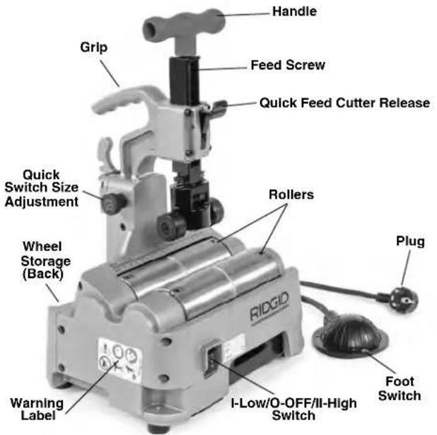

Figure 1 – RIDGID® PC116/PTC-400 Power Tubing Cutter

Figure 2 – Machine Serial Number
The machine serial number is located on the side of the cutter. The last 4 digits indicate the month and year of manufacture. (10 = month, 19 = year).
Specifications
Nominal Tube Size
Cutting Capacity.....1/2" to 4" (12 mm to 100 mm)
Actual Cutting
Capacity ....½" to 4.5" (12 mm to 116 mm)
| Tube/Conduit Maximum Wall CutterWheel | |||
| Material* | Thickness | E-850 | E-855 |
| Cat. #66938 | Cat. #66943 | ||
| Carbon Steel | 0.1" (2.5 mm) | X | |
| Stainless Steel | 0.1" (2.5 mm) | X | |
| Aluminum | 0.1" (2.5 mm) | X | |
| Copper | 0.1" (2.5 mm) | X | |
| Plastic | 0.23" (6 mm) | X | |
* General guideline only. Material composition, hardness and other factors affect ability to cut, wheel life, burr formation, etc
Nominal Reaming
Capacity ....½" to 2" (12 mm to 50 mm) (optional accessory)
Max. Tube Length ....20' (6m)
Motor
Type ....Universal
Voltage.....100-120V 220-240V
Current 5.8 A 3.0A
Frequency .....50/60 Hz 50/60 Hz
Power 705W 705W
Refer to on-product serial plate for information specific to unit.
Roller Rotational
Speed....190/363 RPM for 220-240V, 225/385 RPM for 100-120V
Controls....I-LOW/O-OFF/II-HIGH Switch and ON/OFF Foot Switch
Weight 32 lbs. (14.5 kg)
Overall Dimension
L x W x H.....11.6" × 9.4" × 15.9"
(295 mm × 239 mm × 403 mm)
Operating
Temperature.....-4°F to 122°F (-20°C to 50°C)
Sound Pressure ( L_A )* ...82.3 dB(A), K=3
Sound Power ( I_WA )*......93.3 dB(A), K=3
* Sound measurements are measured in accordance with a standardized test per Standard EN 62481-1.
- Sound emissions may vary due to your location and specific use of these tools.
- Daily exposure levels for sound need to be evaluated for each application and appropriate safety measures taken when needed. Evaluation of exposure levels should consider the time a tool is switched OFF and not in use. This may significantly reduce the exposure level over the total working period.
Standard Equipment
Refer to the RIDGID catalog for details on equipment supplied with specific machine catalog numbers.
NOTICE Selection of appropriate materials and installation, joining and forming methods is the responsibility of the system designer and/or installer. Selection of improper materials and methods could cause system failure.
Stainless steel and other corrosion resistant materials can be contaminated during installation, joining and forming. This contamination could cause corrosion and premature failure. Careful evaluation of materials and methods for the specific service conditions, including chemical and temperature, should be completed before any installation is attempted.
To reduce the risk of ferrous contamination of stainless steel, make sure that the rollers are clean and debris free. Thoroughly clean with a stainless steel brush. Change the cutter wheel and reamer before use with stainless steel material. Best practice is to dedicate a cutter for stainless steel.
Assembly
WARNING
To reduce the risk of serious injury during use, follow these procedures for proper assembly. Switch should be OFF and machine unplugged before assembly.
Bench Mounting
The machine can be mounted on a level, stable bench. To mount the unit on a bench, unscrew the rubber feet at the four corners of the machine base (See Figure 16) and use M8 bolts to retain machine to the bench. Tighten securely.
Pre-Operation Inspection
WARNING


Before each use, inspect your Power Tubing Cutter and correct any problems to reduce the risk of serious injury from electric shock, entanglement, crushing injuries and other causes and prevent machine damage.
- Make sure that the Power Tubing Cutter is unplugged.
- Clean the machine and equipment, including handles and controls. This aids inspection and helps prevent the machine or control from slipping from your grip. Clean and maintain the machine per the maintenance instructions.
-
Inspect the Power Tubing Cutter for:
-
Inspect the cord and plug for damage or modification.
- Proper assembly, maintenance and completeness.
- Any broken, worn, missing, misaligned or binding parts or other damage.
- Presence and operation of the foot switch. Confirm that foot switch is attached, in good condition, that it cycles smoothly and does not stick.
- Free movement of feedscrew, cutter wheel and support rollers.
- Presence and readability of the warning and other labels (See Figure 1).
- Inspect the cutting edges of the cutter wheel and reamer for wear, deformation, chips or other issues. Dull, damaged or loose cutters can damage the tool, produce poor quality cut and increase the risk of injury.
- If using the PC116TS stand(s), clean, inspect and lubricate as needed.
- Any condition which may prevent safe and normal operation.
If any problems are found, do not use the tool until the problems have been repaired.
- Inspect and maintain any other equipment being used per its instructions to make sure it is functioning properly.
Machine and Work Area Set-Up
WARNING


Set up the Power Tubing Cutter and work area according to these procedures to reduce the risk of serious injury from electric shock, entanglement, crushing injuries and other causes and prevent machine damage.
-
Check work area for:
-
Adequate lighting.
- Flammable liquids, vapors or dust that may ignite. If present, do not work in area until sources have been identified and corrected. The cutter is not explosion proof and can cause sparks.
- Clear, level, stable, dry location for all equipment and operator.
-
Properly grounded electrical outlet of the correct voltage. Check machine serial plate for required voltage. A three-prong or GFCI outlet may not be properly grounded. If in doubt, have outlet inspected by a licensed electrician.
-
Inspect the work to be done. Determine the material, type and size of the tube. Determine the correct equipment for the job. See Specifications section.
- Confirm all equipment to be used has been properly inspected and assembled.
- Place the machine on a flat, level, stable surface. See "Bench Mounting" in Assembly section. Confirm that unit is stable and secure.
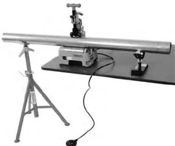
- If tube will extend more than 6" (15 cm) beyond the machine, use one or more appropriate stands to support the tube. Place the stands in line with rollers. Longer tube may need more than one stand. Only use stands designed for this purpose. Improper supports or supporting the tube by hand can cause tipping or entanglement injuries. Do not exceed the marked stand capacity. When the cutter and stand are sitting on the same plane, use the RIDGID PC116TS Tube Stand to support the tube.
If working on a bench or other raised work area, a variety of RIDGID Pipe Stands can be used to support the tube. If using the PC116/PTC-400 on the ground, use the RIDGID PC116TS Tube Stand to support the tube. See Figure 3.
natural_image
Experimental optical setup with a long cylindrical device mounted on a base, connected to a tripod and a small sensor (no visible text or symbols)Figure 3 – Stand placement
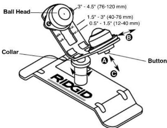
Figure 4 – PC116TS Stand Adjustment
PC116TS Stand/Adjustment
PC116TS Stand is an optional accessory designed for use with PC116/PTC-400 Cutter and not intended for other uses.
To adjust ball heads for tube size:
a. Depress buttonA
b. Move ball head to proper tube size position (see Figure 4) B
c. Release button – confirm securely located
To adjust stand height, turn collar to raise or lower stand head. Stand is designed to be placed on the same flat surface as the PC116/PTC-400 Cutter. See Figure 3. If needed, suitable spacers (such as a piece of wood) can be used to raise stand.
- Restrict access or set up guards or barricades to create a minimum of 3 feet (1 m) of clearance around
the machine and tube. This helps prevent non-operators from contacting the machine or tube and reduces the risk of tipping or entanglement.
- Position the foot switch as shown in Figure 8 to allow a proper operating position.
- With the switch in the O-OFF position, run the cord along a clear path. With dry hands, plug the power cord into the properly grounded outlet. Keep all connections dry and off the ground. If the power cord is not long enough, use an extension cord that:
- Is in good condition.
- Has a three-prong plug like on the power tubing cutter.
• Is rated for outdoor use.
- Has sufficient wire size. For extension cords up to 50' (15.2 m) long use 14 AWG (2.5 mm²) or heavier. For extension cords 50' -100' (15.2 m - 30.5 m) long use 12 AWG (2.5 mm²) or heavier.
-
Check the power tubing cutter for proper operation. With hands clear:
-
Move the speed switch to the I-LOW speed position. Press and release the foot switch. The rollers should rotate as indicated by the arrows in Figure 5. If the machine does not rotate in the correct direction, or the foot switch does not control the machine operation, do not use the machine until it has been repaired.
- Depress and hold the foot switch. Inspect the moving parts for misalignment, binding, odd noises or any other unusual conditions. Remove foot from the foot switch. If any unusual conditions are found, do not use the machine until it has been repaired.

Figure 5 – Roller Direction of Rotation
- Move the speed switch to the O-OFF position, and with dry hands unplug the machine.
Operating Instructions
WARNING

buttoned. Do not reach across machine. Clothing can be caught by the machine resulting in entanglement.
Keep hands away from rotating parts such as rollers, reamer, cutting wheel and tube. Allow parts to come to a complete stop before handling the tool or tube. This practice will reduce the chance of entanglement in rotating parts.
Properly support the tubes. This will reduce the risk of striking and crushing injuries from tipping and falling tube and equipment.
One person must control the work process and the foot switch. Only the operator should be in the work area when the machine is running. This helps reduce the risk of injury.
Follow operating instructions to reduce the risk of serious injury from electric shock, entanglement, crushing injuries and other causes and prevent machine damage.
Make sure that machine and work area is properly set up and that the work area is free of bystanders and other distractions. The operator should be the only person in the area while the machine is operated.
Adjusting Cutter For Different Tube Sizes Quick Switch Size Adjustment
The quick switch size adjustment is provided to quickly adjust between tube size ranges 2" (50mm) and smaller and 2" to 4" (50 mm to 100 mm).
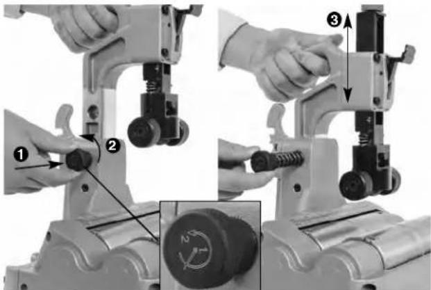
Figure 6 – Quick Switch Size Adjustment
-
With no tube in cutter, grasp grip and release the pin by slightly depressing the knob and turning slightly counter-clockwise ②The knob is spring loaded and will retract, control the movement of the knob. See Figure 6.
-
Using grip, move head to desired position③
-
Insert the quick switch knob to retain head in position.
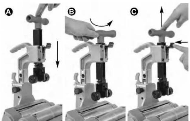
Quick Feed Cutter Adjustment
This quick feed cutter adjustment is used to advance and retract the cutter wheel during cutting operation.
-
To advance the cutter wheel, push the handle down (Figure 7A) until it engages the tube.
-
To retract cutter wheel, loosen the handle/feedscrew 1-2 turns (Figure 7B) and press the release (Figure 7C) to allow it to retract (it is spring loaded – control the movement of the handle).
natural_image
Three-step mechanical assembly diagram showing hand positioning and tool movement (no text or symbols)Figure 7 – Quick Feed: A-Advance, B-Loosen, C-Retract
Selecting/Changing Operating Speed
The Power Tubing Cutter has two operating speeds – LOW and HIGH, see Figure 8.
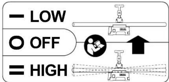
Figure 8 – Speed Label
LOW speed (I-Low switch setting). This decreases the risk of tube vibration and oscillation during use.
Recommended for tube 2" (50mm) diameter and smaller, and longer than 6.5' (2m)
HIGH speed (II-High switch setting). This will lower cutting time.
For tube larger than 2" (50mm) diameter of any length
For any tube shorter than 6.5' (2m)
Tube vibration and oscillation depend on many factors, such as the tube length, size, weight, straightness, stand alignment, roller speed, etc. If at any time you feel the tube is excessively vibrating or oscillating, release the foot switch. If in II-High speed, change to I-Low speed and try again. If in I-Low speed, change to another cutting method for that piece, such as a hand cutter.
To change speeds, release foot switch and allow cutter to come to a complete stop. Move switch to the desired position. Do not change operating speed while machine is running.
Cutting Tube
- Check that the tubing is not visibly bent and no fittings are attached. Cutting bent tubes or tubes with fittings can result in excessive vibration and loss of control. Use a hand cutter if needed. Mark the tubing at the desired length. For convenience, a measuring scale is provided on the machine.
- If needed, adjust the power tubing cutter size range with the quick switch size adjustment.
- Place the tubing on the rollers so that the cutting mark is located under the cutter wheel, on the zero mark of the scale. If the tubing extends beyond the machine, position supports under the tube. Supports should be adjusted so the tube sits squarely on the rollers. This will help insure proper tracking of the cut. See Figure 3.
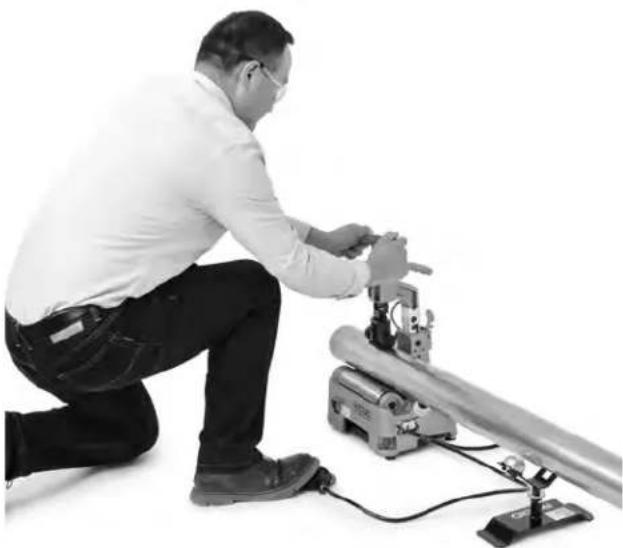
-
Assume a proper operating position to help maintain control of the machine and tube (see Figure 10):
-
Be sure you have convenient access to the tools and switch.
- Be sure that you can control the foot switch. Do not step on foot switch yet. In case of emergency, you must be able to release the foot switch.
-
Be sure that you have good balance and do not have to overreach.
-
Advance the quick feed system until the support rollers contact the tube (Figure 9). Align the cutter wheel with the mark on the tubing. Tighten the feed-screw to bring the cutter wheel in contact with the tube. After cutter wheel contacts tube, advance the feedscrew an additional 1 to 1 12 turns to grip the tube. Do not over advance the feedscrew, this can oval the pipe and increase burr formation.
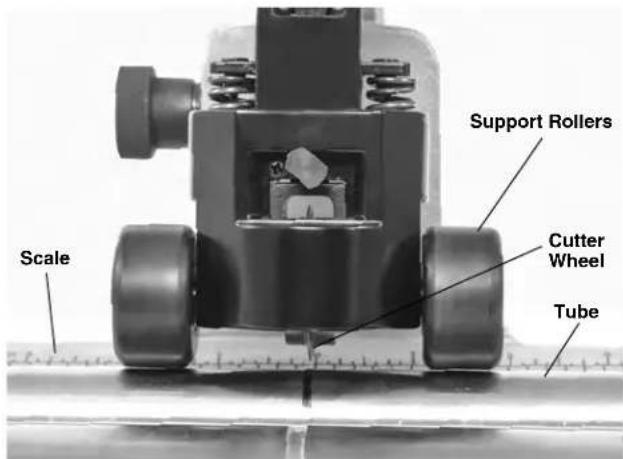
Figure 9 – Support Rollers Contacting Tubing
- Move the I-Low/O-OFF/II-High switch into the appropriate position for the tube being cut
- Depress the foot switch. The rollers and the tube will start to rotate. Keep hands way from rotating parts.
natural_image
Man kneeling beside a mechanical device with wires and components (no visible text or symbols)Figure 10 – Cutting Tubing
- Advance the feed screw by slowly and continuously tightening the feedscrew until the tubing is cut. Aggressive cutting can damage the cutter wheel and cause excessive burrs. Maintain the support rollers in contact with the tube to help hold the tube in place.
If the tubing spirals while being cut, stop the cut and check the machine set up, especially the alignment of the tube stands. Different tube materials may need slight additional tightening of the feedscrew to improve tracking.
- Remove foot from the foot switch. Then move the I-Low/O-OFF/I-High switch into O-OFF position.
- When tubing stops rotating, loosen the feedscrew 1-2 turns and press the release to fully retract the cutter wheel. Remove the tubing.
Reaming Tube

Figure 11 – Installing Reamer
- Place the I-Low/O-OFF/I-High switch in the O-OFF Position.
- Remove the reamer from the storage position and mount in use position as shown in Figure 11. Confirm that the reamer is securely mounted.
- Move the I-Low/O-OFF/I-High switch into I-Low position.
- Depress the foot switch. Keep hands away from tube ends and rotating parts.
- Securely grasp the tube. Properly support the tube to help maintain control.
- Place the tubing over the reamer cone and gently apply pressure (Figure 12) to remove burrs from inside of tube end. Do not force the tube into the reamer, this can cause the reamer to grab the tube and spin it in your hands.

natural_image
Industrial mechanical device labeled 'RIDGID' with cylindrical components and a long shaft (no visible text beyond label)Figure 12 – Reaming Tubing
- Remove foot from the foot switch.
- Place the I-Low/O-OFF/I-High switch in the O-OFF Position.
- Remove reamer from use position and return to storage position.
Transportation
- Remove or secure all loose equipment and material from the machine prior to moving to prevent falling or tipping.
- Place the cutter wheel in down position.
- Wrap the power cord and foot switch hose around the cord hook and secure as shown in Figure 13.
- Lift with grip. Use care in lifting and moving. Be aware of the machine weight.

natural_image
Mechanical pump with attached cable and handle, labeled 'Wheel Storage' (no other text or symbols visible)Figure 13 - Cord/Hose Wrapped
Storage
WARNING The Power Tubing Cutter must be kept dry and indoors or well covered if kept outdoors. Store the machine in a locked area that is out of reach of children and people unfamiliar with Power Tubing Cutter. This machine can cause serious injury in the hands of untrained users.
Maintenance Instructions
WARNING
Make sure that the switch is in the O-OFF position and the machine is unplugged before performing any maintenance or making any adjustments.
Maintain cutter according to these procedures to reduce the risk of injury from electrical shock, entanglement and other causes.
Cleaning
Gently clean the machine after each use with a clean dry cloth. Keep the rollers clean and free from dirt and debris.
Keep the reamer clean and free from chips for maximum efficiency.
Clean any dust and debris from the motor vents.
Lubrication
On a monthly basis (or more often if needed) lubricate all exposed moving parts of Power Tube Cutter and PC116TS stand (such as feed screw, quick feed system, rollers and pivot points) with a light lubricating oil. Wipe any excess oil from exposed surfaces.
Changing Cutter Wheel
See Specifications for proper cutting wheel selection. Change the cutter wheel when cutting different materials, replace the cutter wheel when the cutting edge becomes chipped or flat. An extra cutter wheel can be stored on the unit. See Figure 13.
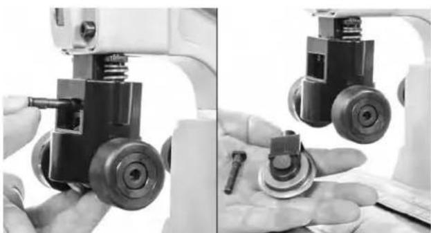
- Remove the link pin. The wheel holder will drop free (Figure 14).
natural_image
Close-up of a robotic arm with mechanical components, showing hands and a close-up of the base (no visible text or symbols)Figure 14 – Removing Wheel Holder
- Remove wheel pin and cutter wheel/bearing (Figure 15).
- Inspect bearing. Bearing should move freely. Replace if needed.
- Reverse process to install cutter wheel.
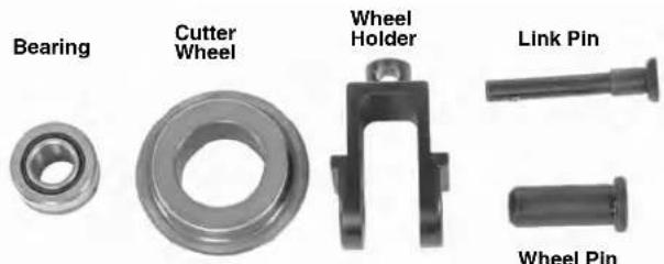
Figure 15 – Changing Cutter Wheel
Motor Overcurrent Protection
The cutter is equipped with overcurrent protection that turns off the machine to protect the motor if it draws excessive current.
If the machine shuts down unexpectedly, release the footswitch. Place the switch in the O-OFF position and unplug the machine. Remove any tube from the machine. Follow the Pre-Operation Inspection and Machine and Work Area Set-up sections to confirm that the machine works properly.
Changing Motor Brushes
Check motor brushes every six months, the brushes should be changed if the length is less than 5 mm (0.2").
- Confirm that switch is in the O-OFF position and the machine is unplugged.
- Loosen the five screws that hold the bottom cover (Figure 16) and remove cover (Some screws are retained to cover).
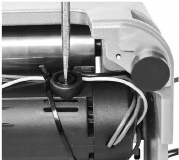
- Use a screwdriver to unscrew and remove the brush caps (Figure 17). Gently remove the carbon brushes and check the length (Figure 18). If brush length is less than 5 mm (0.2"), change brushes.
- Insert brush into brush holder, properly aligning the brush tabs with the reliefs in the brush holder.
- Securely tighten the brush caps. Reinstall the bottom cover.
- Once the machine is reassembled, run the machine in the II-High speed for five minutes with no tube in the machine to break in the brushes.
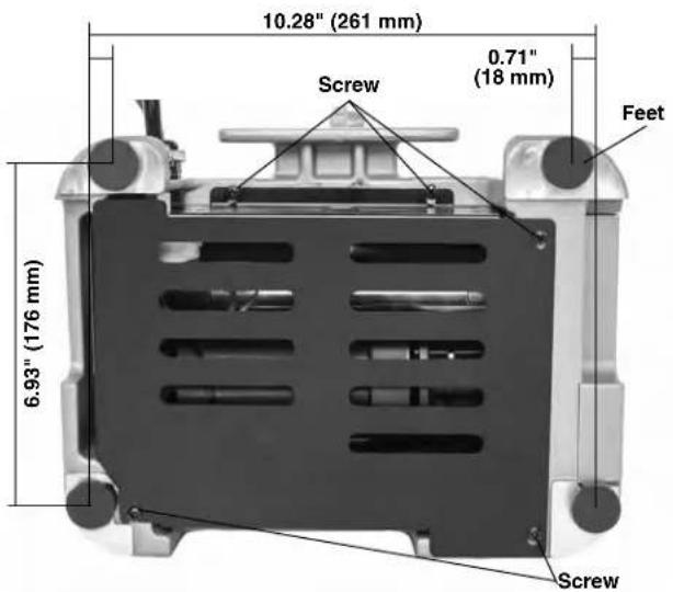
Figure 16 - Bottom Cover Screws
natural_image
Close-up of a mechanical assembly with wires and a screwdriver inserted into a cylindrical component (no visible text or symbols)Figure 17 – Removing Brush Cap
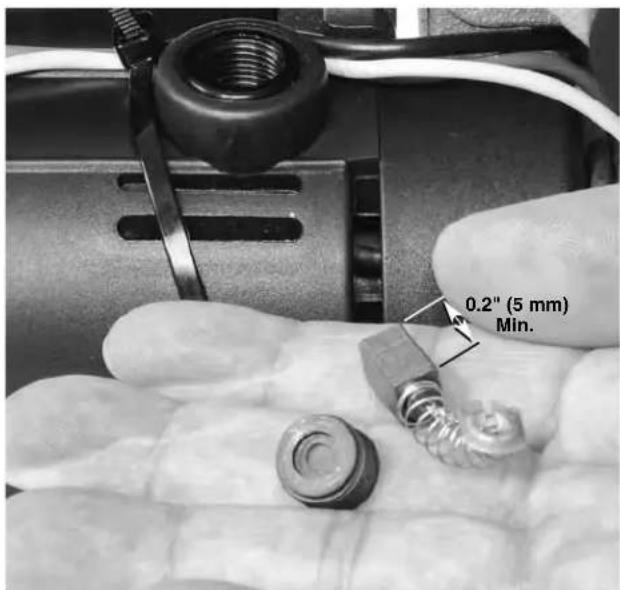
Figure 18 – Inspect Brush Length
Scan the QR code below to access the literature and video of PC116/PTC-400.

Troubleshooting
| PROBLEM POSSIBLE REASONS SOLUTION | ||
| Excessive vibration during operation. | Wrong operating speed.Cutting bent tube.Long tube not properly supported.Machine not properly mounted. | See Selecting Operating Speed.Do not cut visibly bent tube. Use hand cutter.Support long tube with pipe stands.Properly mount the machine on flat surface, bolt with the mounting bolts. |
| Machine not cutting tubes properly. | Worn cutter wheel.Use on incorrect tube size or material. | Replace worn cutter wheel.Use on correct type of tube (see Specifications). |
| Machine stalls while cutting. | Agressive feeding of the cutter wheel while cutting | Gently feed the cutter wheel. |
| Machine does not operate. | Motor brushes are worn out.Overcurrent protection activated. | Install new motor brushes.Follow Motor Overcurrent instructions in Maintenance section. |
| Excessive tube burrs or end deformation. | Worn or damaged cutter wheel.Agressive feeding of the cutter wheel while cutting | Replace cutter wheel.Gently feed the cutter wheel. |
| Machine stops while foot switch is depressed. Re-starts when foot switch is re-depressed. | Hole in foot switch/hose.Air switch leaks. | Replace foot switch.If no issue found with foot switch/hose, have air switch replaced. |
Service and Repair
WARNING
Improper service or repair can make the machine unsafe to operate.
The Maintenance Instructions will take care of most of the service needs of this machine. Any problems not addressed by this section should only be handled by a RIDGID Independent Service Center. Use only RIDGID service parts.
For information on your nearest RIDGID Independent Service Center or any service or repair questions see Contact Information section in this manual.
Optional Equipment
WARNING
To reduce the risk of serious injury, only use accessories specifically designed and recommended for use with the RIDGID PC116/PTC-400 Power Tubing Cutter, such as those listed.
| CatalogNo. | Description |
| 64903 | PC116TS Tube stand for use with PC116/PTC-400 |
| 66253 | PC116 220-240V Motor carbon brush |
| 66248 | PC116 100-120V Motor carbon brush |
| 56662 | VJ-99 28" - 52" V-Head High Pipe Stand |
| 64908 | 137S Reamer for PC116/PTC-400 |
| 66938 | E850 Cutter Wheel (For Metallic Tube) |
| 66943 | E855 Cutter Wheel (For Plastic Tube) |
| 64898 | Cutter Wheel Bearing |
For a complete listing of RIDGID equipment available for these tools, see the Ridge Tool Catalog online at RIDGID.com or see Contact Information.
Disposal
Parts of these tools contain valuable materials and can be recycled. There are companies that specialize in recycling that may be found locally. Dispose of the components in compliance with all applicable regulations. Contact your local waste management authority for more information.

For EC Countries: Do not dispose of electrical equipment with household waste!
According to the European Guideline 2012/ - 19/EU for Waste Electrical and Electronic Equipment and its implementation into national legislation, electrical equipment that is no
longer usable must be collected separately and disposed of in an environmentally correct manner.
Coupe-tubes
natural_image
Ridgid industrial machine with handle and control panel, no visible text or symbols on the device itself.
AVERTISSEMENT !
tube maxi....20' (6m)
Moteur
Type ....Universel
Tension
Poids ......32 lbs. (14,5 kg)
(L x I x H)....11,6" × 9,4" × 15,9"
(295 mm × 239 mm × 403 mm)
natural_image
Experimental setup with a tripod-mounted tool and a cylindrical apparatus mounted on a flat base (no visible text or symbols)natural_image
Three-step mechanical assembly diagram showing hand positioning and tool movement (no text or symbols)Figure 7 – Engagement rapide : A-Engagement, B-Desserrage, C-Dégagement
natural_image
Man kneeling beside a mechanical device with wires, no visible text or symbolsnatural_image
Close-up of a hand holding a metallic cylindrical object, next to a mounted optical instrument (no visible text or symbols)natural_image
Industrial mechanical device labeled 'RIDGID' with no visible text or symbols on the device itself.natural_image
Close-up of hands operating a mechanical device with a small tool, no visible text or symbolsnatural_image
Close-up of an electric motor with visible wiring and a screwdriver inserted (no text or symbols)Dépannage
natural_image
Ridgid industrial machine with handle and control panel, no visible text or symbols on the device itself.
ADVERTENCIA
natural_image
Experimental setup with a long cylindrical apparatus mounted on a base, connected to a tripod and a small sensor device (no visible text or symbols)natural_image
Three-step mechanical assembly diagram showing hand positioning and force application (no text or symbols)Figura 8 – Etiqueta de velocidades
natural_image
Man kneeling and working on a mechanical device with wires and tools (no visible text or symbols)natural_image
Industrial mechanical device labeled 'RIDGIO' with cylindrical components and a shaft (no readable text beyond branding)Figura 12 – Escariado del tubo
natural_image
Close-up of hands operating a mechanical device with a small tool inserted (no visible text or symbols)natural_image
Close-up of an electric motor with visible wiring and a screwdriver inserted (no text or symbols)natural_image
Ridgid industrial machine with handle and control panel, no visible text or symbols on the device itself!WARNUNG!
natural_image
Experimental setup with a tripod-mounted tool and a cylindrical apparatus mounted on a flat base (no visible text or symbols)natural_image
Three-step mechanical assembly diagram showing hand positioning and rotation of a clamping device (no text or symbols)natural_image
Man kneeling beside a mechanical device with wires, no visible text or symbolsnatural_image
Industrial mechanical device labeled 'RIDGID' with cylindrical components and a long shaft (no visible text or symbols beyond branding)natural_image
Industrial machine with hoses and control lever (no visible text or symbols)natural_image
Close-up of hands operating a mechanical device with a small tool, no visible text or symbolsnatural_image
Close-up of an electric motor with visible wiring and a screwdriver inserted (no text or symbols)Fehlerbehebung
NOTE: This equipment has been tested and found to comply with the limits for a Class A digital device, pursuant to part 15 of the FCC Rules. These limits are designed to provide reasonable protection against harmful interference when the equipment is operated in a commercial environment. This equipment generates, uses, and can radiate radio frequency energy and, if not installed and used in accordance with the instruction manual, may cause harmful interference to radio communications. Operation of this equipment in a residential area is likely to cause harmful interference in which case the user will be required to correct the interference at his own expense.
RIDGE TOOL COMPANY Ridge Tool Europe NV (RIDGID)
Elyria, Ohio 44035-6001
U.S.A.
3800 Sint-Truiden
Belgium
EC DECLARATION OF CONFORMITY
We declare that the machines listed above, when used in accordance with the operator's manual, meet the relevant requirements of the Directives and Standards listed below.
DÉCLARATION DE CONFORMITÉ CE
DEKLARACJA ZGODNOŚCI WE
Qualification: V.P. Engineering
Date: 12/01/2020

Intertek
Conforms to UL 62841-1
Certified to CSA C22.2#62841-1-15, 45CFR15B/ICES 003
What is covered
RIDGID ^® tools are warranted to be free of defects in workmanship and material.
How long coverage lasts
This warranty lasts for the lifetime of the RIDGID ^® tool. Warranty coverage ends when the product becomes unusable for reasons other than defects in workmanship or material.
How you can get service
To obtain the benefit of this warranty, deliver via prepaid transportation the complete product to RIDGE TOOL COMPANY, Elyria, Ohio, or any RIDGID® AUTHORIZED INDEPENDENT SERVICE CENTER. Pipe wrenches and other hand tools should be returned to the place of purchase.
What we will do to correct problems
Warranted products will be repaired or replaced, at RIDGE TOOL'S option, and returned at no charge; or, if after three attempts to repair or replace during the warranty period the product is still defective, you can elect to receive a full refund of your purchase price.
What is not covered
Failures due to misuse, abuse or normal wear and tear are not covered by this warranty. RIDGE TOOL shall not be responsible for any incidental or consequential damages.
How local law relates to the warranty
Some states do not allow the exclusion or limitation of incidental or consequential damages, so the above limitation or exclusion may not apply to you. This warranty gives you specific rights, and you may also have other rights, which vary, from state to state, province to province, or country to country.
No other express warranty applies
This FULL LIFETIME WARRANTY is the sole and exclusive warranty for RIDGID® products. No employee, agent, dealer, or other person is authorized to alter this warranty or make any other warranty on behalf of the RIDGE TOOL COMPANY.

Parts are available online at Store.RIDGID.com
Ridge Tool Company
400 Clark Street
Elyria, Ohio 44035-6001
U.S.A.
Ce qui est couvert
Printed 2/21 944-732-258.10
EC44721/02 REV. C
©2021 Ridge Tool Company. All rights reserved
RIDGID and the Emerson logo are registered trademarks of Emerson Electric Co. or its subsidiaries in the US and other countries.
Any other trademarks belong to their respective holders.


- PC116/PTC-400 Power Tubing Cutter
- Table of Contents
- General Power Tool Safety Warnings
- Maintenance Instructions
- Tubing Cutter
- WARNING!
- Safety Symbols
- DANGER
- WARNING
- CAUTION
- NOTICE
- General Power Tool Safety Warnings\*
- SAVE ALL WARNINGS AND INSTRUCTIONS FOR FUTURE REFERENCE!
- Work Area Safety
- Electrical Safety
- Personal Safety
- Power Tool Use and Care
- Service
- Specific Safety Information
- RIDGID Contact Information
- Description
- Specifications
- Standard Equipment
- Assembly
- Bench Mounting
- Pre-Operation Inspection
- Machine and Work Area Set-Up
- PC116TS Stand/Adjustment
- Operating Instructions
- Adjusting Cutter For Different Tube Sizes Quick Switch Size Adjustment
- Quick Feed Cutter Adjustment
- Selecting/Changing Operating Speed
- Cutting Tube
- Transportation
- Storage
- Cleaning
- Lubrication
- Changing Cutter Wheel
- Motor Overcurrent Protection
- Changing Motor Brushes
- Service and Repair
- Optional Equipment
- Disposal
- Coupe-tubes
- AVERTISSEMENT !
- ADVERTENCIA
- !WARNUNG!
- EC DECLARATION OF CONFORMITY
- DÉCLARATION DE CONFORMITÉ CE
- DEKLARACJA ZGODNOŚCI WE
- What is covered
- How long coverage lasts
- How you can get service
- What we will do to correct problems
- What is not covered
- How local law relates to the warranty
- No other express warranty applies
- Parts are available online at Store.RIDGID.com
- Ridge Tool Company
- Ce qui est couvert
Brand : RIDGID
Model : PTC400
Category : Slicer