GSB 20/12 R - Drill Güde - Free user manual and instructions
Find the device manual for free GSB 20/12 R Güde in PDF.

User questions about GSB 20/12 R Güde
0 question about this device. Answer the ones you know or ask your own.
Ask a new question about this device
Download the instructions for your Drill in PDF format for free! Find your manual GSB 20/12 R - Güde and take your electronic device back in hand. On this page are published all the documents necessary for the use of your device. GSB 20/12 R by Güde.
USER MANUAL GSB 20/12 R Güde
natural_image
Icon of an open book inside a black circle (no text or symbols)Deutsch DE 2
Originalbetriebsanleitung
TISCHBOHRMASCHINE
English GB 17
Translation of original operating instructions
BENCH DRILL
Français F 35
PERCEUSE D'ETABLI
Čeština CZ 53
STOLNÍ VRTAČKA
Slovenčina SK 71
Nederlands NL 89
Italiano I 107
Traduction du mode d'emploi d'origine
Překlad originálního návodu k provozu
Preklad originálneho návodu na prevádzku
WIERTARKA STOTOWA
Vertaling van de originele gebruiksaanwijzing
TAFELBOORMACHINE
Traduzione del Manuale d'Uso originale
TRAPANO DA BANCO
Magyar H 125
Az eredeti használati utasítás fordítása
ASZTALI FÚRÓGÉP
Slovenščina SLO 143
Prevod originalnih navodil za uporabo
NAMIZNI VRTALNIK
Hrvatski HR 161
Prijevod originalnih uputa za uporabu
STOINA BUŠILICA
Bosanski BIH 179
Prijevod originalnih uptstava za upotrebu.
STOLNA BÜŠILICA
Românește RO 197
Traducerea manualului de exploatare original
MASINA DE GAURIT CU MASA
Български BG 215
Превод на оригиналната инструкция
Настолна бормашина
GTB 13
55120
GTB 16
55190/55192
GTB 20
55193/55194
natural_image
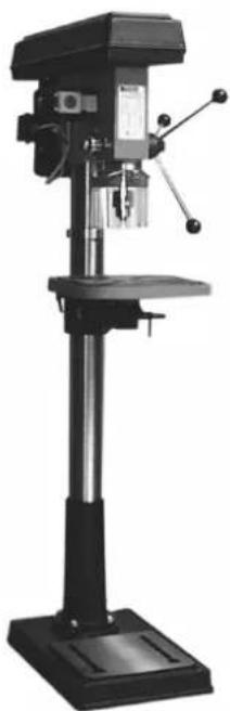
Black-and-white photo of a drill press machine with no visible text or symbols
natural_image
Industrial drill press machine with adjustable arms and base (no visible text or labels)
natural_image
Industrial drill press machine with adjustable arm and base (no visible text or labels)
natural_image
Industrial drill press machine with adjustable arms and base (no visible text or labels)GSB 20
55195/55197
natural_image
Industrial drill press machine with adjustable arms and base (no visible text or labels)GSB 25 R+L
55423

natural_image
Industrial drill press machine with metal frame and control panel (no visible text or labels)GSB 32 R+L
55435
Technische Daten
Modell GTB 13 GTB 16/5 GTB 16/5 R+L GTB 20/12 GTB 20/12 R+L
text_image
Technical diagram of a mechanical assembly with numbered parts, likely an engine or drill press system.Montage
natural_image
Line drawings of four different wrenches and tools (no text or labels)Abb. 2
natural_image
Technical line drawing of a mechanical device with mounting base and cylindrical components (no text or symbols)A b b . 3
text_image
Technical diagram of a mechanical assembly with numbered components and cross-sectional viewsA

text_image
Technical diagram of a mechanical device with numbered parts labeled 1, 2, and 3.A b b . 5
text_image
1 2 3 4 5Abb. 6
text_image
Technical diagram of a mechanical assembly with labeled parts 1 and 2A
b
b
7
text_image
Technical diagram of a mechanical clamp or bracket assembly with labeled parts 1 and 2A
natural_image
Technical line drawing of an industrial machine with control panel and wiring (no text or symbols)A
b
b
9
text_image
Technical diagram of a mechanical assembly with labeled parts 1 and 2A
text_image
Technical diagram of a mechanical device with numbered components and an inset view showing a cylindrical component.Abb. 13
text_image
Technical diagram showing a mechanical assembly with labeled components and an inset view of a component.Abb. 14
Einstellungen
text_image
Technical diagram of a mechanical device with labeled components and directional arrows indicating motion or flow.Abb. 16 Abb. 17

text_image
Technical diagram of a mechanical assembly with numbered components for identificationEC Declaration of Conformity
that the following Appliance complies with the appropriate basic safety and health requirements of the EC Directive based on its design and type, as brought into circulation by us.
In a case of alternation of the machine, not agreed upon by us, this declaration will lose ist validity.
Machine Description:
Applicable EC Directives: - 2006/42/EG
In the drill belt enclosure, a safety switch is fitted. The machine will not start when the enclosure cover is opened or not properly closed.
Always check this microswitch functioning when you experience troubles at start-up. However, never leave the machine on when handling this microswitch manually. That could result in serious injury.
!
List of Contents
ARTICLE Page
- Technical Data....17
- General Safety Precautions....18
- Other General Safety Precautions....18
- Drills-Specific Safety Precautions....19
- Electrical Part Information....20
- Meet Your Drill....21
- Assembling....22
- Adjustment....28
- Operation....30
- Maintenance ....30
- Drilling Specifications Table....31
- Machine Exploded View Drawing....32
- List of Spare Parts for GTB 13....33
- List of Spare Parts GTB 16. GTB 20. GSB 20. GSB 25 R+L. GSB 32 R+L....34
- Pack Sheet GTB 13....35
- Pack Sheet GTB 16. GTB 20. GSB 20. GSB 25 R+L. GSB 32 R+L....35
1. Technical Data
Model GTB 13 GTB 16/5 GTB 16/5 R+L GTB 20/12 GTB 20/12 R+L
| Supply voltage: | 230 V/50 Hz | 230 V | 400 V | 230 V | ||
| Motor capacity: | 180 W | 600 W | 600 W | 800 W | ||
| Chuck: | 13 mm | 16 mm | 16 mm | 16 mm | ||
| Quill stroke: | 50 mm | 60 mm | 60 mm | 80 mm | ||
| Taper attachment: | MK 1/B16 | MK 2 | MK 2 | MK 2 | ||
| Reach: | 105 mm | 126 mm | 126 mm | 178 mm | ||
| Bench size: | 164 x 164 mm | 200 x 195 mm | 200 x 195 mm | 300 x 300 mm | ||
| Base plate size: | 295 x 185 mm | 348 x 210 mm | 348 x 210 mm | 456 x 270 mm | ||
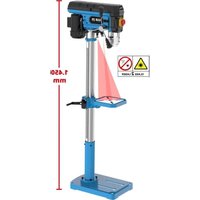
| Total height: | 580 mm | 840 mm | 840 mm | 1065 mm | ||
| Quill speed: | 500-2500 rpm. | 5 dg | 12 dg | 12 dg | ||
| 460-2480 rpm | 230-2470 rpm | 180-2740 rpm | ||||
| Ordering No.: | 55120 | 55190 | 55192 | 55193 |
| Model | GSB 20/12 | GSB 20/12 R+L | GSB 25 R+L | GSB 32 R+L |
| Supply voltage: | 230 V | 400 V | 400 V | 400 V |
| Motor capacity: | 600 W | 800 W | 1100 W | 1500 W |
| Chuck: | 16 mm | 16 mm | 3-16 mm | 3-16 mm |
| Taper attachment: | MK 2 | MK 2 | MK 3/B16 | MK 3 |
| Quill stroke: | 80 mm | 80 mm | 120 mm | 120 mm |
| Reach: | 178 mm | 178 mm | 210 mm | 255 mm |
| Bench size: | 300 x 300 mm | 300 x 300 mm | 335 x 335 mm | 423 x 475 mm |
| Base plate size: | 456 x 270 mm | 456 x 270 mm | 520 x 305 mm | 450 x 580 mm |
| Total height: | 1610 mm | 1610 mm | 1670 mm | 1720 mm |
| Quill speed: | 12 dg | 12 dg | 16 dg | 12 dg |
| 180-2740 rpm | 180-2740 rpm | 160-3000 rpm | 110-2.880 rpm | |
| Ordering No.: | 55195 | 55197 | 55423 | 55435 |
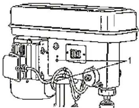
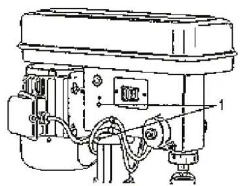
2. Microswitch Safety Device
In the drill belt enclosure, a safety switch is fitted. The machine will not start when the enclosure cover is opened or not properly closed.
Always check this microswitch functioning when you experience troubles at start-up. However, never leave the machine on when handling this microswitch manually. That could result in serious injury.
!
4. Drills-Specific Safety Precautions
WARNING: DO NOT OPERATE THE MACHINE BEFORE IT IS COMPLETELY ASSEMBLED AND INSTALLED IN COMPLIANCE WITH INSTRUCTIONS.
- NEVER SWITCH THE DRILL ON BEFORE YOU REMOVE ANY OBJECTS FROM THE BENCH (tools, wastes etc.).
- NEVER put your hands and finger close to the drill bit.
- DO NOT ATTEMPT to drill material with the surface other than flat unless a suitable support is available.
- NEVER switch the machine on while pressing the drill bit against the material.
- Before switching the machine on, MAKE SURE that the bench-clamping lever is firmly tightened.
- NEVER draw anything on the piece to be drilled, do not mount, do not clamp the material on the bench while the machine is running.
- MAKE SURE that the bit is firmly clamped in the chuck.
- Before switching the machine on, MAKE SURE that the chuck key is removed.
- ADJUST the bench or the down stop to avoid drilling in the bench.
- ALWAYS stop the bit before removing chips from the bench.
- USE A CLIP OR CLAMPING JAWS to secure the piece to be drilled on the bench.
- DON'T wear gloves when operating the drill.
- Before leaving the machine, PUT THE CURRENT SUPPLY OFF, remove the bit and clean the bench.
- Set the drill to speed answering a specific job. .
- If a part of the drill is missing, found damaged or id an electrical component does not work properly, switch the current supply off and pull the cable out of the socket. Replace the missing, damaged or not working components and only then resume the machine operation.
Follow the above safety regulations!!
5. Electrical Part Information
Grounding Instructions
IN CASE OF FAULT OR OUTAGE, grounding guarantees the current the least resistance passage and reduces the risk of electrical shock. This machine has a power cable fitted with grounding conductor and grounding plug.
The plug MUST be inserted in the interconnecting socket conforming to ANY local regulations and properly installed and grounded in compliance with the same.
DO NOT ALTER THE PLUG SUPPLIED IN ANY WAY. If it does not fit in your socket, have a matching socket installed by a qualified electrician.
UNQUALIFIED CONNECTION of the grounding conductor may entail a risk of electrical shock. The green-insulated conductor (with/without yellow stripes) is the grounding conductor. If repair or replacement of the power cable or the plug is required, DO NOT CONNECT the grounding conductor to the conductive input terminal.
If you do not quite understand grounding instruction or if you are not sure that the machine is grounded as appropriate, invite a qualified electrician or a servicing staff to CHECK the grounding conductors.
CAUTION: IF IN DOUBT ON YOUR SOCKET APPROPRIATENESS, MAKE SURE THAT IT IS GROUNDED AS REQUIRED. IF YOU ARE NOT SURE, HAVE IT CHECKED BY A QUALIFIED ELECTRICIAN.
WARNING: THIS DRILLING MACHINE IS DESIGNED FOR WORKING INDOORS ONLY. NEVER EXPOSE IT TO RAIN AND DO NOT USE IT IN ANY WET AREAS.
WARNING: THE MACHINE IS PERMITTED FOR OPERATION PROVIDED THAT IT IS CONNECTED TO A VOLTAGE SOURCE USING A FAULT CURRENT PROTECTION SWITCH.
Make sure that the extension cable working condition is good. Provided that an extension cable be used, make sure that the cross-section of it is sufficient for it to conduct the current needed for the product. An undersized extension cable will cause a voltage drop resulting in the current loss and overheating. The table below shows the correct sizes to be used subject to the cable length and the current value shown on the plate. If in doubt, use the nearest bigger size.
The extension cable sizes show in the table will provide against a voltage drop above 5% at an estimated load.
| Current(plate value) | 3 | 6 | 10 | 12 | |
| Extension cable length | Conductor cross-section mm | ^2 | |||
| 7.5 m | 0.75 | 0.75 | 1.0 | 1.25 | |
| 15 m | 0.75 | 0.75 | 1.0 | 1.5 | |
| 22.5 m | 0.75 | 0.75 | 1.0 | 1.5 | |
| 30 m | 0.75 | 0.75 | 1.25 | 1.5 | |
| 45 m | 0.75 | 1.25 | 1.5 | 2.5 | |
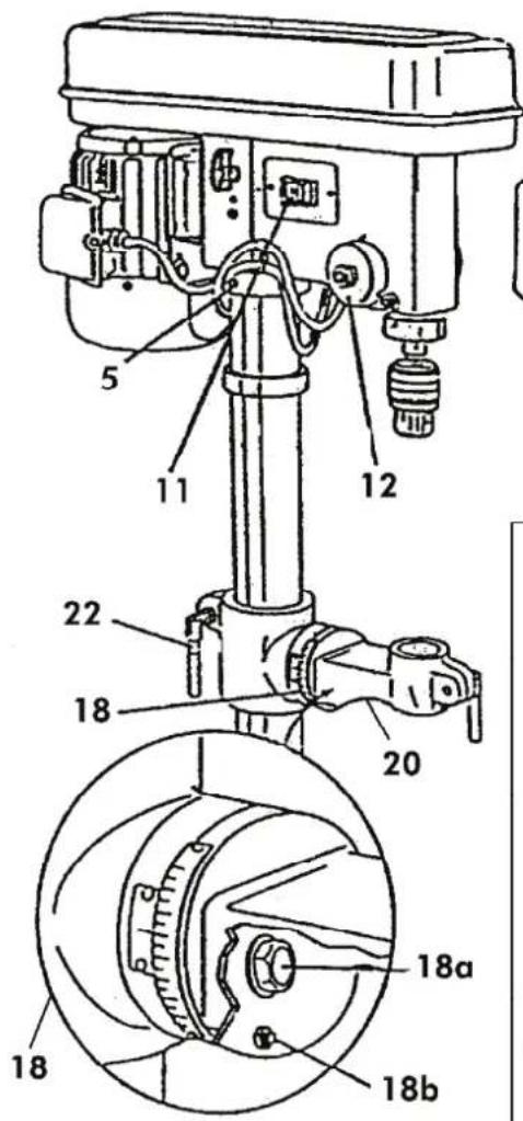
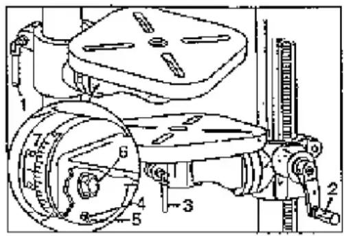
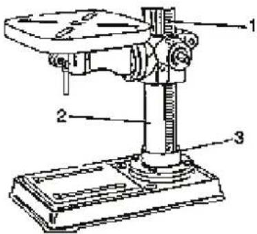
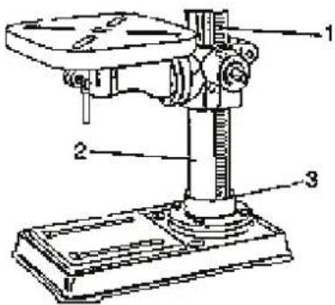
6. Meet Your Drill
1 - Rotation speed indication 18 - Pitch adjustment scale
2 - Screw 18a - Setting screw
3 - Drill depth adjustment scale 18b - Nut
4 - Scale pointer 19 - Knockout wedge
5 - Set screw
6 - Quill pulley 21 - Quill bushing
7 - Guide wheel 22 - Bench clamp tightening lever
8 - Motor pulley 23 - Column
9 - Down stop 24 - Bench crank
10 - Motor clamping lever 25 - Bench arm tightening lever
11 - Speed control knob 26 - Taper drift
12 - Quill return spring 27 - Mounting holes
13 - Quill (assembly) 28 - Rack
14 - Chuck 29 - Chuck
15 - Rack ring 30 - Base plate
16 - Bench 31 - Chuck tightening key
17 - Advancement hand lever 32 - Bench bracket
text_image
5 11 12 22 18 20 18a 18 18b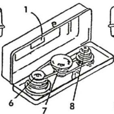
text_image
Technical diagram of an electrical switch or relay with numbered components labeled 1 through 8
text_image
13 19 21 26 29 31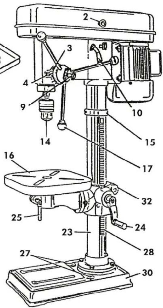
text_image
Technical diagram of a drill press with numbered parts for identification7. Assembling
Assembling and Cleaning
Carefully unpack the drill and all the parts and compare against the list below. Do not throw away the carton and wrapping until the drill press is completely assembled.
Any worked surface is treated with protective coating to protect the machine against moisture. Remove the coating using a soft cloth wetted with kerosene or WD-40 agent. Never use acetone, petrol or solvents for CLEANING.
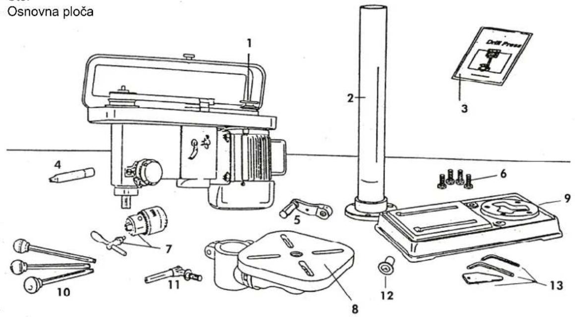
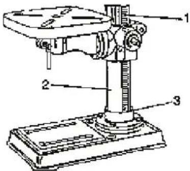
Parts Fig. 1
1 - Motor assembly 10 - Stems/advancement lever
2 - Column 11 - Column lock lever
3 - Service instruction (manual) 12 - Top knob
4 - Tapered drift 13 - 2 hex-wrenches & cotter
5 - Bench crank
6 - Screws/bolts
7 - Chuck and chuck key
8 - Bench
9 - Base plate

text_image
Technical diagram of a mechanical assembly with numbered components and labeled partsFig. 1
Fig. 1
Warning: If a part is missing or found damaged, do not connect the drill to the voltage source until the missing or defective part is replaced and the assembly completed.
natural_image
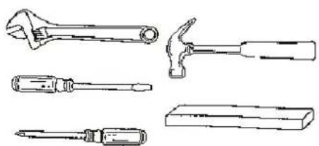
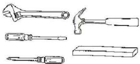
Line drawings of four different wrenches and screwdrivers (no text or labels)Fig. 2
Assembly tooling:
- Monkey wrench
- Screwdriver*
- Hammer and a piece of wood
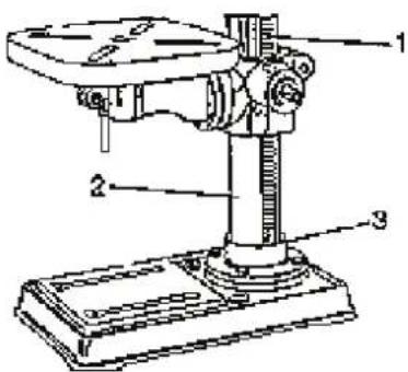
Column Base Plate Assembling (Fig. 3)
- Align the column to the holes in the base plate.
- Insert screw 10mm x 25mm in each hole of the column.
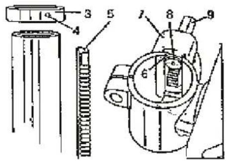
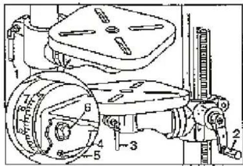
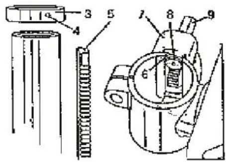
Mounting Bench on Column (Fig. 3)
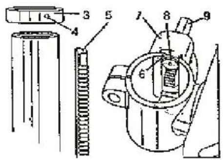
- Slacken the setting screw (4) to remove the ring (3).
- Remove the rack from the column (5).
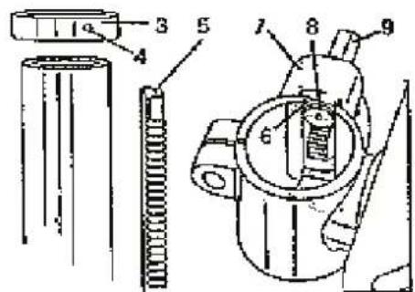
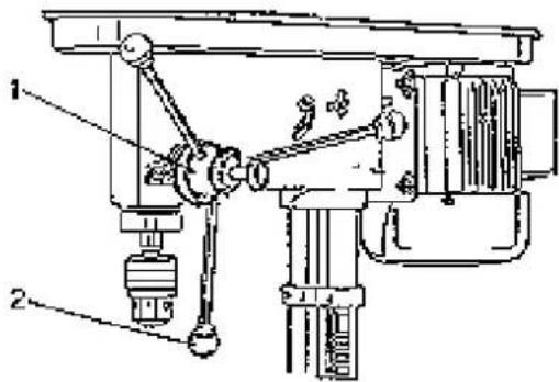
- Check the worm gear (8) to see whether it is properly inserted in the bench fastening arm (7) and it touched the gear wheels. The stem (9) should protrude ca 2.5 cm from the box (Fig. 4).
- Insert the rack (5) in the cross groove (6) of the bench-fastening arm (7) (Fig. 4).
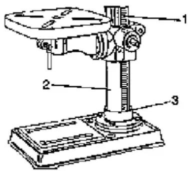
The bench fastening arm should be seated in the rack middle section. - Carefully slide the bench fastening arms and the rack (1) on the column (2) (Fig. 5). Insert the rack lower part in the slot of (3) the column base plate.
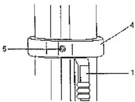
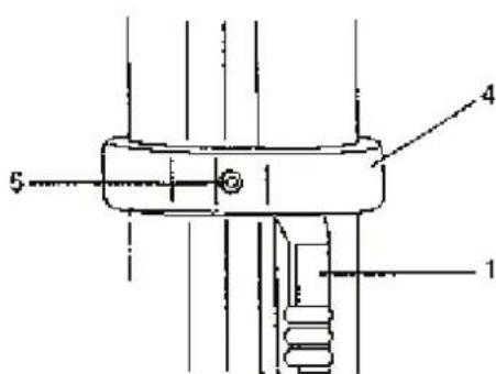
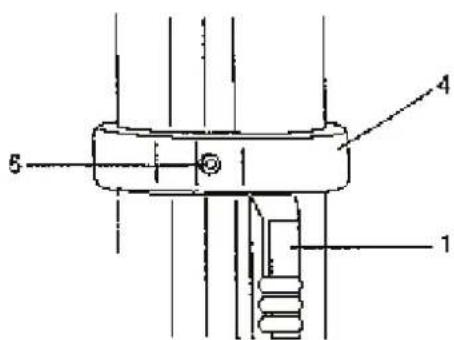
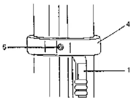
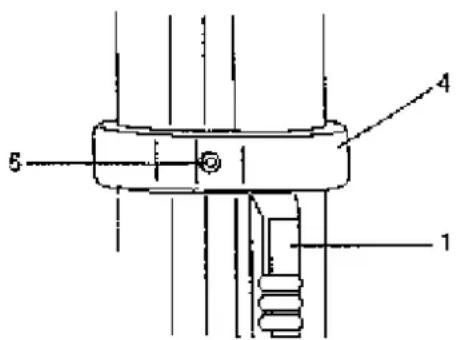
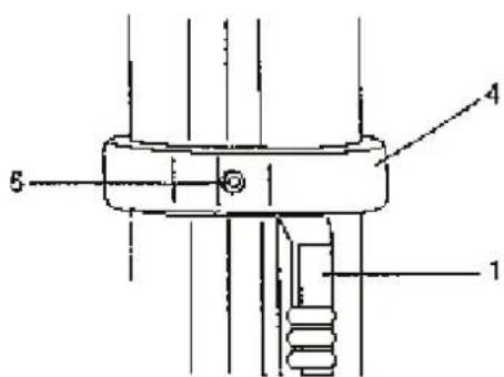
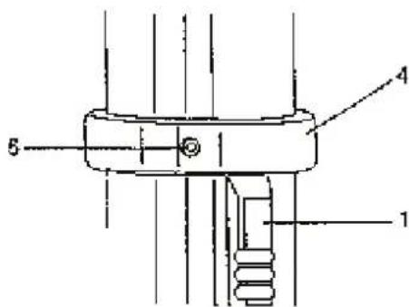
- Hold the fastening arm and the rack against the column (Fig. 6) and slide the rack ring (4) on the column.
- The rack (1) will just fit in the ring (4). Make sure that there is sufficient clearance between the rack and the ring so that the bench may rotate around the column.
- Tighten the set screw (5). to fix the ring position.
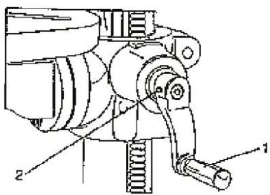
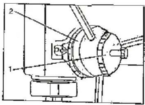
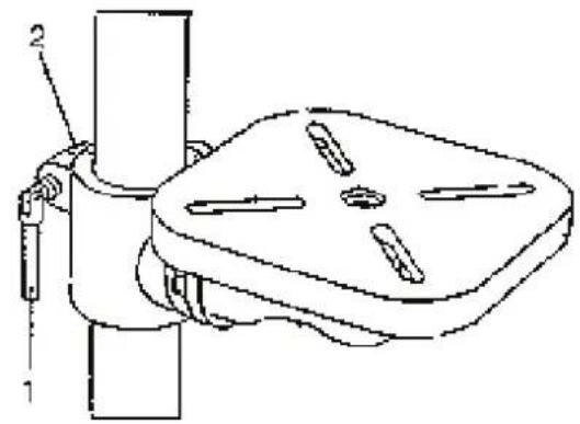
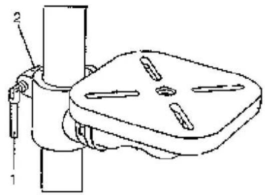
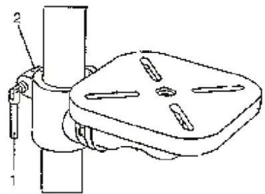
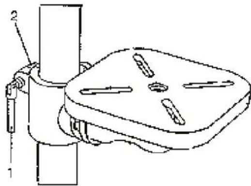
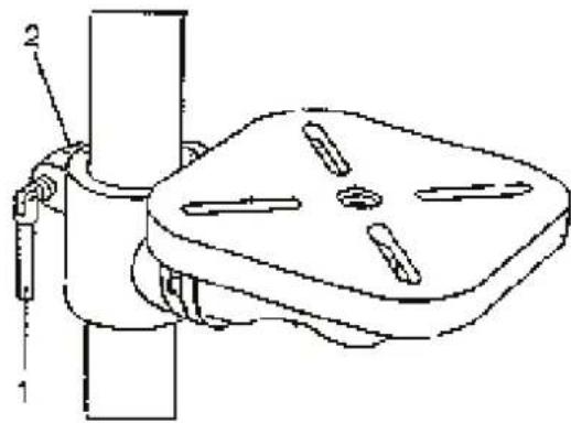
- Fit the handgrip (1) in place and tighten the setscrew (2). (Fig. 7)
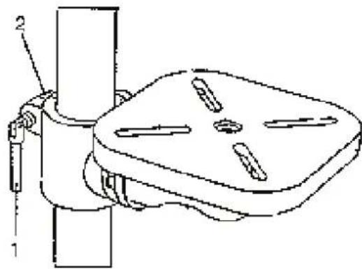
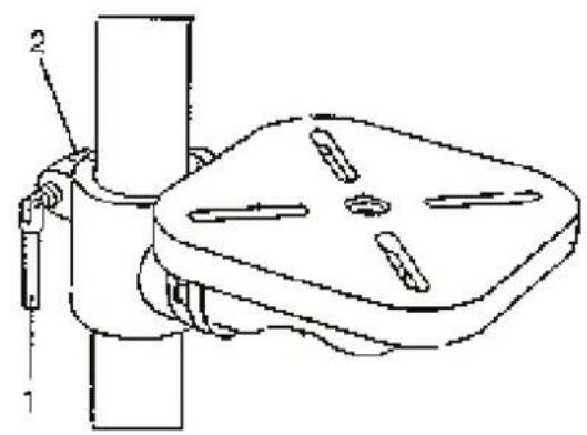
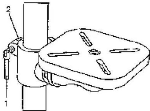
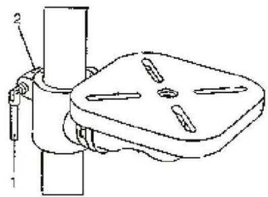
- Slide the column-locking lever (1) in the bench-fastening arm (2) (Fig. 8)
- Rotate the bench and adjust it so that it is above the base plate and it stays in alignment with it
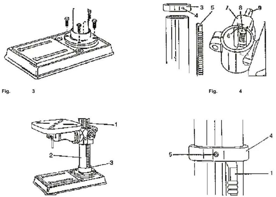
Fig. 5
Fig. 6
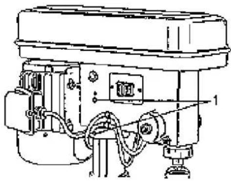
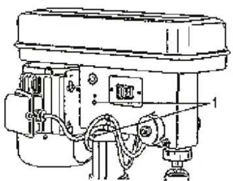
Fixing Drill Head on Column
- Carefully lift the drill head above the column. If the head is too heavy for you to handle, the work will take two.
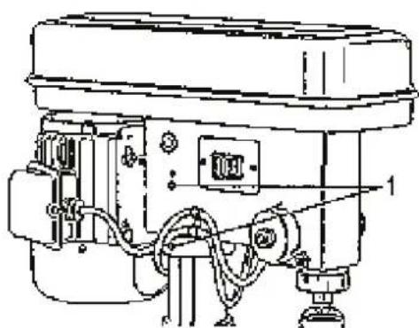
- The column fits in the drill mounting hole. Make sure that the mounting hole is seated on the column. Align the drill head with the bench and the base plate and tighten the two setscrews using a hex wrench. (Fig. 9)
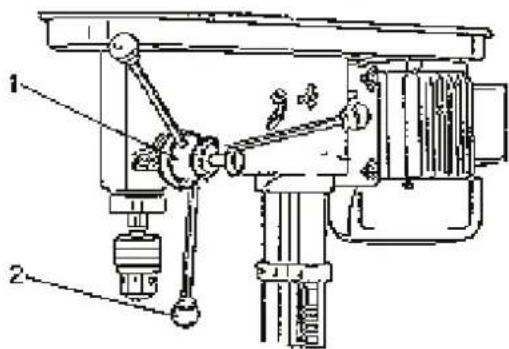
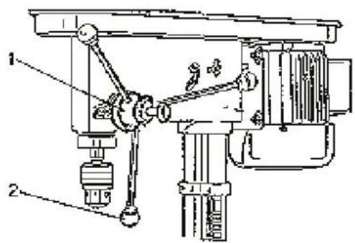
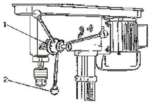
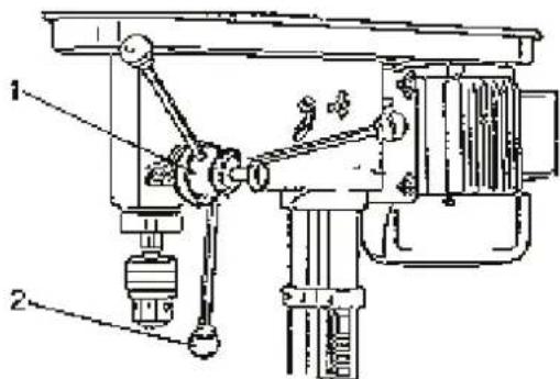
Advancement Hand Lever Assembling (Fig. 10)
- Screw three bars in the advancement lever (1).
- Tighten the round knobs (2) at the ends of the bars.
text_image
Technical diagram of a mechanical assembly with labeled parts 1 and 2Fig. 7
text_image
Technical diagram of a mechanical clamp or bracket with labeled parts 1 and 2Fig. 8
natural_image
Technical line drawing of an industrial machine with control panel and wiring (no text or symbols)Fig. 9

text_image
Technical diagram of a mechanical assembly with labeled parts 1 and 2Fig. 10
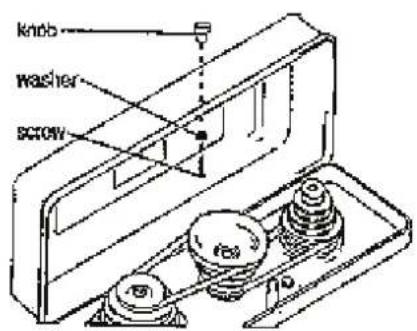
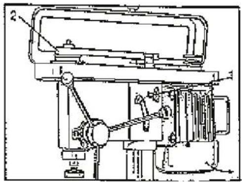
Pulleys Housing Assembling (Fig. 11)
- Push a washer and a screw trough the pulley housing hole.
- Screw on the knob and tighten it.
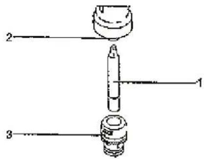
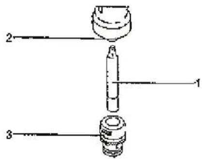
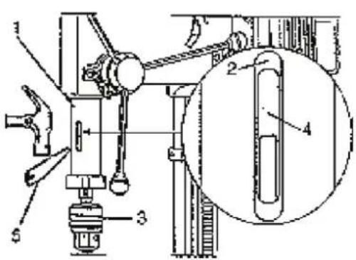
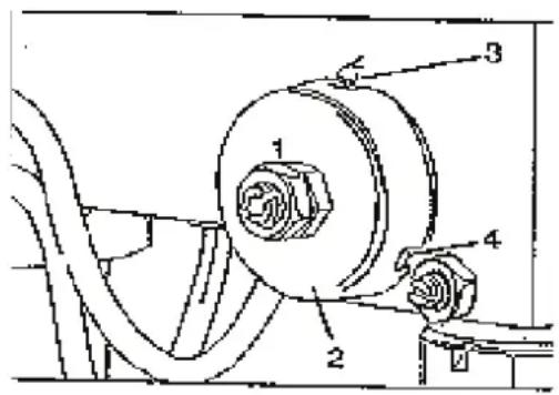
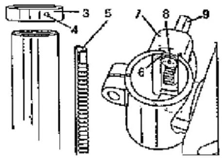
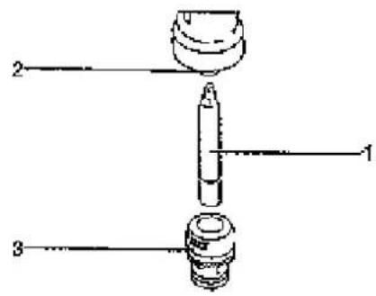
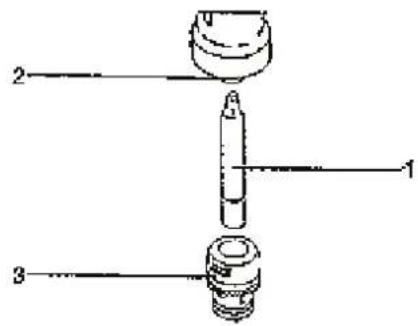
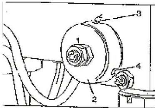
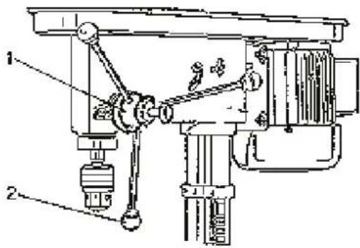
Shaft and Chuck Assembling (Fig. 12)
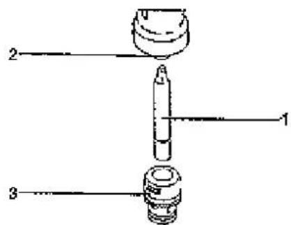
- Carefully clean the Morse taper and the chuck and keep them free of any traces of oil and dust. Now, fit the Morse taper (1) in the chuck (2) with a jerk.
- Put the chuck (3) on the taper drift short cone.
- Close the chuck jaws completely. To prevent any damage to the chuck. put a small spanner in and knock the taper and the chuck up with 2-3 slight hits.
WARNING: To avoid any damage to the chuck. do not use metal hammer for hammering the chuck on the shaft.
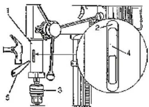
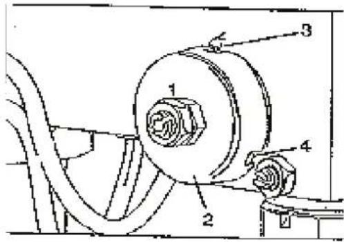
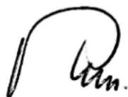
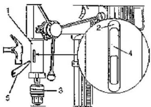
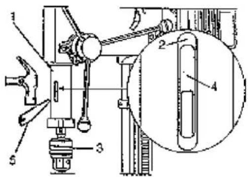
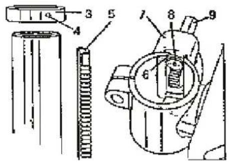
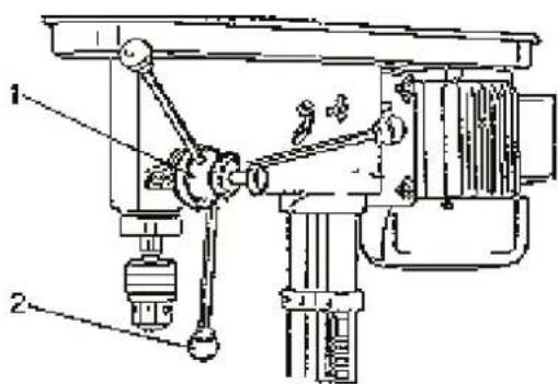
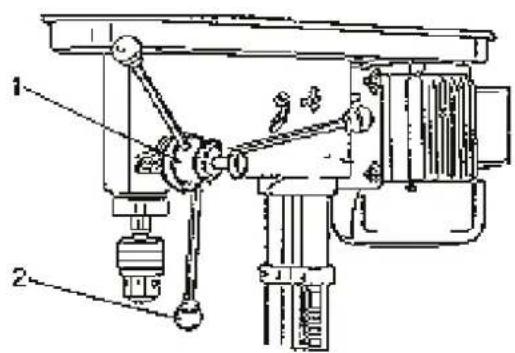
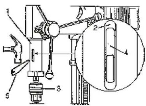
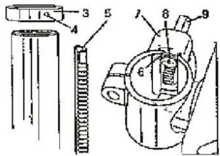
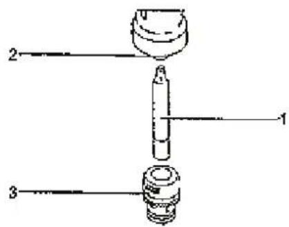
Removal of Chuck (Fig. 13)
- If the chuck is to be lowered completely. unloose the quill sleeve (1). Use the advancement hand lever to do it. There big oval holes on both sides of the quill sleeve (2).
- Rotate the chuck (3) until the quill hole (4) and the sleeve hole are in alignment
- Insert the wedge (5) and knock it slightly with a hammer.
- Both the shaft and chuck will fall down from the quill.
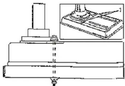
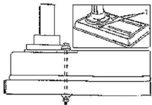
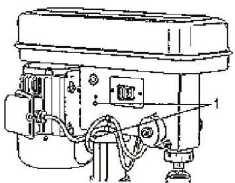
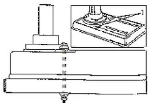
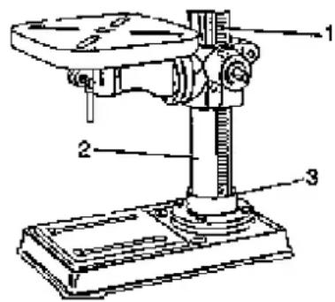
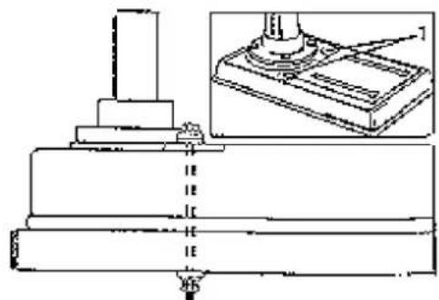
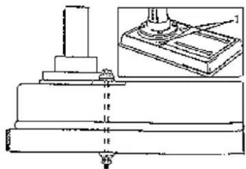
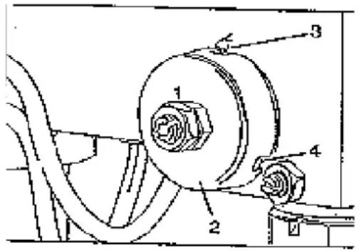
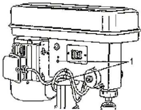
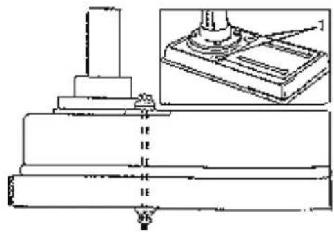
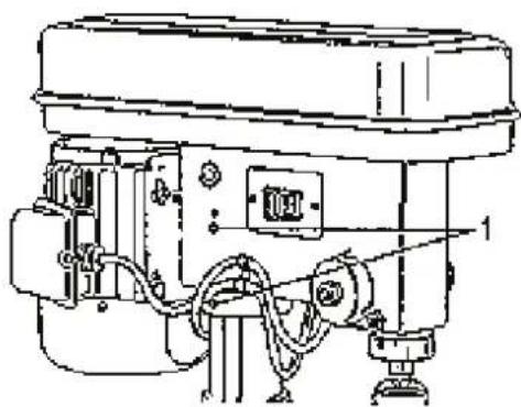
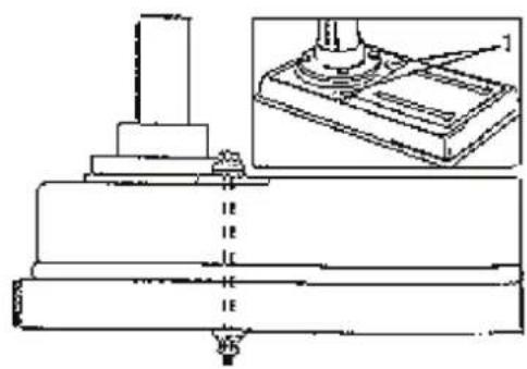
Drill Assembling (Fig. 14)
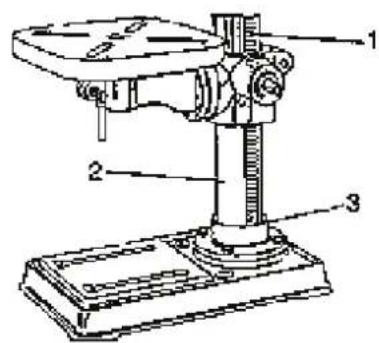
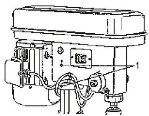
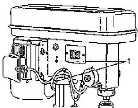
- Mount your drill by means of two holes (1) in the base plate to a stand or a bench. using premium assembling material. That should prevent any rollover. slip or shift of the machine in operation. IMPORTANT NOTICE: When the stand or the bench begin to move while the drill is working. fix it safely to the floor.
text_image
knob washer screwFig. 11
text_image
2 1 3Fig. 12
text_image
Technical diagram of a mechanical assembly with numbered components and a magnified inset showing a component labeled 2.Fig. 13
text_image
Technical diagram showing a mechanical assembly with labeled components and an inset view of a component.Fig. 14
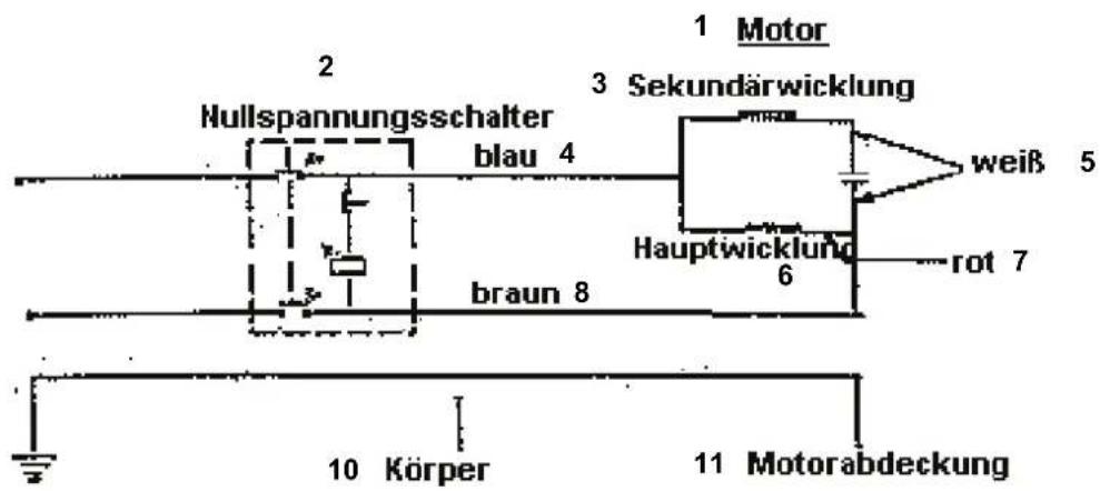
8. Adjustment

- Motor 7. Red
- Zero voltage switch 8. Brown
- Secondary winding 9. Yellow green
- Blue 10. Body
- White 11. Motor housing
- Main winding
Quill Speed Change (Fig. 16)
- Disconnect the drill column from the voltage source.
- Open the pulley housing
- Release the slide rails knob (1).
- Tilt the motor forward to release tension on both the belts.
- Re-set the belts in the pulleys corresponding to the required quill speed (2).
- Stretch the belts and tilt the motor to the machine rear side.
- Tighten the slide rails knob (1).
- Close the pulley housing.
- Turn the machine on to check if the belts tension is correct.
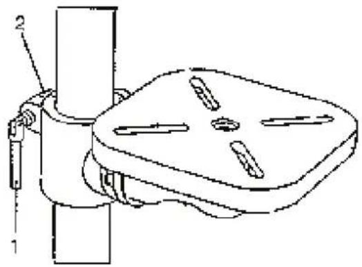
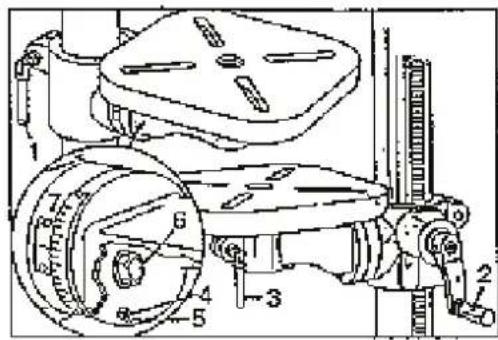
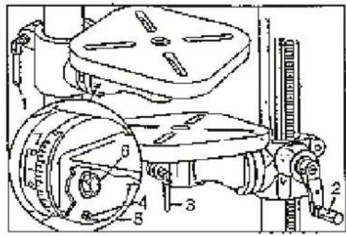
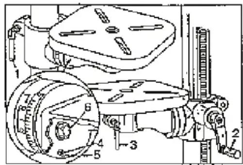
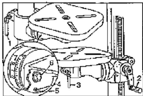
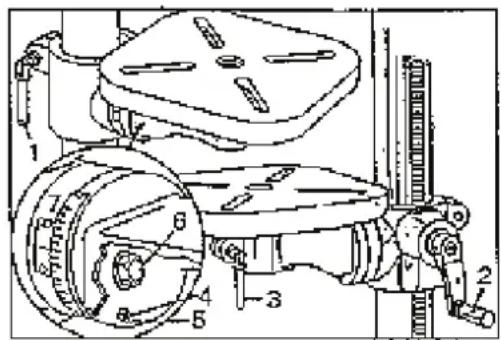
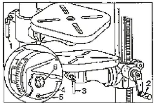
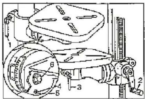
Bench Adjustment (Fig.17)
- The bench may be lifted or lowered to a required position by releasing the column lock (1) and turning the crank (2). Before drilling is started, the column lock has to be re-tightened.
- If you want to turn the bench around the column. release the column lock (1) and then re-tighten it again.
- If you want to turn the bench only. release the bench lock (3) and turn the bench to the required position. Re-tighten the lock again.
- If you want to see the bench at an angle of 0^ - 45^ (to the right/to the left). Remove the pin (4) and the nut (5). If the pin is stuck, turn the nut (5) clockwise until the pin slips out. Release the bench lock screw (6). incline the table at the required angle and tighten the screw (6). If you want the bench put back in the position of 0^ . insert the pin again (4) and tighten the screw (6). Transversal setting scale spacing is on the bench attachment device (7).
text_image
Technical diagram of a mechanical device with labeled components and directional arrows indicating motion or flow.Fig. 16
Fig. 17
text_image
Technical diagram of a mechanical assembly with numbered components and labeled partsDrilling Depth (Fig. 18)
When drilling blind holes. take the drill quill down with the machine off and set the bit to the piece to be drilled. Now, loose the down stop and zero (set to "0") the scale. Clamp the stop again and read the current down depth on the scale.
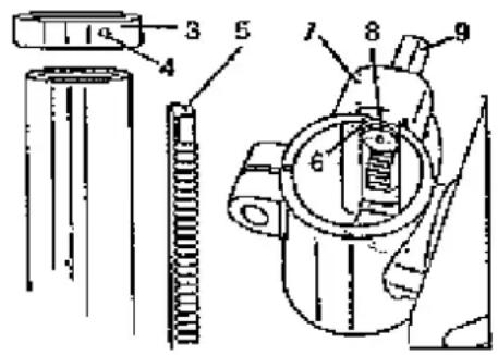
Quill Return Spring (Fig. 19)
An automatic return mechanism is fitted on the quill. The main components are a spring and a grooved chromium-plated housing. The spring is factory-set as appropriate and the setting should not be changed
text_image
Technical diagram of a mechanical assembly with labeled components 1 and 2Fig. 18
text_image
Technical diagram of a mechanical assembly with numbered componentsFig. 19
IMPORTANT NOTICE: the nut should not be tightened too firmly. If the nut tightening is too firm, quill movement is made more difficult.
9. Operation
Drilling Speeds
Factors influencing the drilling sped: type of material. drilled hole size. type of bit. required quality of cut. Remember that the smaller the bit is the larger is the required speed. When drilling soft materials. higher speed is required than that for the hard materials (see the table of drilling specifications).
Metal Drilling
Metal pieces need to be clamped safely. some of our vices are recommended. Never hold the piece just with hands. The bit cutting edges may catch the piece and cause a serious injury to you. The bit will get broken when a metal object strikes against the column.
The piece to be drilled should be firmly clamped. Any tilting, twisting and shifting will result in a rough drilled hole and the risk of breaking the bit will increase as well. If the metal object is flat, underlay it with a piece of wood to prevent spinning. If the shape is irregular and its area cannot lie on the bench entirely, it should be fixed.
Wood Drilling
It is possible to use the metal working bits for wood working as well. however, wood drilling bits should be preferred. Do not use twist drills. those rotate so fast that they will lift the drilled piece from the bench and will spin it around. To drill the material through, the bench has to be aligned for the bit to get in the centre hole. When the bit starts cutting wood, the advance should add gradually to prevent the material from shattering. Put a piece of waste wood under the worked material as a pad. It will help to reduce the shattering qualities and protect the drill bit tip.
Advancement
Apply sufficient force on the advancement hand lever to press it down. interrupt the advancement now and then to keep the chips short or to direct the sawdust from the hole being drilled. Too fast advancement could result in the motor stopping. belt slipping, damaging the piece being drilled or breaking the bit. Too slow advancement could heat the drilling bit and the piece being drilled could get burnt.
10. Maintenance
WARNING: SWITCH OVER TO "OFF" POSITION AND UNPLUG THE MACHINE BEFORE MAINTENANCE OR LUBRICATION OF THE MACHINE FOR YOU TO BE SAFE.
Blow off or suck off any sawdust and chips gather on the motor. pulley housing. bench and the drilled piece surface.
Wipe the gloss surface with an oiled cloth.
Apply a layer of pasty wax on the column and the bench to keep the surfaces clean with any spots of rust.
The ball bearings in the pinion and v-belt pulley assembly are lubricated for life and sealed permanently. Pull the pinion down and lubricate with oil on a three-month basis.
If the bench clamping devices and locking knobs run heavily. Lubricate them.
CAUTION: Any routine and scheduled maintenance of the drill should be done by an authorised servicing technician.
11. Drilling Specifications Table
12. Machine Exploded View Drawing
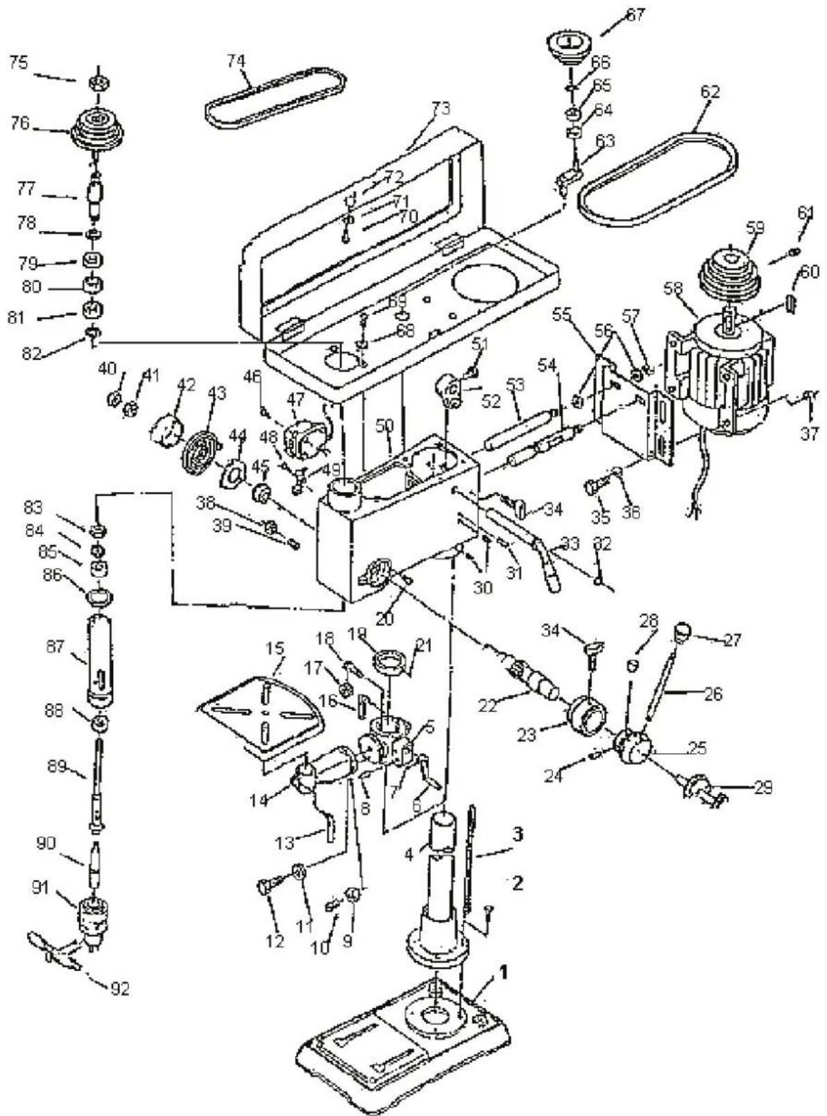
text_image
Exploded view diagram of a mechanical assembly with numbered parts and exploded view indicators- List of Spare Parts for GTB 13
| Part No. | Description | Quantity | Note | Part No. | Description | Quantity | Note |
| 1 | Base plate 1 | 47 | Switch 1 | ||||
| 2 | Screw/Bolt 4 (M10x40) | M10x25 | 48 | Screw 1 | M | 5x10 | |
| 3 | Rack 1 | 49 | Screw | clamp 1 | |||
| 4 | Column 1 | 50 | Body | 1 | |||
| 5 | Bench lock 1 | 51 | Screw/Bolt 1 | M8x16 | |||
| 6 | Hand grip | 1 | 52 | Point operating level | 1 | ||
| 7 | Headless set screw | 1 | M6x10 | 53 | Sliding bar / shifting device | 1 | |
| 8 | Shaft | 1 | 54 | Sliding bar / shifting device | 1 | ||
| 9 | Nut | 1 | M6 | 55 | Motor base plate | 1 | |
| 10 | Pin | 1 | 56 | Washer | 2 | 12 | |
| 11 | Washer | 1 | Split washer | 2 | 12 | ||
| 12 | Screw/Bolt | 1 | M12x35 | 57 | Nut | 2 | M 12 |
| 13 | Bench screw | 1 | 58 | Motor | 1 | ||
| 14 | Bench bracket | 1 | 59 | Motor pulley | 1 | ||
| 15 | Bench | 1 | 60 | Plain key | 1 | ||
| 16 | Clamping screw | 1 | 61 | Headless set screw | 1 | M10x12 | |
| 17 | Gear wheel | 1 | 62 | v-belt | 1 | A-630 | |
| 18 | Worm | 1 | 63 | Centring shaft | 1 | ||
| 19 | Rack ring | 1 | 64 | Ball bearing | 1 | 60202 | |
| 20 | Stop pin | 1 | 65 | Ball bearing | 1 | 60202 | |
| 21 | Headless set screw | 1 | M6x10 | ||||
| 22 | Advancement hand lever | 1 | 67 | Centring pulley | 1 | ||
| 23 | Scale ring | 1 | 68 | Washer | 4 | 6 | |
| 24 | Cylindrical pin | 1 | 5x40 | 69 | Screw | 1 | M6x8 |
| 25 | Hand grip body | 1 | 70 | Screw | 1 | M5x10 | |
| 26 | Hand grip | 3 | |||||
| 27 | Knob | 3 | |||||
| 28 | Wrench | 1 | 73 | Pulley housing | 1 | ||
| 29 | Shifting device screw | 1 | 74 | v-belt | 1 | A-610 | |
| 30 | Headless set screw | 2 | M10x12 | 75 | Pulley Nut | 1 | |
| 31 | Cylindrical pin | 2 | 6x25 | 76 | Quill pulley | 1 | |
| 32 | Shaft buckling rings | 1 | 15 | 77 | Shifting pulley | 1 | |
| 33 | Point operating lever bar | 1 | |||||
| 34 | Shifting device screw | 2 | 79 | Ball bearing | 1 | 60205 | |
| 35 | Screw/Bolt | 4 | M8x25 | 80 | Spacer | 1 | |
| 36 | Washer | 4 | 8 | 81 | Ball bearing | 1 | 60205 |
| 37 | Nut | 4 | M8 | ||||
| 38 | Nut | 1 | M10 | 83 | Round Nut | 1 | M17x1 |
| 39 | Screws - special kit | 1 | 84 | Round nut coupling washer | 1 | ||
| 40 | Nut | 1 | M12x1.5 | 85 | Ball bearing | 1 | 60203 |
| 41 | Nut | 1 | M12x1.5 | 86 | Rubber washer | 1 | |
| 42 | Flexible cup | 1 | 87 | Quill lug | 1 | ||
| 43 | Twist spring | 1 | 88 | Ball bearing | 1 | 80205(80206) | |
| 44 | Spring housing | 1 | 89 | Quill | 1 | ||
| 45 | Spring guide | 1 | 90 | Shaft | 1 | ||
| 46 | Screw | 2 | M4x12 | 91 | Chuck | 1 | |
14. List of Spare Parts GTB 16. GTB 20. GSB 20. GSB 25 R+L. GSB 32 R+L
| Part No. | Description | Quantity | Note | Part No. | Description | Quantity | Note |
| 1 | Base plate 1 47 Switch | 1 | |||||
| 2 | Screw/bolt 4 M12x30 48 | Screw 1 | M 5x10 | ||||
| 3 | Rack 1 | 49 Screw | clamp | 1 | |||
| 4 | Column | 1 | 50 | Body | 1 | ||
| 5 | Bench lock | 1 | 51 | Screw/bolt | 1 | M8x16 | |
| 6 | Hand grip 1 | 52 Point operating lever | 1 | ||||
| 7 | Locking bolt | 1 | M6x10 | 53 | Sliding bar/shifting device | 1 | |
| 8 | Shaft 1 | 54 Sliding bar/shifting device | 1 | ||||
| 9 | Nut | 1 | M6 | 55 | Motor base plate | 1 | |
| 10 | Pin | 1 56 Washer | 2 12 | ||||
| 11 | Washer | 1 | Split washer | 2 | 12 | ||
| 12 | Screw/bolt | 1 | M20x40 | 57 | Nut | 2 | M 12 |
| 13 | Bench screw | 1 58 Motor | 1 | ||||
| 14 | Bench clamping arm 1 | 59 Motor pulley | 1 | ||||
| 15 | Bench | 1 | |||||
| 16 | Clamping screw | 1 | 61 | Locking bolt | 1 | M10x12 | |
| 17 | Gear wheel | 1 | 62 | v-belt | 1 | A-630 | |
| 18 | Worm | 1 | 63 | Central shaft | 1 | ||
| 19 | Rack ring | 1 | 64 | Ball bearing | 1 | 60202 | |
| 20 | Stopper pin | 1 | 65 | Ball bearing | 1 | 60202 | |
| 21 | Locking bolt | 1 | M6x10 | ||||
| 22 | Advance hand lever 1 | 67 Central pulley | 1 | ||||
| 23 | Scale ring | 1 | 68 | Washer | 4 | 6 | |
| 24 | Cylindrical pin | 1 | 5x40 | 69 | Screw | 1 | M6x8 |
| 25 | Hand grip body | 1 70 Screw 1 M5x10 | |||||
| 26 | Hand grip | 3 71 Washer | 1 5 | ||||
| 27 | Knob | 3 | 72 | Knob | 1 | ||
| 28 | Wrench | 1 | 73 | Pulley housing | 1 | ||
| 29 | Shifting device screw | 1 | 74 | v-belt | 1 | A-610 | |
| 30 | Locking bolt | 2 | M10x12 | 75 | Pulley nut | 1 | |
| 31 | Cylindrical pin | 2 | 6x25 | 76 | Quill pulley | 1 | |
| 32 | Shaft bucking ring I | 1 | 15 | 77 | Shifting pulley | 1 | |
| 33 | Point operating lever bar | 1 | |||||
| 34 | Shifting device screw | 2 | 79 | Ball bearing | 1 | 60207 | |
| 35 | Screw/bolt | 4 | M8x25 | 80 | Spacer | 1 | |
| 36 | Washer | 4 | 8 | 81 | Ball bearing | 1 | 60207 |
| 37 | Nut | 4 | M8 | ||||
| 38 | Nut | 1 | M10 | 83 | Round nut | 1 | M30x1.5 |
| 39 | Special kit of screws | 1 | 84 | Round nut coupling washer | 1 | ||
| 40 | Nut | 1 | M12x1.5 | 85 | Ball bearing | 1 | 60206 |
| 41 | Nut | 1 | M12x1.5 | 86 | Rubber washer | 1 | |
| 42 | Flexible cup | 1 | 87 | Quill lug | 1 | ||
| 43 | Twist spring | 1 | 88 | Ball bearing | 1 | 60207. 8706 | |
| 44 | Spring cover | 1 | 89 | Quill | 1 | ||
| 45 | Spring guide | 1 | 90 | Shaft | 1 | ||
| 46 | Screw | 2 | M4x12 | 91 | Chuck | 1 | |
15. Pack Sheet GTB 13
| No. | Description Size Quantity | ||
| 1 Head assembly 1 | |||
| 2 | Bench assembly | 1 | |
| 3 | Base plate 1 | ||
| 4 | Column assembly | 1 | |
| 5 | Chuck 13mm | 1 | |
| 6 Wedge-shaped slide valve 1 | |||
| 7 Internal hexagon wrench 3mm 1 | |||
| 8 Internal hexagon wrench 5mm 1 | |||
| 9 Screw/bolt M10x25 or M10x40 | 4 | ||
| 10 | Operating instructions (manual) | 1 | |
16. Pack Sheet GTB 16. GTB 20. GSB 20. GSB 25 R+L. GSB 32 R+L
| No. | Description Size Quantity | ||
| 1 Head assembly 1 | |||
| 2 | Bench assembly | 1 | |
| 3 | Base plate 1 | ||
| 4 | Column assembly | 1 | |
| 5 | Chuck 16mm | 1 | |
| 6 Wedge-shaped slide valve 1 | |||
| 7 Internal hexagon wrench 3mm 1 | |||
| 8 Internal hexagon wrench 5mm 1 | |||
| 9 | Screw/bolt M10x25 orM10x40 | 4 | |
| 10 | Operating instructions (manual) | 1 | |
EC Declaration of Conformity
Güde GmbH & Co. KG
We herewith declare, Birkichstrasse 6, 74549 Wolpertshausen, Germany
that the following appliance complies with the essential safety and health requirements stipulated by the EC Directives both by its concept and design and the types we have put on the market.
Any unauthorised alteration of the machine shall make this declaration null and void.
- Bench and Column Drills
Machine Description:
- GTB 13 55120;
Article-No.: - GTB 16/5 55190; GTB 16/12 R+L 55192
- GTB 20/12 55193; GBT 20/12 R+L 55194
- GSB 20/12 55195; GSB 20/12 R+L 55197
Applicable EC Directives: - 2004/108/EC
- 2006/42/EG
Applicable harmonized - EN 55014-1:2006
Standards: - EN 55014-2:1997/+A1:2002
- EN 61000-3-2:2006
- EN 61000-3-3:1995/+A1:2001/+A2:2005
- EN 61029-1:2009
Date/Authorized Signature: 30.09.2011,
Title of Signatory: Arnold, executive officer
Table des matières
text_image
Technical diagram of a mechanical assembly with numbered parts, likely an engine or drill press system.8. Montage
Parties - Figuration 1
text_image
Technical diagram of a mechanical assembly with numbered components and labeled partsnatural_image
Line drawings of four different hand tools: wrench, hammer, screwdriver, and flat (no text or symbols)Fig. 2
natural_image
Technical line drawing of a mechanical device with a central cylindrical component and three protruding pins (no text or symbols)Fig. 3
text_image
Technical diagram of a mechanical assembly with numbered components and cross-sectional viewsFig. 4
text_image
Technical diagram of a drill press with numbered parts labeled 1, 2, and 3Fig. 5
text_image
5 4 1Fig. 6
text_image
Technical diagram of a mechanical assembly with labeled parts 1 and 2Fig. 7
text_image
Technical diagram of a mechanical device with labeled parts 1 and 2Fig. 8
natural_image
Technical line drawing of an industrial machine with control panel and wiring (no text or symbols)Fig. 9
text_image
Technical diagram of a mechanical assembly with labeled parts 1 and 2Fig. 10
text_image
knob washer screwFig. 11
text_image
2 1 3Fig. 12
text_image
Technical diagram of a mechanical assembly with numbered components and a magnified inset viewAbb. 13
natural_image
Technical line drawing of a mechanical assembly with a base and top component, showing no text or symbols.Abb. 14
9. Ajustage
text_image
Technical diagram of a mechanical device with labeled components and directional arrows indicating motion or flow.Fig. 16
Fig. 17
text_image
Technical diagram of a mechanical assembly with numbered components and labeled partstext_image
Exploded view diagram of a mechanical device with numbered parts and exploded view, likely for assembly or maintenance purposes.EC Declaration of Conformity
that the following Appliance complies with the appropriate basic safety and health requirements of the EC Directive based on its design and type, as brought into circulation by us.
In a case of alternation of the machine, not agreed upon by us, this declaration will lose ist validity.
Machine Description:
Directives CE applicables: - 2004/108/EC
Applicable EC Directives: - 2006/42/EG
Date/Authorized Signature:
text_image
Technical diagram of a mechanical assembly with numbered parts for identification and assembly reference.8. Montáž
Montáž a čištění
text_image
Technical diagram of a mechanical device with numbered parts, including a drill press and various tools.Obr. 1
natural_image
Line drawings of four different wrenches and screwdrivers (no text or symbols)Obr. 2
natural_image
Technical line drawing of a mechanical component with mounting flanges and a central cylindrical housing (no text or symbols)O b r . 3
text_image
Technical diagram of a mechanical assembly with numbered components and cross-sectional views0
text_image
Technical diagram of a mechanical device with numbered parts labeled 1, 2, and 3.O b r . 5
text_image
5 4 1o b
natural_image
Technical line drawing of a mechanical assembly with labeled parts (no text or symbols present)O b r . 7

natural_image
Technical line drawing of a mechanical clamp or fixture with a cylindrical base and four circular components (no text or symbols)0
natural_image
Technical line drawing of an industrial machine with control panel and wiring (no text or symbols)O b r . 9

text_image
Technical diagram of a mechanical assembly with labeled parts 1 and 20
text_image
Technical diagram of a mechanical device with labeled components and directional arrows indicating motion or flow.Obr. 16
Obr. 17
text_image
Technical diagram of a mechanical assembly with numbered components and labeled partstext_image
Exploded view diagram of a mechanical assembly with numbered parts and exploded view indicatorsEC Declaration of Conformity
Tímto prohlašujeme my, Güde GmbH & Co. KG
We herewith declare, Birkichstrasse 6, 74549 Wolpertshausen, Germany
that the following Appliance complies with the appropriate basic safety and health requirements of the EC Directive based on its design and type, as brought into circulation by us.
In a case of alternation of the machine, not agreed upon by us, this declaration will lose ist validity.
Označení prístrojů:
Machine Description:
Applicable EC Directives: - 2006/42/EG
Date/Authorized Signature:
Údaje o podepsaném: pan Arnold, jednatel
Title of Signatory:

Obsah
ČLÁNOKSTRANA
text_image
Technical diagram of a mechanical assembly with numbered parts for identification and assembly reference.8. Montáž
Montáž a čistenie
text_image
Exploded view diagram of a mechanical device with numbered parts and labeled componentsObr. 1
natural_image
Line drawings of four different wrenches and screwdrivers (no text or labels)Obr. 2
natural_image
Technical line drawing of a mechanical device with mounting base and cylindrical components (no text or symbols)O b r . 3

text_image
Technical diagram of a mechanical assembly with numbered components and cross-sectional views0

text_image
Technical diagram of a mechanical device with numbered parts labeled 1, 2, and 3.O b r . 5

text_image
1 2 3 4 5o b
natural_image
Technical line drawing of a mechanical assembly with labeled parts (no text or symbols present)O b r . 7
natural_image
Technical line drawing of a mechanical clamp or fixture with labeled parts (no text or symbols present)0

natural_image
Technical line drawing of an industrial machine with control panel and wiring (no text or symbols)O b r . 9
text_image
Technical diagram of a mechanical assembly with labeled components 1 and 20
text_image
Technical diagram of a mechanical device with labeled components and directional arrows indicating motion or flow.Obr. 16
Obr. 17
text_image
Technical diagram of a mechanical assembly with numbered components and labeled partsHíbka vrtania (obr. 18)
text_image
Technical diagram of a mechanical assembly with labeled components 1 and 2Obr. 18
text_image
Technical diagram of a mechanical assembly with numbered componentsObr. 19
text_image
Exploded view diagram of a mechanical assembly with numbered parts and exploded view indicatorsEC Declaration of Conformity
Týmto vyhlasujeme my, Güde GmbH & Co. KG
We herewith declare, Birkichstrasse 6, 74549 Wolpertshausen, Germany
that the following Appliance complies with the appropriate basic safety and health requirements of the EC Directive based on its design and type, as brought into circulation by us.
In a case of alternation of the machine, not agreed upon by us, this declaration will lose ist validity.
Machine Description:
Applicable EC Directives: - 2006/42/EG
Date/Authorized Signature:
Údaje o podpísanom: pán Arnold, konatel'
Title of Signatory:
Inhoud
HOOFDSTUK PAGINA
text_image
Technical diagram of a mechanical assembly with numbered parts, likely an engine or drill press system.8. Montage
Montage en schoonmaken
text_image
Technical diagram of a mechanical device with numbered parts for identification and assembly reference.Afb. 1
natural_image
Line drawings of four different tools: wrench, hammer, screwdriver, and flat plate (no text or symbols)Afb. 2
natural_image
Technical line drawing of a mechanical device with a central cylindrical component and three protruding pins (no text or symbols)A f b . 3
text_image
Technical diagram of a mechanical assembly with numbered components and cross-sectional viewsA
text_image
Technical diagram of a mechanical device with numbered parts labeled 1, 2, and 3.A f b . 5
text_image
5 4 1Afb. 6
Boormachinekop en kolom
text_image
Technical diagram of a mechanical assembly with labeled parts 1 and 2A
f
b
7
text_image
Technical diagram of a mechanical clamp or bracket assembly with labeled parts 1 and 2A
natural_image
Technical line drawing of an industrial machine with control panel and wiring (no text or symbols)A
f
b
9

text_image
Technical diagram of a mechanical assembly with labeled parts 1 and 2A
text_image
knob washer screwAfb. 11
text_image
2 1 3Afb. 12
text_image
Technical diagram of a mechanical assembly with numbered components and a magnified inset showing a component labeled 4.Afb. 13
text_image
Technical diagram showing a mechanical assembly with labeled parts and an inset view of a component.Afb. 14
9. Instellingen
text_image
Technical diagram of a mechanical device with labeled components and directional arrows indicating motion or flow.Afb. 16
Afb. 17
text_image
Technical diagram of a mechanical assembly with numbered components and labeled partstext_image
Technical diagram of a mechanical assembly with numbered components labeled 1 to 4text_image
Exploded view diagram of a mechanical assembly with numbered parts and exploded view indicatorsEC Declaration of Conformity
Hiermee verklaren wij, Güde GmbH & Co. KG
We herewith declare, Birkichstrasse 6, 74549 Wolpertshausen, Germany
that the following Appliance complies with the appropriate basic safety and health requirements of the EC Directive based on its design and type, as brought into circulation by us.
In a case of alternation of the machine, not agreed upon by us, this declaration will lose its validity.
Machine Description:
Applicable EC Directives: - 2006/42/EG
Date/Authorized Signature:
text_image
Technical diagram of a mechanical assembly with numbered parts, including drill press, baseplate, and bearing components.8. Montaggio
Montaggio e pulizia
text_image
Technical diagram of a mechanical device with numbered components and labeled partsObr. 1
Fig. 1
natural_image
Line drawings of four different hand tools: wrench, hammer, screwdriver, and flat (no text or symbols)Fig. 2
natural_image
Technical line drawing of a mechanical device with mounting base and cylindrical component (no text or symbols)Fig. 3
text_image
Technical diagram of a mechanical assembly with numbered components and cross-sectional viewsFig. 4
text_image
Technical diagram of a mechanical device with numbered parts labeled 1, 2, and 3.Fig. 5
text_image
Technical diagram of a mechanical assembly with labeled parts 1, 4, and 5F i g. 6
text_image
Technical diagram of a mechanical assembly with labeled parts 1 and 2Fig. 7
text_image
Technical diagram of a mechanical clamp or fixture with labeled parts 1 and 2Fig. 8
natural_image
Technical line drawing of an industrial machine with no visible text or symbolsFig. 9
text_image
Technical diagram of a mechanical assembly with labeled parts 1 and 2Fig. 10
text_image
knob washer screwFig. 11
text_image
2 1 3Fig. 12
text_image
Technical diagram of a mechanical assembly with numbered components and an inset view showing a cylindrical component.Fig. 13
text_image
Technical diagram showing a mechanical assembly with labeled components and an inset view of a component.Fig. 14
text_image
Technical diagram of a mechanical device with labeled components and numbered partsFig. 16
Fig. 17
text_image
Technical diagram of a mechanical assembly with numbered components for identificationtext_image
Technical diagram of a mechanical assembly with labeled components 1 and 2Fig. 18
text_image
Technical diagram of a mechanical assembly with numbered componentsFig. 19
text_image
Exploded view diagram of a mechanical assembly with numbered parts and exploded view indicatorsEC Declaration of Conformity
that the following Appliance complies with the appropriate basic safety and health requirements of the EC Directive based on its design and type, as brought into circulation by us.
In a case of alternation of the machine, not agreed upon by us, this declaration will lose its validity.
Machine Description:
Applicable EC directives:
- 2004/108/EC
- 2006/42/EG
Standard normativi in merito - EN 55014-1:2006
applicati: - EN 55014-2:1997/+A1:2002
Applicable harmonized - EN 61000-3-2:2006
Standards: - EN 61000-3-3:1995/+A1:2001/+A2:2005
- EN 61029-1:2009
Date/Authorized Signature:
text_image
Technical diagram of a mechanical assembly with numbered parts and exploded views, likely for engineering or manufacturing documentation.Montaža
Montaža in čiščenje
text_image
Technical diagram of a mechanical device with numbered parts, including a drill press and various tools.natural_image
Line drawings of four different tools: wrench, screwdriver, hammer, and flatener (no text or symbols)Slika 2
Orodja potrebna za montažo:
Nastavljiv ključ za vijake Izvijač*
Kladivo in košček lesa
natural_image
Technical line drawing of a mechanical component with mounting base and cylindrical features (no text or symbols)Slika
3
text_image
Technical diagram of a mechanical assembly with numbered components for identificationSlika
4
text_image
Technical diagram of a mechanical device with numbered parts labeled 1, 2, and 3.Slika
5
text_image
1 2 3 4 5Slika
6
Montaža glave vrtalnika na steber
text_image
Technical diagram of a mechanical assembly with labeled parts 1 and 2Slika
7
text_image
Technical diagram of a mechanical device with labeled parts 1 and 2Slika
8
natural_image
Technical line drawing of an industrial machine with control panel and wiring (no text or symbols)Slika
9
text_image
Technical diagram of a mechanical assembly with labeled parts 1 and 2Slika
10
text_image
Technical diagram of a mechanical device with labeled components and directional arrows indicating motion or flow.Slika
1
6
text_image
Technical diagram of a mechanical assembly with numbered components for identificationSlika 17
Globina vrtanja (slika 18)
text_image
Exploded view diagram of a mechanical assembly with numbered parts and exploded view indicatorsEC Declaration of Conformity
Ezennel kijelentjük Güde GmbH & Co. KG
We herewith declare, Birkichstraße 6, 74549 Wolpertshausen, Germany
that the following Appliance complies with the appropriate basic safety and health requirements of the EC Directive based on its design and type, as brought into circulation by us.
In a case of alternation of the machine, not agreed upon by us, this declaration will lose its validity.
Machine Description:
Applicable EC Directives: - 2006/42/EG
Date/Authorized Signature:
text_image
Technical diagram of an electrical switch or relay with numbered components labeled 1 through 8
text_image
13 19 21 26 29 31
text_image
Technical diagram of a drill press with numbered parts for identification8. Montaža
Montaža i čišćenje
Bušilicu i sve njezine dijelove oprezno raspakirajte te usporedite s dolje navedenim popisom. Dok ne bude montaža sasvim završena, sačuvajte karton i omote.
Da bude bušilica zaštićena od vlage, imaju obrađene površine zaštitni sloj. Ovaj sloj skinite mekom krpicom navlaženom kerozinom ili sredstvom WD-40. ZA OČIŠĆENJE NIKAKO ne koristite aceton, benzin, ni razrjeđivač.
Dijelovi slika 1
1 - Konstrukcijski komplet motora 10 - Dršci / poluga pomicanja
2 - Stup 11 - Poluga za podešavanje stupa
3 - Upute za korištenje (priručnik) 12 - Poklopac
4 - Čunjasti trn 13 - 2 šesterokutna ključa & klin
5 - Ručka stolu
6 - Vijci / svornjaci
7 - Glava za svrdla i ključ za stezanje glave
8 - Stol
9 - Osnovna ploča

text_image
Osnovna ploča 1 2 3 4 5 6 7 8 9 10 11 12 13Slika 1
Upozorenje: Ako neki dio nedostaje ili je oštećen, ne uključujte bušilicu u izvor električne struje sve dok ne zamijenite takav dio i ne dovršite montažu.

natural_image
Line drawings of four different wrenches and tools (no text or labels)Slika 2
Alat potreban za montažu:
- Podesiv ključ za vijke
- Odvijač
- Čekić i komad drva
natural_image
Technical line drawing of a mechanical device with labeled components (Slika, 3), no readable text or symbols beyond labels
text_image
3 4 5 7 8 9 6 Slika
text_image
1 2 3 Slika 5
text_image
Slika 6Montaža glave bušilice na stup
- Glavu bušilice oprezno podignite i uvedite u položaj iznad stupa. Ako je manipulacija s glavom za Vas preteška, radite uz pomoć druge osobe.
- Stup stane u montažni otvor bušilice. Uvjerite se da je montažni otvor dobro postavljen na stup. Glavu bušilice postavite u istu os sa stolom i osnovnom pločom te uz pomoć šesterokutnog ključa zategnite dva zatezna vijka (slika 9).
text_image
Technical diagram of a mechanical assembly with labeled parts 1 and 2Slika 7
natural_image
Technical line drawing of a mechanical clamp or fixture with labeled parts (no text or symbols present)Slika 8

natural_image
Technical line drawing of an industrial machine with control panel and wiring (no text or symbols)Slika 9

text_image
Technical diagram of a mechanical assembly with labeled parts 1 and 2Slika 10
Montaža poklopca remenice (slika 11)
- Kroz otvor u poklopcu remenica protaknite podlošku i vijak.
- Dugme navijte na vijak i zategnite ga.
text_image
Technical diagram of a mechanical device with labeled components and directional arrows indicating motion or flow.
text_image
Technical diagram of a mechanical assembly with numbered components and directional arrows indicating motion or flow.Slika 16
Slika 17
Dubina bušenja (slika 18)
Za bušenje slijepih otvora vodite mirujuće vreteno bušilice prema dolje da svrdlo dotakne bušeni materijal. Sad popustite vijak za ugađanje dubine te na ljestvici namjestite na "0". Vijak za ugađanje opet zategnite pa na ljestvici pročitajte aktualnu dubinu bušenja.
Povratna opruga vretena (slika 19)
text_image
Exploded view diagram of a mechanical assembly with numbered parts and exploded view indicatorsEC Declaration of Conformity
that the following Appliance complies with the appropriate basic safety and health requirements of the EC Directive based on its design and type, as brought into circulation by us.
V primeru spremembe naprave, o kateri se niste posvetovali z nami, ta izjava izgubi svojo veljavnost.
In a case of alternation of the machine, not agreed upon by us, this declaration will lose its validity.
Machine Description:
Številka izdelka: - GTB 13 55120;
Article-No.: - GTB 16/5 55190; GTB 16/12 R+L 55192
- GTB 20/12 55193; GBT 20/12 R+L 55194
- GSB 20/12 55195; GSB 20/12 R+L 55197
Uporabne smernice EU: - 2004/108/EC
Applicable EC Directives: - 2006/42/EG
Uporabljene norme - EN 55014-1:2006
skladnosti - EN 55014-2:1997/+A1:2001
Applicable harmonized - EN 61000-3-2:2006
Standards: - EN 61000-3-3:1995/+A1:2001/+A2:2005
- EN 61029-1:2009

Datum/podpis proizvajalca: 30.09.2011
Date/Authorized Signaure:
Podatki o podpisniku: gospod Arnold, direktor
Title of Sinatory:
Sadržaj
ČLANAK STRANA
text_image
Technical diagram of an electrical switch or relay with numbered components labeled 1 through 8
text_image
13 19 21 26 29 31
text_image
Technical diagram of a drill press with numbered parts for identification8. Montaža
Montaža i čišćenje
Bušilicu i sve njezine dijelove oprezno raspakirajte te usporedite s dolje navedenim popisom. Dok ne bude montaža sasvim završena, sačuvajte karton i omote.
Da bude bušilica zaštićena od vlage, imaju obrađene površine zaštitni sloj. Ovaj sloj skinite mekom krpicom navlaženom kerozinom ili sredstvom WD-40. ZA OČIŠĆENJE NIKAKO ne koristite aceton, benzin, ni razrjeđivač.
Dijelovi slika 1
1 - Konstrukcijski komplet motora 10 - Dršci / poluga pomicanja
2 - Stup 11 - Poluga za podešavanje stupa
3 - Upute za korištenje (priručnik) 12 - Poklopac
4 - Čunjasti trn 13 - 2 šesterokutna ključa & klin
5 - Ručka stolu
6 - Vijci / svornjaci
7 - Glava za svrdla i ključ za stezanje glave
8 - Stol
9 - Osnovna ploča
text_image
Osnovna ploča 1 2 3 4 5 6 7 8 9 10 11 12 13Slika 1
Upozorenje: Ako neki dio nedostaje ili je oštećen, ne uključujte bušilicu u izvor električne struje sve dok ne zamijenite takav dio i ne dovršite montažu.
natural_image
Line drawings of four different wrenches and tools (no text or labels)Slika 2
Alat potreban za montažu:
- Podesiv ključ za vijke
- Odvijač
- Čekić i komad drva
natural_image
Technical line drawing of a mechanical device with labeled components (Slika, 3), no readable text or symbols beyond labels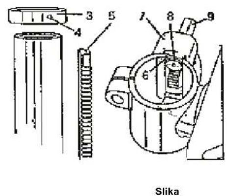
text_image
3 4 5 7 8 9 6 Slika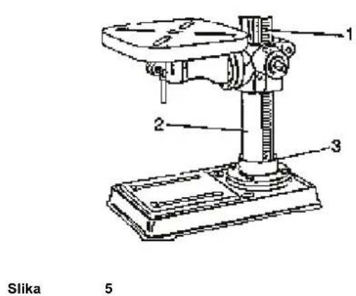
text_image
1 2 3 Slika 5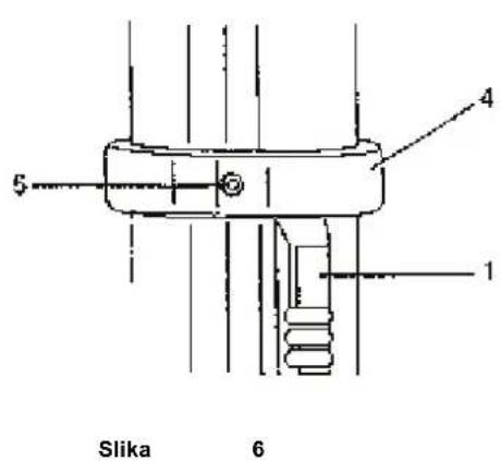
text_image
Slika 6Montaža glave bušilice na stup
- Glavu bušilice oprezno podignite i uvedite u položaj iznad stupa. Ako je manipulacija s glavom za Vas preteška, radite uz pomoć druge osobe.
- Stup stane u montažni otvor bušilice. Uvjerite se da je montažni otvor dobro postavljen na stup. Glavu bušilice postavite u istu os sa stolom i osnovnom pločom te uz pomoć šesterokutnog ključa zategnite dva zatezna vijka (slika 9).
text_image
Technical diagram of a mechanical assembly with labeled parts 1 and 2Slika 7

natural_image
Technical line drawing of a mechanical clamp or fixture with labeled parts (no text or symbols present)Slika 8
natural_image
Technical line drawing of an industrial machine with control panel and wiring (no text or symbols)Slika 9
text_image
Technical diagram of a mechanical assembly with labeled parts 1 and 2Slika 10
Montaža poklopca remenice (slika 11)
- Kroz otvor u poklopcu remenica protaknite podlošku i vijak.
- Dugme navijte na vijak i zategnite ga.
text_image
Technical diagram of a mechanical device with labeled components and directional arrows indicating motion or flow.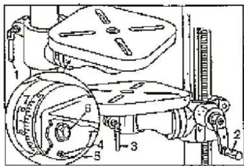
text_image
Technical diagram of a mechanical assembly with numbered components and directional arrows indicating motion or force directions.Slika 16
Slika 17
Dubina bušenja (slika 18)
Za bušenje slijepih otvora vodite mirujuće vreteno bušilice prema dolje da svrdlo dotakne bušeni materijal. Sad popustite vijak za ugađanje dubine te na ljestvici namjestite na "0". Vijak za ugađanje opet zategnite pa na ljestvici pročitajte aktualnu dubinu bušenja.
Povratna opruga vretena (slika 19)
text_image
Exploded view diagram of a mechanical assembly with numbered parts and exploded view indicatorsEC Declaration of Conformity
Ovim izjavljujemo mi, Güde GmbH & Co. KG
We herewith declare, Birkichstrasse 6, 74549 Wolpertshausen, Germany
da su koncepcija i konstrukcija dolje navedenih uređaja u izvedbama koje uvodimo u optjecaj u skladu s odgovarajućim temeljnim zahtjevima direktiva EU-a u pogledu sigurnosti i higijene.
that the following Appliance complies with the appropriate basic safety and health requirements of the EC Directive based on its design and type, as brought into circulation by us.
In a case of alternation of the machine, not agreed upon by us, this declaration will lose its validity.
Oznaka uređaja: - Stolne i stupne bušilice
Machine Description:
Applicable EC Directives: - 2006/42/EG
Korišteni harmonizirani - EN 55014-1:2006
standardi: - EN 55014-2:1997/+A1:2002
Applicable harmonized - EN 61000-3-2:2006
Standards: - EN 61000-3-3:1995/+A1:2001/+A2:2005
- EN 61029-1:2009

Date/Authorized Signature:
Podaci o potpisniku:
Title of Signatory: gospodin Arnold, predstavnik
Sadržaj
ČLANAK STRANA
text_image
Technical diagram of a mechanical assembly with numbered parts for identification and assembly reference.8. Montare
Montare și curățare
text_image
Technical diagram of a mechanical device with numbered parts, including a drill press and various tools.Fig. 1
natural_image
Line drawings of four different wrenches and screwdrivers (no text or labels)Fig. 2
natural_image
Technical line drawing of a mechanical device with mounting base and cylindrical component (no text or symbols)Fig. 3
text_image
Technical diagram of a mechanical assembly with numbered components and cross-sectional viewsFig. 4
text_image
Technical diagram of a mechanical device with numbered parts labeled 1, 2, and 3.Fig. 5

text_image
1 2 3 4 5Fig. 6
text_image
Technical diagram of a mechanical assembly with labeled parts 1 and 2Fig. 7
text_image
Technical diagram of a mechanical device with labeled parts 1 and 2Fig. 8
natural_image
Technical line drawing of an industrial machine with control panel and wiring (no text or symbols)Fig. 9
text_image
Technical diagram of a mechanical assembly with labeled parts 1 and 2Fig. 10
Montarea carcasei rotilor de curea (fig. 11)
text_image
knob washer screwFig. 11
text_image
1 2 3Fig. 12
text_image
Technical diagram of a mechanical assembly with numbered components and a magnified inset viewFig. 13
text_image
Technical diagram showing a mechanical assembly with labeled parts and an inset view of a component.Fig. 14
text_image
Technical diagram of a mechanical device with labeled components and numbered partsFig. 16
Fig. 17
text_image
Technical diagram of a mechanical assembly with numbered components and labeled partsAdâncime de burghiere (fig. 18)
text_image
Technical diagram of a mechanical device with labeled components 1 and 2Fig. 18
text_image
Technical diagram of a mechanical assembly with numbered componentsFig. 19
text_image
Exploded view diagram of a mechanical assembly with numbered parts and exploded view indicatorsEC Declaration of Conformity
Ovim izjavljujemo mi, Güde GmbH & Co. KG
We herewith declare, Birkichstrasse 6, 74549 Wolpertshausen, Germany
da su koncepcija i konstrukcija dolje navedenih uređaja u izvedbama koje uvodimo u optjecaj u skladu s odgovarajućim temeljnim zahtjevima direktiva EU-a u pogledu sigurnosti i higijene.
that the following Appliance complies with the appropriate basic safety and health requirements of the EC Directive based on its design and type, as brought into circulation by us.
In a case of alternation of the machine, not agreed upon by us, this declaration will lose its validity.
Oznaka uređaja: - Stolne i stupne bušilice
Machine Description:
Applicable EC Directives: - 2006/42/EG
Date/Authorized Signature:
Podaci o potpisniku:
Title of Signatory: gospodin Arnold, predstavnik
Съдържание
РАЗДЕЛ СТРАНИЦА
text_image
Technical diagram of an electrical switch or relay with numbered components labeled 1 through 8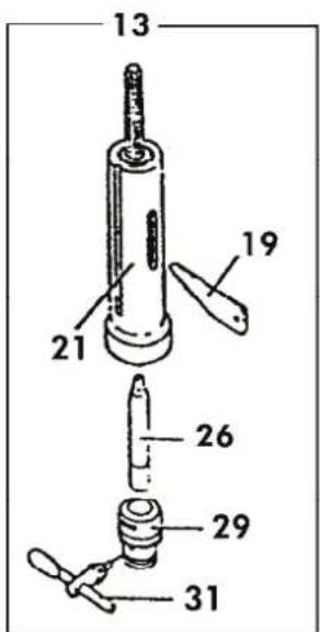
text_image
13 19 21 26 29 31
text_image
Technical diagram of a drill press with numbered parts for identification8. Монтаж
Монтаж и чистене
text_image
Exploded view diagram of a mechanical device with numbered parts and labeled componentsKap. 1
natural_image
Line drawings of four different hand tools: wrench, hammer, screwdriver, and flat (no text or symbols)Kap. 2
natural_image
Technical line drawing of a mechanical component with mounting flanges and cylindrical body (no text or symbols)Kap.
3
text_image
Technical diagram of a mechanical assembly with numbered components and cross-sectional viewsKap. 4
text_image
Technical diagram of a mechanical device with numbered parts labeled 1, 2, and 3.Kap. 5
text_image
5 4 1Kap. 6
text_image
Technical diagram of a mechanical assembly with labeled parts 1 and 2Kap. 7
text_image
Technical diagram of an industrial machine with labeled parts 1 and 2Kap. 8
natural_image
Technical line drawing of an industrial machine with control panel and wiring (no text or symbols)Kap. 9
text_image
Technical diagram of a mechanical assembly with labeled parts 1 and 2Kap. 10
text_image
knob washer screwKap. 11
text_image
2 1 3Kap. 12

text_image
Technical diagram of a mechanical assembly with numbered components and a magnified inset viewKap. 13
text_image
Technical diagram showing a mechanical assembly with labeled parts and an inset view of a component.Kap. 14
9. Регулиране

text_image
Technical diagram of a mechanical device with labeled components and directional arrows indicating motion or flow.Kap. 16
text_image
Technical diagram of a mechanical assembly with numbered components, likely a valve or pump mechanism.Kap. 17
EC Declaration of Conformity
that the following Appliance complies with the appropriate basic safety and health requirements of the EC Directive based on its design and type, as brought into circulation by us.
In a case of alternation of the machine, not agreed upon by us, this declaration will lose ist validity.
Machine Description:
Applicable EC Directives:
- 2006/42/EG
Applicable harmonized
- EN 61000-3-2:2006
Standards:
- EN 61000-3-3:1995/+A1:2001/+A2:2005
- EN 61029-1:2009
Date/Authorized Signature: