
Compass - Stroller Gaggle - Free user manual and instructions
Find the device manual for free Compass Gaggle in PDF.
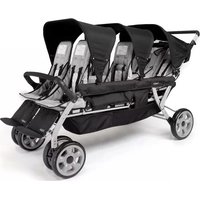
| Product type | Quad stroller (for 4 children) |
| Brand | Gaggle |
| Model | Compass |
| Maximum capacity per child | 15 kg (40 lb) |
| Maximum child height | 114 cm (45 inches) |
| Number of seats | 4 |
| Stroller weight (estimated) | Approximately 15 kg (without children) |
| Folded dimensions (estimated) | Approximately 90 x 60 x 40 cm |
| Frame material | Steel or aluminum (not specified) |
| Wheel type | Double front swivel wheels with lock, rear fixed wheels |
| Brake | Bar parking brake on rear axle |
| Restraint system | Adjustable 5-point harness (shoulder straps, waist belt, crotch strap) |
| Seat recline | 2 positions (front and rear seats) |
| Footrest | Front, 3 positions |
| Canopy | With window and rear cover, removable |
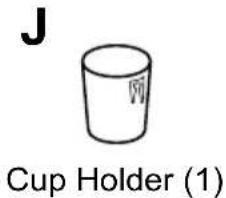
| Cup holder | Included accessory |
| Folding | Mechanical with retaining strap |
| Cleaning | Surface clean with mild soap and water solution |
| Model numbers | 9908932, 9908933 |
| Customer service | 1 866 603-5900 (US), 1 330 722-5033 (outside US) |
Frequently Asked Questions - Compass Gaggle
User questions about Compass Gaggle
0 question about this device. Answer the ones you know or ask your own.
Ask a new question about this device
Download the instructions for your Stroller in PDF format for free! Find your manual Compass - Gaggle and take your electronic device back in hand. On this page are published all the documents necessary for the use of your device. Compass by Gaggle.
USER MANUAL Compass Gaggle
5216 Portside Dr, Medina, OH 44256 USA
• PH: 1 330.722.5033 • FAX: 1 330.722.5037
gagglestrollers.com
IMPORTANT - Keep these instructions for future reference.
Gaggle® Compass™ Quad Stroller
Models Covered: 9908932, 9908933
FOR CUSTOMER SERVICE CALL 1-877-716-2757 (outside of U.S. 330-722-5033). DO NOT CALL RETAILER OR RESELLER FOR SERVICE AS THEY ARE NOT AUTHORIZED TO RESOLVE ANY SERVICE ISSUES.
FOR WARRANTY AND FEDERAL SAFETY STANDARD COMPLIANCE CERTIFICATES, PLEASE VISIT OUR WEBSITE AT gagglestrollers.com
natural_image
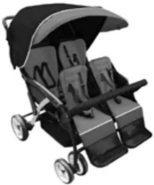
Black and white photo of a baby stroller with open canopy and matching compartments (no text or symbols visible)Color and Style May Vary.
ASSEMBLY INSTRUCTIONS
• Adult assembly required.
- Read all instructions BEFORE assembly and use.
- Unpack carton, remove packing materials, safely dispose of properly or recycle where possible.
Record product information found on the frame tube here.
Manufacture Date: ____
Model Number: ____
Purchase Order: ____
WARNING
This stroller is for use of not more than 4 children. For use with children whose weight is 40 lbs max as tested per US 16 CFR 1227 and 15 kg max as tested per BS EN 1888.
For use with children whose height is 45 inches, (114 cm) or less. Children MUST be buckled in the seats with harness properly adjusted.
Table of Contents
Table of Contents....2
Warnings....3
Assembly instructions
Tools and parts....4
Step 1- Rear Axle and Brake Assembly....5
Step 2 - Rear Wheel Assembly....5
Step 3 - Front Wheel Assembly....6
Step 4 - Arm bar Assembly....6
Step 5 - Canopy Assembly....7
Step 6 - Canopy Removal / Cup Holder Assembly......8
Stroller operation and Use
Unfolding and Folding Stroller....9
Securing Children in Stroller....11
Seat Back Recline Adjustment....12
Parking Brake Operation....13
Front Wheel Swivel Lock Operation....13
Arm bar Removal and Replacement....14
Canopy Operation....15
Stroller maintenance
Cleaning....15

WARNING

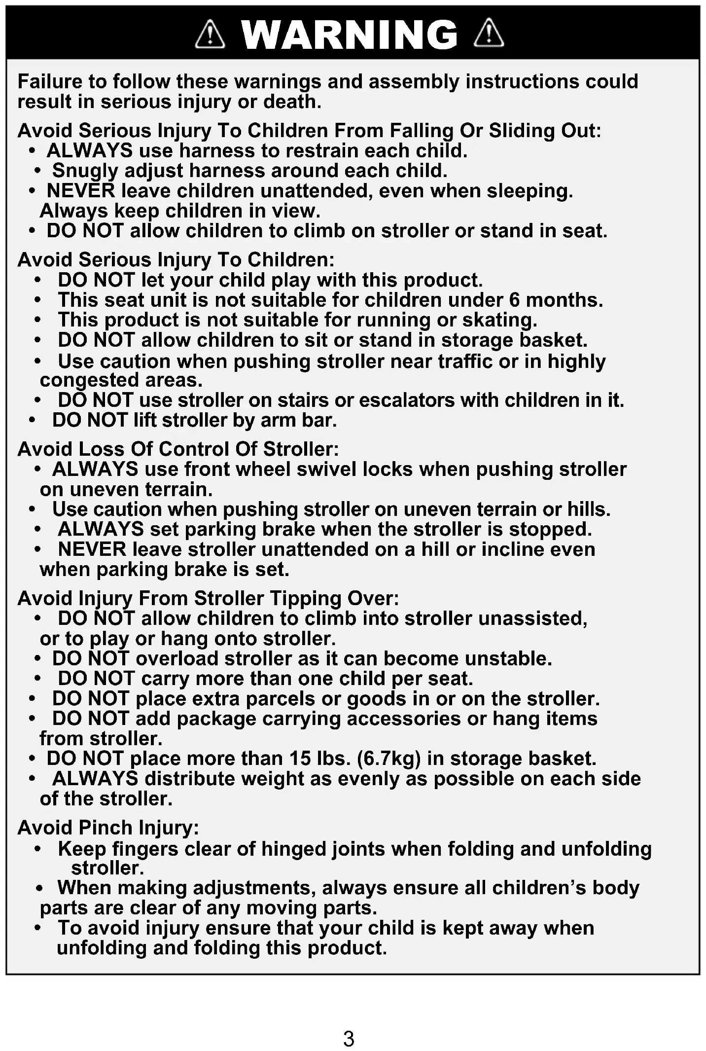
Failure to follow these warnings and assembly instructions could result in serious injury or death.
Avoid Serious Injury To Children From Falling Or Sliding Out:
• ALWAYS use harness to restrain each child.
- Snugly adjust harness around each child.
- NEVER leave children unattended, even when sleeping. Always keep children in view.
- DO NOT allow children to climb on stroller or stand in seat.
Avoid Serious Injury To Children:
• DO NOT let your child play with this product.
- This seat unit is not suitable for children under 6 months.
• This product is not suitable for running or skating.
• DO NOT allow children to sit or stand in storage basket.
- Use caution when pushing stroller near traffic or in highly congested areas.
- DÔ NOT use stroller on stairs or escalators with children in it.
• DO NOT lift stroller by arm bar.
Avoid Loss Of Control Of Stroller:
- ALWAYS use front wheel swivel locks when pushing stroller on uneven terrain.
- Use caution when pushing stroller on uneven terrain or hills.
• ALWAYS set parking brake when the stroller is stopped. - NEVER leave stroller unattended on a hill or incline even when parking brake is set.
Avoid Injury From Stroller Tipping Over:
- DO NOT allow children to climb into stroller unassisted, or to play or hang onto stroller.
- DO NOT overload stroller as it can become unstable.
• DO NOT carry more than one child per seat.
• DO NOT place extra parcels or goods in or on the stroller. - DO NOT add package carrying accessories or hang items from stroller.
- DO NOT place more than 15 lbs. (6.7kg) in storage basket.
- ALWAYS distribute weight as evenly as possible on each side of the stroller.
Avoid Pinch Injury:
- Keep fingers clear of hinged joints when folding and unfolding stroller.
- When making adjustments, always ensure all children's body parts are clear of any moving parts.
- To avoid injury ensure that your child is kept away when unfolding and folding this product.
Assembly Instructions
TOOLS REQUIRED: Phillips screwdriver
- Read all instructions before ASSEMBLY and USE of Stroller.
- Unpack carton, remove packing materials, including polybag. Identify and check all parts. If parts are missing or damaged, call Gaggle® for assistance at 877.716.2757 (USA Only) or 330.722.5033.
- Discard all packing materials after assembly.

WARNING

- Choking Hazard - Stroller assembly hardware includes small parts. Keep small parts away from children.
- Plastic bags can cause suffocation. Keep plastic bag away from children. Remove and discard plastic bags.
- Pinch Hazard - Keep hands clear of moving parts during assembly, folding and unfolding.
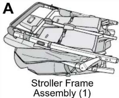
Parts

natural_image
Diagram of a rear wheel with axle (2), showing two views: front and side (no text or symbols on the diagram itself)

natural_image
Technical illustration of front wheel assembly (2), showing two components with no text or symbols
natural_image
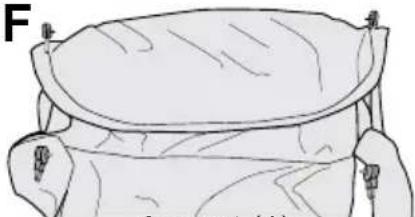
Illustration of a canopy structure with labeled parts (no text or symbols beyond label)![H Screw [M6 x 34 mm] (2)](/content/2026/04/636975/images/cfcff29648b52610210a8589cf5605db6ed3c3a529d255f2105f7856c3aadd6e.jpg)

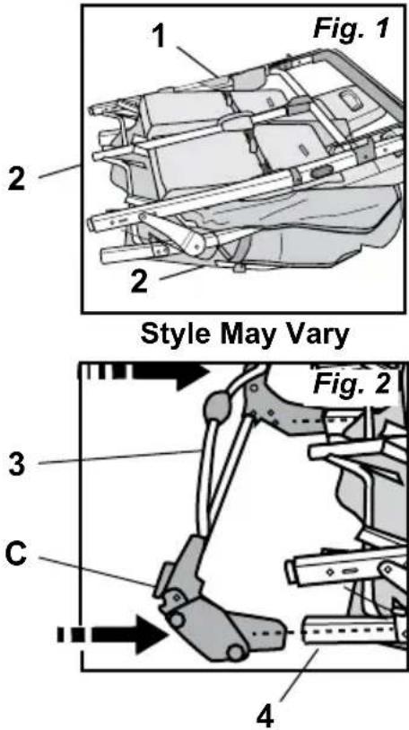
STEP 1 - Rear Axle and Brake Assembly
-
Lay folded Stroller Frame Assembly (A) on clean floor with handle tube (1) on top and front footrests (2) contacting floor (Fig. 1).
-
Assemble Rear Axle Tube Assembly (C) to stroller (Fig. 2).
-
Position Rear Axle Tube Assembly (C) with brake tube (3) up and open end of rear axle assemblies toward rear legs.
- Slide rear axle tube assembly (C) onto the lower ends of rear legs (4) until contacting spring pins. Press spring pins and slide rear axle assembly (C) onto rear leg (4) until spring pins snap into holes in rear axle tube assembly (C).
- Pull on Rear Axle Tube Assembly (C) to check that it is secured onto rear legs.
STEP 2 - Rear Wheel Assembly
- Align hole in rear axle rod of Rear Wheel With Axle B with holes in Rear Axle Tube Assembly (C). Slide rear wheel with axle B into Rear Axle Tube Assembly (C) (Fig. 1).
- Slide Rear Wheel With Axle (B) in until hole in rear axle rod 1 aligns with hole in rear axle tube.
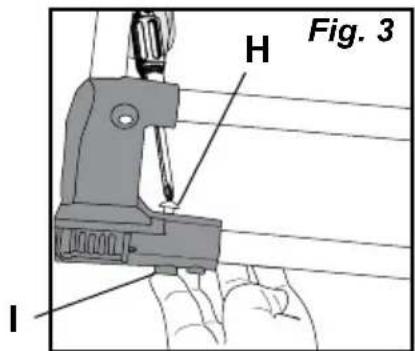
- Insert M6 x 34 mm Screw (H) through Rear Axle Tube Assembly (C) and rear axle rod until screw comes out bottom of Rear Axle Tube Assembly (C) (Fig. 2).
NOTE: If end of screw does not slide into hole, check alignment of hole in axle. If hole in axle is not aligned, remove rear wheel and start over.
- Insert M6 Nut (I) into 6-sided recess on bottom of rear axle tube and using phillips screwdriver, secure Screw (H) by turning into nut until tight (Fig. 3).
Repeat steps 2 thru 4 for opposite rear wheel.


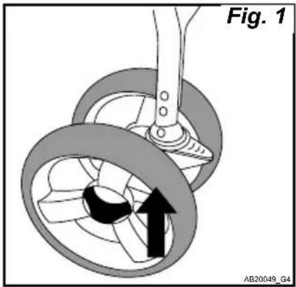
STEP 3 - Front Wheel Assembly
-
Align pivot shaft of stroller frame with hole in wheel assembly. Wheel locking lever should be facing up. Slide wheel assembly onto pivot shaft until a solid click is heard and felt from the buttons engaging. (Fig. 1)
-
Check the wheel is secure by pulling down on the wheels. Wheels should stay securely in place.
natural_image
Mechanical diagram showing a rotating wheel assembly with a directional arrow indicating motion (no text or symbols)STEP 4 - Arm Bar Assembly
- Slide Arm Bar Clamp (1) between fabric seat side cover and front leg. Push Arm Bar Clamp (1) onto front leg and align the hole in the clamp with the Stud (2) on the arm, on both sides of the stroller (Fig. 1)
- Lock Arm Bar to stroller frame by pushing Arm Bar Clamp (1) around front leg tube (4). Close the Lock lever by pressing the lock lever onto the Arm bar until it clicks closed and the stud (2) is fully through the hole in the lever. (Fig. 2).
- Repeat step 2 for opposite end of Arm Bar Check that the Arm bar is securely attached.
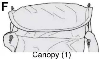
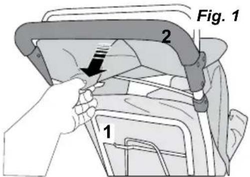
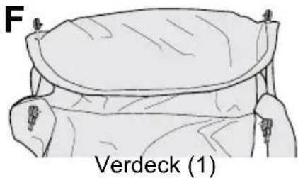
STEP 5 - Canopy Assembly
To attach canopy:
- Position canopy with rounded front section on top and place canopy in rear seat area and over top of front seats.
- Secure Main Canopy Tube (long tube) by pushing end of Main Canopy Tube into Canopy Retainer slot located on outside of handle near the armrest (Fig. 1).
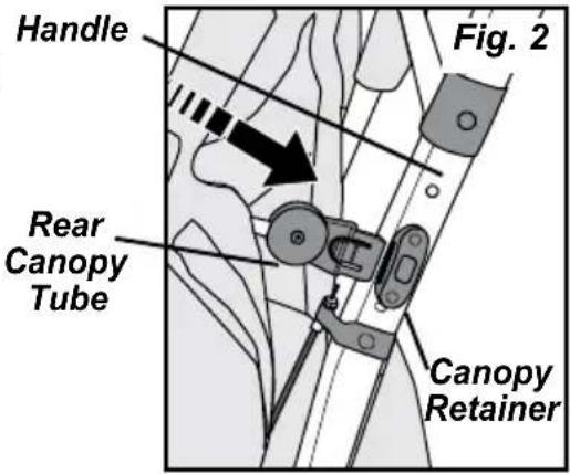
- Secure short Rear Canopy Tube (short tube) by pushing end of Canopy Tube into Canopy Retainer slot located on outside of the handle near the top of the back seat (Fig. 2).
Repeat steps 2 and 3 to secure canopy tubes on other side of stroller.
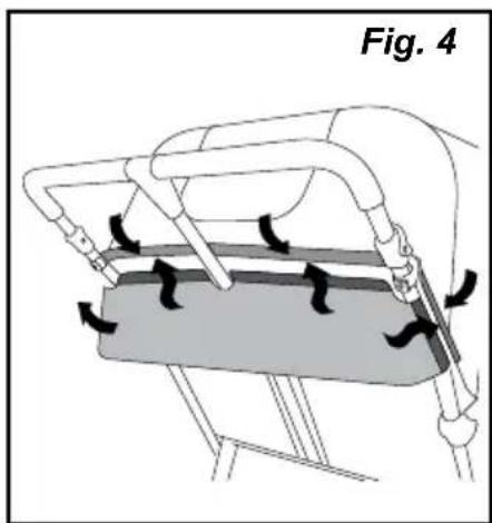
- Secure back of canopy.
Secure canopy sides around stroller handle by securing hook & loop fasteners on each side (Fig. 3).
Repeat on other side of canopy.

- Attach Rear Cover.
With the loop side of fabric fastener facing outwards, align cut out in the center of the Rear Cover with the center tube of the stroller handle. Press the hook and loop fabric fastening together on both sides of the center tube.
Wrap each side of the back cover around the side handle tube and press together the loop side of the Rear Cover to the Hook side of the Main Canopy. (Fig. 4)

natural_image
Diagram of a mechanical device with directional arrows indicating motion or force, labeled 'Fig. 4' (no text or symbols on diagram itself)STEP 6 - Canopy Removal
To remove canopy:
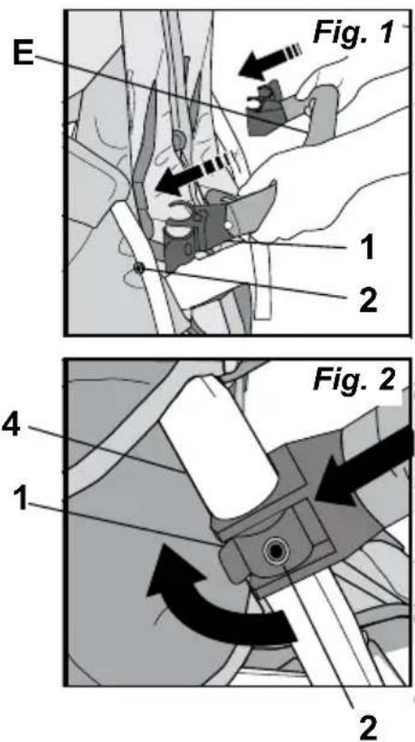
- Open sides of canopy around stroller handle by pulling fabric hook & loop fasteners apart (1) (Fig. 1).
- Pull rear panel of canopy up and out of opening between stroller handle and handle support (2).
- Remove canopy from rear support tube by releasing hook & loop fasteners.
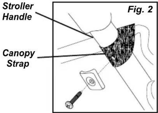
- Remove screw, retainer, and canopy strap from handle. (Fig. 2)
- Remove rear canopy tube (short tube) by pressing retainer tab in (1) and sliding rear canopy tube up (2) (Fig. 3).
- Repeat step 5 for opposite side of stroller.
- Remove main canopy tube (long tube) by pressing retainer tab in (1) and sliding main canopy tube up (2) (Fig. 3).
- Repeat step 7 for opposite side of stroller.

Retainer Tab
Cup Holder Assembly
Cup Holder Assembly
Push down Cup Holder (J) to secure in place. Cup Holder key slot fits into button on side of stroller handle.
See Figure 1.
- Only use Gaggle® provided or approved accessories for this stroller.

Stroller Operation and Use
Unfolding and Folding Stroller:

WARNING

- Pinch Hazard - Keep hands clear of moving parts during assembly, folding and unfolding.
- Ensure that all the locking devices are engaged before use.
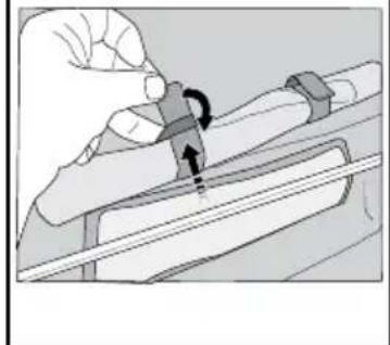
Unfolding and Folding Stroller
To unfold stroller:
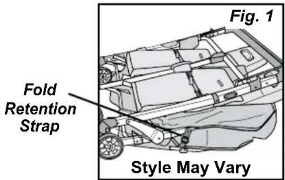
- Lay stroller on floor with front wheels and front footrests down, contacting the floor (Fig. 1).
NOTE: Always check that floor is clean and dry before laying stroller on floor. - Lock parking brake.
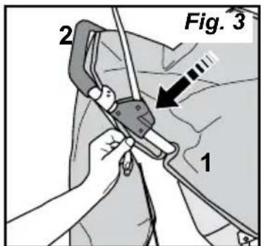
- Locate Fold Retention Strap on one side of the stroller (Fig. 1). Push down on stroller handle and unhook Fold Retention Strap by pulling up on the loop (1) and then turn (2) and slide the loop through the "D" Ring (3) (Fig. 2 and 3).
- Repeat step 2 on opposite side to unhook Fold Retention Strap.
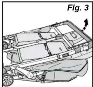
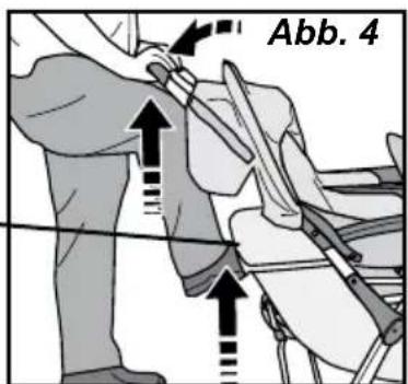
- Pull up on handle to unfold the stroller (Fig. 3) and then with a quick snap, push down on handle to lock in unfolded position (Fig. 4).
Push down on side frame to ensure stroller is in locked open position.
Lift on handle to check that stroller handle is locked in the unfolded position on both sides.

natural_image
Technical line drawing of a car chassis with visible internal compartments and wheels (no text or symbols)
Unfolding and Folding Stroller
To unfold stroller (continued):
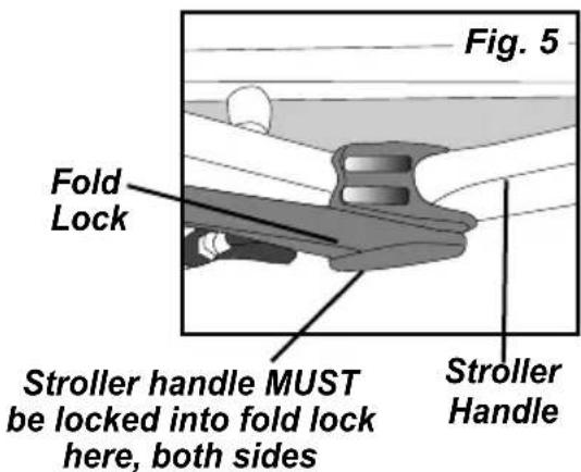
- Visually check that the stroller handle is securely locked into the fold Lock assembly on both sides of the stroller. (Fig. 5).
NOTE: If fold lock is not locked, fold lock can be locked by pressing down on front of armrests and then press down on top of stroller handle.
To fold stroller:
- Place seat back of front seats in the upright adjustment position.
NOTE: Seat backs of front seats must be in the upright position when folding.
-
Push down on Red Release lever on right side and then slide both Fold Lock Release collars on both sides up toward the handle grip to unlock (Fig. 1).
-
While holding the Fold Lock Releases up, push forward on the stroller handle to fold (Fig. 1).
-
Secure stroller in folded position by laying stroller on floor with front wheels and front footrests down. Push down on stroller handle and slide the loop on the Fold Retention Strap through the "D" Ring and rotate to secure in place (Fig. 2).


WARNING

Avoid Serious Injury To Children From Falling Or Sliding Out:
• ALWAYS use a harness to restrain each child.
- Snugly adjust harness around each child.
- NEVER leave children unattended, even when sleeping. Always keep children in view.
• DO NOT allow children to climb on stroller or stand in seat.
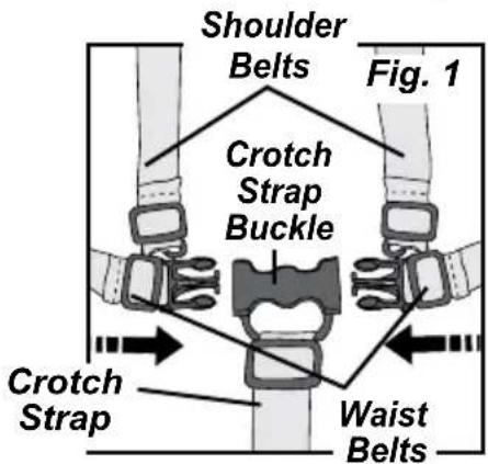
- With harness unbuckled, place child in seat.
- Secure child with harness by positioning Crotch Strap between child's legs and placing Shoulder and Waist Belts over shoulders and thighs. Snap buckle tongues into crotch strap buckle (Fig. 1).
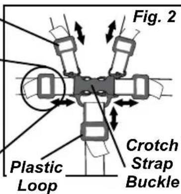
- Snugly adjust each strap by pulling on the free end of the strap and moving plastic loop along strap (Fig. 2).
Shoulder Belt Height Adjustment:
Use shoulder belt slots that are closest to child's shoulders.
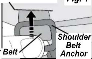
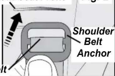
To change shoulder belt height:
- Remove shoulder belt from seat back of seat - on back of seat, tip shoulder belt anchor in line with shoulder belt and then push belt anchor and shoulder belt through slot in seat back (Fig. 1).
- Reattach shoulder belt to seat back - on front side of seat, tip shoulder belt anchor to contact shoulder belt, push belt anchor and shoulder belt through slot in seat back at desired height. Rotate belt anchor to lay flat on back of seat (Fig. 2). Repeat for opposite shoulder belt.
Crotch Belt Adjustment:
- To lengthen crotch belt - slide plastic loop up on crotch belt (Fig. 2).
- To shorten crotch belt - slide plastic loop down on crotch belt (Fig. 2).
Plastic Loop
Slot in Seat Back
Slot in Seat Front
Shoulder Belt
Seat Back Recline Adjustment
Seat Back Recline Adjustment:
The seat backs have two recline positions.
Front seat adjustment:
NOTE: The seat back must be in the upright position when folding the stroller.
To recline seat back:
- Pull up on seat back Recline Handle (Fig. 1).
- Lower seat back to recline position and release seat back recline handle.
To raise seat back into upright position:
- Pull up on seat Back Recline Handle (Fig. 1).
- Pull seat back forward to upright position and release seat Back Recline Handle.
- Check that seat back is locked.
Rear seat adjustment:
To recline seat back:
- While holding seat back up, release both Seat Back Buckles (Fig. 2).
- Lower seat back into reclined position.
To raise seat back into upright position:
- Push seat back up and forward to upright position and fasten both Seat Back Buckles (Fig. 2).


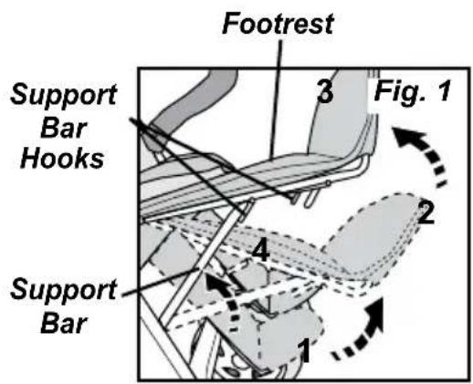
Footrest Adjustment:
The front footrests have three adjustment positions.
To raise footrests:
- Lift footrest up to one of the two raised positions and rotate support bar up (4) and place under support bar hooks on footrest (Fig. 1).
To lower footrests:
- Lift up on footrest and allow support bar to drop down out from under support bar hooks.

WARNING

• Always lock parking brake when stroller is stopped and when loading and unloading children.
To lock parking brake:
- Press down on parking brake lock bar on the rear axle assembly into locked position (Fig. 1).
- Check that wheels are locked.
Parking
Brake -
Lock Bar

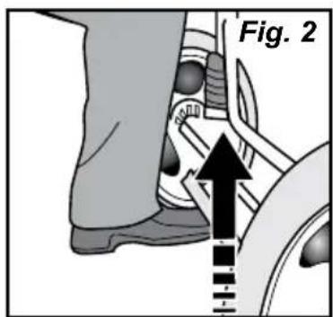
To unlock parking brake:
- Place toe under parking brake lock bar and lift up into unlocked position (Fig. 2).
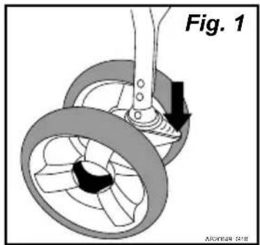
Front Wheel Swivel Lock Operation.

WARNING

• Always use front wheel swivel locks when pushing stroller on uneven ground.
To lock Wheel Assembly:
- Rotate front wheel assembly until it is pointing Forward.(Fig. 1).
- Push down swivel lock until it snaps in place.
- Check that front swivel is securely locked by pushing side to side on front wheel assembly.
- Repeat steps 1 through 3 for other wheel Assembly.
natural_image
Mechanical diagram showing a rotating wheel with a shaft and gear mechanism, labeled Fig. 1 (no text or symbols on the diagram itself)Front Wheel Swivel Lock Operation.
To Unlock Wheel Assembly:
- Push swivel lock up to release (Fig. 1).
- Repeat for other wheel assembly.

natural_image
Mechanical diagram showing a pulley system with a lever and wheel assembly, labeled Fig. 1 (no text or symbols on the diagram itself)Arm Bar Removal and Replacement.
To remove arm bar
- Pull arm bar clamp lock lever out away from stroller to unlock arm bar from stroller frame (1). (Fig 1)
- Pull out on arm bar to remove it from stroller frame (2) (Fig 1)
To replace arm bar
See step 4 in the assembly instructions, Arm Bar Assembly.
- Only use Gaggle® provided or approved accessories for this stroller.
Canopy Operation
To extend canopy:
- Pull main canopy tube forward (1) (Fig. 1).
- Rotate front section of canopy forward (2) (Fig. 1).
To retract canopy:
- Rotate front section of canopy back over top of canopy (1) (Fig. 2).
- Pull main canopy tube toward rear of stroller (2) (Fig. 2).
To operate canopy window:
- Roll canopy window up towards top of canopy.
- Thread hook & loop fastener through sewn loop on back edge of canopy, fold over sewn loop and press strap together (Fig. 3).
Repeat for other fastener.

Style May Vary
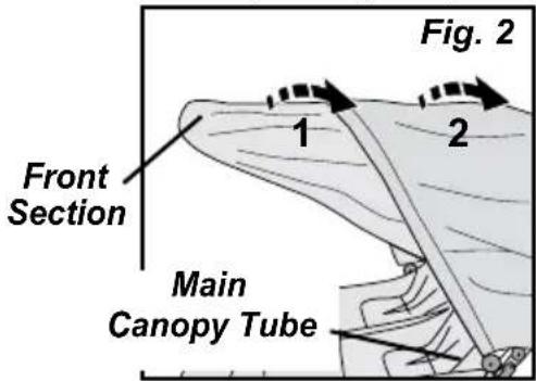
Fig. 3
natural_image
Illustration of a hand adjusting a mechanical component with a curved arrow indicating rotation (no text or symbols present)Stroller Maintenance
Cleaning seats, harness, armrests, arm bar and canopy:
- Surface wash only with mild solution of soap and water.
- Rinse with water to remove soap solution.
Cleaning Stroller:
- Surface wash stroller frame, plastic parts and fabric with mild solution of soap and water. Wipe surfaces with water to remove soap solution.
- Wipe or air dry.
5216 Portside Dr, Medina, OH 44256 USA
• TEL: 1 330.722.5033 • FAX: 1 330.722.5037
gagglestrollers.com
natural_image
Black and white illustration of a baby stroller with two compartments and wheels (no text or symbols)natural_image
Technical illustration of a mechanical assembly with no visible text or symbolsnatural_image
Technical illustration of a mechanical component with a circular fan and shaft (no text or symbols)natural_image
Diagram of a mechanical linkage or suspension system with two vertical supports and a central oval component (no text or symbols)natural_image
Technical illustration of two mechanical components: a multi-cylinder wheel and a three-bladed fan (no text or symbols)natural_image
Illustration of a curved, segmented biological structure resembling a larva or larva (no text or symbols)Barra reposabrazos (1)

natural_image
Line drawing of a garment sleeve with clamps, no text or symbols presentCapota (1)

natural_image
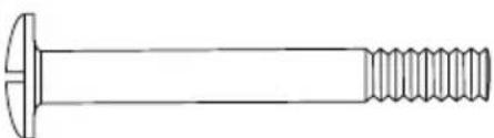
Technical line drawing of a bolt with threaded shaft (no text or symbols)Tornillo [M6 x 34 mm] (2)
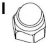
Tuerca [M6] (2)

Posavasos (1)
natural_image
Diagram of a mechanical assembly with two wheels and a pull rod, showing a directional arrow (no text or symbols)natural_image
Diagram of a mechanical device with directional arrows indicating motion or force, labeled 'Fig. 4' (no text or symbols on diagram itself)natural_image
Technical line drawing of a vehicle chassis with labeled component 'Fig. 3' (no text or symbols on diagram itself)natural_image
Mechanical diagram showing a pulley system with rotating wheels and a lever, labeled Fig. 1 (no text or symbols on the diagram itself)natural_image
Illustration of a hand holding a tool interacting with a device (no text or symbols visible)natural_image
Black and white illustration of a baby stroller with open canopy and matching compartments (no text or symbols)natural_image
Technical illustration of a mechanical assembly with no visible text or symbolsnatural_image
Simple line drawing of a mechanical linkage or suspension system with two vertical supports and a central circular component (no text or symbols)natural_image
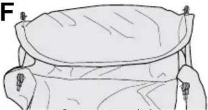
Illustration of a curved, segmented object resembling an arthropod or larva (no text or symbols)Guidon (1)
F
natural_image
Illustration of a garment sleeve with handles and a flat collar (no text or symbols)Auvent (1)
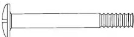
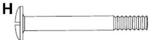
H
natural_image
Technical line drawing of a bolt with threaded shaft (no text or symbols)Vis [M6 x 34 mm] (2)
|

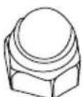
Écrous [M6] (2)
J
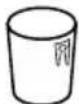
Porte-gobelet (1)
natural_image
Mechanical diagram showing a rotating wheel assembly with a directional arrow indicating motion (no text or symbols)natural_image
Medical illustration of a surgical tool applied to a tissue sample, labeled Fig. 3 (no text or symbols on the diagram itself)
natural_image
Diagram of a mechanical device with arrows indicating motion or force direction, labeled 'Fig. 4' (no text or symbols on diagram itself)natural_image
Diagram of a car interior showing structural components and a directional arrow, labeled 'Fig. 3' (no text or symbols on the diagram itself)natural_image
Mechanical diagram showing a wheel assembly with a rotating shaft and gear mechanism, labeled Fig. 1 (no text or symbols on the diagram itself)natural_image
Mechanical diagram showing a pulley system with a force arrow, labeled Fig. 1 (no text or symbols on the diagram itself)natural_image
Illustration of a hand using a tool to adjust or install a mechanical component, labeled 'Fig. 3' (no text or symbols on the diagram itself)natural_image
Black and white photo of a baby stroller with matching bags, no visible text or symbolsFarbe und
Ausführung
können variieren.
MONTAGEANLEITUNG
natural_image
Diagram of a mechanical component with labeled 'Hinterrad mit Achse (2)' and a side view showing a shaft and wheel (no text or symbols beyond label)
natural_image
Technical illustration of a Vorderrad component, showing two views (D and 2) with no visible text or symbols.
natural_image
Diagram of a geological or mechanical structure with labeled features, no readable text or symbols present.![H Schrauben [M6 x 34 mm] (2)](/content/2026/04/636975/images/43b90df17698413182fc6b94a748ee748cb6a71a732b609e6c7e89fa12d8ed2d.jpg)
![I Mutter [M6] (2)](/content/2026/04/636975/images/5ec02c0d6e3e72b4543234764a551461e4733c85bc43de2594946f701390e5de.jpg)

natural_image
Diagram of a car interior showing structural components and a directional arrow (no text or symbols)Hintere Korbstange
natural_image
Illustration of a hand holding a tool interacting with a mechanical component (no text or symbols visible)natural_image
Black and white illustration of a baby stroller with three seats and a canopy (no text or symbols)natural_image
Technical diagram of a mechanical assembly with no visible text or symbolsnatural_image
Simple line drawing of a mechanical linkage or suspension system with two vertical supports and a central oval component (no text or symbols)natural_image
Illustration of a curved, segmented biological structure with textured surface (no text or symbols)Bracciolo (1)
F
natural_image
Anatomical line drawing of a biological structure, possibly a larva or cage, with no visible text or labels.Capottina (1)
H
natural_image
Technical line drawing of a bolt with threaded shaft (no text or symbols)Vite [M6 x 34 mm] (2)
|
Dado [M6] (2)
J

Portabicchieri (1)
natural_image
Diagram of a mechanical assembly with two wheels and a lever, showing motion direction (no text or symbols)natural_image
Medical illustration showing surgical tools manipulating tissue (no text or symbols)natural_image
Diagram of a mechanical device with directional arrows indicating motion or force, labeled 'Fig. 4' (no text or symbols on diagram itself)natural_image
Technical illustration of a car chassis with structural components and an arrow indicating direction (no text or symbols present)natural_image
Mechanical diagram showing a wheel assembly with a pull rod and directional arrow, labeled Fig. 1 (no text or symbols on the diagram itself)natural_image
Mechanical diagram showing a wheel assembly with a pull rod and labeled component 'Fig. 1' (no text or symbols on the diagram itself)natural_image
Illustration of a hand using a tool to adjust or install a mechanical component, labeled 'Fig. 3' (no text or symbols on the diagram itself)natural_image
Black and white illustration of a baby stroller with open canopy and matching compartments (no text or symbols)natural_image
Technical illustration of a mechanical assembly with no visible text or symbolsnatural_image
Technical illustration of a mechanical component with a side view showing a shaft and fan assembly (no text or symbols)natural_image
Diagram of a mechanical linkage or suspension system with two vertical supports and connecting rods (no text or labels)natural_image
Technical illustration of two mechanical components: a cylindrical housing and a wheel with a central hub (no text or symbols)Передние колеса (2)

natural_image
Illustration of a curved, segmented object resembling a lampshade or tunnel (no text or symbols)natural_image
Line drawing of a mechanical component with a circular top and side connectors (no text or symbols)Капюшон (1)
natural_image
Technical line drawing of a bolt with threaded shaft (no text or symbols)Винты [M6 x 34 mm] (2)
Гайки [M6] (2)
J
Подстаканник (1)


- Gaggle® Compass™ Quad Stroller
- ASSEMBLY INSTRUCTIONS
- WARNING
- Table of Contents
- Table of Contents....2
- Warnings....3
- Stroller operation and Use
- Stroller maintenance
- TOOLS REQUIRED: Phillips screwdriver
- Parts
- STEP 1 - Rear Axle and Brake Assembly
- STEP 2 - Rear Wheel Assembly
- STEP 3 - Front Wheel Assembly
- STEP 4 - Arm Bar Assembly
- STEP 5 - Canopy Assembly
- To attach canopy:
- STEP 6 - Canopy Removal
- To remove canopy:
- Cup Holder Assembly
- Unfolding and Folding Stroller:
- Unfolding and Folding Stroller
- To unfold stroller:
- To unfold stroller (continued):
- To fold stroller:
- Shoulder Belt Height Adjustment:
- To change shoulder belt height:
- Crotch Belt Adjustment:
- Seat Back Recline Adjustment
- Seat Back Recline Adjustment:
- To recline seat back:
- Footrest Adjustment:
- To raise footrests:
- To lower footrests:
- To lock parking brake:
- To unlock parking brake:
- Front Wheel Swivel Lock Operation.
- To lock Wheel Assembly:
- To Unlock Wheel Assembly:
- Arm Bar Removal and Replacement.
- To remove arm bar
- To replace arm bar
- Canopy Operation
- To extend canopy:
- To retract canopy:
- To operate canopy window:
- Cleaning seats, harness, armrests, arm bar and canopy:
- Cleaning Stroller:
- MONTAGEANLEITUNG
Brand : Gaggle
Model : Compass
Category : Stroller