
MCR-S-1/5-UI-DCI-NC - Measuring equipment Phoenix Contact - Free user manual and instructions
Find the device manual for free MCR-S-1/5-UI-DCI-NC Phoenix Contact in PDF.
User questions about MCR-S-1/5-UI-DCI-NC Phoenix Contact
0 question about this device. Answer the ones you know or ask your own.
Ask a new question about this device
Download the instructions for your Measuring equipment in PDF format for free! Find your manual MCR-S-1/5-UI-DCI-NC - Phoenix Contact and take your electronic device back in hand. On this page are published all the documents necessary for the use of your device. MCR-S-1/5-UI-DCI-NC by Phoenix Contact.
USER MANUAL MCR-S-1/5-UI-DCI-NC Phoenix Contact
www.phoenixcontact.com
MNR 9001124 / 2011-07-27
DE Strommessumformer
EN Current Measuring Transducer
FR Transducteur d'intensité (Convertisseur de courant)
ES Convertidores de corriente
RU Измерительный преобразователь сигнала тока
Table of Contents Page
- Before start-up 16
- Description ....17
- Block diagram 17
- Electrical connection and operation
4.1. Electrical connection 18
4.2. Start-up 18
4.3. Functional diagram for configuration 19
4.4. Software package (adapter) 24 - Sample applications ......25
- Technical Data....26
- Appendix
7.1. Order Key 66
Sommaire Page
line
Endwert-(SPAN-)VerhaltenOFFSET-(ZERO-)Verh | Line Chart | X-axis Label | Y-axis Label | Line Style | |---|---|---|---| | Left Chart | -100 | 0 | Solid Line | | Left Chart | -25 | 25 | Dashed Line | | Left Chart | 100 | 110 | Solid Line | | Right Chart | -100 | -110 | Solid Line | | Right Chart | -25 | -100 | Dashed Line | | Right Chart | 100 | 100 | Solid Line | | Left Chart | +25 | 110 | +25% SPAN | | Left Chart | -25 | 100 | -25% SPAN | | Right Chart | +25 | 110 | +25% SPAN | | Right Chart | -110 | 100 | -110% SPAN | Abb.6a Abb.6bAbgleichaufbau:
flowchart
graph LR
    A["Signaleingang"] --> B["A"]
    B --> C["MCR-S"]
    C --> D["V"]
    D --> E["U_A"]
    E --> F["A"]
    F --> G["Signalausgang"]
    H["Betriebsspannung"] --> I["A"]
    I --> J["I_A"]
    style C fill:#f9f,stroke:#333
    style F fill:#ccf,stroke:#333
Cl. I Div. 2, Groups A, B, C and D or Non-Hazardous Locations Only
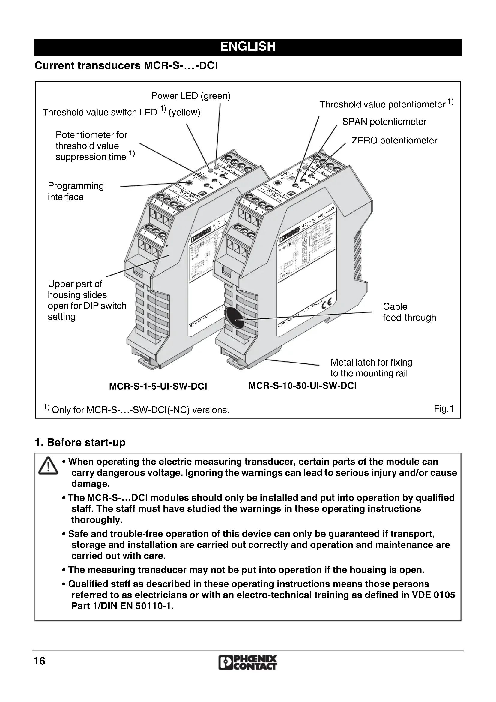
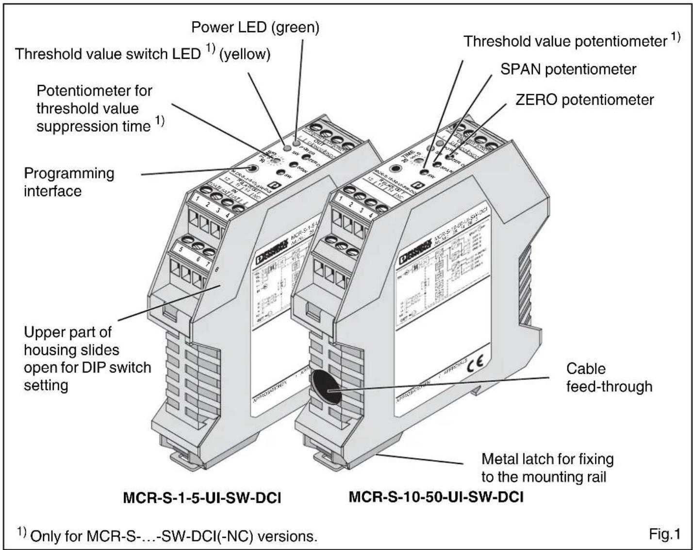
Current transducers MCR-S-...-DCI
1. Before start-up

- When operating the electric measuring transducer, certain parts of the module can carry dangerous voltage. Ignoring the warnings can lead to serious injury and/or cause damage.
- The MCR-S-...DCI modules should only be installed and put into operation by qualified staff. The staff must have studied the warnings in these operating instructions thoroughly.
- Safe and trouble-free operation of this device can only be guaranteed if transport, storage and installation are carried out correctly and operation and maintenance are carried out with care.
- The measuring transducer may not be put into operation if the housing is open.
- Qualified staff as described in these operating instructions means those persons referred to as electricians or with an electro-technical training as defined in VDE 0105 Part 1/DIN EN 50110-1.
2. Description
The MCR-S-...-DCI, active current transducers convert direct, alternating and distorted currents from 0...0.2 A to 0...11 A (MCR-S-1-5-...-DCI) and from 0...9.5 A to 0...55 A (MCR-S-10-50-...-DCI) to analog standard signals.
On the output side, the analog standard signals of 0(4)...20 mA, 0(2)...10 V, ±10 V, 0(1)...5 V, ±5 V with simple (e.g. 0...10 V) and inverse (e.g. 10...0 V) signal flow direction can be used.
An option for the current transducers with threshold output (MCR-S-...-SW-DCI) is a PNP transistor switching output (80 mA) and a relay switching output (2 A).
2.1. Method of operation
Connecting to the input terminal blocks (MCR-S-1-5-...-DCI), or passing the live conductor through the current transducer (MCR-S-10-50-...-DCI) evokes a magnetic flow in the annular strip-wound core.
The density of magnetic flow is measured with the aid of a Hall sensor and converted proportionally from the input current to a voltage (Hall voltage). A downstream true r.m.s. converter enables DC, AC and distorted currents to be measured. The signal is amplified for further conditioning and made available at the output as a proportional analog signal.
2.2. Versions
This package insert is valid for the following types of current transducers:
| Type | Order No. | Measuring range | Threshold value function | |
| MCR-S-1-5-UI-DCI 2814634 0...0,2 A | to0...11 A | no | 1) | |
| MCR-S-1-5-UI-DCI-NC 2814715 no | 2) | |||
| MCR-S-1-5-UI-SW-DCI 2814650 yes | 1) | |||
| MCR-S-1-5-UI-SW-DCI-NC 2814731 yes | 2) | |||
| MCR-S-10-50-UI-DCI | 2814647 0...9,5 A | no | 1) | |
| MCR-S-10-50-UI-DCI-NC | 2814728 no to0...55 A | 2) | ||
| MCR-S-10-50-UI-SW-DCI | 2814663 yes | 1) | ||
| MCR-S-10-50-UI-SW-DCI-NC | 2814744 yes | 2) | ||
1) Configuration is done using the order key following user specifications.
2) The module is supplied in the standard configuration.
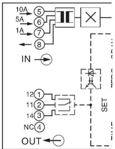
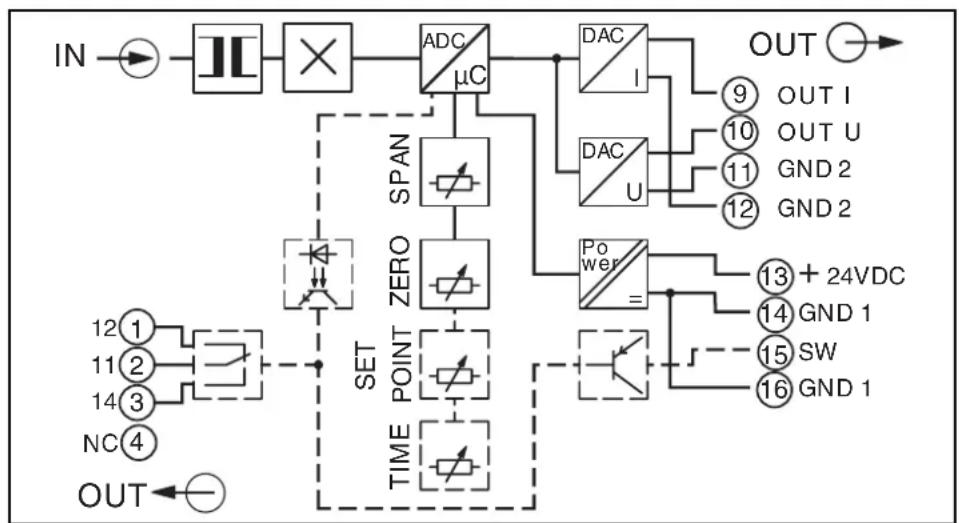
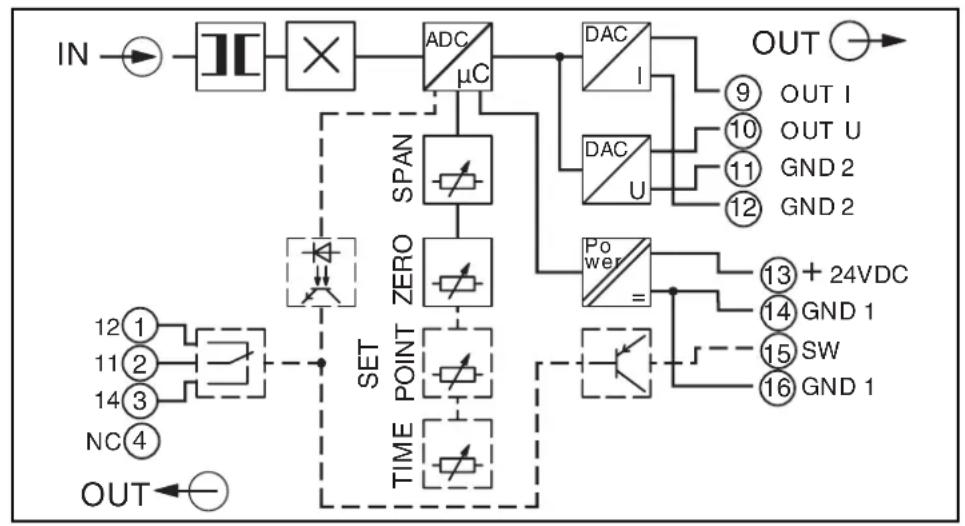
3. Block diagram
flowchart
graph TD
    A["10A"] --> B["5"]
    C["5A"] --> D["6"]
    E["1A"] --> F["7"]
    G["8"] --> H["×"]
    I["IN"] --> J["→"]
    K["SET"] --> L["△"]
    M["OUT"] --> N["←"]
    style A fill:#f9f,stroke:#333
    style C fill:#f9f,stroke:#333
    style E fill:#f9f,stroke:#333
    style G fill:#f9f,stroke:#333
    style I fill:#ccf,stroke:#333
    style K fill:#ccf,stroke:#333
    style M fill:#ccf,stroke:#333
    style N fill:#ccf,stroke:#333
MCR-S-1-5-...
flowchart
graph TD
    IN --> A["×"]
    A --> B["ADC/μC"]
    B --> C["DAC/1"]
    B --> D["DAC/U"]
    C --> E["OUT"]
    D --> F["OUT I"]
    D --> G["OUT U"]
    D --> H["GND 2"]
    D --> I["GND 2"]
    B --> J["SPAN"]
    J --> K["ZERO"]
    K --> L["TIME POINT"]
    L --> M["SET"]
    M --> N["OUT"]
    L --> O["POWER"]
    O --> P["+24VDC"]
    O --> Q["GND 1"]
    O --> R["SW"]
    O --> S["GND 1"]
MCR-S-10-50-...
4. Electrical connection and operation
4.1. Electrical connection

- When operating this electric measuring transducer, the national regulations (e.g. Germany VDE 0100 "Conditions for the erection of power installations with nominal voltages below 1000 volts") must be observed during installation and selection of the electrical conductors.
The following format applies only for MCR-S-10-50-...:
- The measuring line fed through the module has to feature at least basic insulation.
- Y : A wire voltage of 300 V AC or DC toward earth may not be exceeded on the measuring line!
- : With three-phase alternating current, a line voltage of 519.6 V may not be exceeded!
Pin configuration:
| Connecting terminal block | Description |
| 1 only threshold value module: (12) N/C contact | |
| 2 only threshold value module: (11) Center contact | |
| 3 only threshold value module: (14) N/O contact | |
| 4 | |
| Terminal blocks 5 - 8 only for MCR-S-1-5-...-DCI: | |
| 5 10 A input | |
| 6 5 A input | |
| 7 1 A input | |
| 8 Ground reference for 1, 5 and 10 A input | |
| 9 Current output | |
| 10 Voltage output | |
| 11 Ground reference for current or voltage output | |
| 12 Ground reference for current or voltage output | |
| 13 Operating voltage (+24 V DC) | |
| 14 Ground reference for operating voltage | |
| 15 only threshold value module: transistor output | |
| 16 only threshold value module: ground reference for transistor output | |
4.2. Start-up

Before putting this measuring transducer into operation, please ensure that the configuration data comply with the requirement.
The configuration data for a preconfigured device are to be found on the right hand side of the housing. When using a non-configured measuring transducer, a standard configuration that can be found in "7.1. Order key" is set.
Should the desired configuration not match that on the label on the side or the standard configuration, please observe the following point, "Functional diagram for configuration".
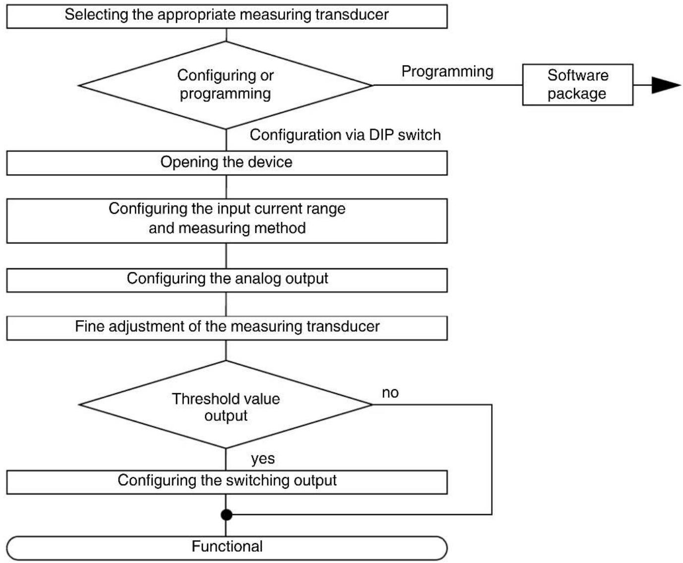
4.3. Functional diagram for configuration
flowchart
graph TD
    A["Selecting the appropriate measuring transducer"] --> B{Configuring or programming}
    B -->|Programming| C["Software package"]
    B -->|Configuration via DIP switch| D["Opening the device"]
    D --> E["Configuring the input current range and measuring method"]
    E --> F["Configuring the analog output"]
    F --> G["Fine adjustment of the measuring transducer"]
    G --> H{Threshold value output}
    H -->|yes| I["Configuring the switching output"]
    I --> J["Functional"]
    H -->|no| K["End"]
4.3.1. Selecting the appropriate measuring transducer
How to select the appropriate measuring transducer can be found in "2.2. Versions" or "7.1. Order Key".

The measured value must always be borne in mind:
0...0.2 A to 0...11 A (MCR-S-1-5-...) or
0...9.5 A to 0...55 A (MCR-S-10-50-...).
If in doubt, always choose the largest possible measuring range.
There is also one version with relay and transistor output for each module type (MCR-S-...-SW-DCI).
4.3.2. Configuring or programming
Using the MCR/PI-CONF-WIN software, the user has the possibility of freely programming the true r.m.s. value current transducer. Programming is described in the software manual. The convenient configuration software runs under all common windows operating systems.
In addition to the programming, modules can be parameterized using DIP switches and potentiometers.
In the rest of this chapter, the configuration is explained:
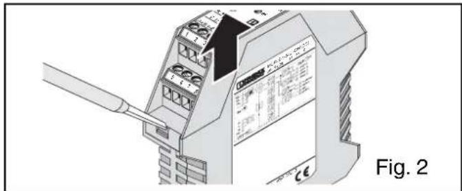
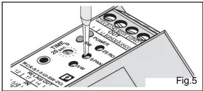
4.3.3. Opening the device

Take protective measures against electrostatic discharge!
Using a screwdriver, the snap lock of the upper part of the housing is unlocked on both sides. The upper part of the housing and the electronics can now be pulled out by approx. 3 cm.
| DIP | Function of the DIP switches |
| 10 | Configuration via DIP switch / Programming via software |
| 9 | Input current measurement: true r.m.s. value / Arithmetic average |
| 8 | Operating/quiescent current behaviour (only threshold value versi- |
| 7 | Threshold value exceeded / Threshold value fallen below (only threshold value version) |
| 6 | Setting the analog output signal |
| 5 | |
| 4 | |
| 3 | |
| 2 | Setting the input measuring range |
| 1 |
Setting DIP switch 10 to configuration mode (DIP switch 10 to "OFF") switches all potentiometers to "active".
| Configuration via: DIP 10 | |
| DIP switch OFF | |
| Software (Any DIP switch (1-9) and potentiometer setting) | ON |
4.3.4. Configuring the input current range and measuring method
(Rough setting via DIP switch)
You have the choice: True r.m.s. value or arithmetic average!
The measuring principle must be preset with DIP switch 9:
| Measuring principle DIP 9 | |
| True r.m.s. value AC and DC without digit sign OFF | |
| Arithmetic average DC with digit sign ON |
True r.m.s. value:
The true r.m.s. value of an AC current corresponds by definition to the permanent value resulting from the momentary values of the current. This permanent value generates the same heat in an ohmic resistor as a DC current of the same strength. True r.m.s. value simply indicates that distorted and pulsating currents are also measured.
Arithmetic average:
The arithmetic average serves to measure DC currents or filter a DC portion from a pulsating current. Using the arithmetic average on a symmetrical AC current would result in a measured value with the value "0".
The arithmetic average makes it possible to make bipolar DC currents available as analog standard signals at the output.
Ideal exploitation of the measuring ranges
| Measuring rangeMCR-S-1-5-...DCI | Spanpotentiometer:-25 % | Nominalrange*:0 % | Spanpotentiometer:+ 25 % | DIP 1 DIP 2 | |
| 1 A input:0...0.2 A to 0...1.1 A | 0...0.75 A | 0...1.00 A | 0... 1.10 A | OFF | OFF |
| 0...0.48 A | 0...0.65 A | 0... 0.81 A | OFF | ON | |
| 0...0.30 A | 0...0.40 A | 0... 0.50 A | ON | OFF | |
| 0...0.18 A | 0...0.25 A | 0... 0.31 A | ON | ON | |
| 5 A input:0...0.94 A to 0...5.5 A | 0...3.75 A | 0...5.00 A | 0... 5.50 A | OFF | OFF |
| 0...2.43 A | 0...3.25 A | 0... 4.06 A | OFF | ON | |
| 0...1.50 A | 0...2.00 A | 0... 2.50 A | ON | OFF | |
| 0...0.94 A | 0...1.25 A | 0... 1.56 A | ON | ON | |
| 10 A input:0...4.87 A to 0...11 A | 0...7.50 A | 0...10.0 A | 0... 11.00 A | OFF | OFF |
| 0...4.87 A | 0 ... 6.5 A | 0 ... 8.12 A | OFF | ON | |
| Measuring rangeMCR-S-10-50-...DCI | Spanpotentiometer:-25 % | Nominalrange*:0 % | Spanpotentiometer:+ 25 % | DIP 1 DIP 2 | |
| 0...9.5 A to 0...55 A | 0...37.5 A | 0...50.0 A | 0... 55.0 A | OFF | OFF |
| 0...24.4 A | 0...32.5 A | 0... 40.6 A | OFF | ON | |
| 0...15.0 A | 0...20.0 A | 0... 25.0 A | ON | OFF | |
| 0...9.38 A | 0...12.5 A | 0... 15.6 A | ON | ON | |
* The nominal range has been adjusted!
4.3.5. Configuring the analog output
| DIP 3 | DIP 4 DIP | 5 DIP 6 | |||
| Output | 0...20 mA | OFF | OFF | OFF | OFF |
| 20... 0 mA | OFF | OFF | OFF | ON | |
| 4...20 mA | OFF | OFF | ON | OFF | |
| 20... 4 mA | OFF | OFF | ON | ON | |
| 0...10 V | OFF | ON | OFF | OFF | |
| 10... 0 V | OFF | ON | OFF | ON | |
| 0... 5 V | OFF | ON | ON | OFF | |
| 5... 0 V | OFF | ON | ON | ON | |
| 1... 5 V | ON | OFF | ON | OFF | |
| 5... 1 V | ON | OFF | ON | ON | |
| -10... 10 V | ON | ON | OFF | OFF | |
| 10...-10 V | ON | ON | OFF | ON | |
| -5... 5 V | ON | ON | ON | OFF | |
| 5... -5 V | ON | ON | ON | ON | |
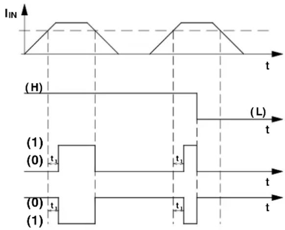
4.3.6. Configuring the threshold value output
The relay and transistor output of the threshold value versions (MCR-S-...-SW-DCI) are set after the input measuring range and the analog output have been adjusted.
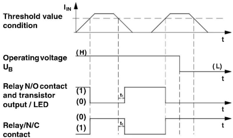
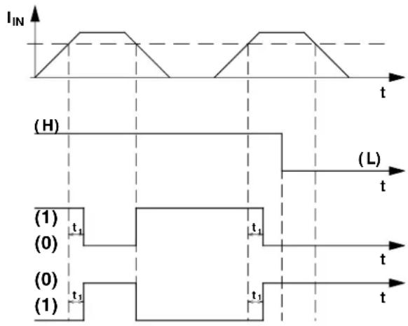
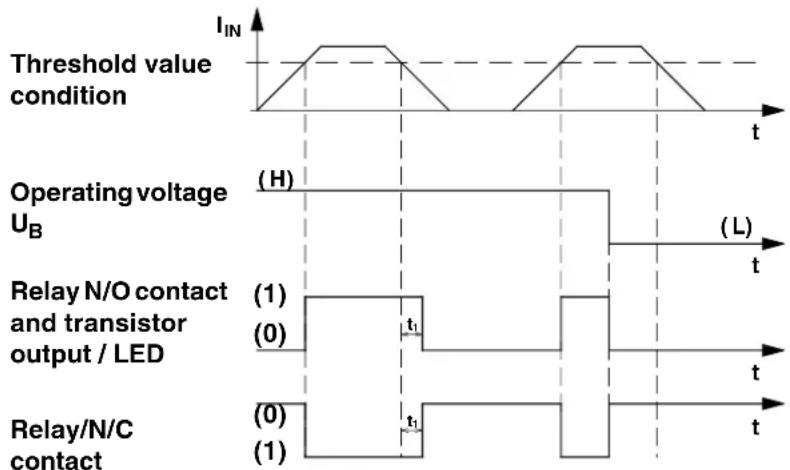
Setting the switching threshold:
The illustration opposite (Fig. 4) shows the four possibilities of switching behavior of the relay and transistor output. The splitting of the various operational behaviors in threshold value operation is carried out on the principle of operating current or quiescent current and after threshold value triggering when below the threshold value point or when it is exceeded.
If necessary, the corresponding switching behaviour can be set via DIP switch 7 and DIP switch 8.
| Functional diagram | Switching behavior of relay and transistor output DIP 7 DIP 8 | ||
| Fig. 1 | Operating current-controlled when threshold value is exceeded | OFF | OFF |
| Fig. 2 | Operating current-controlled when lower than threshold value | ON | OFF |
| Fig. 3 | Quiescent current-controlled when threshold value is exceeded | OFF | ON |
| Fig. 4 | Quiescent current-controlled when below threshold value | ON | ON |
1) Operating current-controlled when threshold value is exceeded
2) Operating current-controlled when below threshold value
line
| Signal Type | Label | | ------------------------------- | ------------------------- | | Threshold value condition | I_IN | | Operating voltage UB | (H) | | Operating voltage UB | (L) | | Relay N/O contact and transistor output / LED | (1) | | Relay N/O contact and transistor output / LED | (0) | | Relay/N/C contact | (0) | | Relay/N/C contact | (1) |3) Quiescent current-controlled when threshold value is exceeded
4) Quiescent current-controlled when below threshold value
other
| Signal Type | Label | | ------------------------------- | ------------------------- | | Threshold value condition | I_IN | | Operating voltage U_B | (H) | | Operating voltage U_B | (L) | | Relay N/O contact and transistor output / LED | (1) | | Relay N/O contact and transistor output / LED | (0) | | Relay N/O contact and transistor output / LED | t₁ | | Relay N/O contact and transistor output / LED | t₂ | | Relay/N/C contact | (0) | | Relay/N/C contact | (1) |(0) ≅ N/O contact and transistor open / N/C contact closed / LED off
(1) ≅ N/O contact and transistor closed / N/C contact open / LED on
t_1 can be set with software and potentiometer.
Fig.4
4.3.7. Fine adjustment of the measuring transducer
After roughly setting the input current range and preselecting the output signal, the module must be closed and connected to the signal lines and operating voltage following chapter 4.1. "Electrical connection".
When the green LED lights up (operating voltage display) this shows that the operating voltage of 20...30 V DC is connected.

ATTENTION:
When using the MCR-S-1-5-...-DCI, please be sure to use the signal input terminal block to suit your measuring range!
| Signal input range | Signal input terminal | Ground terminal block |
| 1 A 7 | 8 | |
| 5 A 6 | 8 | |
| 10 A 5 | 8 |

Please adhere to a warm-up phase for the module of 2 minutes before the adjustment procedure.
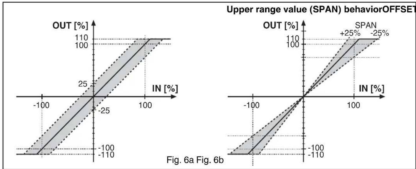
4.3.7.1. Analog output
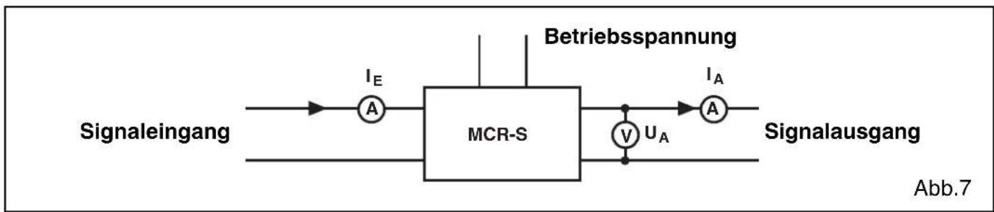
ZERO and SPAN behavior ( ± 25 % each) are shown in the graphic below:
- ZERO potentiometer for zero adjustment.
- SPAN potentiometer for upper range (full scale) value adjustment.
line
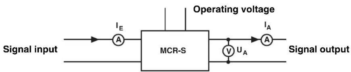
| Panel | X Range | Y Range | Change (%) | |-------|-------------|-------------|------------| | Left Plot | -100 to 100 | -100 to 100 | 25 | | Right Plot | -100 to 100 | -100 to 100 | +25 |Adjustment:
flowchart
graph LR
    A["Signal input"] --> B["A"]
    B --> C["MCR-S"]
    C --> D["V"]
    D --> E["U_A"]
    E --> F["A"]
    F --> G["Operating voltage"]
    G --> H["I_E"]
    H --> I["Signal output"]
Fig.7
- After the operating voltage and the signal lines have been connected, zero or offset must first be adjusted. No signal may be present at input ( I_i = 0 ).
- The analog output must correspond to a preselected output signal from table 6.3.5. Any inaccuracy can be adjusted with the ZERO potentiometer.
- To adjust the measuring upper range (full scale) value, a current of preferably the strength of the upper range value should be given. If this is not possible, one of the following adjustment equations should be used:
Example: The current transducer is to be set to the following values:
Input measuring range: 0...5 A I
$$ \mathrm{MI} = 5 \mathrm{A} $$
Output measuring range: 0...20 mA I
$$ 0 = 0 \mathrm{mA} \mid_ {\mathrm{MO}} = 2 0 \mathrm{mA} $$
Constant current for configuration I
$$ _ 1 = 3 \mathrm{A} $$
$$ \boxed { \begin{array}{c} I _ {A} = I _ {0} + (\frac {I _ {E}}{I _ {M E}} * (I _ {M A} - I _ {0})) \ U _ {A} = U _ {0} + (\frac {I _ {E}}{I _ {M E}} * (U _ {M A} - U _ {0})) \end{array} } $$
The output current calculated must be adjusted with the SPAN potentiometer to I_O = 12 mA.
When the voltage output is used, the same adjustment procedure is necessary.
4.3.7.2. Threshold value output
A current that corresponds to the threshold value is to be given for the module.
The TIME potentiometer must be set to "0 s" and the threshold value (SW) potentiometer is to be turned according to the following adjustment ruling (following Fig 4, page 22):
- Fig. 1: The threshold value (SW) potentiometer must be turned until the SW-LED lights up.
- Fig. 2: The threshold value (SW) potentiometer must be turned until the SW-LED goes off.
- Fig. 3: The threshold value (SW) potentiometer must be turned until the SW-LED goes off.
- Fig. 4: The threshold value (SW) potentiometer must be turned until the SW-LED lights up.
In order to avoid switching actions at the binary output level during a brief overload, a suppression time must be set with the TIME potentiometer. If an increased current is present for longer than the given suppression time, the preselected switching behavior becomes active. The possible adjustment range is between 0 and 20 seconds.
When the yellow threshold value (SW) LED lights up (relay and transistor status display) the N/O contact of the PDT contact is closed and the N/C contact of the PDT contact is open. The transistor output switches through.
4.4. Software package (adapter)
As an alternative to setting via DIP switch, programming is possible using MCR/PI-CONF-WIN, the configuration software (Order No. 2814799).
The software offers the following:
- Entering all the configuration parameters in the computer
- Saving the parameters entered in the computer in the measuring transducer
- Exporting the parameters available from the module
- Saving parameters in a drive of your choice
- Creating a side-panel label
- Printing the programmed module parameters
- Bar graph display
• Monitoring function - Input of user characteristic curves possible
The software runs under Windows 95 ^TM , 98 ^TM , ME ^TM , NT ^TM , 2000 ^TM and XP ^TM .

Interface converter MCR-TTL/RS232-E (Order No. 2814388) serves to connect the computer and the current measuring transducer. This converter has a stereo jack plug on one side for connection to the current measuring transducer and a 25-pos. SUB-D socket on the other side for connection to a computer. On the computer side, the interface converter must generally be connected with a cable adapter (25 to 9-pos. SUB-D plug connection, Order No. 2761295).
5. Sample applications
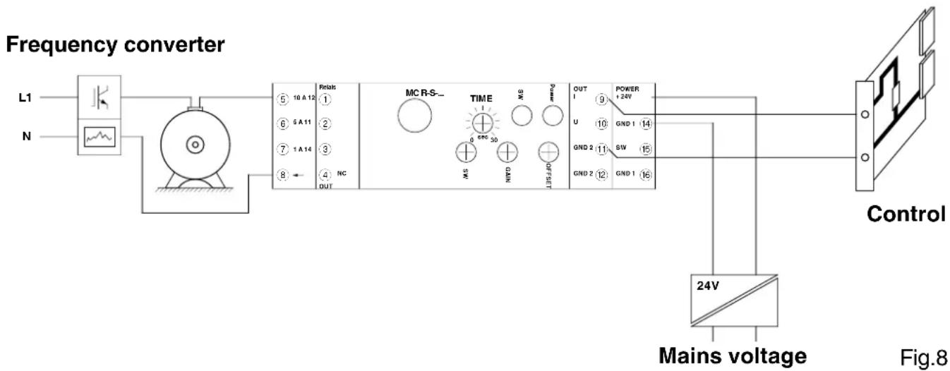
5.1. Measurement of motor currents
By using MCR-S modules in one or more input phases of the motor, so-called motor monitoring can be carried out (Fig.8).
The MCR current measuring transducer can pass on corresponding standard signals about motor load to the controller or service personnel.
The true r.m.s. measurement means that AC, DC and distorted currents can be measured. Even higher frequency currents up to 400 Hz can be measured.
flowchart
graph LR
    A["Power Supply L1"] --> B["Frequency Converter"]
    C["N"] --> B
    B --> D["Control Unit"]
    D --> E["24V Mains voltage"]
    E --> F["Mains voltage"]
    B --> G["Relais 10A 12 NC OUT"]
    B --> H["MC R-S- TIME 89C 30 SW 0 6NC 50 0 0 0 0 0 0 0 0 0 0 0 0 0 0 0"]
    H --> I["OUT 1 9 +24V U GND 1 GND 2 GND 2 GND 1 GND 1 GND 1 GND 1 GND 1 GND 1 GND 1 GND 1 GND 1 GND 1 GND 1 GND 1 GND 1 GND 1 GND 1 GND 1 GND 1 GND 1 GND 1 GND 1 GND 1 GND 1 GND 1 GND 1 GND 1 GND 2 GND 2 GND 2 GND 2 GND 2 GND 2 GND 2 GND 2 GND 2 GND 2 GND 2 GND 2 GND 2 GND 2 GND 2 GND 2 GND 2 GND 2 GND 2 GND 2 GND 2 GND 2 GND 2 GND 2 GND 2 GND 3 GND 3 GND 3 GND 3 GND 3 GND 3 GND 3 GND 3 GND 3 GND 3 GND 3 GND 3 GND 3 GND 3 GND 3 GND 3 GND 3 GND 3 GND 3 GND 3 GND 3 GND"]
    style B fill:#f9f,stroke:#333
    style D fill:#ccf,stroke:#333
    style E fill:#cfc,stroke:#333
    style F fill:#fcc,stroke:#333
    style B fill:#ffc,stroke:#333
    style D fill:#fcc,stroke:#333
    style E fill:#ffc,stroke:#333
    style B fill:#fff,stroke:#333
    style D fill:#fff,stroke:#333
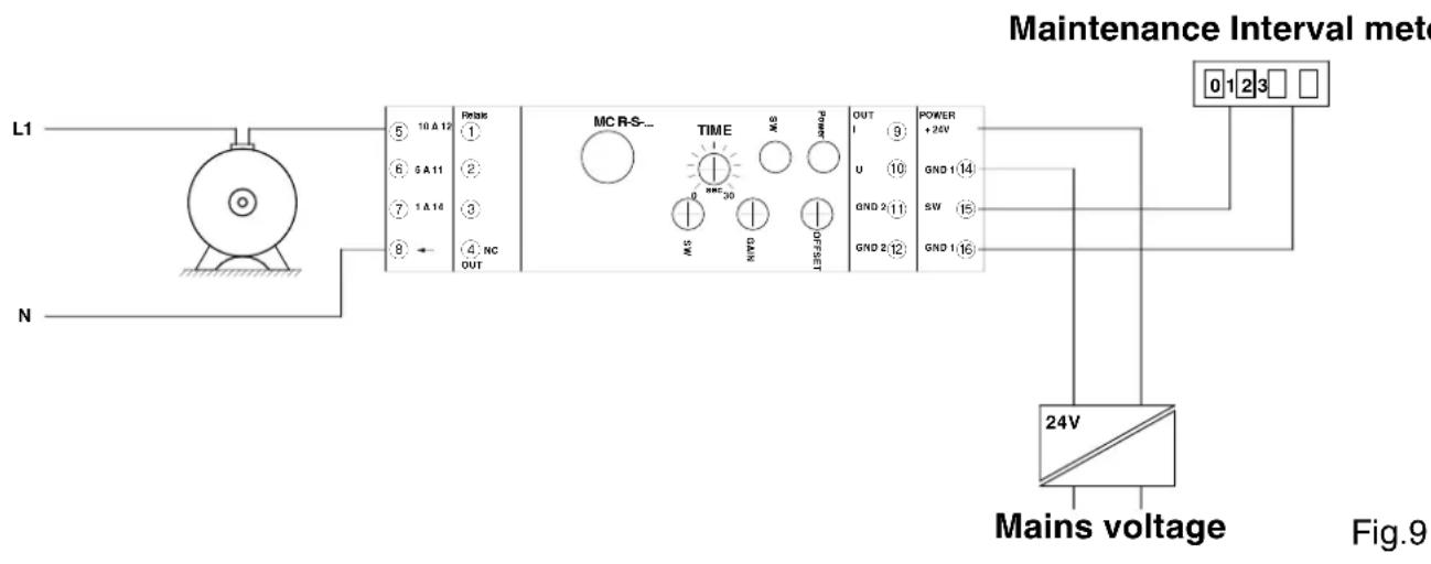
5.2. Recording motor current peak loads
Large industrial motors have to be overhauled and serviced at regular intervals.
Installing an MCR current transducer in one phase of the motor feed line allows impulses to be generated with the relay or transistor switching output that can be measured with the aid of a simple meter (Fig.9). The service personnel can provide efficient maintenance on the basis of the motor starts and peak loads corresponding to the number of overloads.
flowchart
graph TD
    A["Main Voltage"] --> B["24V"]
    B --> C["Mains voltage"]
    D["L1"] --> E["Motor"]
    F["N"] --> G["Ground"]
    H["Maintenance Interval meter"] --> I["0 1 2 3"]
    J["Power + 24V"] --> K["GND 1 14"]
    L["OUT"] --> M["GND 2 11"]
    N["TIME"] --> O["SW"]
    P["OUT"] --> Q["SW"]
    R["TIME"] --> S["SW"]
    T["OUT"] --> U["SW"]
    V["TIME"] --> W["SW"]
    X["OUT"] --> Y["SW"]
    Z["TIME"] --> AA["SW"]
    AB["OUT"] --> AC["SW"]
    AD["TIME"] --> AE["SW"]
    AF["OUT"] --> AG["SW"]
    AH["TIME"] --> AI["SW"]
    AJ["OUT"] --> AK["SW"]
    AL["TIME"] --> AM["SW"]
    AN["OUT"] --> AO["SW"]
    AP["Mains voltage"] --> AQ["24V"]
5.3. Monitoring lighting
MCR current transducers can be used for monitoring lighting.
If the strength of the current in circuit is exceeded or fallen below after a suppressed turn-on time, there is a defect in the lighting circuit. If the lighting circuit fails, this signal status can be passed on to another control unit and the emergency lighting can be switched on. The same procedure can also be used with other consumers.
- Technical data
| Type / Order No. MCR-S-1-5-UI-... MCR-S-10-50-UI-... | ||
| MCR-S-...-UI-DCI | 2814634 | 2814647 |
| MCR-S-...-UI-DCI-NC | 2814715 | 2814728 |
| MCR-S-...-UI-SW-DCI | 2814650 | 2814663 |
| MCR-S-...-UI-SW-DCI-NC | 2814731 | 2814744 |
| Measurement input | ||
| Input current (AC, DC or distorted currents) | 0...0.2 A to 0...11 A | 0...9.5 A to 0...55 A |
| Frequency range for periodic quantities | 15 Hz ... 400 Hz | 15 Hz ... 400 Hz |
| Type of connection Screw terminal block | 2.5 mm^2 | Through connection 10.5 mm |
| Overload capacity, continuous 2 x l | nom | depending on conductor pushed through |
| Overload capacity for 1 s 20 x l | nom | |
| Output | ||
| Output current / Load 0(4)...20 mA / < 500 Ω | ||
| Output voltage / Load | 0(2)...10 V / > 10 kΩ0(1)...5 V / > 10 kΩ±10 V, ±5 V / > 10 kΩ | |
| Switching output only ...SW-... version: | ||
| Relay output 1 PDT | ||
| Contact material | AgSnO, hard gold-plated | |
| Max. switching voltage | 30 V AC/36 V DC ^1) | |
| Cont. current carrying capacity | 50 mA ^1) | |
| Transistor output | PNP output | |
| Max. transistor current | 80 mA | |
| Output voltage at time of event | 1 V below supply voltage | |
| Threshold value setting | 1 % to 110 % | |
| Suppression time | 0.1 ... 20 s | |
| Status display | yellow LED | |
| General data | MCR-S-1-5-UI-... | MCR-S-10-50-UI-... |
| Supply voltage | 20 ... 30 V DC | 20 ... 30 V DC |
| Current consumption (without load) | Approx. 40 mA (SW version: approx. 50 mA ) | |
| Transmission error of range nom. value under nominal conditions: | < 0.5 % | < 0.5 % |
| Measuring range nom. value | 0...1 A / 5 A / 10 A | 0...50 A |
| Response threshold of measuring range nom. value | 2 % | 0.8 % |
| Input signal form | 50 Hz sinus | 50 Hz sinus |
| Method of measurement | True r.m.s. value | True r.m.s. value |
| Ambient temperature | 23 °C | 23 °C |
| Supply voltage | 24 V DC | 24 V DC |
| Temperature coefficient | typ. 0.025 %/K | typ. 0.025 %/K |
| Measuring rate | AC 5 measurements / s | 5 measurements / s |
| DC 40 measurements / s | 40 measurements / s | |
- Technical data
| Reliable isolation• I/O (Analog), I/O (Relay) 2),I/O (Transistor), I/S | acc. to EN 50178, EN 61010:300 V AC to earth 3) |
| Test voltage:• I/O (Analog), I/O (Relay), I/O (Transistor), I/S• O (Analog)/O (Relay), O (Relay)/O (Transistor)• O(Analog)/O(Transistor), O (Analog)/S | 4 kV, 50 Hz, 1 min.4 kV, 50 Hz, 1 min.500 V, 50 Hz, 1 min. |
| Surge voltage category III | |
| Contamination class 2 | |
| Ambient temperature range operation storage | -20 °C to +60 °C-40 °C to +85 °C |
| Module warm-up time >2 min. | |
| Function standby signal green LED | |
| Protection type IP 20 | |
| Installation position/mounting any | |
| Dimensions (W / H / D) in mm 22.5 x 99 x 114.5 | |
| Conductor cross section 0.2 – 2.5 mm | 2 (AWG 24-14) |
| Type of housing polyamide PA non-reinforced |
1) If the maximum values indicated are exceeded, the gold layer is destroyed! The following max. switching voltages and currents are then valid for further operation: 250 V AC/DC; 2A.
2) I ≅ Input / O ≅ Output / S ≅ Supply
3) Suitable for measuring in 400 V AC three-phase system.
Conformity / approvals (€
| Conformance | with low voltage directive | 2006/95/EC |
| Conformance | with EMC directive | 2004/108/EC |
| Immunity to interference | according to | EN 61000-6-2 |
| Noise emission | according to | EN 61000-6-4 |
UL approval

PROCESS CONTROL EQUIPMENT FOR HAZARDOUS LOCATIONS
LISTED 31ZN
Cl. I, Zn. 2, AEx nC IIC T6 / Ex nC IIC T6
Cl. I Div. 2, Groups A, B, C and D or Non-Hazardous Locations Only
A) This equipment is suitable for use in Class I, Division 2, Groups A, B, C and D or non-hazardous locations only.
B) Warning - explosion hazard - substitution of components may impair suitability for Class 1, Division 2,/Zone 2.
C) Warning - explosion hazard - do not disconnect equipment unless power has been switched off or the area is known to be non-hazardous.
flowchart
graph TD
    A["10A"] --> B["⑤"]
    C["5A"] --> D["⑥"]
    E["1A"] --> F["⑦"]
    G["⑧"] --> H["Ⅱ"]
    I["IN"] --> J["→"]
    K["SET"] --> L["△"]
    M["OUT"] --> N["←"]
    style K stroke-dasharray: 5 5
    style L stroke-dasharray: 5 5
    style M stroke-dasharray: 5 5
    style N stroke-dasharray: 5 5
MCR-S-1-5-...
flowchart
graph TD
    IN --> A["Inverter"]
    A --> B["×"]
    B --> C["ADC/μC"]
    C --> D["DAC/I"]
    D --> E["OUT"]
    C --> F["DAC/U"]
    F --> G["9 OUT I"]
    F --> H["10 OUT U"]
    F --> I["11 GND 2"]
    F --> J["12 GND 2"]
    C --> K["SPAN"]
    K --> L["ZERO"]
    L --> M["TIME POINT"]
    M --> N["SET"]
    N --> O["OUT"]
    style A fill:#f9f,stroke:#333
    style B fill:#ccf,stroke:#333
    style C fill:#cfc,stroke:#333
    style D fill:#fcc,stroke:#333
    style E fill:#cff,stroke:#333
    style F fill:#ffc,stroke:#333
    style G fill:#fcc,stroke:#333
    style H fill:#fcc,stroke:#333
    style I fill:#fcc,stroke:#333
    style J fill:#fcc,stroke:#333
    style K fill:#ffc,stroke:#333
    style L fill:#ffc,stroke:#333
    style M fill:#ffc,stroke:#333
    style N fill:#ffc,stroke:#333
    style O fill:#fff,stroke:#333
MCR-S-10-50-...
line
| Chart | X Range | Y Range | Change (%) | |-------|-------------|-------------|------------| | Left Plot | -100 to 100 | -100 to 100 | 110 | | Right Plot | -100 to 100 | -100 to 100 | +25 |Cl. I Div. 2, Groups A, B, C and D or Non-Hazardous Locations Only
Cl. I Div. 2, Groups A, B, C and D or Non-Hazardous Locations Only
Cl. I Div. 2, Groups A, B, C and D or Non-Hazardous Locations Only