FPM 23.8 69K - Monitor Phoenix Contact - Free user manual and instructions
Find the device manual for free FPM 23.8 69K Phoenix Contact in PDF.

| Product Type | Industrial Monitor |
| Brand | Phoenix Contact |
| Model | FPM 23.8 69K |
| Display Size | 23.8 inches (diagonal) |
| Resolution | 1920 x 1080 pixels (Full HD) |
| Aspect Ratio | 16:9 |
| Brightness | 250 cd/m² (typical) |
| Contrast Ratio | 1000:1 (typical) |
| Viewing Angle | 178° horizontal / 178° vertical |
| Touchscreen | Not specified (likely optional) |
| Input Interfaces | HDMI, DisplayPort, VGA |
| Power Supply | AC 100-240V, 50/60 Hz |
| Power Consumption | ≤ 25 W (typical) |
| Dimensions (W x H x D) | Approx. 550 x 330 x 60 mm (without stand) |
| Weight | Approx. 5.5 kg (with stand) |
| VESA Mount | 100 x 100 mm |
| Operating Temperature | 0°C to 40°C |
| Certifications | CE, FCC, UL |
| Included Accessories | Power cable, HDMI cable, user manual |
Frequently Asked Questions - FPM 23.8 69K Phoenix Contact
User questions about FPM 23.8 69K Phoenix Contact
0 question about this device. Answer the ones you know or ask your own.
Ask a new question about this device
Download the instructions for your Monitor in PDF format for free! Find your manual FPM 23.8 69K - Phoenix Contact and take your electronic device back in hand. On this page are published all the documents necessary for the use of your device. FPM 23.8 69K by Phoenix Contact.
USER MANUAL FPM 23.8 69K Phoenix Contact
natural_image
Black rectangular electronic device with blank screen, isolated on light blue background (no text or symbols)Installing and operating the 17" and 24" hygiene monitors / panel PCs
User manual
User manual
Installing and operating the 17" and 24" hygiene monitors / panel PCs
UM EN FPM/PPC 17.3/23.8 (AIO) 69K (SP), Revision 01
2024-10-17
This user manual is valid for:
Designation Order No.
| FPM 17.3 69K SP | 1261656 |
| FPM 17.3 69K | 1261657 |
| FPM 23.8 69K | 1261659 |
| FPM 23.8 69K SP | 1261662 |
| PPC 17.3 AIO 69K | 1262469 |
| PPC 23.8 AIO 69K | 1262470 |
Table of contents
1 For your safety 5
1.1 Identification of warning notes .... 5
1.2 Qualification of users....5
1.3 Field of application of the product.... 5
1.3.1 Intended use 5
1.3.2 Improper use 6
1.3.3 Product changes 6
1.4 Safety notes 6
1.4.1 Ambient conditions 7
1.4.2 Damage due to improper use 7
1.4.3 Components sensitive to electrostatic discharge 8
1.5 Security in the network 8
1.6 Applied directives and standards....9
2 Transport, storage, and unpacking 11
2.1 Transport....11
2.2 Storage....11
2.3 Unpacking....11
3 Product description 13
4 Mounting the hardware 15
4.1 Pre-assembly of the connection tube 15
4.1.1 Support arm mounting 15
4.1.2 Stand mounting 16
4.2 Dimensions of the mounting versions.... 17
4.3 Mounting with VESA adapter.... 19
4.4 Mounting with tube adapter 22
5 Connecting and wiring the hardware 23
5.1 Interfaces of the monitors 23
5.2 Interfaces of the panel PCs.... 24
5.3 Supply voltage....25
5.4 DisplayPort 26
5.5 HDMI 26
5.6 USB 26
5.6.1 Cables 26
5.7 Ethernet....26
5.8 Mass storage....27
5.9 Grounding....27
5.9.1 Basic information on grounding 27
5.9.2 Grounding of PPC xxxx panel PCs 28
5.9.3 Grounding of FPM xxxx monitors 28
6 Startup 29
6.1 Checking for operational readiness 29
6.2 Starting up the device.... 30
7 Operating the device ....31
7.1 Switching on and off 31
7.2 Touchscreen 31
7.3 WLAN and Bluetooth.... 31
8 Component replacement, device defect, and repairs ....33
8.1 Component replacement.... 33
8.1.1 Battery replacement 33
8.1.2 Replacing the mass storage 35
8.2 Device defect and repair.... 36
9 Maintenance, decommissioning, and disposal ....37
9.1 Maintenance....37
9.2 Cleaning 37
9.2.1 Cleaning agents and disinfectants 37
9.3 Decommissioning and disposal.... 38
10 Technical data and ordering data ....39
10.1 Technical data....39
10.2 Ordering data 41
A Appendix for document lists....43
A 1 List of figures ...... 43
A 2 List of tables ....45
A 3 Index....47
1 For your safety
Read this user manual carefully and keep it for future reference.
1.1 Identification of warning notes

This symbol indicates hazards that could lead to personal injury.
There are three signal words indicating the severity of a potential injury.
DANGER
Indicates a hazard with a high risk level. If this hazardous situation is not avoided, it will result in death or serious injury.
WARNING
Indicates a hazard with a medium risk level. If this hazardous situation is not avoided, it could result in death or serious injury.
CAUTION
Indicates a hazard with a low risk level. If this hazardous situation is not avoided, it could result in minor or moderate injury.

This symbol together with the NOTE signal word warns the reader of actions that might cause property damage or a malfunction.

Here you will find additional information or detailed sources of information.
1.2 Qualification of users
The use of products described in this user manual is oriented exclusively to electrically skilled persons or persons instructed by them. The users must be familiar with the relevant safety concepts of automation technology as well as applicable standards and other regulations.
1.3 Field of application of the product
1.3.1 Intended use
The operating system is designed for use in the pharmaceutical, food, beverage, and chemical industries. It has been specifically developed for areas with strict hygiene requirements. The device is used to visualize and control a wide range of processes on systems and machines in different application environments.
The device may only be mounted, installed, and operated in accordance with the approved specifications. Use under ambient conditions other than those specified in these instructions is prohibited.
1.3.2 Improper use
Any operation of the device contrary to or above and beyond the operation described in this manual constitutes improper use.
The device may not be used to steer vehicles or for applications that require approvals that exceed the manufacturer's declaration (e.g., Ex area, medical technology, or maritime use).
Likewise, the device may not be started up if damaged during transport or if it does not comply with the specifications, and it must be taken out of operation if conditions change.
Phoenix Contact accepts no responsibility and no liability for personal injury or property damage, whether indirect or direct, resulting from improper use of the device.
1.3.3 Product changes
Modifications to hardware and firmware of the device are not permitted.
Incorrect operation or modifications to the device can endanger your safety or damage the device. Do not repair the device yourself. If the device is defective, please contact Phoenix Contact.
1.4 Safety notes
- All users must read this user manual and it must be available at all times.
- The safety notes and user manual must be observed by all persons working with the device.
- The user manual contains important information for operating the device safely.
- User intervention is only permitted to perform the processes described in this document. In the event more far-reaching changes are being made, consult the manufacturer or an authorized service center.
- The device must be disconnected from the power supply when work is being performed. Appropriate measures must be taken to prevent electrostatic discharge to components.
- Allowing the device to be opened by unauthorized personnel may be hazardous to the user and will render any claims under warranty invalid.
- Mounting, startup, and operation may only be carried out by skilled and trained personnel.
- The applicable rules and regulations governing accident prevention must be observed at the installation location of the device.
– In order to ensure the safe and correct operation of the device, appropriate storage, transport, installation, and startup as well as careful operation are required. - The device can be cleaned with the cleaning agents listed in Section 9.
1.4.1 Ambient conditions

NOTE: Heat damage
Exposing the device to direct sunlight or other sources of light or heat can cause it to overheat and damage it.
- Do not expose the device to direct sunlight or other sources of light or heat.
Installing the device in a console, enclosure, or similar environment can cause heat to build up. - Make sure that heat can be drawn away from the device.

NOTE: Condensation damage
Condensation may form if the device temperature is different from that of the room.
- Do not switch the device on until its temperature has equalized to the room temperature.
Use is only permitted:
- In enclosed buildings
- In non-Ex areas
- At a height below 2000 m
– In environments with maximum pollution degree 2 (IEC/EN 61131-2)
The device may be operated under the ambient conditions (temperature, humidity, vibration, and shock) indicated in the technical data (see Section "Technical data and ordering data" on page 39). Failure to comply with these conditions will void the device warranty. Phoenix Contact is not responsible for damage due to improper handling.
The climatic conditions have been tested in accordance with:
- IEC/EN 60068-2-1
- IEC/EN 60068-2-2
- IEC/EN 60068-2-14
- IP69K degree of protection in accordance with DIN EN 60529/ISO 20653
1.4.2 Damage due to improper use

NOTE: Danger due to mechanical damage
Making mechanical alterations to the device that are not permitted may damage it.
- Make sure that the device is not drilled into, chiseled, punched, or its exterior altered in any other way.
If the operating system shows obvious signs of damage caused, for example, by transport, failure to comply with the specifications, inappropriate operating and storage conditions, or improper handling, the device must be stopped immediately and protected against unintentional startup.
1.4.3 Components sensitive to electrostatic discharge

NOTE: Damage due to components that are sensitive to electrostatic discharge Electrostatic discharge can damage the device.
- Only carry out mounting and servicing work on the device when it is in a safe state and disconnected from the power supply.

Observe the relevant safety measures in accordance with DIN EN 61340-5-1/2 when handling components that are sensitive to electrostatic discharge.
1.5 Security in the network

NOTE: Risk of unauthorized network access
Connecting devices to a network via Ethernet entails the risk of unauthorized access to the network.
Therefore, please check for the option of disabling active communication channels in your application (for instance SNMP, FTP, BootP, DCP, HTTP, HTTPS, etc.) or setting passwords to prevent third parties from accessing the device without authorization and modifying the system.
Due to its communication interfaces, the device should not be used in safety-critical applications unless additional security appliances are used.
Please take additional precautions in accordance with the IT security requirements and standards applicable to your application (e.g., virtual networks (VPN) for remote maintenance access, firewalls, etc.) to prevent unauthorized network access.
On first request, you shall release Phoenix Contact and the companies associated with Phoenix Contact GmbH & Co. KG, Flachsmarktstrasse 8, 32825 Blomberg, Germany in accordance with §§15ff. AktG (German Stock Corporation Act), hereinafter collectively referred to as "Phoenix Contact", from all third-party claims made due to improper use.
For the protection of networks for remote maintenance via VPN, Phoenix Contact offers security appliances in the mGuard product series. Further information on mGuard is available in the latest Phoenix Contact catalog (phoenixcontact.net/products).
Additional measures for protection against unauthorized network access are listed in the AH EN INDUSTRIAL SECURITY application note. The application note can be downloaded at phoenixcontact.net/product/1262469.
1.6 Applied directives and standards
The manufacturer hereby declares that the product described in these instructions complies with all of the applicable provisions of the following European directives:
- 2011/65/EU, RoHS Directive
- 2014/30/EU, EMC Directive
- 2014/53/EU, RED Directive
- 2014/35/EU, Low Voltage Directive
The product is a Class A item of equipment (for industrial environments).

In order to comply with the statutory requirements regarding EMC, the connected components and the cable connections must also satisfy these requirements. Shielded bus and LAN cables with shielded connectors must therefore be used and installed in accordance with the stipulations provided in these operating instructions.
The EU declaration of conformity can be downloaded in the Download area on our website.
The versions bearing the UL symbol on the device label also conform to the following UL standards:
- UL 61010-1 Programmable Controllers
- UL 61010-2-201 UL File Number E343358
- CAN/CSA-C22.2 No. 61010-1
- CAN/CSA-C22.2 No. 61010-2-201
2 Transport, storage, and unpacking
2.1 Transport
The device is delivered in cardboard packaging.
- Observe the handling instructions on the packaging.
Suitable transport packaging
- Only transport the device in its original packaging or in packaging suitable for transport.
Technical data and environmental conditions
- For storage, observe the humidity and air pressure specifications, and the temperature range.
i See Section "Technical data and ordering data" on page 39.
2.2 Storage
Suitable storage location The storage location must meet the following requirements:
- Dry
- Protected from unauthorized access
- Protected from harmful environmental influences such as UV light
Technical data and environmental conditions
- For storage, observe the humidity and air pressure specifications, and the temperature range.
i See Section "Technical data and ordering data" on page 39.
2.3 Unpacking

NOTE: Damage to components containing soft parts
If the soft material is subjected to a concentrated load, e.g., by placing it on a grating, irreversible impressions will form after some time.
- Make sure that a suitable surface is provided when setting down the device on its display side, e.g., a clean, flat surface.
The device is delivered in packaging together with a packing slip that provides installation instructions.
Observing the packing slip
- Read the complete packing slip carefully before unpacking the device.
- Retain the packing slip.
Checking the delivery • Check the delivery for damage and completeness.
- Submit claims for any transport damage immediately.
Scope of supply The standard scope of supply for the product is as follows:
- Monitor/panel PC
- 3-pos. connector (monitor, FPM xxxx) / 4-pos. connector (panel PC, PPC xxxx) for the power supply
-
Packing slip
-
Drilling template (for support arm adapter)
– M3 Allen key as an installation aid
3 Product description
The monitors (FPM xxxx) and panel PCs (PPC xxxx) are designed for the control and visualization of production processes in the pharmaceutical, food, beverage, and chemical industries. In the case of the panel PCs, the processing unit is integrated in the housing, so an external PC is not required for control. The monitor is a display which can be controlled by an external computer, e.g., from the existing industrial computer environment. With the monitor, cables can be used for distances of up to 10 m between the display and computer. Panel PCs and monitors are both available in 17 and 24 inch format.
The devices have been specifically developed to satisfy strict hygiene requirements. This is achieved by the stainless steel housing of the device being completely closed, having rounded edges and no external screws. This allows the device to be cleaned easily and effectively. The device has no fan, which means that the primary source of contamination is not present. Due to its robust, compact design, the device can also be operated under demanding environmental conditions. All necessary cables are routed to the device through the connection tube so that there are no exposed cables in the room. Thanks to the very latest multi-touch technology, the full HD display with a maximum resolution of 1920 x 1080 pixels can be operated conveniently by touching and also by means of swiping and dragging movements. Operation with special gloves is also possible.

natural_image
Two views of a metallic security camera module showing front and side views with mounting holes (no text or symbols visible)Figure 3-1 Versions with tube adapter/VESA adapter
4 Mounting the hardware

NOTE: Damage caused by heat
Exposing the device to direct sunlight or other sources of light or heat can cause it to overheat and damage it.
- Do not expose the device to direct sunlight or other sources of light or heat.

At least two people are needed to assemble the device at the installation location.
Prior to assembly, ensure that all mechanical connections are secure in the connection tube system that you are using.
For installation on your connection system, a VESA adapter or a tube adapter can be mounted on the device. The VESA or tube adapter must be ordered separately.
i See Section "Ordering data" on page 41.
You need the following tools for mounting:
Device mounting – Wrench, 8 mm
Connection tube mounting
- ≥ M6 drill bit, with 120° drill tip
4.1 Pre-assembly of the connection tube

WARNING: Risk of injury
If the connection tube is too thin, the device can work loose in the support arm position and fall to the ground.
- Make sure that the connection tube meets the specifications.
The connection tube must have a diameter of 48.3 mm with a maximum tolerance of ±0.3 mm.
4.1.1 Support arm mounting
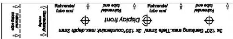
- Attach the self-adhesive mounting template to the end of the connection tube.

The "Display front" marking must be on the side on which the display will later be.
- The arrows must point to the end of the connection tube.
- Attach the template to the connection tube as far as the "Overlap" marking.
- Fold over the template at the "Folding edge" marking so that the end sticks to the back of the "Overlap" area.

text_image
3x 120° Senkung max.Tiefe 2mm/ 3x 120°countersink max.depth 2mm Rohrende/tube end pue eqn performer Display front Rohrende/tube end pue eqn performer Obstellung/overlap Followers/molding edgeFigure 4-1 Template for support arm mounting

Use at least an M6 drill bit with 120° drill tip.
- Countersink the connection tube at the three marked positions to a maximum depth of 2 mm.
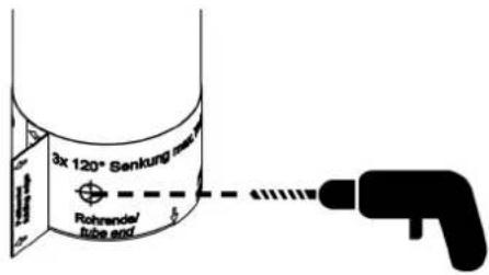
text_image
3x 120° Senkung mass Rohrande/ tube andFigure 4-2 Countersinking the connection tube
- Remove the template.
4.1.2 Stand mounting
- Attach the self-adhesive mounting template to the end of the connection tube.

The "Display front" marking must be opposite the side on which the display will later be.
- The arrows must point to the end of the connection tube.
- Attach the template to the connection tube as far as the "Overlap" marking.
- Fold over the template at the "Folding edge" marking so that the end sticks to the back of the "Overlap" area.
text_image
3x 120° Serkung max-Tierra 2mm 3x 120° Counterink max depth 2mm Display Front Rohrenda/lebra and Rohrenda/lebra and Rohrenda/lebra and Rohrenda/lebra and Rohrenda/lebra and Rohrenda/lebra and Rohrenda/lebra and Rohrenda/lebra and Rohrenda/lebra and Rohrenda/lebra and Rohrenda/lebra and Rohrenda/lebra andFigure 4-3 Template for connection tube mounting

Use at least an M6 drill bit with 120° drill tip.
- Countersink the connection tube at the three marked positions to a maximum depth of 2 mm.
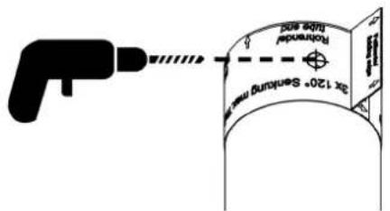
text_image
2x 120° Sensing unit Forward Duo unitFigure 4-4 Countersinking the connection tube
- Remove the template.
4.2 Dimensions of the mounting versions
The device dimensions correspond to those specified in the "Technical data and ordering data". However, the depth differs depending on the mounting version.
For the version with service slot cover (right), the depth essentially depends on the design of the customer's VESA mount.

natural_image
Technical illustration of a metallic mechanical component with two views (labeled 1 and 2), showing no text or symbols.Figure 4-5 Side view with tube adapter/service slot cover
1 17" device: 160 mm 24" device: 250 mm
2 17" device: 83 mm
24" device: 84 mm
4.3 Mounting with VESA adapter
Removing the cloverleaf seals
- Make sure that the device and all cables are disconnected from the power supply.
Proceed as follows to feed the cables through the cloverleaf seals:
- Remove the six screws (red marking in Figure 4-10) and seals (Figure 4-6), and pull the service slot cover off the housing.

natural_image
Mechanical assembly diagram showing a housing with bolts and shafts, no text or symbols presentFigure 4-6 Removing the service slot cover
- Loosen the screws (blue marking in Figure 4-7) of the cloverleaf holders (green marking in Figure 4-7) and remove the cloverleaf seals (see Figure 4-8).

Be careful not to lose the retaining washers (red marking in Figure 4-7).

natural_image
Mechanical assembly diagram showing internal components with no visible text or symbolsFigure 4-7 Loosening the screws of the cloverleaf holders

natural_image
Mechanical assembly diagram showing a black housing connected to a coiled spring and a cylindrical component (no text or symbols visible)Figure 4-8 Removing the cloverleaf seals
- Make all connections (see Section "Connecting and wiring the hardware" on page 23) and feed the cables through the cloverleaf seals.

NOTE: Damage caused by humidity
To ensure the degree of protection specified in the technical data, observe the permissible cable cross-section for the cloverleaf seals.
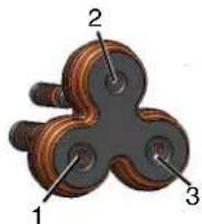
Figure 4-9 Cable cross-section for cloverleaf seals
14-6mm²
2 2.5 - 4 mm²
34-6mm²
Installing the cloverleaf seals

Assembly is done in reverse order with a torque of 3.5 Nm.
Be careful not to lose the retaining washers (red marking in Figure 4-7).
Mounting the VESA adapter
- Screw the VESA adapter onto the device using an 8 mm wrench and a torque of 3.5 Nm.

natural_image
3D rendering of a black plastic electronic component with multiple circular pins and mounting holes (no text or symbols)Figure 4-10 Mounting the VESA adapter on the device
- Mount the device with the VESA adapter onto your connection system (M6, VESA 75).

natural_image
3D rendering of a black plastic electronic component with four circular ports and four mounting holes (no text or symbols)Figure 4-11 Mounting the VESA adapter on the connection system
4.4 Mounting with tube adapter
- Make sure that the device and all cables are disconnected from the power supply.
- Route the cables through the adapter.
- Connect all cables to the interfaces in the service slot.
- Screw the tube adapter onto the device using an 8 mm wrench and a torque of 3.5 Nm.

natural_image
3D CAD model of a mechanical bracket assembly with mounting holes and fasteners (no text or symbols visible)Figure 4-12 Position of the seal and screw connection for the tube adapter
- Mount the adapter onto your connection system using an 8 mm wrench and a torque of 3.5 Nm.
5 Connecting and wiring the hardware

NOTE: Damage to the electronics
The electronics can be damaged if connectors are connected or disconnected while power is still being applied.
- Make sure that no voltage is present when connecting or disconnecting cables.

- Dimension the cable length so that the cables protrude 30 - 35 cm from the connection tube.
- Route the cables according to the interface position in the service slot.
5.1 Interfaces of the monitors
The interfaces of the device are located in the service slot.
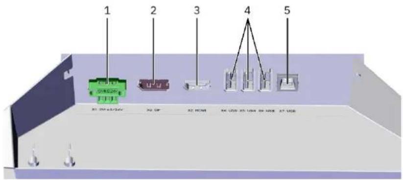
text_image
1 2 3 4 5 81 2W 42/24V 82 0F 82 HDM 84 USB 85 USB 86 USB 87 USBFigure 5-1 Interfaces of the monitors
1 Male connector X1 (supply voltage)
2 Female connector X3 (DisplayPort)
3 Female connector X2 (HDMI)
4 Female connectors X4, X5, X6 (USB 2.0, Type A)
5 Female connector X7 (USB 2.0, Type B)
5.2 Interfaces of the panel PCs
The interfaces of the device are located in the service slot.

text_image
1 2 3 4 5 6 98 7Figure 5-2 Interfaces of the panel PCs
1 Male connector X1 (supply voltage)
2 Female connectors X2, X3 (Ethernet)
3 Female connectors X4/X5 (USB 3.0, Type A), X6 (USB 2.0, Type A)
4 Slot for SD memory card
5 Push-on connectors for functional grounding
6 Extraction tool (SSD mass storage)
7 2.5" SSD mass storage
8 Battery
9 Cover plate with screw fastening (SSD mass storage)
5.3 Supply voltage
The supply voltage is provided via pin strip X1. The appropriate female strip is included in the scope of supply.

WARNING: Dangerous contact voltage
Only qualified personnel may do this work. The personnel must be familiar with the necessary safety precautions.

WARNING: Danger due to overload
Due to the high level of current consumption, the electronics may become overloaded, leading to personal injury and property damage.
The power supply must satisfy the American safety regulation NEC Class 2.

Depending on the device version, install a fuse between the external 24 V DC power supply and the device.
FPM 17.3 xxx FPM 24.8 xxx
Fuse 4 A, slow-blow 4 A, slow-blow
PPC 17.3 xxx PPC 24.8 xxx
Processor Celeron i5 Celeron i5
Fuse 4 A, slow-
blow
6 A, slow-
blow
4 A, slow-
blow
6 A, slow-
blow
Please refer to the technical data for the permissible supply voltage and the current consumption of the device.

NOTE: Damage
The connector pin assignment is not the same for monitors and panel PCs. Refer to the relevant table below for the appropriate connector assignment for your device.
Connector on the monitor: 3-pos. pin strip

Table 5-1 Monitor: Connector pin assignment of the supply voltage
| Pin Function |
| 1 0 V supply voltage (GND) |
| 2 N. C. (not connected), do not use |
| 3 — 24 V supply voltage |
Connector on the panel PC: 4-pos. pin strip

Table 5-2 Panel PC: Connector pin assignment of the supply voltage
| Pin Function |
| 1 Do not use |
| 2 0 V supply voltage (GND) |
| 3 Functional ground (FE) |
| 4 — 24 V supply voltage |
Use a fine-stranded cable with a minimum cross-section of 1 mm^2 and a maximum cross-section of 1.5 mm^2 to connect the supply voltage.
5.4 DisplayPort

NOTE:
- Use cables with a maximum length of 10 m.
5.5 HDMI

NOTE:
- Use cables with a maximum length of 15 m.
5.6 USB
The female connectors conform to the USB 2.0 standard (white interfaces) and the USB 3.0 standard (blue interfaces). The USB 2.0 interfaces are backward-compatible with USB 1.0. The USB 3.0 interfaces are backward-compatible with USB 2.0 and USB 1.0.
5.6.1 Cables

NOTE:
- Use industrial-grade USB cables with a maximum length of 15 m.

For the specification of a suitable cable, please refer to the “Universal Serial Bus Specification”.
5.7 Ethernet
You can integrate the device into an Ethernet network that supports 1 Gbps. Use the 1 Gbit RJ45 LAN ports for this. If necessary, you can download the relevant drivers from the website. Observe the specifications for the network topology.
5.8 Mass storage
Hard disk/Flash – SSD The following options are available for data storage:
- mSATA module (permanently installed)
- 2.5" SSD mass storage with up to 500 GB via SATA (see also Section "Replacing the mass storage" on page 35)
External drives External storage media can be connected via USB interfaces.

NOTE: Data loss
Data can be lost if an external drive is connected or unplugged during operation.
- Switch off the device before connecting or unplugging an external drive.
5.9 Grounding
5.9.1 Basic information on grounding

The devices are supplied with extra-low voltage (ELV). Therefore, the connection of protective ground PE is optional.

NOTE:
- Keep all cable lengths for grounding as short as possible.
- Protective ground PE (PPC xxxx panel PCs/FPM xxxx monitors):
- Use a fine-stranded cable with a minimum cross-section of 1.5 mm ^2 (AWG 16) and a maximum cross-section of 2.5 mm ^2 (AWG 10) for connecting the protective ground.
- Functional ground FE (PPC xxxx panel PCs):
- Use a fine-stranded cable with a minimum cross-section of 1 mm ^2 (AWG 18) and a maximum cross-section of 1.5 mm ^2 (AWG 16) for connecting the functional ground.
- For cable lengths >5 m, use a conductor cross-section of 1.5 mm ^2 (AWG 16). When using functional and protective ground, please observe the following:
- Do not combine functional and protective ground directly at the device, but in the control cabinet.
5.9.2 Grounding of PPC xxxx panel PCs
The PPC xxxx panel PCs are supplied with extra-low voltage (ELV) and require a functional ground FE to ensure compliance with EMC regulations.
- Implement functional ground FE via pin strip X1.
- Optionally, connect protective ground PE to the housing via the slip-on sleeve.
text_image
N.C. 0V PE FE 24 V R11 LAM R12 LAM R13 LAM R14 LAM R15 LAM R16 LAM R17 LAM R18 LAM R19 LAM R20 LAM R21 LAM R22 LAM R23 LAM R24 LAM R25 LAM R26 LAM R27 LAM R28 LAM R29 LAM R30 LAM R31 LAM R32 LAM R33 LAM R34 LAM R35 LAM R36 LAM R37 LAM R38 LAM R39 LAM R40 LAM R41 LAM R42 LAM R43 LAM R44 LAM R45 LAM R46 LAM R47 LAM R48 LAM R49 LAM R50 LAM R51 LAM R52 LAM R53 LAM R54 LAM R55 LAM R56 LAM R57 LAM R58 LAM R59 LAM R60 LAM R61 LAM R62 LAM R63 LAM R64 LAM R65 LAM R66 LAM R67 LAM R68 LAM R69 LAM R70 LAM R71 LAM R72 LAM R73 LAM R74 LAM R75 LAM R76 LAM R77 LAM R78 LAM R79 LAM R80 LAM R81 LAM R82 LAM R83 LAM R84 LAM R85 LAM R86 LAM R87 LAM R88 LAM R89 LAM R90 LAM R91 LAM R92 LAM R93 LAM R94 LAM R95 LAM R96 LAM R97 LAM R98 LAM R99 LAM R100 LAMFigure 5-3 Protective ground PE and functional ground FE on the PPC xxxx panel PCs
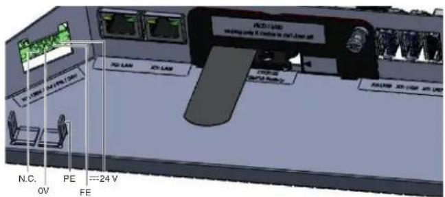
5.9.3 Grounding of FPM xxxx monitors

The FPM xxxx monitors are supplied with extra-low voltage (ELV). Nevertheless, we recommend the connection of protective ground PE.
- Connect protective ground PE (optional) to the housing via the slip-on sleeve.

text_image
0V N.C. ---24 V PE N.C.Figure 5-4 Protective ground PE on the FPM xxxx monitors

The FPM xxxx monitors are operated without functional ground FE.
6 Startup

WARNING: Danger due to overload
Due to the high level of current consumption, the electronics may become overloaded, leading to personal injury and property damage.
The power supply must satisfy the American safety regulation NEC Class 2.

NOTE: Damage to the electronics
The electronics can be damaged if the permissible voltage is exceeded.
- Observe the permissible supply voltage and the current consumption of the device specified in the technical data.

NOTE: Damage to the electronics
The electronics can be damaged if connectors are connected or disconnected while power is still being applied.
- Make sure that no voltage is present when connecting or disconnecting cables.

NOTE: Condensation damage
Condensation may form if the device temperature is different from that of the room.
- Do not switch the device on until its temperature has equalized to the room temperature.

Connect the data cable shielding to the connector housing (EMC).
6.1 Checking for operational readiness
- Make sure that the screw connections between the device and tube adapter/VESA adapter and tube adapter/VESA adapter and connection tube are tightened to the specified torques.
- Make sure that the service slot and the USB flap are completely closed.
6.2 Starting up the device

WARNING: Dangerous contact voltage
Only qualified personnel may do this work. The personnel must be familiar with the necessary safety precautions.
Make sure that no voltage is present at the device or cables when connecting and disconnecting cables.
- Connect the cables to the interfaces.
- Secure the cables to the adapter using the strain relief fixtures.
- Make sure that the 24 V power supply complies with NEC Class 2.
- Connect the device to the power supply.
7 Operating the device
7.1 Switching on and off

NOTE: Damage to the electronics
The electronics can be damaged if the device is switched off and then on again too quickly.
- Make sure that you wait 5 seconds between switching the device off and then on again.
Switching on • Connect the device to the external power supply.
If an operating system is installed, it now starts. When the device is on, the status LED of the monitor lights up. This status LED is located in the bottom right area on the front.
Switching off • Switch off the device by shutting down the operating system.
7.2 Touchscreen
- Operate the multifunctional touchscreen using up to 10 fingers.
It is not only possible to tap elements, swiping and dragging movements are also possible.

The touch calibration data is stored independently of the operating system and does not require any additional calibration by the user.
The necessary driver software is already integrated into the respective operating system.
7.3 WLAN and Bluetooth
These functions can only be used by means of the installed operating system.
8 Component replacement, device defect, and repairs
8.1 Component replacement

NOTE: Danger due to short circuit
A short circuit can occur if components are replaced while the device is still switched on.
- Before replacing components, disconnect the device from the supply voltage.
8.1.1 Battery replacement

WARNING: Explosion hazard
Using the wrong battery type will result in an extremely high risk of explosion.
- Only use batteries of the type recommended by the manufacturer.

NOTE: Risk of thermal stress
High thermal stress may result in faster aging of the battery.
- Operate the device only within its specified ranges.

NOTE: Battery damage
Improper handling can damage or destroy the battery.
Do not do the following with lithium batteries:
- Throw them in a fire
– Solder anything to the cell body
- Recharge them
- Open them
- Short circuit them
- Reverse their polarity
- Heat them above 100°C

NOTE: Explosion hazard due to overheating
- Make sure that the battery is of the correct type and that it is inserted with the correct polarity.
The panel PCs have a lithium battery. The battery supplies the system clock when no supply voltage is present. The battery has a service life of three to five years depending on the load. To see the position of the battery in the service slot, refer to Section “Interfaces of the panel PCs” on page 24.

Only use the recommended battery type:
Lithium battery, type CR2032 (230 mAh/3 V)
- Pull out the battery drawer (pull both sides of the drawer at the same time).
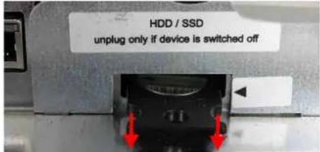
text_image
HDD / SSD unplug only if device is switched offFigure 8-1 Pulling out the battery drawer
- Remove the old battery.
- Press the new battery into the drawer; the battery must engage in the drawer.

Figure 8-2 Inserting the battery in the drawer
The positive and negative pole is indicated on the battery holder.
- Turn the drawer over so that the negative pole is pointing upwards.

Figure 8-3 Turning the battery drawer
- Insert the drawer into its slot; the drawer must engage in the slot.

text_image
HDD / SSD unplug only if device is switched offFigure 8-4 Inserting the battery drawer
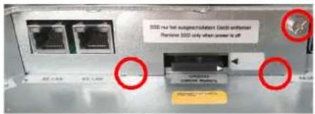
8.1.2 Replacing the mass storage
Removal Remove the cover plate.
- To do so, loosen the mounting screw (PH1 Phillips screwdriver).

text_image
2020 nur bin ausge/absorption limit deferrant Remove 2020 only when power is off 2020.1.48 2020.1.59 WARNING: No change Reteing: YesFigure 8-5 Removing the cover plate
- Holding the mass storage by its extraction tool (white flap), pull it carefully and parallel along its guides out of the slot.

natural_image
Close-up of a network device rear panel showing two Ethernet ports and a labeled switch (no readable text or symbols beyond labels)Figure 8-6 Pulling out the mass storage
- Remove the mass storage at an angle in an upward direction.

natural_image
Close-up of a computer monitor with a green drive and red arrows pointing to the screen area (no visible text or symbols)Figure 8-7 Removing the mass storage
Installation • Insert the mass storage into the slot at an angle.

natural_image
Close-up of a printer's internal structure showing a green drive and red arrows pointing to components (no readable text or symbols)Figure 8-8 Inserting the mass storage
- Lower the mass storage and push it all the way in parallel to its guides.
natural_image
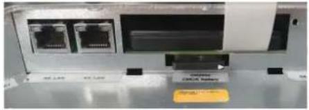
Close-up of a network device rear panel showing two Ethernet ports and a labeled drive (no readable text or symbols)Figure 8-9 Pushing in the mass storage
- Insert the snap-in latches of the cover into the guide slots and close the cover.
text_image
SDD: new bus support installation. Cutoff authentication Remove SDD only when power is offFigure 8-10 Removing the cover plate
- Tighten the mounting screw by hand (PH1 Phillips screwdriver).
8.2 Device defect and repair
Do not open the housing
Repairs may only be carried out by Phoenix Contact. Do not open the housing. If the housing is opened, the function of the device can no longer be ensured.
Defective devices
- Send defective devices back to Phoenix Contact for repair or to receive a replacement device.
9 Maintenance, decommissioning, and disposal
9.1 Maintenance
The following maintenance intervals must be observed:
Table 9-1 Maintenance intervals
| Interval Location | Activity | |
| Daily | Entire device | Visual inspection for loose objects and visible damage |
| Monthly | Mounting screws | Check that they are fixed securely; re-tighten as necessary |
| Every 3 years | BIOS battery | Replace |
9.2 Cleaning
How often you need to clean the system depends on your work and the operating environment. If necessary, follow the on-site cleaning plan.
- Clean and maintain your system regularly.
The devices with IP69K degree of protection have been extensively tested for cleaning under high pressure. For material-friendly and hygienic cleaning, we recommend the use of foam cleaner and subsequent rinsing of the devices. The device series has been tested for a variety of cleaning agents, see Section “Cleaning agents and disinfectants” on page 37.
9.2.1 Cleaning agents and disinfectants
We recommend cleaning the devices using commercially available glass cleaning agents. The following cleaning agents have also been successfully tested and can be used in accordance with the respective dosage and application recommendations:
| Ethanol and isopropanol based | - Deconex Solarsept |
| - Bacillol | |
| - Meliseptol |
| Neutral cleaning agents – P3-Cosa Foam 40– P3-Cosa PUR 80 |
Acidic cleaning agents - P3-Cosa CIP 72
Alkaline cleaning agents – P-Cosa CIP 92
| Quaternary ammonium compounds | - Klercide-CR Biocide A |
| - Deconex Surface AF |
| Disinfectants – Hydrogen peroxide ≤ 3% Recommendation: Wipe off the product completely after use, otherwise water stains may form. |
9.3 Decommissioning and disposal
The device contains a lithium battery to power the system clock when no supply voltage is present. The battery has a service life of three to five years depending on the load. Please also refer to Section "Battery replacement" on page 33.

The device contains valuable recyclable materials, which should be utilized. The electronic circuit board is fitted with a lithium battery.
Dispose of the device separately from other waste, i.e., via an appropriate collection site.
10 Technical data and ordering data
10.1 Technical data
Monitor FPM 17.3 xxx FPM 23.8 xxx
Housing Fully enclosed stainless steel housing
Display 17.3" LED backlight
1920 x 1080 pixels
23.8" LED backlight
1920 x 1080 pixels
Touchscreen PCAP multi-touch/toughened glass
Interfaces 3 x USB 2.0
1 x USB slave
1 x DisplayPort
1 x HDMI
Power supply unit 18 - 30 V — NEC Class 2
Degree of protection IP69K (not verified by UL)
Operating temperature 0°C to +50°C 0°C to +45°C
Dimensions (W x H x D) 431 mm x 261 mm x 68 mm 578 mm x 347 mm x 67 mm
Weight Approx. 5 kg
Approx. 7.5 kg
Vibration
10 m/s²; 2 - 200 Hz (class 3M4 of standard IEC/EN 60721-3-3)
Shock
100m / s^2 ; t = 11 ms (class 3M4 of standard IEC/EN 60721-3-3)
Humidity
10% to 85%, non-condensing
| Panel PC | PPC 17.3 xxx xxx | PPC 23.8 xxx xxx |
| Housing Fully enclosed stainless steel housing | ||
| Display 17.3" LED backlight | 1920 x 1080 pixels | 23.8" LED backlight1920 x 1080 pixels |
| Touchscreen PCAP multi-touch/toughened glass | ||
| Processor Intel® CeleronTM | 1.6 GHz (2980U) or Intel® CoreTM i5 1.9 GHz (4300U) | |
| RAM Up to 8 GB DDR3 | ||
| Mass storage SSD up to 500 | GB or mSATA-SSD up to 128 GB | |
| Network 2 x 1 Gbps Ethernet RJ45 | ||
| Wireless (optional) WLAN: IEEE 802.11ac/a/b/g/nBluetooth V4.2, V4.0 LE, V3.0+HS, V2.1+EDR | ||
| Interfaces 1 x USB 2.0 | 2 x USB 3.0 | |
| Power supply unit 18 - 30 V | NEC Class 2 | |
| Operating system Windows | 10 IoT (64-bit) | |
| Degree of protection IP69K (not verified by UL) | ||
| Operating temperature 0°C to +50°C | 0°C to +45°C | |
| Dimensions (W x H x D) | 431 mm x 261 mm x 68 mm 578 mm x 347 mm x 67 mm | |
| Weight | Approx. 5 kg | Approx. 7.5 kg |
| Vibration | 10 m/s2; 2 - 200 Hz (class 3M4 of standard IEC/EN 60721-3-3) | |
| Shock | 100 m/s2; t = 11 ms (class 3M4 of standard IEC/EN 60721-3-3) | |
| Humidity | 10% to 85%, non-condensing | |
10.2 Ordering data
Products
| Description Type Order No. Pcs./Pkt. | |||
| Hygiene monitor with 43.9 cm/17.3" TFT display (capacitive multi-touchscreen), 1920 x 1080 pixels (Full HD) in fully enclosed stainless steel housing without screws or sharp edges. With shatter protection film. | FPM 17.3 69K SP 1261656 1 | ||
| Hygiene monitor with 43.9 cm/17.3" TFT display (capacitive multi-touchscreen), 1920 x 1080 pixels (Full HD) in fully enclosed stainless steel housing without screws or sharp edges. | FPM 17.3 69K 1261657 1 | ||
| Hygiene monitor with 60.5 cm/23.8" TFT display (capacitive multi-touchscreen), 1920 x 1080 pixels (Full HD) in fully enclosed stainless steel housing without screws or sharp edges. | FPM 23.8 69K 1261659 1 | ||
| Hygiene monitor with 60.5 cm/23.8" TFT display (capacitive multi-touchscreen), 1920 x 1080 pixels (Full HD) in fully enclosed stainless steel housing without screws or sharp edges. With shatter protection film. | FPM 23.8 69K SP 1261662 1 | ||
| Hygiene PPC 43.9 cm/17.3" TFT display (capacitive multi-touchscreen), 1920 x 1080 pixels (Full HD) in fully enclosed stainless steel housing without screws or sharp edges. With configurable processor, RAM, data storage, and operating system. | PPC 17.3 AIO 69K 1262469 1 | ||
| Hygiene PPC with 60.5 cm/23.8" TFT display (capacitive multi-touchscreen), 1920 x 1080 pixels (Full HD) in fully enclosed stainless steel housing without screws or sharp edges. With configurable processor, RAM, data storage, and operating system. | PPC 23.8 AIO 69K 1262470 1 | ||
| Tube adapter TUBE ADAPTER 1280671 1 | |||
| VESA adapter | VESA ADAPTER 1280672 1 |
A Appendix for document lists
A 1 List of figures
Section 3
Figure 3-1: Versions with tube adapter/VESA adapter .... 13
Section 4
Figure 4-1: Template for support arm mounting .... 16
Figure 4-2: Countersinking the connection tube .... 16
Figure 4-3: Template for connection tube mounting .... 16
Figure 4-4: Countersinking the connection tube ....17
Figure 4-5: Side view with tube adapter/service slot cover .... 18
Figure 4-6: Removing the service slot cover ....19
Figure 4-7: Loosening the screws of the cloverleaf holders ....19
Figure 4-8: Removing the cloverleaf seals ....20
Figure 4-9: Cable cross-section for cloverleaf seals 20
Figure 4-10: Mounting the VESA adapter on the device 21
Figure 4-11: Mounting the VESA adapter on the connection system ....21
Figure 4-12: Position of the seal and screw connection for the tube adapter ....22
Section 5
Figure 5-1: Interfaces of the monitors ....23
Figure 5-2: Interfaces of the panel PCs ....24
Figure 5-3: Protective ground PE and functional ground FE on the PPC xxxx panel PCs .... 28
Figure 5-4: Protective ground PE on the FPM xxxx monitors ....28
Section 8
Figure 8-1: Pulling out the battery drawer ....34
Figure 8-2: Inserting the battery in the drawer 34
Figure 8-3: Turning the battery drawer .... 34
Figure 8-4: Inserting the battery drawer ....34
Figure 8-5: Removing the cover plate ....35
Figure 8-6: Pulling out the mass storage .... 35
FPM xxxx hygiene monitors / PPC xxxx hygiene panel PCs
Figure 8-7: Removing the mass storage .... 35
Figure 8-8: Inserting the mass storage ....35
Figure 8-9: Pushing in the mass storage ....36
Figure 8-10: Removing the cover plate .... 36
A 2 List of tables
Section 5
Table 5-1: Monitor: Connector pin assignment of the supply voltage....25
Table 5-2: Panel PC: Connector pin assignment of the supply voltage....26
Section 9
Table 9-1: Maintenance intervals....37
A 3 Index
B
Battery 33,38
Bluetooth.... 31
C
Cleaning.... 37
Cleaning agents 37
Component replacement.... 33
D
Decommissioning 38
Device defect 36
Disinfectants 37
DisplayPort.... 26
Disposal 38
E
Ethernet 26
F
Field of application 5
Functional ground 28
G
Grounding 27
|
Intended use .... 5
Interfaces
Monitors 23
Panel PCs 24
M
Maintenance 37
Mass storage 27,35
Mounting
Connection pipe 15
Stand.... 16
Support arm.... 15
Tube adapter.... 22
VESA adapter....19
Mounting versions.... 17
P
Protective ground.... 27
R
Repairs 36
S
Safety notes....6
Startup 30
Storage 11
Storage location.... 11
Supply voltage 25
Switching off 31
Switching on 31
T
Technical data 39
Monitor 39
Panel PC 40
Touchscreen.... 31
Transport 11
U
Unpacking.... 11
USB 26
V
Versions.... 13
W
WLAN 31
Please observe the following notes
General Terms and Conditions of use for technical documentation
Phoenix Contact reserves the right to alter, correct, and/or improve the technical documentation and the products described in the technical documentation at its own discretion and without giving prior notice, insofar as this is reasonable for the user. The same applies to any technical changes that serve the purpose of technical progress.
The receipt of technical documentation (in particular user documentation) does not constitute any further duty on the part of Phoenix Contact to furnish information on modifications to products and/or technical documentation. You are responsible to verify the suitability and intended use of the products in your specific application, in particular with regard to observing the applicable standards and regulations. All information made available in the technical data is supplied without any accompanying guarantee, whether expressly mentioned, implied or tacitly assumed.
In general, the provisions of the current general Terms and Conditions of Phoenix Contact apply exclusively, in particular as concerns any warranty liability.
This manual, including all illustrations contained herein, is copyright protected. Any changes to the contents or the publication of extracts of this document are prohibited.
Phoenix Contact reserves the right to register its own intellectual property rights for the product identifications of Phoenix Contact products that are used here. Registration of such intellectual property rights by third parties is prohibited.
Other product identifications may be afforded legal protection, even where they may not be indicated as such.
How to contact us
Internet
Up-to-date information on Phoenix Contact products and our Terms and Conditions can be found on the Internet at: phoenixcontact.com
Make sure you always use the latest documentation. It can be downloaded at: phoenixcontact.net/products
Subsidiaries
If there are any problems that cannot be solved using the documentation, please contact your Phoenix Contact subsidiary. Subsidiary contact information is available at phoenixcontact.com.
Published by PHOENIX CONTACT GmbH & Co. KG
PHOENIX CONTACT Development and Manufacturing, Inc. 586 Fulling Mill Road Middletown, PA 17057 USA
Should you have any suggestions or recommendations for improvement of the contents and layout of our manuals, please send your comments to: tecdoc@phoenixcontact.com
PHOENIX CONTACT GmbH & Co. KG
Flachsmarktstraße 8
32825 Blomberg, Germany
Phone: +49 5235 3-00
Fax: +49 5235 3-41200
E-mail: info@phoenixcontact.com
phoenixcontact.com
