AXL SE DO16/1 - Uncategorized Phoenix Contact - Free user manual and instructions
Find the device manual for free AXL SE DO16/1 Phoenix Contact in PDF.

User questions about AXL SE DO16/1 Phoenix Contact
0 question about this device. Answer the ones you know or ask your own.
Ask a new question about this device
Download the instructions for your Uncategorized in PDF format for free! Find your manual AXL SE DO16/1 - Phoenix Contact and take your electronic device back in hand. On this page are published all the documents necessary for the use of your device. AXL SE DO16/1 by Phoenix Contact.
USER MANUAL AXL SE DO16/1 Phoenix Contact
natural_image
Illustration of a row of connected server racks with orange connectors, no text or symbols presentAxioline Smart Elements
User manual
User manual
Axioline Smart Elements
UM EN AXL SE SYS INST, Revision 03
2023-04-03
This user manual is valid for all Axioline Smart Elements (AXL SE ...)
Table of contents
1 For your safety....5
1.1 Identification of warning notes .... 5
1.2 Qualification of users....5
1.3 Field of application of the product....6
1.3.1 Intended use 6
1.3.2 Product changes 6
2 Documentation landscape of Axioline Smart Elements....7
2.1 Available documents ...... 7
2.2 Documentation on the Internet 8
2.3 Purpose of this user manual 8
3 The Axioline Smart Elements product group....9
3.1 Axioline Smart Elements....9
3.2 Use in an Axioline F station....9
4 Product description....10
4.1 General description ...... 10
4.2 Approvals 13
4.3 Item designations .... 13
4.4 Color and marking ....15
5 Transport, storage, and unpacking 17
5.1 Transport....17
5.2 Storage....17
5.3 Unpacking 17
6 Mounting and removal of Smart Elements 18
6.1 Safety notes for mounting and removal 18
6.1.1 Qualification of users 18
6.1.2 General safety notes 18
6.1.3 Additional safety notes for the low voltage range 19
6.2 Mounting position 20
6.3 Mounting Smart Elements 21
6.4 Removing Smart Elements 21
7 Connecting or removing cables 22
7.1 Cables connected to Smart Elements 22
7.2 Conductor cross-sections, stripping and insertion lengths 23
7.3 Terminal point with spring lever and touch connection 25
7.4 Connecting unshielded cables 26
7.5 Connecting shielded cables 27
7.6 Removing cables from the terminal point.... 27
8 Supply voltages 28
8.1 Required supply voltages 28
8.2 Power supply requirements 29
8.3 Smart Elements with 1-conductor technology .... 30
9 Diagnostic and status indicators 31
10 Process, parameter and diagnostic data....33
10.1 Process data 33
10.2 Parameter and diagnostic data (PDI channel) 33
10.3 Saving of parameters 34
11 Device replacement, device defects, and repairs 35
11.1 Device replacement.... 35
11.2 Device defects and repairs.... 35
12 Maintenance, decommissioning, and disposal 36
12.1 Maintenance....36
12.2 Decommissioning and disposal.... 36
13 Technical data and ordering data .... 37
13.1 Technical data....37
13.2 Ordering data 40
A Technical appendix: altitudes above 3000 m....42
B Index....43
A Revision history 45
1 For your safety
Read this user manual carefully and keep it for future reference.
1.1 Identification of warning notes

This symbol indicates hazards that could lead to personal injury.
There are three signal words indicating the severity of a potential injury.
DANGER
Indicates a hazard with a high risk level. If this hazardous situation is not avoided, it will result in death or serious injury.
WARNING
Indicates a hazard with a medium risk level. If this hazardous situation is not avoided, it could result in death or serious injury.
CAUTION
Indicates a hazard with a low risk level. If this hazardous situation is not avoided, it could result in minor or moderate injury.

This symbol together with the NOTE signal word warns the reader of actions that might cause property damage or a malfunction.

Here you will find additional information or detailed sources of information.
1.2 Qualification of users
The use of products described in this user manual is oriented exclusively to electrically skilled persons or persons instructed by them. The users must be familiar with the relevant safety concepts of automation technology as well as applicable standards and other regulations.
1.3 Field of application of the product
1.3.1 Intended use
You can integrate Axioline Smart Elements into systems with the Smart Element interface.
The Axioline Smart Elements have IP20 degree of protection and can be used in closed control cabinets or control boxes (junction boxes) with IP54 protection or higher.

Axioline Smart Elements are designed for use in industrial environments.
In the following, the terms "Axioline Smart Elements" and "Smart Elements" are used interchangeably.
1.3.2 Product changes
Modifications to hardware and firmware of the device are not permitted.
Incorrect operation or modifications to the device can endanger your safety or damage the device. Do not repair the device yourself. If the device is defective, please contact Phoenix Contact.
2 Documentation landscape of Axioline Smart Elements
2.1 Available documents
The documentation for the Axioline Smart Elements product group is modular, providing you with the optimum information to meet your requirements.
Table 2-1 Axioline Smart Elements documentation
| Document Contents | |
| Comprehensive information on Smart Elements | |
| User manual“Axioline Smart Elements”UM EN AXL SE SYS INST(this user manual) | This user manual is the generic user manual for Axioline Smart Elements.It describes the Axioline Smart Elements product group and everything about mounting, removal and wiring of Smart Elements. |
| Comprehensive information on the Axioline F system (including Axioline F backplane) | |
| User manual“Axioline F: System and installation”UM EN AXL F SYS INST | This manual is the generic system manual for Axioline F.It describes the Axioline F product group and everything about mounting, removal and wiring of Axioline F modules regardless of a higher-level network. |
| Basic information on a Smart Element | |
| Packing slip Smart Elements with a safety function are supplied with a packing slip. It contains key information on the electrical installation.This includes, for example:- EU declaration of conformity-Safety notes-Brief description/Intended use-Mounting, removal, and installation- Additional applicable documentationSmart Elements without a safety function are not supplied with a packing slip.For use within an Axioline F system, the packing slips for the Axioline F backplanes also contain information on Smart Elements. | |
| Tubular bag printing The tubular bag printing contains key information on the electrical installation. | |
| Printing on the Smart Element | Terminal point assignment is printed on the side of the Smart Element. |
| User manuals for safe Smart Elements | The user manual for each safe Smart Element contains the complete information required for use. |
| Data sheets The data sheet for each Smart Element contains the complete information required for use.This includes at the very least:- Function description- Technical data- Connection assignment or terminal point assignment- Local diagnostic and status indicators- Connection examples | |
Table 2-1 Axioline Smart Elements documentation [...]
| Document Contents | |
| Additional information on a Smart Element | |
| Quick start guides Quick-start guides | are available for various topics. A quick-start guide describes the startup of a Smart Element step by step using an example. |
| Application notes Application notes p | provide additional information on special topics. |
2.2 Documentation on the Internet
The documentation can be downloaded at phoenixcontact.net/
Generate product PDF
Click the "Generate product PDF" link to see the selected up-to-date information. It provides a short overview of the Smart Element. The generated PDF file contains the essential product information. If you require further information, you can use the "Downloads" tab.
Downloads
You can access the complete documentation and all other downloads related to a product via the "Downloads" item in the "Product Details" section.
2.3 Purpose of this user manual
This user manual provides information on the Axioline Smart Elements product group. It describes the product group and everything about mounting, removal, and wiring of Smart Elements. This description is independent of the system in which you use Smart Elements and independent of a higher-level network.
3 The Axioline Smart Elements product group
3.1 Axioline Smart Elements
Axioline Smart Elements are compact, pluggable I/O elements. They are particularly easy to handle during configuration, installation, and startup.
Compact
Eight or 16 terminal points on a base area of 15 mm x 62 mm provide an extremely compact housing design.
The large conductor cross-section of 1.5 mm^2 with ferrule including a plastic collar on a 3.5 mm pitch for I/O signals ensures low voltage drops, even over longer conductor lengths.
Easy handling
Push-in connection technology reduces signal line installation times, thanks to conductor connection without tools.
Minimize your startup time with Axioline Smart Elements, as they require little to no parameterization effort during startup or when replaced.
The release mechanism enables quick and easy mounting and removal.
3.2 Use in an Axioline F station
Axioline F backplanes are available for integrating Axioline Smart Elements into an Axioline F station. Depending on the version, the backplanes feature four or six slots for Axioline Smart Elements. You can insert the Axioline Smart Elements at any position in the backplane.
Within an Axioline F station, the backplanes provide the I/O voltage and communications power supply for the Smart Elements.
You can combine Axioline F modules and Axioline Smart Elements in any way in an I/O station.
Figure 3-1 Example: Smart Elements in an Axioline F station
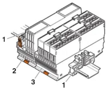
text_image
Technical diagram of an electrical connector with numbered parts labeled 1, 2, and 31 End bracket
2 Axioline F bus coupler
3 Axioline F backplane with Axioline Smart Elements plugged in
4 Product description
4.1 General description
Structure
Figure 4-1 Components of a Smart Element
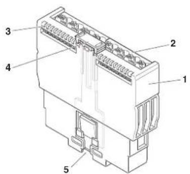
text_image
Technical diagram of an electrical connector with numbered parts labeled 1 through 51 Housing
2 Terminal points for I/O connection, depending on the housing version
3 Diagnostic and status indicators, depending on the Smart Element type
4 Release mechanism
5 Smart Element interface
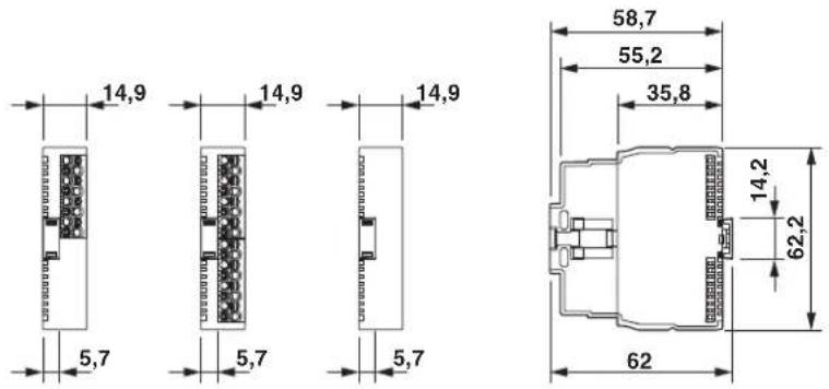
Housing versions
Smart Elements for extra-low voltage are available in three housing versions, see Figure 4-2:
– Smart Elements with 16 terminal points
- Smart Elements with 8 terminal points
– Smart Elements without terminal points
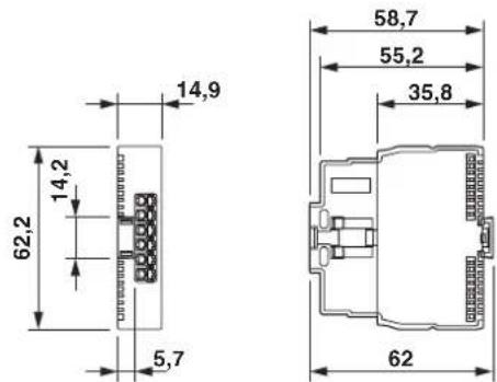
The relay module is accommodated in a separate housing version, see Figure 4-3.
Dimensions of extra-low voltage versions
In addition to the housing versions for extra-low voltage, Figure 4-2 also shows the dimensions of the Smart Elements. The dimensions are identical, independent of the number of terminal points.
Figure 4-2 Housing versions and dimensions of Smart Elements for extra-low voltage
Dimensions of the relay module
Figure 4-3 Housing version and dimensions of the relay module
Smart Elements with various functions are available within the Axioline Smart Elements product group.
- Smart Elements for the input or output of digital or analog signals
– Smart Elements for temperature measurement
– Smart Elements for communication - Smart Elements for open and closed-loop control, and position detection
一...
Voltage ranges
Smart Elements are available for the protective extra-low voltage (PELV) and the low voltage range. Smart Elements for both ranges can be installed right next to each other.
Table 4-1 Voltage ranges of the Smart Elements
| Voltage range Nominal voltage used | Permissible voltage range | Examples |
| Protective extra-low voltage (extra-low voltage) | 24 V DC | 19.2 V DC ... 30 V DC |
| Low voltage | 220 V DC230 V AC | 19.2 V DC ... 253 V DC19.2 V AC ... 265 V AC(50 Hz ... 60 Hz) |

The instructions given in this user manual and in the product-specific documentation must be followed during installation and startup.
Particularly observe: "Mounting and removal of Smart Elements" on page 18.
Mounting location
Smart Elements have IP20 degree of protection. They can be used in closed control cabinets or control boxes (junction boxes) with IP54 degree of protection in accordance with EN 60529 or higher.
Mounting
A Smart Element is snapped onto its slot without using any tools. See Section "Mounting and removal of Smart Elements" on page 18.
Removal
To remove a Smart Element from its slot, pull the release mechanism upwards. See Section "Mounting and removal of Smart Elements" on page 18.
Communications supply voltage ( U_SE )
The communications supply voltage of the Smart Element is provided via the Smart Element interface.
I/O supply voltage ( U_P )
The I/O supply voltage of the Smart Element is provided via the Smart Element interface.
I/O connection
The I/O devices are connected directly via the terminal points of the Smart Element.
Grounding and shielding
The system providing the slot for the Smart Element has to provide a grounding and shielding concept.
Diagnostics The Smart Elements feature diagnostic and status indicators.
For the diagnostic options of a Smart Elements, please refer to the associated data sheet.
4.2 Approvals
For the latest information about approvals of Smart Elements, please visit phoenixcontact.net/product/
4.3 Item designations
The item designation helps you to identify the function of a Smart Element.
| Product group Function and number of inputs or outputs |
| Conductor connection |
| Function extension |
Examples: AXL SE AI4 I 4-20
AXL SE AO4 U 0-10
AXL SE DI16 /1
AXL SE RS485
AXL SE INC1 SYM
Table 4-2 Structure of the item designations
| Product group AXL SE Axioline Smart Elements | ||
| Function DI Digital input | ||
| DO | Digital output | |
| DOR | Relay output | |
| SDI | Safe digital input | |
| SDO | Safe digital output | |
| PSDI | Safe digital input in a PROFIsafe system | |
| PSDO | Safe digital output in a PROFIsafe system | |
| AI | Analog input | |
| AO | Analog output | |
| RTD | Analog input for the connection of resistance temperature detectors | |
| CNT | Counter | |
| INC | Incremental encoder input | |
| RS485 | Communication, serial data transmission via RS-485 | |
| RS232 | Communication, serial data transmission via RS-232 | |
| IOL | IO-Link | |
| PD | Potential distribution | |
| Function SC Slot cover for an unused Smart Element slot | ||
| Number of inputs or outputs | 1 ... 16 | 1 channel ... 16 channels |
Table 4-2 Structure of the item designations [...]
| Conductor connection /1 1-conductor | ||
| /2 2-conductor | ||
| Function extension I 4-20 Current 4 mA ... 20 mA | ||
| U 0-10 Voltage 0 V ... 10 V | ||
| PT100 Measurement resistor Pt 100 | ||
| PT1000 Measurement resistor Pt 1000 | ||
| SYM Symmetrical incremental encoders | ||
| ASYM Asymmetrical incremental encoder | ||
| NPN NPN-wired | ||
| W 230 Changeover contact, 230 V AC | ||
| 2A 2 A output | ||
| EF Extended function | ||
| 24V | ||
| GND | ||
4.4 Color and marking
Color The following housing colors are used for Smart Elements.
Table 4-3 Housing colors
| Color Similar RAL color Use | ||
| Traffic gray A RAL 7042 Standard | ||
| Zinc yellow RAL 1018 Safety |
Function
The function can be read even if the Smart Elements are plugged in.
Terminal points Starting from the top, the terminal points are marked with 0, 1 to 15, maximum. In addition, each terminal point used is marked on the side depending on its function.

text_image
0 1 2 3 4 5 6 7 8 9 10 11 12 13 14 15 16 E 01 02 03 04 05 06 07 08 09 10 11 12 13 14 15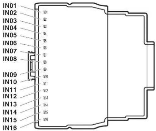
text_image
IN01 IN02 IN03 IN04 IN05 IN06 IN07 IN08 IN09 IN10 IN11 IN12 IN13 IN14 IN15 IN16Figure 4-4 Terminal point marking (example: AXL SE DI16/1)
Indication elements
Diagnostics and status indicators are marked in accordance with their function. For the meaning, please refer to the data sheet specific to the Smart Element.
Equipment identification by the user
You can provide the Smart Element with an equipment identification. Two options are available:
- Stick a label to the release mechanism (1 in Figure 4-5).
Or
- Snap a marker onto the release mechanism.
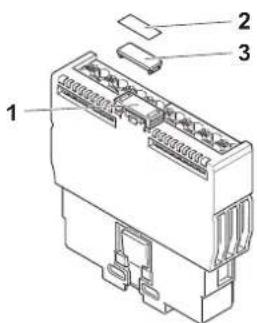
text_image
Technical diagram of an electrical connector with labeled parts 1, 2, and 3Figure 4-5 Equipment identification
1 Position for equipment ID on the release mechanism
2 Label for self-adhesion (see Table 4-4)
3 Marker for snapping on (see Table 4-4)
The dimensions of the marking area are 12 mm x 5.4 mm.
You can use the following marking material provided by Phoenix Contact:
Table 4-4 Marking material
| No. in Figure 4-5 | Description Type Item No. Pcs./ | Pkt. | ||
| 2 Label, continuous, cassette, transparent with black imprint, mounting type: adhesive, can be marked with THERMOFOX | MM-TML (EX4,2)R C1 TR/BK 0803979 1 | |||
| 2 Marker strip, roll, white, unmarked, can be marked with: THERMOMARK ROLL 2.0, THERMOMARK ROLL, THERMOMARK ROLL X1, THERMOMARK ROLLMASTER 300/600, THERMOMARK X1.2, mounting type: adhesive, for terminal block width: 5 mm, lettering field size: continuous x 5 mm | SK 5,0 WH:REEL 0805221 1 | |||
| 3 Markers, 24-section, unmarked, can be marked with THERMOMARK CARD and BLUEMARK, color: white | UM6M-TM (5X12) 0830928 10 | |||
| 3 Markers, sheet, white, unmarked, can be marked with: THERMOMARK CARD, THERMOMARK CARD 2.0, THERMOMARK PRIME, BLUEMARK ID, BLUEMARK ID COLOR, TOPMARK LASER, TOPMARK NEO, mounting type: snap into a high marker groove, for terminal block width: 5.2 mm, lettering field size: 4.17 mm x 11.3 mm | UCT6M-TM 5 | 0830756 10 | ||
5 Transport, storage, and unpacking

NOTE: Electrostatic discharge
Electrostatic discharge can damage or destroy components. When handling the device, observe the necessary safety precautions against electrostatic discharge (ESD) in accordance with EN 61340-5-1 and IEC 61340-5-1.
5.1 Transport
Smart Elements are delivered in a tubular bag.
- Please observe the notes on the packaging.
Suitable transport packaging
- Only transport the device in its original packaging or in packaging suitable for transport.
Technical data and environmental conditions
- For transport, observe the humidity and air pressure specifications, and the temperature range.
See Section "Technical data" on page 37.
5.2 Storage
Suitable storage location The storage location must meet the following requirements:
- Dry
– Protected from unauthorized access - Protected from harmful environmental influences such as UV light
Technical data and environmental conditions
- For storage, observe the humidity and air pressure specifications, and the temperature range.
See Section "Technical data" on page 37.
5.3 Unpacking
Checking the delivery • Check the delivery for damage and completeness.
- Submit claims for any transport damage immediately.
6 Mounting and removal of Smart Elements
6.1 Safety notes for mounting and removal
6.1.1 Qualification of users
The use of products described in this data sheet is oriented exclusively to electrically skilled persons or persons instructed by them. The users must be familiar with the relevant safety concepts of automation technology as well as applicable standards and other regulations.
6.1.2 General safety notes

NOTE: Electrostatic discharge
Electrostatic discharge can damage or destroy components. When handling the device, observe the necessary safety precautions against electrostatic discharge (ESD) in accordance with EN 61340-5-1 and IEC 61340-5-1.
Removing or inserting a Smart Element

NOTE: Damage to contacts or malfunction
- Before performing work on a Smart Element, disconnect the Smart Element from power.
This means:
- Disconnect the connected I/O devices from power.
- Switch off I/O supply voltage U P.
- Switch off communications voltage U SE.
For the system in which the Smart Element is used, this means the following: Switch off the voltage that generates U_SE .
6.1.3 Additional safety notes for the low voltage range
Installing the system
Install the system in accordance with the requirements of EN 50178.

WARNING: Dangerous contact voltage
Please note that there are dangerous contact voltages when working on circuits that do not meet protective extra-low voltage requirements.
- The Axioline Smart Elements for the low voltage range may only be mounted and removed when the power supply is disconnected.
- When working on Smart Elements and wiring, always switch off the supply voltage and ensure it cannot be switched on again.
- The Smart Elements for the low voltage range must only be operated in a closed control cabinet.
Failure to observe these instructions can lead to damage to health or even life-threatening injury.

WARNING: Dangerous contact voltage in the event of ground faults
Please note that there are dangerous contact voltages when working on circuits that do not meet protective extra-low voltage requirements.
- Only operate the Smart Elements for the low voltage range in grounded grids.

Additionally observe the information in the product-specific data sheets.
6.2 Mounting position
The mounting position depends on the system in which the Smart Element is used.
Mounting position in an Axioline F station
For Axioline F backplanes, only wall mounting on a horizontal or vertical DIN rail is permitted (6.3).
Wall mounting on a horizontal DIN rail on the wall is the preferred mounting position (6.3, A). This mounting position provides optimum air flow for the Smart Elements.
Figure 6-1 Mounting positions

natural_image
Front view of a multi-chamber industrial control unit with multiple modules and connectors (no visible text or labels)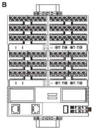
text_image
B6.3 Mounting Smart Elements
A Smart Element and its slot are mechanically designed in such a way that you can only insert the Smart Element in one direction.
- Insert the Smart Element vertically into its slot (Figure 6-2, A).
- Push the release mechanism into the guide as far as it will go (Figure 6-2, B). This latches the Smart Element.
Figure 6-2 Inserting and latching the Smart Element in its slot
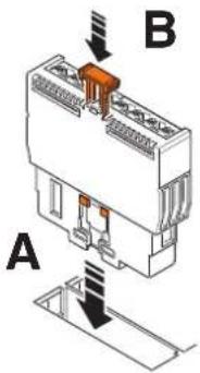
text_image
A B6.4 Removing Smart Elements
- Before removing a Smart Element, you might have to remove the inserted cables. See Section "Connecting or removing cables" on page 22.
- To remove the Smart Element from its slot, pull the release mechanism vertically upwards (Figure 6-3, A).
• Pull the Smart Element out of its slot (Figure 6-3, B).
Figure 6-3 Removing the Smart Element from its slot

text_image
A B7 Connecting or removing cables
7.1 Cables connected to Smart Elements
The cables for I/O devices are directly connected to the Smart Elements.

For use in applications in which UL approval is required:
Observe any specifications in the documentation specific to the Smart Element used, and the rating on the Smart Element.
When using Smart Elements, you can use rigid and flexible cables, with or without ferrules.
Please observe the following when wiring:
– Ensure strain relief in accordance with DIN EN 62444, IEC 62444 for all cables.
- Make sure to install the conductor in the middle of the wiring space, especially with small cross-sections.

If using ferrules, use those which correspond to the specifications in
Section "Conductor cross-sections, stripping and insertion lengths" on page 23.
7.2 Conductor cross-sections, stripping and insertion lengths

For electrical and/or thermal reasons, it may not be possible to use the minimum conductor cross-sections specified here for certain Smart Elements.
Therefore, always observe the information in the documentation specific to the Smart Element.
Conductor cross-sections
Table 7-1 Permissible conductor cross-sections for Push-in connection technology (without using the spring lever for inserting the conductor)
| Conductor Cross-section | |
| Rigid | 0.5 mm^2 .... 1.5 mm^2 (AWG 20 ... 16) |
| Flexible with ferrule without insulating collar (A ...) orwith insulating collar (Al ...) | |
| Flexible with TWIN ferrule with insulating collar (AI-TWIN ...) 0.5 mm | ^2 (AWG 20) |

Flexible cables without ferrules are only suitable for Push-in connection technology when using the spring lever.
Table 7-2 Permissible conductor cross-sections when using the spring lever for inserting the conductor
| Conductor Cross-section | |
| Rigid | 0.25 mm^2 .... 1.5 mm^2 (AWG 24 ... 16) |
| Flexible with ferrule without insulating collar (A ...) orwith insulating collar (Al ...) | |
| Flexible without ferrule | |
| Flexible with TWIN ferrule with insulating collar (AI-TWIN ...) 0.5 mm | ^2 (AWG 20) |
Table 7-3 Stripping lengths and ferrule lengths
| Cross-section Length | |
| 0.25 mm^2 .... 1.5 mm^2 (AWG 24 ... 16) 8 mm | |
| TWIN ferrules: 0.5 mm^2 (AWG 20) 10 mm |
Stripping and insertion lengths

NOTE: Malfunction when the conductor is not securely fixed
To ensure secure fixing and correct functioning: Make sure that the stripping length of a conductor without ferrule or the insertion length of a conductor with ferrule corresponds to the specifications. For crimping, we recommend the CRIMPFOX 6, CRIMPMFOX DUO 10, or CRIMPFOX 10T-F crimping pliers for trapezoidal crimp, see Section "Ordering data for accessories" on page 40. According to the current state, they meet the general conditions with regard to the wiring space for Axioline Smart Elements (in accordance with DIN EN 60947-1 (DIN VDE 0660-100)-A1 internal cylindrical gauge).
TWIN ferrules When using TWIN ferrules, please observe the following:
Table 7-4 Use and alignment of TWIN ferrules
| Terminal point | Use/alignment |
| 0 TWIN ferrule is not permitted. | |
| 1 ... 14 Align the TWIN ferrules vertically. | |
| 15 Align the TWIN ferrules horizontally. | |
Figure 7-1 Use and alignment of TWIN ferrules

text_image
0 1 2 3 4 5 6 7 8 9 10 11 12 13 14 15
Observe any information in the data sheets for the Smart Elements.

Single ferrule

TWIN ferrule (vertical insertion)

TWIN ferrule (horizontal insertion)
Ferrules
CABLE-FLK14/AX- IO/OE/0,14/...
See Section "Ordering data" on page 40.
Deviating from the above specified conductor cross-sections, the use of assembled CABLE-FLK14/AXIO/OE/0,14/... round cables is permitted for digital modules with 1-conductor connection technology. The conductors of these cables are fitted with ferrules and have a conductor cross-section of 0.14 mm ^2 , AWG 26.
If round cables are approved for a module, these are listed in the module ordering data.

UL approval not required
For applications with UL approvals, the AWG 24-16 conductor cross-section has been certified.
Due to the smaller conductor cross-section of AWG 26, UL approval is not required when using the Smart Element in combination with a round cable.
7.3 Terminal point with spring lever and touch connection
When using the screwdriver, pay attention to the position of the spring lever to the assigned terminal point.
When testing the signal with a measuring probe, pay attention to the position of the touch connection to the assigned terminal point.
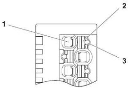
Figure 7-2 Terminal point with associated spring lever and associated touch connection
text_image
1 2 31 Terminal point
2 Associated spring lever
3 Touch connection (for test probes, see Section "Ordering data" on page 40)
7.4 Connecting unshielded cables
Wire the Smart Element in accordance with your application.

For the terminal point assignment, please refer to the data sheet for the Smart Element.
When wiring, proceed as follows:
- Strip 8 mm off the cable.
Without tools Suitable for:
- Conductor cross-sections from 0.5 mm ^2
- Rigid cables
- Flexible cables with ferrules
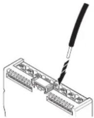
- Insert the cable into the terminal point. It is clamped into place automatically.
Figure 7-3 Connecting a cable without using tools
natural_image
Diagram of a screwdriver inserted into an electronic connector housing (no text or symbols visible)With tools Suitable for:
- Rigid cables
- Flexible cables
-
Flexible cables with ferrules
-
Open the spring by pressing the spring lever using the screwdriver (Figure 7-4, A).
Use a bladed screwdriver with a blade width of 2.5 mm, for example.
Phoenix Contact recommends using the SZS 0,4x2,5 screwdriver (see Section "Ordering data" on page 40). - Insert the cable into the terminal point (Figure 7-4, B).
- Remove the screwdriver to secure the cable.
Figure 7-4 Connecting a cable using tools
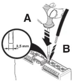
text_image
A 2,5 mm B7.5 Connecting shielded cables

Smart Elements do not feature an option to connect shielding.
For shielding, use the shielding concept of the system in which you use the Smart Element.
Please note in general:
- Observe the connection notes of the manufacturer of the sensors, actuators, encoders, etc.
- Do not use the shield contact as a strain relief. Carry out shielding and strain relief separately.
- For installation in a control cabinet: Connect the cable shield to functional ground at a suitable point immediately after the cables enter the control cabinet. Further route the cable in the control cabinet in a shielded manner.
- If a closed control cabinet is not available, connect the shield to a shield bus.
- Connect the shielding in accordance with the specifications for the system in which you are using the Smart Element.
Within an Axioline F station, the AXL SHIELD SET Axioline shield connection set is available for optimum connection directly in front of the module, see UM EN AXL F SYS INST user manual.
In general, you can use Phoenix Contact products for shielding, see phoenixcontact.net/webcode/#0845.
7.6 Removing cables from the terminal point
- To remove a cable from the terminal point, press on the spring lever using a suitable tool. This opens the terminal point (Figure 7-5, A).
A suitable tool is, for example, a bladed screwdriver with a blade width of 2.5 mm. Phoenix Contact recommends using the SZS 0,4x2,5 screwdriver (see Section "Ordering data" on page 40).
- Remove the conductor (Figure 7-5, B).
Figure 7-5 Removing the cable
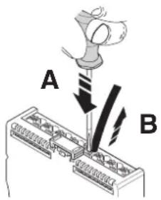
text_image
A B8 Supply voltages
8.1 Required supply voltages
A Smart Element requires the following supply voltages:
- Communications power supply for the Smart Element U SE
- I/O supply voltage U P
The Smart Element receives both supply voltages via the Smart Element interface. Technical data: see Section "Technical data" on page 37.
If a Smart Element additionally needs to be supplied with voltage, it is fed in directly at the Smart Element, e.g., AXL SE DO4/2 2A EF. See product-specific data sheet.
Example of an internal basic circuit diagram
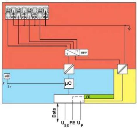
Figure 8-1 shows that the Smart Element receives supply voltages U_SE and U_P from the system, in which the Smart Element is used.
Figure 8-1 Internal wiring of the terminal points (AXL SE AI4 I 4-20)
flowchart
graph TD
    A["Power Supply"] --> B["μC"]
    B --> C["FE"]
    C --> D["Output"]
    E["Input"] --> F["Ground"]
    G["Input"] --> H["Ground"]
    I["Input"] --> J["Ground"]
    K["Input"] --> L["Ground"]
    M["Input"] --> N["Ground"]
    O["Input"] --> P["Ground"]
    Q["Input"] --> R["Ground"]
    S["Input"] --> T["Ground"]
    U["Input"] --> V["Ground"]
    W["Input"] --> X["Ground"]
    Y["Input"] --> Z["Ground"]
    AA["Input"] --> AB["Ground"]
    AC["Input"] --> AD["Ground"]
    AE["Input"] --> AF["Ground"]
    AG["Input"] --> AH["Ground"]
    AI["Input"] --> AJ["Ground"]
    AK["Input"] --> AL["Ground"]
    AM["Input"] --> AN["Ground"]
    AO["Input"] --> AP["Ground"]
    AQ["Input"] --> AR["Ground"]
    AS["Input"] --> AT["Ground"]
    AU["Input"] --> AV["Ground"]
    AW["Input"] --> AX["Ground"]
    AY["Input"] --> AZ["Ground"]
    BA["Input"] --> BB["Ground"]
    BC["Input"] --> BD["Ground"]
    BE["Input"] --> BF["Ground"]
    BG["Input"] --> BH["Ground"]
    BI["Input"] --> BJ["Ground"]
    BK["Input"] --> BL["Ground"]
    BM["Input"] --> BN["Ground"]
    BO["Input"] --> BP["Ground"]
    BP --> BQ["Output"]
    BR["Data"] --> BS["U_SE"]
    BR --> BT["FE"]
    BR --> BU["U_P"]
Key:
Data Data transmission
U_SE Communications power supply of the Smart Element
FE Functional ground
U_P


I/O supply of the Smart Element
Microcontroller Analog-to-digital converter
Electrical isolation for data or power supply
LED Electrically isolated areas


Reference voltage source
Use in an Axioline F station
When integrating Smart Elements in an Axioline F station using an Axioline F backplane:
- Supply the bus head with communications voltage U_L . From here, the U_Bus communications power for the local bus and the U_SE communications power for the Smart Elements are generated.
- Supply the Axioline F backplane with voltage U P. The backplane provides the Smart Elements with this I/O supply voltage.
For more detailed information, please refer to the "Axioline F: System and installation" user manual, UM EN AXL F SYS INST.
8.2 Power supply requirements
Choose a power supply unit that is suitable for the currents in your application. The selection depends on the devices used and the resulting maximum currents.

WARNING: Loss of electrical safety when using unsuitable power supplies. Dangerous shock currents.
The Smart Elements for extra-low voltage are designed exclusively for operation with protective extra-low voltage (PELV) in accordance with EN 60204-1.
Only protective extra-low voltage in accordance with the defined standard may be used for supply purposes.
- Only use power supply units that ensure safe isolation in accordance with EN 50178 and EN 61010-2-201. They prevent short circuits between the primary and secondary circuits.

WARNING: Dangerous contact voltage in the event of ground faults
- Only operate the Smart Elements for the low voltage range in grounded grids.
8.3 Smart Elements with 1-conductor technology
The AXL SE DI16/1 (NPN) and AXL SE DO16/1 (NPN) Smart Elements are designed for connecting sensors or actuators in 1-conductor technology.
There are two options to wire all the connections of the connected sensors or actuators:
- Using equipotential busbars
- Using AXL SE PD ... Smart Elements for potential distribution Use these Smart Elements to implement all the connections of a sensor or actuator in multi-conductor technology on Smart Elements.
Figure 8-2 Examples of connections in 1-conductor and multi-conductor technology
AXL SE DI16/1 AXL SE DO16/1
Connections in 1-conductor technology, using equipotential busbars
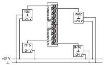
text_image
IN01 +24 V IN02 +24 V IN15 +24 V IN16 +24 V -24 V
text_image
Electrical schematic diagram showing connections between power supply and control panel with labeled terminalsConnections in multi-conductor technology, using Smart Elements for potential distribution

text_image
AXL SE PD16 24V AXL SE DI16/1 AXL SE PD16 GND IN01 +24 V IN16 +24 V
text_image
AXL SE DO16/1 AXL SE PD16 GND OUT01 OUT16You can use the following Smart Elements for potential distribution:
Table 8-1 Smart Elements for potential distribution
| Item no. Type Features | |
| 1337223 AXL SE PD16 24V 16 x 24 V (UP)2 fuses, 2 A each | |
| 1337224 AXL SE PD16 GND 16 x GND (UP) | |
| 1337225 AXL SE PD8/8 24V/GND 8 x 24 V (UP), 8 x GND (UP)1 fuse, 4 A | |

Detailed information on the Smart Elements for potential distribution can be found in the associated data sheets. There you will also find instructions for use and examples.
9 Diagnostic and status indicators
For quick local error diagnostics, the Smart Elements are provided with diagnostic and status indicators. They enable the localization of errors.
Figure 9-1 Diagnostic and status indicators

text_image
E E X ETable 9-1 Diagnostic and status indicators
| Identification in Figure 9-1 | Meaning Color | |
| E Error: diagnostics, both LEDs redundantly indicate diagnostics. Red | ||
| X Status indicator, depends on the Smart Element Green, yellow or red | ||
Diagnostics
The diagnostic indicators (E, red) provide information on the state of the Smart Element. If the red LEDs are off, the Smart Element is working correctly.
As LED E is provided twice, one LED E is always visible, no matter what the cable installation is.
Table 9-2 Diagnostic LED E
| Designation | Color Description Remedy | |||
| E Red Error | ||||
| Off No error | ||||
| Flashing (0.5 Hz) | Smart Element error | Replace the Smart Element. | ||
| Flashing (4 Hz) | Communication error | Check whether the Smart Element has been inserted correctly. | ||
| On I/O error | Possible causes:– I/O supply voltage not present– Short circuit or overload of an output– Wire break at an analog output– ... | Check the connected components and wiring. Remove the error. | ||
Status
The status indicators indicate the status of the relevant input or output and of the connected I/O device or of a supply voltage.

For information about the diagnostic and status indicators on a Smart Element and their meaning, please refer to the specific documentation.
Reporting diagnostics via PDI
The malfunctions indicated by the local diagnostic and status indicators are also mapped in PDI object 0018 _hex (DiagState).
Detailed information can be found in the data sheet for the Smart Element.
10 Process, parameter and diagnostic data
The Smart Element interface is used for the transmission of process data and parameter data.
10.1 Process data
Smart Elements have at least one byte of process data.
The AXL SE SC and AXL SE SC-A slot covers are an exception.
They have no process data (0 bytes) in all systems except for PROFIBUS.
Due to the system, they have 1 byte of input process data with PROFIBUS.
The significance of the data corresponds to the Motorola format (Big Endian).
The significance of the data bytes declines as the number goes up.

For the process data assignment and the assignment of the process data to the terminal points of a Smart Element, please refer to the specific data sheet.
10.2 Parameter and diagnostic data (PDI channel)
Parameter and diagnostic data as well as other information is transmitted via the PDI channel (PDI = Parameters, Diagnostics, and Information).
The PDI channel is used in addition to the process data channel for demand-oriented, acyclic transmission of parameter and diagnostic data as well as other information. Each Axioline Smart Element has this acyclic channel to be able to exchange acyclic data.
Via the PDI channel, you use read and write services to access the communication objects created in the Smart Element. These objects can be used, for example, to set measuring ranges, to specify the substitute value behavior of outputs in the event of a bus error, or to read I/O diagnostic details.

For detailed information on PDI objects, please refer to the UM EN AXL F SYS INST user manual.
10.3 Saving of parameters
Every Axioline Smart Element has parameters. They can be read or written or can be read and written. The parameters that can be written are saved every time a change is made.
In the device description file of each Smart Element, some of the parameters are defined as startup parameters.
Startup parameters (flash)
Startup parameters are stored retentively (in a non-volatile way, permanently) in the flash memory.
Startup parameters include the application object parameters, e.g., substitute value, filter time, etc. As soon as valid parameters are specified for these objects, they are stored retentively on the Smart Element.
Due to the storage technology used, parameters that are stored retentively can only be written for a specific number of times (100,000 up to 1,000,000 times, typically). They are not suitable for being changed cyclically.
A Smart Element only accesses the flash memory if retentively stored parameters are changed. This way, the flash is not “strained” in case of repeated writing operations of identical startup parameters.
However, if retentively stored data is changed from the application constantly, for example, the flash ages accordingly fast.
NOTE: Damage to the flash memory during cyclic write access
The flash memory is only designed for a limited number of write access operations.
- Therefore make sure that write access operations are not performed too often and, in particular, are not performed cyclically.
- Observe this behavior when programming function blocks.
Other parameters (RAM)
Other parameters are stored temporarily (in a volatile way) in the RAM.
11 Device replacement, device defects, and repairs
11.1 Device replacement
To replace a Smart Element, proceed as follows:
- Observe the safety notes for mounting and removal.
See Section 6.1, "Safety notes for mounting and removal".
- If necessary, disconnect the wiring.
See Section 7.6, "Removing cables from the terminal point".
- Replace the Smart Element in your application with a new Smart Element. See
- Section 6.4, "Removing Smart Elements"
- Section 6.3, "Mounting Smart Elements".
- Connect the I/O devices, if necessary.
See
- Section 7.4, "Connecting unshielded cables"
- Section 7.5, "Connecting shielded cables".
Observe the device type and version
The new Smart Element must meet the following requirements:
- Same device type
– Same or later version of the hardware and firmware
11.2 Device defects and repairs
Do not open the housing
Repairs may only be carried out by Phoenix Contact. Do not open the housing. If the housing is opened, the function of the device can no longer be ensured.
Defective devices Please contact Phoenix Contact.
12 Maintenance, decommissioning, and disposal
12.1 Maintenance
Smart Elements are maintenance-free.
12.2 Decommissioning and disposal
Carry out decommissioning in accordance with the requirements of the machine or system manufacturer.
When decommissioning the system or parts of the system, ensure the following for the devices used.
The device continues to be used as intended:
- Observe the storage and transport requirements.
See Section "Transport, storage, and unpacking" on page 17.
The device is not used anymore:
Device disposal
- Do not dispose of the device with household waste; it should instead be disposed of in accordance with the currently applicable national regulations.
Packaging disposal
- Dispose of packaging materials that are no longer needed (cardboard packaging, paper, bubble wrap sheets, tubular bags, etc.) with household waste in accordance with the currently applicable national regulations.
13 Technical data and ordering data

Observe additional documentation
- When using Smart Elements, also observe the technical data of the system in which you use the Smart Elements.
- For safety applications, refer to the documentation for the Smart Elements used with safety function.

The following values are default values.
- For deviating values, please refer to the documentation for the Smart Element used.
13.1 Technical data
| General data (default values; for deviations see documentation for the Smart Element used) | |
| Ambient temperature (operation) -25°C ... +60°C | |
| Ambient temperature (storage/transport) -40°C ... +85°C | |
| Permissible humidity (operation/storage/transport) | 5% ... 95% (non-condensing) |
| Permissible air pressure (operation/storage/transport) | 5% ... 95% (non-condensing) |
| Air pressure (operation) | 70 kPa ... 106 kPa (up to 3000 m above mean sea level) |
| Air pressure (storage/transport) | 70 kPa ... 106 kPa (up to 3000 m above mean sea level) |
| Degree of protection IP20 | |
| Protection class Extra-low voltage: III (IEC 61140, EN 61140, VDE 0140-1) | |
| Low voltage: II (IEC 61140, EN 61140, VDE 0140-1, mounted in an adequate housing with at least IP54 protection) | |
| Overvoltage category | Extra-low voltage: II (IEC 60664-1, EN 60664-1) |
| Low voltage: III (IEC 61010-2-201, EN 61010-2-201) | |
| Pollution degree | Extra-low voltage: 2 (IEC 60664-1, EN 60664-1) |
| Low voltage: 2 (IEC 61010-2-201, EN 61010-2-201) | |
| Air clearances and creepage distances | Extra-low voltage: in accordance with IEC 60664-1, EN 60664-1 |
| Low voltage: in accordance with IEC 61010-2-201, EN 61010-2-201 | |
| Housing material | Plastic |

Do not use Smart Elements in an atmosphere that contains corrosive gas.
Interface: Smart Element interface
Number 1
Connection method Card edge connector
Number of insertion cycles 10
Function Data transmission
Communications power supply of the Smart Elements I/O power supply of the Smart Elements Connection to functional ground
Current consumption See documentation for the system in which the
Smart Elements are used
Connection data: I/O

For electrical and/or thermal reasons, it may not be possible to use the minimum conductor cross-sections specified here for certain Smart Elements. Therefore, always observe the information in the documentation specific to the Smart Element.
Connection method Push-in connection
Maximum current carrying capacity of the contacts 8 A
Rigid and flexible conductors without ferrules or with single ferrules
Conductor cross-section, rigid/flexible
0.25mm^2 ... 1.5mm^2 /0.25mm^2 ... 1.5mm^2
Conductor cross-section [AWG] 24 ... 16
Stripping lengths 8 mm
Two conductors with the same cross-section, flexible with TWIN ferrule and plastic collar
Conductor cross-section 0.5 mm ^2 per conductor
Conductor cross-section [AWG] 20
Stripping lengths 10 mm

Please observe the information on conductor cross-sections and stripping lengths in Section “Conductor cross-sections, stripping and insertion lengths” on page 23.
Communications power supply of the Smart Element ( U_SE )
Remark
The communications power supply is provided via the Smart Element interface by the system in which you use the Smart Element.
Current consumption
See data sheet for the system in which you use the Smart Element
Power consumption
See data sheet for the system in which you use the Smart Element
24 V I/O supply ( U_P )
Nominal voltage 24 V DC (using card edge connector)
Maximum permissible voltage range
Current consumption See data sheet for the Smart Element
Power consumption See data sheet for the Smart Element
19.2 V DC ... 30.0 V DC (all tolerances included, ripple included)
6 A, maximum, observe possible limitations of the system in which you use the Smart Element.
Electrically isolated areas
See data sheet for the Smart Element
Test voltages (default values for the 24 V area; for deviations and the low voltage area, see documentation specific to the Smart Element)
Isolating distance Test voltage
Communications power supply/24 V supply (I/O)
500 V AC, 50 Hz, 1 min
Communications power supply/functional ground
500 V AC, 50 Hz, 1 min
24 V supply (I/O)/functional ground
500 V AC, 50 Hz, 1 min
Mechanical tests (default values; for deviations, see documentation specific to the Smart Element)
Vibration resistance in accordance with EN 60068-2-6/IEC 60068-2-6
5g
Shock testing in accordance with EN 60068-2-27/IEC 60068-2-27
30g
Bump endurance test in accordance with EN 60068-2-27/IEC 60068-2-27
10g
Conformance with EMC Directive 2004/108/EC
Immunity test in accordance with EN 61000-6-2/IEC 61000-6-2
See data sheet for the Smart Element used
Noise emission test in accordance with EN 61000-6-4/IEC 61000-6-4
Class A
Voltage dips and interruptions of I/O supply U_p
See system in which you use the Smart Element.
Approvals
For the latest approvals, please visit phoenixcontact.net/products.
Manufacturer's declarations
The latest manufacturer's declarations can be found at phoenixcontact.net/products.
13.2 Ordering data

The complete product catalog is available in electronic form at phoenixcontact.net/products.
Ordering data for Axioline Smart Elements
Ordering data for the Axioline Smart Elements is available on the Internet at phoenixcontact.net/products.
Ordering data for accessories
Description Type Item No. Pcs./Pkt.
Tools
| Screwdriver, bladed, VDE-insulated, size: 0.4 mm x 2.5 mm x 80 mm, 2-component handle, with non-slip grip |
| Crimping pliers, for ferrules without insulating collar in accordance with DIN 46228 Part 1 and ferrules with insulating collar in accordance with DIN 46228 Part 4, 0.25 mm^2 ... 6.0 mm^2 , lateral entry, trapezoidal crimp |
SZS 0,4X2,5 VDE 1205037 1
CRIMPFOX 6 1212034 1
| Crimping pliers, type of contact: insulated and uninsulated ferrules, standards/regulations: DIN 46228-1, DIN 46228-4, cross-section, minimum: 0.14 mm^2 ,cross-section, maximum: 10 mm^2 ,for TWIN ferrules up to 2 mm^2 × 4 mm^2 , automatic cross-section adjustment, rotating dies, lateral and front entry, crimping: trapezoidal crimp, black/green |
CRIMPFOX DUO 10 1031721 1
| Crimping pliers, type of contact: insulated and uninsulated ferrules, standards/regulations: DIN 46228-1,DIN 46228-4, cross-section, minimum: 0.14 mm^2 , cross-section, maximum: 10 mm^2 , for TWIN ferrules up to 2 mm^2 × 4 mm^2 ,automatic cross-section adjustment, rotating dies, lateral and front entry, crimping: trapezoidal crimp, black/green |
CRIMPFOX 10T-F 1134913 1
Test probes
Test probe, blue MPS-MT 1-S4-B 1974614 50
| Test probe, red |
| Test probe, red |
| MPS-MT 1-S4-B RD | 1982800 50 |
| MPS-MT 1-S4-B RD VPE1 | 1020292 1 |
Marking material
| Label, continuous, cassette, transparent with black imprint, mounting type: adhesive, can be marked with THERMO-FOX |
| MM-TML (EX4,2)R C1 | 0803979 1 |
| TR/BK |
| Marker strip, roll, white, unmarked, can be marked with: THERMOMARK ROLL 2.0, THERMOMARK ROLL, THERMOMARK ROLL X1, THERMOMARK ROLLMASTER 300/600, THERMOMARK X1.2, mounting type: adhesive, for terminal block width: 5 mm, lettering field size: continuous x 5 mm |
| SK 5,0 WH:REEL | 0805221 1 |
| Markers, 24-section, unmarked, can be marked with THERMOMARK CARD and BLUEMARK, color: white |
| UM6M-TM (5X12) | 0830928 10 |
| Description | Type | Item No. | Pcs./Pkt. |
| Markers, sheet, white, unmarked, can be marked with: THERMOMARK CARD, THERMOMARK CARD 2.0, THERMOMARK PRIME, BLUEMARK ID, BLUEMARK ID COLOR, TOPMARK LASER, TOPMARK NEO, mounting type: snap into a high marker groove, for terminal block width: 5.2 mm, lettering field size: 4.17 mm x 11.3 mm | UCT6M-TM 5 0830756 10 | ||
| Ferrules | |||
| Ferrules with insulating collar (plastic collar), in accordance with DIN 46228-4; sleeve length: 8 mm | AI ... See “Marking systems, tools, and mounting material” catalog | ||
| Cross-section 0.5 mm^2 | AI 0,5 - 8 WH -1000 3200881 1000 | ||
| Cross-section 0.75 mm^2 | AI 0,75- 8 GY -1000 3200894 1000 | ||
| Cross-section 1.0 mm^2 | AI 1 - 8 RD -1000 3200904 1000 | ||
| Ferrules without insulating collar (plastic collar), in accordance with DIN 46228-1; length: 8 mm | A ... See “Marking systems, tools, and mounting material” catalog | ||
| Cross-section 0.5 mm^2 | A 0,5 - 8 3202481 1000 | ||
| Cross-section 0.75 mm^2 | A 0,75- 8 3202504 1000 | ||
| Cross-section 1.0 mm^2 | A 1 - 8 3202517 1000 | ||
| TWIN ferrules with insulating collar (plastic collar), in accordance with DIN 46228-4; sleeve length: 10 mm | AI-TWIN ... See “Marking systems, tools, and mounting material” catalog | ||
| Cross-section 0.5 mm^2 | AI-TWIN 2X 0,5-10 WH 3203309 100 | ||
Ordering data for documentation

The documentation can be downloaded at phoenixcontact.net/products.
Make sure you always use the latest documentation.
A Technical appendix: altitudes above 3000 m
Use of Axioline Smart Elements at altitudes above 3000 meters
This section applies to Smart Elements that are operated with a DC voltage of <60 V DC.

WARNING: Dangerous contact voltage. Loss of the safety function.
This section does not apply to the following Smart Elements or applications:
- Smart Elements that are not operated with PELV (protective extra-low voltage) (e.g., 230 V)
- Smart Elements with safety functions (e.g., SafetyBridge, PROFIsafe)
- Use of a safe signal path
In these cases, consider the individual Smart Element or application separately.
The Smart Elements are approved for use at altitudes up to 3000 m above mean sea level, see “Technical data” on page 37.
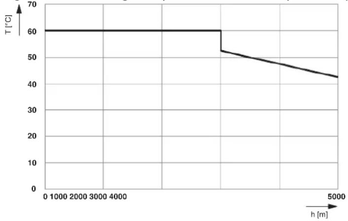
The maximum permissible ambient temperature decreases at altitudes above this level. Therefore, keep temperature derating in mind when using the Smart Elements at altitudes above 3000 m up to 5000 m.
Figure A-1 Derating of the permissible ambient temperature depending on the altitude
line
| h [m] | T [°C] | |---|---| | 0 | 60 | | 5000 | 60 | | 10000 | 60 | | 2000 | 60 | | 3000 | 60 | | 4000 | 60 | | 5000 | 52 | | 6000 | 51 | | 7000 | 50 | | 8000 | 49 | | 9000 | 48 | | 10000 | 47 | | 11000 | 46 | | 12000 | 45 | | 13000 | 44 | | 14000 | 43 | The chart displays a stepwise decreasing trend in temperature as height increases from 0 to 5000 meters. The x-axis represents height in meters and the y-axis represents temperature in degrees Celsius. There is no label for the data series.Key:
T [°C] Maximum ambient temperature (operation) in °C h [m] Altitude in m
B Index
A
Altitude above 3000 m 42
Application note 8
Approvals.... 13
C
Cable connection method 38
CABLE-FLK14/AXIO/OE/0,14/ 24
Checking the delivery.... 17
Color 15
Conductor connection.... 13
Conductor cross-section 23, 38
Connecting cables Shielded .... 27 Unshielded .... 26
Connecting shielded cables.... 27
Connecting unshielded cables.... 26
Connection data.... 23, 38
D
Data sheet....7
Data transfer 38
Diagnostic elements Marking .... 31
Diagnostic indicators.... 31
Diagnostics 12,31
Dimensions 11
Downloading the documentation....8
E
Equipment identification.... 16
Error Diagnostics.... 31
Extra-low voltage 12
F
Ferrule.... 23
Function 11, 13, 15
Function extension.... 14
G
Grounding 12
H
Housing versions 10
|
Indication elements.... 31
Marking 15
Item designations.... 13
L
Low voltage.... 12
Low voltage range.... 19
M
Maintenance 35, 36
Marking Equipment identification.... 16 Indication elements.... 15 Terminal points.... 15
Marking material 16
Mounting.... 12
Mounting location.... 12
Mounting position.... 20 Preferred .... 20
P
Packing slip.... 7
PDI channel 33
Printing on the Smart Element.... 7
Product group 13
Protective extra-low voltage.... 12
Q
Qualification.... 18
Quick-start guide.... 8
R
Removal.... 12
Replace.... 35
S
Shielding 12
Connecting the shield.... 27
Spring lever.... 25
Status.... 32
Status indicators 31
Storage 17
Stripping lengths 23, 38
Structure of a Smart Element 10
Supply voltage
Communications power.... 12
I/O 12
T
Terminal points
Marking 15
Touch connection 25
Transport 17
Tubular bag printing 7
TWIN ferrule....23
TWIN ferrules.... 24
U
Unpacking....17
User manual....7
V
Voltage ranges.... 12
A Revision history
Table A-1 Revision history
| Revision Date | Contents | ||
| 00 2019-11-13 | First publication | ||
| 01 2020-08-26 | Section 4.3, Section 10.1 Additions: AXL SE SC | ||
| 02 2020-11-30 | Entire document Additions: | – New Smart Elements– Low voltage range– Safety notes– TWIN ferrules | |
| 03 2021-04-03 | Section 7.2 Table 7-2: | TWIN ferrules added | |
| CABLE-FLK14/AXIO/OE/0,14/... added | |||
| Section 7.5 Addition: Please note in general | |||
| Section 8.3 New: Smart Elements with 1-conductor technology | |||
| Section 13.1 IEC added | |||
| Appendix A Addition in the warning note | |||
Please observe the following notes
General Terms and Conditions of use for technical documentation
Phoenix Contact reserves the right to alter, correct, and/or improve the technical documentation and the products described in the technical documentation at its own discretion and without giving prior notice, insofar as this is reasonable for the user. The same applies to any technical changes that serve the purpose of technical progress.
The receipt of technical documentation (in particular user documentation) does not constitute any further duty on the part of Phoenix Contact to furnish information on modifications to products and/or technical documentation. You are responsible to verify the suitability and intended use of the products in your specific application, in particular with regard to observing the applicable standards and regulations. All information made available in the technical data is supplied without any accompanying guarantee, whether expressly mentioned, implied or tacitly assumed.
In general, the provisions of the current General Terms and Conditions of Phoenix Contact apply exclusively, in particular as concerns any warranty liability.
This manual, including all illustrations contained herein, is copyright protected. Any changes to the contents or the publication of extracts of this document are prohibited.
Phoenix Contact reserves the right to register its own intellectual property rights for the product identifications of Phoenix Contact products that are used here. Registration of such intellectual property rights by third parties is prohibited.
Other product identifications may be afforded legal protection, even where they may not be indicated as such.
How to contact us
Internet
Up-to-date information on Phoenix Contact products and our Terms and Conditions can be found on the Internet at: phoenixcontact.com
Make sure you always use the latest documentation. It can be downloaded at: phoenixcontact.net/products
Subsidiaries
If there are any problems that cannot be solved using the documentation, please contact your Phoenix Contact subsidiary. Subsidiary contact information is available at phoenixcontact.com.
Published by Phoenix Contact GmbH & Co. KG
Should you have any suggestions or recommendations for improvement of the contents and layout of our manuals, please send your comments to: tecdoc@phoenixcontact.com
Phoenix Contact GmbH & Co. KG
Flachsmarktstraße 8
32825 Blomberg, Germany
Phone: +49 5235 3-00
Fax: +49 5235 3-41200
Email: info@phoenixcontact.com
phoenixcontact.com