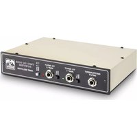
Grand Audition MKII - Receiver Palmer - Free user manual and instructions
Find the device manual for free Grand Audition MKII Palmer in PDF.
| Product type | 19" Professional Speaker Switching System |
| Model | Grand Audition MKII (PGAMK2) |
| Brand | Palmer (Adam Hall) |
| Dimensions (W x H x D) | 482.6 x 89.4 x 282.3 mm |
| Weight | 5.6 kg |
| Power supply | 100-240 V AC, 50-60 Hz, 65 W max, fuse T 630 mA 250 V |
| Rack format | 19" / 2 U |
| Number of inputs | 2 balanced XLR (front/rear, parallel) |
| Number of outputs | 24 + 2 balanced XLR outputs (16 speaker + 8 subwoofer + 2 link) Speaker outputs: 16 channels (configurable in stereo or mono) Subwoofer outputs: 8 mono channels |
| Built-in audio player | USB-A port for USB stick, supported formats: mp3, ogg, flac, wav, aiff, FAT32 file system |
| Remote control | Via browser application (wired Ethernet or Wi-Fi via router) |
| Switching modes | SINGLE (only one output at a time) or MULTI (multiple outputs simultaneously) |
| Channel gain | +/-14 dB per output |
| Master gain | -80 dB to 0 dB |
| Input sensitivity | 0 dB, -6 dB, +6 dB, +20 dB (adjustable) |
| Frequency response | 20 Hz to 20 kHz (+0.1/-0.2 dB for XLR inputs) |
| Signal-to-noise ratio | >109 dB (A-weighted, Unity-Gain) |
| Dynamic range | >126 dB (XLR inputs, A-weighted) |
| Max. output level | +21 dBu (balanced, load >2 kohms) |
| Cascading | Up to 3 units, controlled from the same application |
| Maintenance and cleaning | Dry cloth; do not open; repairs by qualified personnel |
| Safety | Do not expose to water, do not block ventilation slots, follow voltage and grounding instructions |
| Spare parts and repairability | Fuse of same type and rating; user can only replace the fuse; contact authorized center for any other |
| General information | Manufacturer warranty on the Adam Hall website; disposal in accordance with the WEEE directive |
Frequently Asked Questions - Grand Audition MKII Palmer
User questions about Grand Audition MKII Palmer
0 question about this device. Answer the ones you know or ask your own.
Ask a new question about this device
Download the instructions for your Receiver in PDF format for free! Find your manual Grand Audition MKII - Palmer and take your electronic device back in hand. On this page are published all the documents necessary for the use of your device. Grand Audition MKII by Palmer.
USER MANUAL Grand Audition MKII Palmer
be true to your sound
natural_image
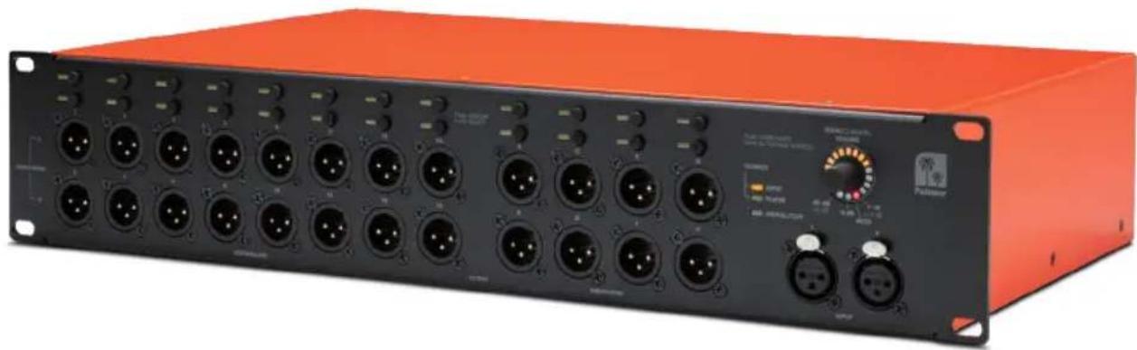
Orange electronic device with multiple black connectors and ports, no visible text or symbols on the main body.GRAND AUDITION MKII
24-CHANNEL LOUDSPEAKER SWITCHING SYSTEM PGAMKII
CONTENTS / INHALTSVERZEICHNIS / CONTENU / CONTENIDO / TREŚĆ / CONTENUTO
ENGLISH
SAFETY INFORMATION 3
INTRODUCTION 5
CABLING/WIRING AND SETUP 5
CABLING/WIRING EXAMPLE 6
CONNECTIONS, CONTROL, AND DISPLAY ELEMENTS 6
APP CONTROL 8
WIRED CONNECTION VIA ETHERNET 9
WIRELESS CONNECTION VIA WLAN 10
GRAND AUDITION MK2 CASCADING 11
BROWSER-BASED CONTROL APP 12
MAIN - MAIN MUTE - SELECT MODE - AUDIO PLAYER 12
DEVICES 14
CHANNELS 15
PLAYER 16
VOLUMES 18
USER 19
SIGNAL FLOW DIAGRAM 21
TECHNICAL SPECIFICATIONS 22
MANUFACTURER'S DECLARATIONS 24
DEUTSCH
We have designed this product to operate reliably over many years. Palmer® stands for this with its name and many years of experience as a manufacturer of high-quality audio products. Please read this User's Manual carefully, so that you can begin making optimum use of your Palmer® product quickly.
You can find more information about Palmer® at our Internet site www.palmer-germany.com.
SAFETY INFORMATION
- Please read these instructions carefully.
- Keep all information and instructions in a safe place.
- Follow the instructions.
- Observe all safety warnings. Never remove safety warnings or other information from the equipment.
- Use the equipment only in the intended manner and for the intended purpose.
- Use only sufficiently stable and compatible stands and/or mounts (for fixed installations). Make certain that wall mounts are properly installed and secured. Make certain that the equipment is installed securely and cannot fall down.
- During installation, observe the applicable safety regulations for your country.
- Never install and operate the equipment near radiators, heat registers, ovens or other sources of heat. Make certain that the equipment is always installed so that is cooled sufficiently and cannot overheat.
- Never place sources of ignition, e.g., burning candles, on the equipment.
- Ventilation slits must not be blocked.
- Keep a minimum distance of 20 cm around and above the device.
- Do not use this equipment in the immediate vicinity of water (does not apply to special outdoor equipment - in this case, observe the special instructions noted below. Do not expose this equipment to flammable materials, fluids or gases. Avoid direct sunlight!
- Make certain that dripping or splashed water cannot enter the equipment. Do not place containers filled with liquids, such as vases or drinking vessels, on the equipment.
- Make certain that objects cannot fall into the device.
- Use this equipment only with the accessories recommended and intended by the manufacturer.
- Do not open or modify this equipment.
- After connecting the equipment, check all cables in order to prevent damage or accidents, e.g., due to tripping hazards.
- During transport, make certain that the equipment cannot fall down and possibly cause property damage and personal injuries.
- If your equipment is no longer functioning properly, if fluids or objects have gotten inside the equipment or if it has been damaged in anot her way, switch it off immediately and unplug it from the mains outlet (if it is a powered device). This equipment may only be repaired by authorized, qualified personnel.
- Clean the equipment using a dry cloth.
- Comply with all applicable disposal laws in your country. During disposal of packaging, please separate plastic and paper/cardboard.
- Plastic bags must be kept out of reach of children.
- Please note that changes or modifications not expressly approved by the party responsible for compliance could void the user's authority to operate the equipment.
FOR EQUIPMENT THAT CONNECTS TO THE POWER MAINS
-
CAUTION: If the power cord of the device is equipped with an earthing contact, then it must be connected to an outlet with a protective ground. Never deactivate the protective ground of a power cord.
-
If the equipment has been exposed to strong fluctuations in temperature (for example, after transport), do not switch it on immediately. Moisture and condensation could damage the equipment. Do not switch on the equipment until it has reached room temperature.
-
Before connecting the equipment to the power outlet, first verify that the mains voltage and frequency match the values specified on the equipment. If the equipment has a voltage selection switch, connect the equipment to the power outlet only if the equipment values and the mains power values match. If the included power cord or power adapter does not fit in your wall outlet, contact your electrician.
-
Do not step on the power cord. Make certain that the power cable does not become kinked, especially at the mains outlet and/or power adapter and the equipment connector.
-
When connecting the equipment, make certain that the power cord or power adapter is always freely accessible. Always disconnect the equipment from the power supply if the equipment is not in use or if you want to clean the equipment. Always unplug the power cord and power adapter from the power outlet at the plug or adapter and not by pulling on the cord. Never touch the power cord and power adapter with wet hands.
-
Whenever possible, avoid switching the equipment on and off in quick succession because otherwise this can shorten the useful life of the equipment.
- IMPORTANT INFORMATION: Replace fuses only with fuses of the same type and rating. If a fuse blows repeatedly, please contact an authorised service centre.
- To disconnect the equipment from the power mains completely, unplug the power cord or power adapter from the power outlet.
- If your device is equipped with a Volex power connector, the mating Volex equipment connector must be unlocked before it can be removed. However, this also means that the equipment can slide and fall down if the power cable is pulled, which can lead to personal injuries and/or other damage. For this reason, always be careful when laying cables.
- Unplug the power cord and power adapter from the power outlet if there is a risk of a lightning strike or before extended periods of disuse.
- The appliance is not to be used by persons (including children) with reduced physical, sensory or mental capabilities, or lack of experience and knowledge.
- Children must be instructed not to play with the device.
- If the power cord of the device is damaged, do not use the device. The power cord must be replaced by an adequate cable or assembly from an authorized service center.

CAUTION:
To reduce the risk of electric shock, do not remove cover (or back). There are no user serviceable parts inside. Maintenance and repairs should be exclusively carried out by qualified service personnel.

The warning triangle with lightning symbol indicates dangerous uninsulated voltage inside the unit, which may cause an electrical shock.

The warning triangle with exclamation mark indicates important operating and maintenance instructions.

Warning! This device is designed for use below 2000 metres in altitude.

Warning! This product is not intended for use in tropical climates.
CAUTION! HIGH VOLUMES IN AUDIO PRODUCTS!
This device is meant for professional use. Therefore, commercial use of this equipment is subject to the respectively applicable national accident prevention rules and regulations. As a manufacturer, Adam Hall is obligated to notify you formally about the existence of potential health risks.
Hearing damage due to high volume and prolonged exposure: When in use, this product is capable of producing high sound-pressure levels (SPL) that can lead to irreversible hearing damage in performers, employees, and audience members. For this reason, avoid prolonged exposure to volumes in excess of 90 dB.
NOTE: This equipment has been tested and found to comply with the limits for a Class B digital device, pursuant to Part 15 of the FCC Rules. These limits are designed to provide reasonable protection against harmful interference in a residential installation. This equipment generates, uses and can radiate radio frequency energy and, if not installed and used in accordance with the instructions, may cause harmful interference to radio communications. However, there is no guarantee that interference will not occur in a particular installation. If this equipment does cause harmful interference to radio or television reception, which can be determined by turning the equipment off and on, the user is encouraged to try to correct the interference by one or more of the following measures:
- Reorient or relocate the receiving antenna.
- Increase the separation between the equipment and receiver.
- Connect the equipment into an outlet on a circuit different from that to which the receiver is connected.
- Consult the dealer or an experienced radio/TV technician for help.
INTRODUCTION
The 19-inch Grand Audition MK2 loudspeaker switching system by Palmer is the perfect tool for controlling up to 16 individual loudspeakers or eight loudspeaker pairs plus up to eight subwoofers. It is equipped with balanced stereo input with XLR connectors and an internal music player with a USB port. The system can be controlled either manually on the device itself or remotely with a browser-based app. Latency-free audio playback without sound coloration is enabled by analog signal routing.
PROPERTIES
- Intuitive browser-based wireless remote control
• 24 switchable balanced line outputs - Individual volume control on all outputs
- Multi-output mode – simple splitting function
• Mono and stereo output modes
• High-quality analog signal path
• Latency- and noise-free channel switching - Integrated media player and stereo XLR line input connectors
- Expandable by up to two additional units
SCOPE OF DELIVERY:
Grand Audition MK2, power cable, user manual
CABLING/WIRING AND SETUP
Before putting the device into operation, make sure to observe the technical specifications for all components, such as the maximum output level of auxiliary devices, the maximum input level of the loudspeaker switching system, and connected powered loudspeakers or power amplifiers! In case of uncertainty, consult an experienced audio technician. Use high-quality and, if possible, balanced cables for cabling/wiring. In the following, you will find information about how to cable/wire and set up the loudspeaker switching system with powered loudspeakers. This procedure can also be used for cabling/wiring and setting up a power amplifier and unpowered loudspeakers.
- Before you start cabling/wiring, turn off any devices to be connected to the loudspeaker switching system and set the volume of all devices to minimum.
- After the cabling/wiring is completed, turn on the connected loudspeakers and power amplifiers as the last devices.
- Adjust and match the volume of the connected loudspeakers to each other to prevent sudden spikes in volume when switching the speaker outputs.
CABLING/WIRING EXAMPLE

text_image
Diagram of a audio equipment setup with speaker, amplifier, and display units connected to a control panel with labeled buttons and indicators.Music player
CONNECTIONS, CONTROL, AND DISPLAY ELEMENTS

text_image
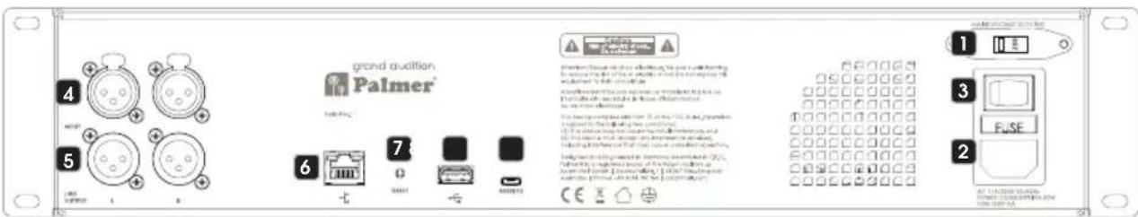
grand audition Palmer® 1 2 3 4 5 6 7 8 9 10 11 12 13 14 15 16 17 18 19 20 21 22 23 24 25 26 27 28 29 30 31 32 33 34 35 36 37 38 39 40 41 42 43 44 45 46 47 48 49 50 51 52 53 54 55 56 57 58 59 60 61 62 63 64 65 66 67 68 69 70 71 72 73 74 75 76 77 78 79 80 81 82 83 84 85 86 87 88 89 90 91 92 93 94 95 96 97 98 99 1001 LINE VOLTAGE SELECTOR 115/230
Check the switch for setting the operating voltage before connecting the device to the power supply. The line voltage of your energy supply and the operating voltage of the device must be the same. If they are different, put the switch in the position corresponding to your energy supply's line voltage (115 V or 230 V).
2 POWER SOCKET AND FUSE HOLDER
IEC power socket with integrated fuse holder. A suitable power cable is included in delivery. IMPORTANT NOTE: Only replace the fuse with a fuse of the same type. Please observe the inscription on the housing, and use a fuse that corresponds to your energy supply's power supply voltage. If a fuse trips repeatedly, please contact an authorized service center.
3 ON/OFF SWITCH
Switch on the device before you switch on the connected powered loudspeakers and power amplifiers, and switch it off after you have switched off the connected powered loudspeakers and power amplifiers.
4 INPUT L/R
Balanced stereo line input with female 3-pin XLR connectors. The line inputs on the front and back are wired in parallel. Alternate using the inputs (either front or back).
5 LINK OUTPUT L/R
Balanced stereo line output with male 3-pin XLR connectors. When up to three devices are cascaded, use the line output to transmit the input signal.
6 NETWORK CONNECTOR
Network connector for controlling the device with the browser-based app (minimum display resolution: 1024 × 768 ). For wireless connection, a WLAN router with a connection for each loudspeaker switching device is required. The WLAN router is not included in the scope of delivery.
7 RESET
The reset button is recessed to prevent accidental operation. Briefly press the button to reset the network settings. To factory reset the device, press the button until the device restarts (MAIN/CHANNEL VOLUME LED ring on the front shows a rotating animation.) The device's firmware version remains unchanged. Browser-based app: A factory reset will delete all previously added users, reset the username (USER) to admin, and also reset the corresponding password to admin.
8 USB PORT
USB connection with type A socket for connecting a USB storage medium (USB stick). Audio files stored on the USB stick can be played with the internal audio player that is controlled with the browser-based app (a direct Ethernet connection or a WLAN router connection is required; supported audio formats: mp3, ogg, flac, wav, alff; recommended file system: FAT32).
9 SERVICE
Micro USB port. Only for servicing purposes.

text_image
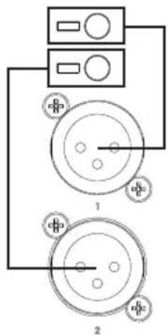
13 10 15 11 12 Polarizer RIPUT PLATIN SPRINGA/SP Polarizer 14 15 L INPUT S10 LOUDSPEAKER OUTPUT 1-16
Balanced line outputs for connecting powered loudspeakers and power amplifiers (male 3-pin XLR connectors). The web-based app can be used to configure the outputs in pairs in stereo (Output 1/2, 3/4, etc.) or individually in mono. In the mono configuration, a stereo signal that is fed to the line input or is that reproduced by the internal player is automatically mono summed.
11 OUTPUT SUBWOOFER A-H
Balanced line outputs for connecting powered subwoofers and power amplifiers (male 3-pin XLR connectors). A stereo signal that is reproduced by the internal player or that is fed to the line input is automatically mono summed.
12 INPUT L/R
Balanced stereo line input with female 3-pin XLR connectors. The line inputs on the front and back are wired in parallel. Alternate using the inputs (either front or back).
13 LOUDSPEAKER AND SUBWOOFER OPERATING BUTTONS
Switch output ON/OFF: The line outputs are switched on and off with the operating buttons. Briefly press the corresponding button to do this; in the stereo configuration, both the upper or lower button can be used. If an output is switched off, the corresponding LED will turn off; if the output is switched on, the LED illuminates permanently. Adjusting the volume: To select the line outputs for adjusting the volume, press and hold the corresponding button until the corresponding LED flashes. All other line outputs are automatically switched off. You can then turn the push-button rotary encoder No. 14 to adjust the volume of the selected line output as desired. The LED ring shows the setting (-14 dB to +14 dB). The top three LEDs of the LED ring and the 0 dB LED illuminate at 0 dB gain A. Now briefly press the button for the line output which was just changed to exit the volume setting selection. The LED will stop flashing. The assignment of buttons, LEDs, and line outputs can be found in the adjacent figure.
14 MAIN/CHANNEL VOLUME
Multifunction push-button rotary encoder and LED ring.
MAIN VOLUME: Turn the encoder clockwise to increase the main volume and counterclockwise to decrease it. The LED ring shows the setting (-80 dB to 0 dB). The bottom LED 0 dB display illuminates at 0 dB gain A. A detailed description of how to adjust the volume for the line outputs is provided in Point 13 Adjusting the volume.
Mute all outputs (MAIN MUTE): Briefly press the encoder to mute all LOUDSPEAKER and SUBWOOFER line outputs; briefly press the encoder again to unmute. When muted, the red MUTE LED in the LED ring B is illuminated. The MUTE LED turns off once mute is deactivated.
TOGGLE SOURCE: Press and hold the encoder for approx. 2 seconds to switch between the INPUT und PLAYER signal sources. The corresponding LED C shows which of the two signal sources is activated.
text_image
Diagram showing two circular components connected to a control panel with labeled pins and polarity indicators
text_image
Push. MAIN MUTE Hold 2s: TOGGLE SOURCE SOURCE C INPUT PLAYER SIGNAL/CLIP MAIN/CHANNEL VOLUME -80 dB -14 dB 0 dB 0 dB +14 dB A MUTE B 15 1415 SIGNAL/CLIP
Bicolor multifunction LED display.
INPUT line input: To prevent the input level of the INPUT line input from being clipped by an external auxiliary device's audio signal, first switch off all OUTPUT LOUDSPEAKER and SUBWOOFER outputs (see Point 13). If there is a signal and the LED does not illuminate, the input level is not being clipped, if the LED illuminates red briefly, or if it illuminates red permanently, the auxiliary device's output level must either be reduced or the input gain must be set to a lower value using the web-based app.
OUTPUT LOUDSPEAKER and SUBWOOFER line outputs: If a signal is fed into one or more line outputs, the LED illuminates green; if an output is being clipped by an excessively high signal level, the LED illuminates red. Reduce the corresponding line output's output level as described in Point 13 or use the web-based app to adjust the setting.
APP CONTROL
In principle, it's possible to establish a connection to the Grand Audition MK2 with any Ethernet- or WLAN-capable terminal device. The operating system used is of secondary importance since the Grand Audition MK2 is controlled using a browser. Windows, Apple, and Linux operating systems, and tablets running on iOS and Android are suitable. Chrome, Safari, and Firefox browsers are recommended. Your computer or tablet should have a min. screen resolution of 1024 x 768 pixels; use the display in landscape format. Smartphones are not suitable for controlling the app due to the small display size.
WIRED CONNECTION VIA ETHERNET
To establish a wired connection, use your computer's Ethernet interface to directly connect to the Grand Audition MK2's Ethernet interface with an Ethernet cable (min. CAT5e). Switch on the Grand Audition MK2. In your computer's system settings under Properties of Internet Protocol Version 4 (TCP/IPv4), manually enter the IP address 192.168.2.1 and the subnet mask 255.255.255.0 and then confirm the entered data (the values are entered in a similar manner in the different operating systems; see example figures provided below).
WINDOWS

text_image
Editing Wired connection 1 Connection name: Wired connection 1 General: Ethernet 802.1x Security DCB: IPv4 Settings IPv6 Settings Method: Manual Addresses Address Netmask Gateway Add 192.168.2.1 255.255.255.0 Delete DNS servers: Search domains: DHCP client ID: Require IPv4 addressing for this connection to complete Routes... Cancel SaveThese settings are required the first time the connection is set up because the Grand Audition MK2's IP address and subnet mask are set by default to 192.168.2.99 and 255.255.255.0 and the value under IPv4 must be in the defined address space. The settings can be subsequently changed as required (see Grand Audition Control App: DEVICES, Point 4 Network).
Enter the IP address 192.168.2.99 into your browser's address line and press ENTER (←) to confirm. The Grand Audition's control app will open and show the LOGIN window. Tip: Bookmark this address in your browser.

text_image
Giant Audition Palmer® IP Address 192.168.2.99WIRELESS CONNECTION VIA WLAN
A WLAN router, which is configured with a browser-based app, is required to establish a wireless connection to the Grand Audition MK2. Establish a WLAN connection by connecting your tablet or computer to the WLAN router, enter the address in your browser's address line to open the configuration app, and press ENTER (←) to confirm. Follow the information provided in your WLAN router's operating instructions. Under Network and LAN, enter the IP address 192.168.2.1 and the subnet mask 255.255.255.0 and save the entered data (see the example figure below).
| Status | LAN Settings | |
| Quick Setup | ||
| Operation Mode | ||
| Network | ||
| - WAN | MAC Address: | 192.168.2.1 |
| - LAN | IP Address: | |
| - IPTV | ||
| - MAC Clone | Subnet Mask: | 255.255.255.0 |
| Dual Band Selection | ||
These settings are required the first time the connection is set up because the Grand Audition MK2's IP address and subnet mask are set by default to 192.168.2.99 and 255.255.255.0 and the value in the WLAN router's LAN settings must be in the defined address space. The settings can be subsequently changed as required (see Grand Audition Control App: DEVICES, Point 4 Network).
Now connect the WLAN router's LAN port to the Grand Audition MK2's Ethernet interface with an Ethernet cable (min. CAT5e) and switch on the device. Enter the IP address 192.168.2.99 into your browser's address line and press ENTER (←) to confirm. The Grand Audition's control app will open and show the LOGIN window. Tip: Bookmark this address in your browser.

text_image
grand audition Palmer® IP Address 192.168.2.99GRAND AUDITION MK2 CASCADING
Up to three Grand Audition MK2s can be cascaded and cabled/wired together or controlled with WLAN from a computer or tablet. To do this, use an Ethernet switch or a WLAN router with at least three LAN ports (see WLAN router example below). The IP addresses must be set for each device separately one after the other in the browser-based Grand Audition app under DEVICES before the first joint setup; set a separate IP address for each device in the defined address space (e.g., master unit: 192.168.2.99, slave unit 1: 192.168.2.98, slave unit 2: 192.168.2.97) and then confirmed by clicking Change & Restart.
Now connect each of the WLAN router's LAN ports to the Grand Audition MK2's Ethernet interfaces with Ethernet cables (min. CAT5e) and switch on the devices. Enter the IP address 192.168.2.99 into your browser's address line, press ENTER ( ) to confirm, and log in (LOGIN). The Grand Audition MK2 with this IP address is now automatically the master unit. Click the DEVICES tab. Under FIRST SLAVE IP ADDRESS in Linked Grand Auditions, enter the IP address of the first slave unit (e.g., 192.168.2.98). Then enter the IP address of the second slave unit (e.g., 192.168.2.97) under SECOND SLAVE IP ADDRESS. The devices will be immediately recognized and the virtual controls under CHANNELS and VOLUMES expanded accordingly. Now connect the master unit's LINK OUTPUT L + R with slave unit 1's LINE INPUT L + R and slave unit 1's LINK OUTPUT L + R with the LINE INPUT L + R for slave unit 2 using balanced XLR cables.

flowchart
graph TD
    A["User"] --> B["Router"]
    B --> C["IP Address 192.168.2.99"]
    B --> D["IP Address 192.168.2.98"]
    B --> E["IP Address 192.168.2.97"]
    C --> F["Master"]
    D --> G["Slave 1"]
    E --> H["Slave 2"]
BROWSER-BASED CONTROL APP
In the login window, enter admin for USER, admin for PASSWORD, and then click the LOGIN button (change username and password under the USER tab). Click LOGOUT to log out.

text_image
AA 192.168.2.99 LOGIN USER admin PASSWORD ••••• LOGIN grand Audition Palmer®
text_image
AA 192.168.2.99 LOGOUT CHANNELS PLAYER VOLUMES DEVICES USER logout grand Audition Palmer®The login procedure will stop if an incorrect password or a username that does not match the password is entered during login. The error message "Can't login: Unknown User or Password" will then be displayed".
Can't login: Unknown User or Password
If you forget your username and/or password, the Grand Audition MK2 can be factory reset (see CONNECTIONS, CONTROL, AND DISPLAY ELEMENTS, Point 7. RESET). A factory reset will, among other things, reset the username (USER) to admin and also reset the corresponding password to admin. All previously added users will also be deleted.
NOTE
Click the CHANNELS, PLAYER, VOLUMES, DEVICES, and USER tabs to open the corresponding window and make settings as required. The open window's tab is highlighted in orange. The buttons for value and status in the corresponding windows are also highlighted in orange as soon as the corresponding value or status is clicked on and selected.
MAIN - MAIN MUTE - SELECT MODE - AUDIO PLAYER
The virtual controls for MAIN volume, MAIN MUTE, the activation mode SELECT MODE, and the audio player are always located below an open window in the browser-based app (except in the LOGIN window) to allow for immediate access.

text_image
-80 MAIN (dB) 0 -2 -30 -20 -10 0 *10 +15 +20 (dBu) SELECT MODE SINGLE MULTI 0:28 Song 02 5:31MAIN
Control over the main volume of all line outputs, including the cascaded units. Swipe or use the mouse to move the virtual fader to the desired volume position. You can also use the keyboard to enter the value you want directly in the input field next to the virtual fader. Press Enter (←) to confirm your selection. The digits below the virtual fader are level display fields. They are highlighted in different colors as soon as an audio signal reaches the corresponding level (-30 to +10 = green / +15 = yellow / +20 = red, reduce level to prevent distortion).

text_image
-80 MAIN (dB) 0 -30 -20 -10 0 +10 +15 +20 (dBu)MAIN MUTE
Click the loudspeaker symbol to mute the main signal and again to unmute it. The loudspeaker symbol is highlighted in orange if the mute function is on and gray if it is off.
SELECT MODE
SINGLE (button is orange when activated): A maximum of only one mono or stereo line output of channels 1 to 16 plus one output of channels A to H can be activated. The mono or stereo channels 1 to 16 form the first independent group and the mono channels A to H the second independent group. The previously activated channel will automatically deactivate upon activating another channel in the same group.
MULTI (button is orange when activated): All outputs can be activated and deactivated as required.

text_image
Unmute Mute
text_image
SELECT MODE SINGLE MULTIAUDIO PLAYER
The integrated audio player supports the following audio formats: mp3, ogg, flac, wav, and aiff. Connect a USB storage medium (USB stick, recommended file system: FAT32) with audio files stored on it to the USB port on the back of the device. Information on the player's display fields and buttons is provided in the following figure ("Repeat current title" only in connection with "Repeat all titles").

text_image
Elapsed time Song title Time remaining 0:11 Song 1 3:34 Scroll bar Shuffle Previous title Play / Pause Next title Repeat current title Repeat all titlesDEVICES
Click the DEVICES tab to open the window for viewing and editing device settings. The signal source, input gain, output mode, and the network settings of the devices connected to the Grand Audition MK2 can be changed here as required. Scroll up or down to view the desired buttons and input fields.

text_image
1 The version of the actual software is v0-1-2. 2 Input SOURCE XLR PLAYER XLR GAIN -6 dB 0 dB +6 dB +20 dB 3 Output TOP CHANNELS STEREO MONO 4 Network IP ADDRESS 192.168.2.99 NETWORK MASK 255.255.255.0 DEFAULT GATEWAY 192.168.2.1 DOMAIN NAME SERVERS 8.8.8.8 Change & Restart 5 Linked Grand Auditions First Slave FIRST SLAVE IP ADDRESS 192.168.2.98 TOP CHANNELS STEREO MONO Second Slave SECOND SLAVE IP ADDRESS 192.168.2.97 TOP CHANNELS STEREO MONO1 SOFTWARE
Display of the current software version.
2 INPUT
SOURCE: Selection of the signal source for the master device and setting of the input gain.
XLR: Balanced 3-pin XLR inputs L and R on the front and back of the device (INPUT L + R).
PLAYER: Audio player with USB type-A connection socket on the back of the device.
XLR GAIN: Setting the input gain for the XLR inputs to match the connected auxiliary device (mixer, CD player, etc.). The values 0 dB or -6 dB are suitable for auxiliary devices with a high output level. A higher input gain, such as +6 dB or +20 dB, should be used for auxiliary devices with a weak output level. If the XLR inputs are activated as a signal source, the PLAYER tab is shown in gray and is not selectable.
3 OUTPUT
Configure the balanced XLR outputs 1 to 16 as stereo outputs (CH 1/2 to CH 15/16) or mono outputs (CH 1 to CH 16).
4 NETWORK
Setting of the IP address, subnet mask, default gateway, and domain name server. Change & Restart must be clicked to confirm a change of settings. The device will then restart.
5 LINKED GRAND AUDITIONS
Up to three Grand Audition MK2 devices can be cascaded together and controlled with the browser-based app. The settings for the first slave unit (First Slave) are made under FIRST SLAVE IP ADDRESS (IP address of the first slave unit) and TOP CHANNELS (STEREO/MONO). The settings for the second slave unit (Second Slave) are made under SECOND SLAVE IP ADDRESS (IP address of the second slave unit) and TOP CHANNELS (STEREO/MONO).
CHANNELS
Click the CHANNELS tab to open the window for activating and deactivating channels. The factory default is that the group with the mono or stereo channels uses numbers (CH 1 to CH 16 or CH 1/2 to CH 15/16), and the second group with the mono channels uses letters (CH A to CH H). The channels, however, can be individually labelled (see VOLUMES tabs). A dividing line visually separates the channel groups. If necessary, scroll up or down to view the desired channels. Click the corresponding button to activate or deactivate the desired channel. An activated channel's button is highlighted in orange.

text_image
192.168.2.99 LOGOUT CHANNELS PLAYER VOLUMES DEVICES USER CH 1 M 1 M 3 M 5 M 7 M 9 M 11 M 13 M 15 CH 3 CH 5 CH 7 CH 9 CH 11 CH 13 CH 15 M 2 M 4 M 6 M 8 M 10 M 12 M 14 M 16 CH 2 CH 4 CH 6 CH 8 CH 10 CH 12 CH 14 CH 16 M A B M C M D M E M F M G M H CH A CH B CH C CH D CH E CH F CH G CH HWhen two or three Grand Audition MK2 devices are cascaded, the group with master unit's mono or stereo channels is displayed at the top, and the group with the slave unit's/units' mono or stereo channels below (master unit and slave unit in following example). The master unit's channels are labelled with an "M" and the slave units' channels with S1 and S2. The factory default is that the group with the mono or stereo channels uses numbers (CH 1 to CH 16 or CH 1/2 to CH 15/16), and the second group with the mono channels uses letters (CH A to CH H). The channels, however, can be individually labelled (see VOLUMES tabs). A dividing line visually separates the channel groups. If necessary, scroll up or down to view the desired channels.

text_image
AA 192.168.2.99 logOUT CHANNELS PLAYER VOLUMES DEVICES USER grand audition Palmer M 112 M 314 M 516 M 718 M 9110 M 11112 M 1314 M 1516 CH 1/2 CH 3/4 CH 5/6 CH 7/8 CH 9/10 CH 11/12 CH 13/14 CH 15/16 S1 1 S1 3 S1 5 S1 7 S1 9 S1 11 S1 13 S1 15 CH 1 CH 3 CH 5 CH 7 CH 9 CH 11 CH 13 CH 15 S1 2 S1 4 S1 6 S1 8 S1 10 S1 12 S1 14 S1 16 CH 2 CH 4 CH 6 CH 8 CH 10 CH 12 CH 14 CH 16 M A M B M C M D M E M F M G M H CH A CH B CH C CH D CH E CH F CH G CH H S1 A S1 B S1 C S1 D S1 E S1 F S1 G S1 H CH A CH B CH C CH D CH E CH F CH G CH HPLAYER
After you have connected a USB storage medium to the corresponding interface on the back of the device, the message "USB | Loading audio files..." is displayed at the top of the window.

text_image
192.168.2.99 USB | Loading audio files... LOGOUT CHANNELS PLAYER VOLUMES DEVICES USER grand audition Palmer®If an error occurs when loading audio files (no or unsupported audio files), the message "USB | Failure loading audio files!" is displayed at the top of the window. Check the storage medium or the files stored on the storage medium (supported audio formats: mp3, ogg, flac, wav, aiff; recommended file system: FAT32).

text_image
192.168.2.99 ERROR | Failure loading audio files! LOGOUT CHANNELS PLAYER VOLUMES DEVICES USER grand audition Palmer®After all audio files have loaded, click the PLAYER tab to display the audio files saved on the connected USB storage medium. If the list of titles is longer than can be shown on the display, scroll up or down to view the desired title. Click a title to select and start playing it. The button for the currently selected title is highlighted in orange.

text_image
192.168.2.99 LOGOUT CHANNELS PLAYER VOLUMES DEVICES USER grand audition Palmer Song 1 Song 2 Song 3 Song 4 -80 MAIN (dB) 0 -20 -30 -20 -10 0 +10 +15 +20 (dBu) SELECT MODE SINGLE MULTI 0:11 Song 1 3:34STORAGE STRUCTURE
Level 1 = top storage level (title not in folders), titles alphabetically sorted in the title list above. Level 2 = alphabetical folder, titles alphabetically listed in folders. Folders are not shown.
| USB stick Title list | |
| Level 1 (songs on top storage level, without folders) | Song 1 |
| Song 2 | |
| Song 3 | |
| I | |
| Song x | |
| Level 2 (Songs in folder A) | Song 1 (A) |
| Song 2 (A) | |
| Song 3 (A) | |
| I | |
| Song x (A) | |
| Level 2 (Songs in folder B) | Song 1 (B) |
| Song 2 (B) | |
| Song 3 (B) | |
| I | |
| Song x (B) | |
| Level 2 (Songs in folder C) | Song 1 (C) |
| Song 2 (C) | |
| Song 3 (C) | |
| I | |
| Song x (C) |
VOLUMES
Click the VOLUMES tab to display the virtual faders for the channels available. Scroll up or down to view the desired channels. The desired channel can be activated or deactivated by clicking its corresponding button A; an activated channel's button is highlighted in orange. Swipe or use the mouse to move the virtual fader of the desired channel B to the desired volume position. The channel label C is located directly above the virtual fader; this label corresponds to the physical channel on the Grand Audition MK2 device or devices and cannot be changed.
Examples: "M CHANNEL 1/2" corresponds to "Channel 1/2 of the master unit", "S1 CHANNEL 3" corresponds to "Channel 3 of the slave unit 1", and "S2 CHANNEL 7/8" corresponds to "Channel 7/8 of the slave unit 2".

text_image
192.168.2.99 LOGOUT CHANNELS PLAYER VOLUMES DEVICES USER grand audition Palmer -14 M CHANNEL 1/2 (dB) +14 AB DCH 1/2: edit -30 -20 -10 0 +10 +15 +20 (dBu) -14 M CHANNEL 3/4 (dB) +14 CH 3/4: editChannels can be individually named by clicking the corresponding edit D button and entering the desired name in the New Channel Name field that opens up. Click Save changes to save your entry; click Close to cancel your entry.

text_image
RENAME CHANNEL 1/2 New Channel Name: CH 1/2 Close Save changesUSER
Click the USER tab to manage user accounts and passwords.
The name of the currently logged-in user is shown under Current User (admin in the example). This user can then create a new password by entering the old password (Old Password), adding a new password (New Password), and then retyping the new password (Retype Password). Change User Password must be clicked to confirm the entry.
The Administration editing field is only shown when a user with administrator rights is logged in. A user with administrator rights has full access to all app functions and can add, edit, and delete other users. An administrator can also assign or revoke administrator rights for other users. Please refer to the Access rights table to find out the access rights of each user.

text_image
192.168.2.99 LOGOUT CHANNELS PLAYER VOLUMES DEVICES USER grand audition Palmer Current User Name: admin Old Password: New Password: Retype Password: Change User Password Administration admin edit Add New UserClick Add New User to add a user as a user with administrator rights. Click the corresponding edit panel to edit an existing user's account. The EDIT USER window then opens. Enter the desired username under USER NAME. Then set an individual password under NEW PASSWORD. Finally, confirm this password by re-entering the password in RETYPE PASSWORD. Assign user rights A to the user or revoke administrator rights B. Click SAVE CHANGES to complete the process and save the user. Click CLOSE to cancel the process without saving; click DELETE to delete the user.

text_image
EDIT USER USER NAME: user 2 NEW PASSWORD: ••••••• RETYPE PASSWORD: ••••••• A ADMINISTRATOR PERMISSION CLOSE DELETE SAVE CHANGES
text_image
EDIT USER USER NAME: user 3 NEW PASSWORD: ••••••• RETYPE PASSWORD: ••••••• B • ADMINISTRATOR PERMISSION CLOSE DELETE SAVE CHANGES| Access rights | |||
| Users with administrator rights Users | without administrator rights | ||
| Access to: | LOGIN/LOGOUT | Access to: | LOGIN/LOGOUT |
| CHANNELS CHANNELS | |||
| PLAYER PLAYER | |||
| VOLUMES | USER without administration rights | ||
| DEVICES MAIN Fader | |||
| USER with administration rights | MAIN Mute | ||
| MAIN Fader SELECT MODE | |||
| MAIN Mute | |||
| SELECT MODE | |||
SIGNAL FLOW DIAGRAM

flowchart
graph TD
    A["Input Input L/R"] --> B["Input Sensitivity 0/-6/+6/+20dB"]
    B --> C["USB Player"]
    C --> D["Input Clip Detection"]
    D --> E["XLR Input / USB Player"]
    E --> F["Main Volume Main Mute"]
    F --> G["Stereo / Mono"]
    G --> H["Channel 1, 3, 5, 7, 9, 11, 13, 15"]
    H --> I["Channel 2, 4, 6, 8, 10, 12, 14, 16"]
    I --> J["Channel A - H"]
    J --> K["XLR OUT"]
    K --> L["Channel Levels: 24"]
    L --> M["Main Level Indication Max"]
    M --> N["XLR LINK OUT L/R"]
    style A fill:#f9f,stroke:#333
    style B fill:#ccf,stroke:#333
    style C fill:#cfc,stroke:#333
    style D fill:#fcc,stroke:#333
    style E fill:#cff,stroke:#333
    style F fill:#ffc,stroke:#333
    style G fill:#cfc,stroke:#333
    style H fill:#fcc,stroke:#333
    style I fill:#ffc,stroke:#333
    style J fill:#cfc,stroke:#333
    style K fill:#fcc,stroke:#333
    style L fill:#ffc,stroke:#333
    style M fill:#cfc,stroke:#333
    style N fill:#fcc,stroke:#333
TECHNICAL SPECIFICATIONS
Item number PGAMK2
General
| Signal Processing Analog | |
| Ethernet Connectivity Yes | |
| Number of Inputs 2 balanced | |
| Number of Outputs 24 + 2 balanced | |
| Front panel controls 24x pushbutton, 1x encoder pushbutton | |
| Front panel indicators | 2x source select LED's (xlr/player), dual-color signal/clip LED, led ring for main/channel volume with 0dB and mute LED indicator |
| Front panel connectors | 24x male XLR socket, 2x female XLR socket |
| Rear panel controls Reset button, mains voltage selector, power on/off | |
| Rear panel indicators | Network activity |
| Rear panel connectors | 2x male XLR socket, 2x female XLR socket, RJ45 Ethernet, USB-A for usb stick, micro-USB for service purpose, 3-pin mains input IEC |
| Operating voltage 100 VAC to 240 VAC, 50 to 60 Hz | |
| Fuse T 630 mA 250V | |
| Power consumption 65 W max | |
| Ambient temperature (in operation) | 0 to 40 °C @ 60% relative humidity |
| Size 19" Rack / 2HE | |
| Dimension (W x H x D) | 482,6 x 89,4 x 282,3mm |
| Housing Material Metal | |
| Housing Surface Powder-Coated | |
| Weight 5,6 kg | |
Processing
| Output Processing Channels | 8 (stereo) / 16 (mono) Channel 1 - 16, 8 (mono) Channel A - H |
| Output Channel Gains | +/-14 dB |
| Main Gain | -80 to 0 dB |
Input L & R
| Input Sensitivity | 0dB, -6dB, +6dB, +20dB |
| Nominal Input Clipping | +21 dBu (input-sens. 0dB, balanced, <= 1% THD)+27 dBu (input-sens. -6dB, balanced, <= 1% THD)+15 dBu (input-sens. +6dB, balanced, <= 1% THD)+1 dBu (input-sens. +20dB, balanced, <= 1% THD) |
| CMRR IEC | >75 dB (50 Hz)>55 dB (1 kHz) |
| Input Impedance | 40 kOhm (balanced) |
OUT Channel 1-16, A-H
| Max Gain | |
| - Input L & R | +34dB (+ 20dB input sensitivity + 14dB channel gain) |
| - Player | +14dB (+ 14dB channel gain) |
| THD+N < 0,001 % (+4 dBu input signal, 20 - 20kHz, unity gain, 20kHz BW, input L & R) | |
| SMPTE Distortion Ratio (IMD) | < 0,0016 % (+4dBu input signal, 60Hz/7kHz, 4:1, input L & R) |
| Frequency Response | |
| - Input L & R | 20 - 20kHz (+0,1/-0,2 dB) |
| - Player | 20 - 20kHz (+0,1/-0,7 dB) |
| SNR | |
| - Input L & R | > 109 dB (+4dBu input signal, 1kHz, unity gain, 20kHz BW, a-weighted) |
| - Player | > 109 dB (0dBFs 24bit player signal, 1kHz, unity gain, 20kHz BW, a-weighted) |
| DNR (AES17) > 126 dB (+21dBu input signal, 1kHz, unity gain, 20kHz BW, a-weighted, input L & R) | |
| Max Output Level | |
| - Max | +21 dBu (balanced, 20 - 20kHz, >= 2 kOhm, <= 1%THD) |
| - Player | +8,5 dBu (0dBFs 1kHz sine, balanced, unity gain) |
| Crosstalk (adjacent channels) | <-90 dB (+4dBu input signal, 100Hz) |
| <-89 dB (+4dBu input signal, 1kHz) | |
| <-84 dB (+4dBu input signal, 10kHz) | |
OUT LINK L & R
| Max Gain | |
| - Input L & R | +20dB (input sensitivity) |
| - Player | 0dB |
| THD+N < 0,0008 % (+4 dBu input signal, 20 - 20kHz, unity gain, 20kHz BW, input L & R) | |
| SMPTE Distortion Ratio (IMD) | < 0,0012 % (+4dBu input signal, 60Hz/7kHz, 4:1, input L & R) |
| Frequency Response | |
| - Input L & R | 20 - 20kHz (+0,1/-0,2 dB) |
| - Player | 20 - 20kHz (+0,1/-0,7 dB) |
| SNR | |
| - Input L & R | >113 dB (+4dBu input signal, 1kHz, unity gain, 20kHz BW, a-weighted) |
| - Player | >111 dB (0dBFs 24bit player signal, 1kHz, unity gain, 20kHz BW, a-weighted) |
| DNR (AES17) >130 dB (+21dBu input signal, 1kHz, unity gain, 20kHz BW, a-weighted, input L & R) | |
| Output Level | |
| - Max | +21 dBu (balanced, 20 - 20kHz, >= 2 kOhm, <= 1%THD) |
| - Player | +8,5 dBu (0dBFs 1kHz sine, balanced) |
| Crosstalk (channel-to-channel) | <-117 dB (+4dBu input signal, 100Hz) |
| <-118 dB (+4dBu input signal, 1kHz) | |
| <-102 dB (+4dBu input signal, 10kHz) | |
MANUFACTURER'S DECLARATIONS
MANUFACTURER'S WARRANTY & LIMITATIONS OF LIABILITY
You can find our current warranty conditions and limitations of liability at: https://cdn-shop.adamhall.com/media/pdf/MANUFACTURERS-DECLARATIONS_PALMER5bb2340e52a8c.pdf To request warranty service for a product, please contact Adam Hall GmbH, Adam-Hall-Str. 1,
61267 Neu Anspach / Email: Info@adamhall.com / +49 (0)6081 / 9419-0.

CORRECT DISPOSAL OF THIS PRODUCT
(valid in the European Union and other European countries with a differentiated waste collection system)
This symbol on the product, or on its documents indicates that the device may not be treated as household waste. This is to avoid environmental damage or personal injury due to uncontrolled waste disposal. Please dispose of this product separately from other waste and have it recycled to promote sustainable economic activity. Household users should contact either the retailer where they purchased this product, or their local government office, for details on where and how they can recycle this item in an environmentally friendly manner. Business users should contact their supplier and check the terms and conditions of the purchase contract. This product should not be mixed with other commercial waste for disposal.
FCC STATEMENT
This device complies with Part 15 of the FCC Rules. Operation is subject to the following two conditions:
(1) This device may not cause harmful interference, and
(2) This device must accept any interference received, including interference that may cause undesired operation
CE Compliance
Adam Hall GmbH states that this product meets the following guidelines (where applicable):
R&TTE (1999/5/EC) or RED (2014/53/EU) from June 2017
Low voltage directive (2014/35/EU)
EMV directive (2014/30/EU)
RoHS (2011/65/EU)
The complete declaration of conformity can be found at www.adamhall.com.
Furthermore, you may also direct your enquiry to info@adamhall.com.
DEUTSCH
text_image
Diagram of a audio equipment setup with labeled components including speakers, amplifiers, and a display unit.Music Player
text_image
13 10 L H 15 11 12 Puls OR NOT Puls OR NOT Puls OR NOT Puls OR NOT Puls OR NOT Puls OR NOT Puls OR NOT Puls OR NOT Puls OR NOT Puls OR NOT Puls OR NOT Puls OR NOT Puls OR NOT Puls OR NOT Puls OR NOT Puls OR NOT Puls OR NOT Puls OR NOT Puls OR NOT Puls OR NOT Puls OR Not Puls OR Not Puls OR Not Puls OR Not Puls OR Not Puls OR Not Puls OR Not Puls OR Not Puls OR Not Puls OR Not Puls OR Not Puls OR Not Puls OR Not Puls OR Not Puls OR Not Puls OR Not Puls OR Not Puls OR Not Puls OR Not Puls OR Not Puls OR NOT Puls OR NOT Puls OR NOT Puls OR NOT Puls OR NOT Puls OR NOT Puls OR NOT Puls OR NOT Puls OR NOT Puls OR NOT Puls OR NOT Puls OR NOT Puls OR NOT Puls OR NOT Puls OR NOT Puls OR NOT Puls OR NOT Puls OR NOT Puls OR NOT Puls ORNOT10 LOUDSPEAKER OUTPUT 1 - 16
11 OUTPUT SUBWOOFER A - H
text_image
Diagram showing two circular components connected by a power outlet, with labeled parts 1 and 2.14 MAIN / CHANNEL VOLUME
text_image
Push: MAIN MUTE Hold 2s: TOGGLE SOURCE SOURCE C INPUT PLAYER SIGNAL/CLIP MAIN/CHANNEL VOLUME -80 dB -14 dB 0 dB +14 dB A MUTE B 15 1415 SIGNAL/CLIP
text_image
Editing Wired connection 1 Connection name: Wired connection 1 General Ethernet 802.1x Security DCB IPv4 Settings IPv6 Settings Method: Manual Addresses Address Netmask Gateway Add 192.168.2.1 255.255.255.0 Delete DNS servers: Search domains: DHCP client ID: Require IPv4 addressing for this connection to complete Routes... Cancel Savetext_image
Giant Audition Palmer® IP Address 192.168.2.99| Status | LAN Settings | |
| Quick Setup | ||
| Operation Mode | ||
| Network | ||
| - WAN | MAC Address: 192.168.2.1 IP Address: Subnet Mask: 255.255.255.0 | |
| - LAN | ||
| - IPTV | ||
| - MAC Clone | ||
| Dual Band Selection | ||
text_image
grand audition Palmer® IP Address 192.168.2.99GRAND AUDITION MK2 KASKADIEREN
text_image
AA 192.168.2.99 LOGOUT CHANNELS PLAYER VOLUMES DEVICES USER grand audition Palmer Current User Name: admin Old Password: New Password: Retype Password: Change User Password Administration admin edit Add New Usertext_image
EDIT USER USER NAME: user 3 NEW PASSWORD: ...... RETYPE PASSWORD: ...... B ADMINISTRATOR PERMISSION CLOSE DELETE SAVE CHANGESAPPAREILS RELIÉS AU SECTEUR
text_image
Diagram of a audio equipment setup with speaker, amplifier, and display units connected to a control panel with labeled buttons and indicators.Lecteur de musique
RACCORDEMENTS, ÉLÉMENTS DE COMMANDE ET D'AFFICHAGE
text_image
grand audition Palmer® 1 2 3 4 5 6 7 8 9 10 11 12 13 14 15 16 17 18 19 20 21 22 23 24 25 26 27 28 29 30 31 32 33 34 35 36 37 38 39 40 41 42 43 44 45 46 47 48 49 50 51 52 53 54 55 56 57 58 59 60 61 62 63 64 65 66 67 68 69 70 71 72 73 74 75 76 77 78 79 80 81 82 83 84 85 86 87 88 89 90 91 92 93 94 95 96 97 98 99 1001 SÉLECTEUR DE TENSION SECTEUR 115 / 230
11 OUTPUT SUBWOOFER A - H
text_image
Diagram showing two circular components connected to a control panel with labeled terminals and polarity indicators14 MAIN / CHANNEL VOLUME
text_image
Push: MAIN MUTE Hold 2s: TOGGLE SOURCE SOURCE C INPUT PLAYER SIGNAL/CLIP 15 MAIN/CHANNEL VOLUME -80 dB -14 dB 0 dB +14 dB A MUTE B15 SIGNAL/CLIP
text_image
Editing Wired connection 1 Connection name: Wired connection 1 General Ethernet 802.1x Security DCB IPv4 Settings IPv6 Settings Method: Manual Addresses Address Netmask Gateway Add 192.168.2.1 255.255.255.0 Delete DNS servers: Search domains: DHCP client ID: Require IPv4 addressing for this connection to complete Routes... Cancel Savetext_image
Giant Audition Palmer® IP Address 192.168.2.99CONNEXION SANS FIL VIA WI-FI
| Status | LAN Settings | |
| Quick Setup | ||
| Operation Mode | ||
| Network | ||
| - WAN | MAC Address: | SODA FTSE TAICA |
| - LAN | IP Address: | 192.168.2.1 |
| - IPTV | ||
| - MAC Clone | Subnet Mask: | 255.255.255.0 |
| Dual Band Selection | ||
text_image
grand audition Palmer' IP Address 192.168.2.99MONTAGE EN CASCADE DE GRAND AUDITION MK2
text_image
192.168.2.99 GOOUT CHANNELS PLAYER VOLUMES DEVICES USER grand-audition Palmer® Current User Name: admin Old Password: New Password: Retype Password: Change User Password Administration admin edit Add New Usertext_image
Diagram of audio equipment setup with speaker, amplifier, and display units connected to a central control panel with labeled buttons and indicators.text_image
13 10 15 11 12 Puls. 100V 10V Puls. 100V 10V Puls. 100V 10V Puls. 100V 10V Puls. 100V 10V Puls. 100V 10V Puls. 100V 10V Puls. 100V 10V Puls. 100W 10W Puls. 100W 10W Puls. 100W 10W Puls. 100W 10W Puls. 100W 10W Puls. 100W 10W Puls. 100W 10W Puls. 100W 10W Puls. 100S 10S Puls. 100S 10S Puls. 100S 10S Puls. 100S 10S Puls. 100S 10S Puls. 100S 10S Puls. 100S 10S Puls. 100S 10S Puls. 100M 10M Puls. 100M 10M Puls. 100M 10M Puls. 100M 10M Puls. 100M 10M Puls. 100M 10M Puls. 100M 10M Puls. 100M 10M Puls. 100W 10W Puls. 100W 10W Puls. 100W 10W Puls. 100W 10W Puls. 100W 10W Puls. 100W 10W Puls. 100W 10W Puls. 100M 10M Puls. 100M 10M Puls. 100M 10M Puls. 100M 10M Puls. 100M 10M Puls. 100M 10M Puls. 100M 10M Puls. 100S 10S Puls. 100S 10S Puls. 100S 10S Puls. 100S 10S Puls. 100S 10S Puls. 100S 10S Puls. 100S 10S Puls. 12 Puls. 12 Puls. 12 Puls. 12 Puls. 12 Puls. 12 Puls. 12 Puls. 12 Puls. 12 Puls. 12 Puls. 12 Puls. 12 Puls. 12 Puls. 12 Puls. 12 C2 C4 C6 C8 C9 C12 C16 C2 E D E F G H I J K L M N O P R S T U V W X Y Z S U A X V B X A X A X B X A X A X B X A X A X B X A X A X B X A X A X B X A X A X B X A X A X B X A X A X B X A X A X B X A X A X B X A X A X B X A X A X B X A X A X B X A X A X B X A X A X B X A X A X B X A X A X B X A x A x B x A x A x B x A x A x B x A x A x B x A x A x B x A x A x B x A x A x B x A x A x B x A x A x B x A x A x B x A x A x B x A x A x B x A x A x B x A x A x B x A x A x B x A x A x B x A x A x B x A x A ×A ×A ×A ×A ×A ×A ×A ×A ×A ×A ×A ×A ×A ×A ×A ×A ×A ×A ×A ×A ×A ×A ×A ×A ×A ×A ×A ×A ×A ×A ×A ×A ×A ×A ×A ×A ×A ×A ×A ×A ×A ×A ×A ×A ×A ×A ×A ×A ×A ×A ×B ×A ×A ×A ×A ×A ×A ×A ×A ×A ×A ×A ×A ×A ×A ×A ×A ×A ×A ×A ×A ×A ×A ×A ×A ×A ×A ×A ×A ×A ×A ×A ×A ×A ×A ×A ×A ×A ×A ×B ×A ×A ×A ×A ×A ×A ×A ×A ×A ×A ×B ×A ×A ×B ×B ×B ×B ×B ×B ×B ×B ×B ×B ×B ×B ×B ×B ×B ×B ×B ×B ×B ×B ×B×B×B×B×B×B×B×B×B×B×B×B×B×B×B×B×B×B×B×B×B×B×B×B×B×B×B×B×B×B×B×B×B×B×B×B×B×B×B×B×B×B×B×B×B×B×B×B×B×B×B=< img src="box" box "INPUT" "OUTPUT" box "INPUT" "OUTPUT" box "INPUT" "OUTPUT" box "INPUT" "OUTPUT" box "INPUT" "OUTPUT" box "INPUT" "OUTPUT" box "INPUT" "OUTPUT" box "INPUT" "OUTPUT" box "INPUT" "OUTPUT" box "INPUT" "OUTPUT" box "INPUT" "OUTPUT" box "INPUT" "OUTPUT" box "INPUT" "OUTPUT" box "INPUT" "OUTPUT" box "INPUT" "OUTPUT" □ Puls. □ Puls. □ Puls. □ Puls. □ Puls. □ Puls. □ Puls. □ Puls. □ Puls. □ Puls. □ Puls. □ Puls. □ Puls. □ Puls. □ Puls. □ Puls. □ Puls. □ Puls. □ Puls. □ Puls. □ Puls. □ Puls. □ Puls. □ Puls. □ Puls. □ Puls . □ Puls. □ Puls. □ Puls. □ Puls. □ Puls. □ Puls. □ Puls. □ Puls. □ Puls. □ Puls. □ Puls. □ Puls. □ Puls. □ Puls. □ Puls. □ Puls. □ Puls. □ Puls. □ Puls. □ Puls. □ Puls. □ Puls. □ Puls. □ Puls. □ Puls.10 LOUDSPEAKER OUTPUT 1 - 16
11 OUTPUT SUBWOOFER A - H
text_image
Diagram showing two circular components connected by a power outlet, with labeled parts 1 and 2.14 MAIN / CHANNEL VOLUME
text_image
Push: MAIN MUTE Hold 2s: TOGGLE SOURCE SOURCE C INPUT PLAYER SIGNAL/CLIP MAIN/CHANNEL VOLUME -80 dB -14 dB 0 dB +14 dB A MUTE B 15 1415 SIGNAL/CLIP
text_image
Editing Wired connection 1 Connection name: Wired connection 1 General Ethernet 802.1x Security DCB IPv4 Settings IPv6 Settings Method: Manual Addresses Address Netmask Gateway Add 192.168.2.1 255.255.255.0 Delete DNS servers: Search domains: DHCP client ID: Require IPv4 addressing for this connection to complete Routes... Cancel Savetext_image
Giant Audition Palmer® IP Address 192.168.2.99| Status | LAN Settings | |
| Quick Setup | ||
| Operation Mode | ||
| Network | ||
| - WAN | MAC Address: 192.168.2.1 IP Address: Subnet Mask: 255.255.255.0 | |
| - LAN | ||
| - IPTV | ||
| - MAC Clone | ||
| Dual Band Selection | ||
text_image
grand audition Palmer' IP Address 192.168.2.99text_image
AA 192.168.2.99 LOGOUT CHANNELS PLAYER VOLUMES DEVICES USER grand audition Palmer® Current User Name: admin Old Password: New Password: Retype Password: Change User Password Administration admin edit Add New Usertext_image
Diagram of audio equipment setup with speaker, amplifier, and display units connected to a central control panel with labeled buttons and indicators.Odtwarzacz muzyki
PRZYŁĄCZA, ELEMENTY OBSŁUGI I WSKAŻNIKI

text_image
grand audition Palmer® 1 2 3 4 5 6 7 8 9 10 11 12 13 14 15 16 17 18 19 20 21 22 23 24 25 26 27 28 29 30 31 32 33 34 35 36 37 38 39 40 41 42 43 44 45 46 47 48 49 50 51 52 53 54 55 56 57 58 59 60 61 62 63 64 65 66 67 68 69 70 71 72 73 74 75 76 77 78 79 80 81 82 83 84 85 86 87 88 89 90 91 92 93 94 95 96 97 98 99 1001 SELEKTOR NAPIĘCIA SIECIOWEGO 115 / 230
11 OUTPUT SUBWOOFER A - H
text_image
Diagram showing two circular components connected to a control panel with labeled terminals and polarity indicators14 MAIN / CHANNEL VOLUME
text_image
Push: MAIN MUTE Hold 2s: TOGGLE SOURCE SOURCE C INPUT PLAYER SIGNAL/CLIP 15 MAIN/CHANNEL VOLUME -80 dB -14 dB 0 dB +14 dB A MUTE B 1415 SIGNAL/CLIP
text_image
Editing Wired connection 1 Connection name: Wired connection 1 General Ethernet 802.1x Security DCB IPv4 Settings IPv6 Settings Method: Manual Addresses Address Netmask Gateway Add 192.168.2.1 255.255.255.0 Delete DNS servers: Search domains: DHCP client ID: Require IPv4 addressing for this connection to complete Routes... Cancel Savetext_image
Giant Audition Palmer® IP Address 192.168.2.99| Status | LAN Settings | |
| Quick Setup | ||
| Operation Mode | ||
| Network | ||
| - WAN | MAC Address: 192.168.2.1 IP Address: Subnet Mask: 255.255.255.0 | |
| - LAN | ||
| - IPTV | ||
| - MAC Clone | ||
| Dual Band Selection | ||
text_image
grand audition Palmer® IP Address 192.168.2.99TWORZENIE KASKAD GRAND AUDITION MK2
text_image
192.168.2.99 GOOGUT CHANNELS PLAYER VOLUMES DEVICES USER grand-audition Palmer Current User Name: admin Old Password: New Password: Retype Password: Change User Password Administration admin edit Add New Usertext_image
Diagram of audio equipment setup with speaker, amplifier, and display units connected to a central control panel with labeled buttons and ports.Music Player
CONNETTORI, ELEMENTI DI COMANDO E VISUALIZZAZIONE

text_image
grand audition Palmer® 1 2 3 4 5 6 7 8 9 10 11 12 13 14 15 16 17 18 19 20 21 22 23 24 25 26 27 28 29 30 31 32 33 34 35 36 37 38 39 40 41 42 43 44 45 46 47 48 49 50 51 52 53 54 55 56 57 58 59 60 61 62 63 64 65 66 67 68 69 70 71 72 73 74 75 76 77 78 79 80 81 82 83 84 85 86 87 88 89 90 91 92 93 94 95 96 97 98 99 1001 SELETTORE DI TENSIONE 115 / 230
text_image
13 10 15 11 12 Polarizer RIPUT PLATIN SPRING COLD Polarizer RIPUT PLATIN SPRING COLD10 LOUDSPEAKER OUTPUT 1 - 16
11 OUTPUT SUBWOOFER A - H
text_image
Diagram showing two circular components connected to a control panel with labeled terminals and polarity indicators14 MAIN / CHANNEL VOLUME
text_image
Push: MAIN MUTE Hold 2s: TOGGLE SOURCE SOURCE C INPUT PLAYER SIGNAL/CLIP MAIN/CHANNEL VOLUME -80 dB -14 dB 0 dB +14 dB A MUTE B 15 1415 SIGNAL/CLIP
text_image
Editing Wired connection 1 Connection name: Wired connection 1 General Ethernet 802.1x Security DCB IPv4 Settings IPv6 Settings Method: Manual Addresses Address Netmask Gateway Add 192.168.2.1 255.255.255.0 Delete DNS servers: Search domains: DHCP client ID: Require IPv4 addressing for this connection to complete Routes... Cancel Savetext_image
Giant Audition Palmer® IP Address 192.168.2.99| Status | LAN Settings | |
| Quick Setup | ||
| Operation Mode | ||
| Network | ||
| - WAN | MAC Address: | 192.168.2.1 |
| - LAN | IP Address: | |
| - IPTV | ||
| - MAC Clone | Subnet Mask: | 255.255.255.0 |
| Dual Band Selection | ||
text_image
grand audition Palmer® IP Address 192.168.2.99COLLEGAMENTO IN CASCATA DI GRAND AUDITION MK2
text_image
192.168.2.99 LOGOUT CHANNELS PLAYER VOLUMES DEVICES USER Current User Name: admin Old Password: New Password: Retype Password: Change User Password Administration admin edit Add New Usertext_image
EDIT USER USER NAME: user 3 NEW PASSWORD: ...... RETYPE PASSWORD: ...... B ADMINISTRATOR PERMISSION CLOSE DELETE SAVE CHANGESGain master -80 dB - 0 dB
Ingressi L & R