F1 FC - Lamp Cameo - Free user manual and instructions
Find the device manual for free F1 FC Cameo in PDF.
Download the instructions for your Lamp in PDF format for free! Find your manual F1 FC - Cameo and take your electronic device back in hand. On this page are published all the documents necessary for the use of your device. F1 FC by Cameo.
USER MANUAL F1 FC Cameo
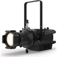
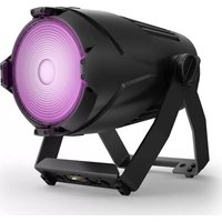
COMPACT FULL-COLOR FRESNEL SPOTLIGHT WITH RGBW-LED
SETUP AND INSTALLATION 15
INSTALL/REMOVE ACCESSORIES 15
MANUFACTURER’S DECLARATIONS 18
CONTROLLO DMX 1053 DMX DEUTSCHFRANCAIS ESPAÑOL ENGLISH ITALIANO POLSKI ENGLISH YOU‘VE MADE THE RIGHT CHOICE! We have designed this product to operate reliably over many years. Please read this User‘s Manual carefully, so that you can begin making optimum use of your Cameo Light product quickly. Learn more about Cameo Light on our website WWW.CAMEOLIGHT.COM. INTENDED USE The product is a device for event technology! The product has been specially developed for professional use in the area of event technology and is not suitable for use in a household setting! Furthermore, this product is only intended for qualified users with expertise in event technology! Use of the product contrary to the specified technical data and operating conditions is considered improper! Liability for damages or third-party damage to persons and property due to improper use is excluded! PREVENTIVE MEASURES
1. Please read these instructions carefully.
2. Keep all information and instructions in a safe place.
3. Follow the instructions.
4. Observe all safety warnings. Never remove safety warnings or other information from the equipment.
5. Use the equipment only in the intended manner and for the intended purpose.
6. Use only sufficiently stable and compatible stands and/or mounts (for fixed installations). Make certain that wall mounts are properly installed and secured. Make certain that the equipment is installed securely and cannot fall down.
7. During installation, observ e the applicable safety regulations for your country.
8. Never install and operate the equipment near radiators, heat registers, ovens or other sources of heat. Make certain that the equipment is always installed so that is cooled sufficiently and cannot overheat.
9. Never place sources of ignition, e.g., burning candles, on the equipment.
10. Ventilation slits must not be blocked.
11. This appliance is designed exclusively for indoor use, do not use this equipment in the immediate vicinity of water (does not apply to special outdoor equipment - in this case, observe the special instructions noted below). Do not expose this equipment to flammable materials, fluids or gases. 12. Make certain that dripping or splashed water cannot enter the equipment. Do not place containers filled with liquids, such as vases or drinking vessels, on the equipment.
13. Make certain that objects cannot fall into the device.
14. Use this equipment only with the accessories recommended and intended by the manufacturer.
15. Do not open or modify this equipment.
16. After connecting the equipment, check all cables in order to prevent damage or accidents, e.g., due to tripping hazards. 17. During transport, make certain that the equipment cannot fall down and possibly cause property damage and personal injuries. 18. If your equipment is no longer functioning properly, if fluids or objects have gotten inside the equipment or if it has been damaged in anot her way, switch it off immediately and unplug it from the mains outlet (if it is a powered device). This equipment may only be repaired by authorized, qualified personnel.
19. Clean the equipment using a dry cloth.
20. Comply with all applicable disposal laws in your country. During disposal of packaging, please separate plastic and paper/cardboard.
21. Plastic bags must be kept out of reach of children.
FOR EQUIPMENT THAT CONNECTS TO THE POWER MAINS: 22. CAUTION: If the power cord of the device is equipped with an earthing contact, then it must be connected to an outlet with a protective ground. Never deactivate the protective ground of a power cord. 23. If the equipment has been exposed to strong fluctuations in temperature (for example, after transport), do not switch it on immediately. Moisture and condensation could damage the equipment. Do not switch on the equipment until it has reached room temperature. 24. Before connecting the equipment to the power outlet, first verify that the mains voltage and frequency match the values specified on the equipment. If the equipment has a voltage selection switch, connect the equipment to the power outlet only if the equipment values and the mains power values match. If the included power cord or power adapter does not fit in your wall outlet, contact your electrician. 25. Do not step on the power cord. Make certain that the power cable does not become kinked, especially at the mains outlet and/or power adapter and the equipment connector. 26. When connecting the equipment, make certain that the power cord or power adapter is always freely accessible. Always disconnect the equipment from the power supply if the equipment is not in use or if you want to clean the equipment. Always unplug the power cord and power adapter from the power outlet at the plug or adapter and not by pulling on the cord. Never touch the power cord and power adapter with wet hands. 27. Whenever possible, avoid switching the equipment on and off in quick succession because otherwise this can shorten the useful life of the equipment. 28. IMPORTANT INFORMATION: Replace fuses only with fuses of the same type and rating. If a fuse blows repeatedly, please contact an authorised service centre. 29. To disconnect the equipment from the power mains completely, unplug the power cord or power adapter from the power outlet. 30. If your device is equipped with a Volex power connector, the mating Volex equipment connector must be unlocked before it can be re- moved. However, this also means that the equipment can slide and fall down if the power cable is pulled, which can lead to personal injuries and/or other damage. For this reason, always be careful when laying cables. 31. Unplug the power cord and power adapter from the power outlet if there is a risk of a lightning strike or before extended periods of disuse.4 DMX ITALIANO POLSKI ESPAÑOL FRANCAIS DEUTSCHENGLISH
32. The device must only be installed in a voltage-free condition (disconnect the mains plug from the mains).
33. Dust and other debris inside the unit may cause damage. The unit should be regularly serviced or cleaned (no guarantee) depending on ambient conditions (dust etc., nicotine, fog) by qualified personnel to prevent overheating and malfunction.
34. Please keep a distance of at least 0.5 m to any combustible materials.
35. Power cables to power multiple devices must have a cross-section of at least 1.5 mm². Within the EU, the cables must correspond to H05VV-F, or similar. Suitable cables are offered by Adam Hall. With these cables, you can connect multiple devices via the power OUT connection to the power IN connection of an additional device. Make sure that the total current consumption of all connected devices does not exceed the specified value on all connected devices (label on the device). Make sure to keep power cable connections as short as possible. CAUTION: To reduce the risk of electric shock, do not remove cover (or back). There are no user serviceable parts inside. Maintenance and repairs should be exclusively carried out by qualified service personnel. The warning triangle with lightning symbol indicates dangerous uninsulated voltage inside the unit, which may cause an electrical shock. The warning triangle with exclamation mark indicates important operating and maintenance instructions. Warning! This symbol indicates a hot surface. Certain parts of the housing can become hot during operation. After use, wait for a cool-down period of at least 10 minutes before handling or transporting the device. Warning! This device is designed for use below 2000 metres in altitude. Warning! This product is not intended for use in tropical climates. Caution! Intense LED light source! Risk of eye damage. Do not look into the light source. CAUTION! IMPORTANT INFORMATION ABOUT LIGHTING PRODUCTS!
1. Do not stare, even temporarily, directly into the light beam.
2. Do not look at the beam directly with optical instruments such as magnifiers.
3. Stroboscope effects may cause epileptic seizures in sensitive people! People with epilepsy should definitely avoid places where strobes are used. INTRODUCTION CONTROL FUNCTIONS 1 channel, 2 channel DIM, 2 channel CCT, 3 channel RGB, 4 channel RGBW, 4 channel CCT, 6 channel HSI/CCT, 7 channel RGB/CCT, 8 channel RGBW 16Bit, 10 channel HSI/CCT, 16 channel RGBW/CCT 16Bit Master / slave mode Stand-alone functions PROPERTIES 1x high power 124 W RGBW LED. 15.2° to 51.1° beam angle, manual zoom. 150 mm Fresnel lens. Configurable PWM frequency (flicker free). DMX-512 control. RDM enabled. Manual control. 4 dimmer curves. 16-bit dimming. Master/slave mode. Extremely quiet operation thanks to heat pipe cooling and fan. Operating voltage: 100–240 V AC / 50–60 Hz. Power consumption: 128 W. Mounting bracket, filter frame, and 8-way barn door included. DC input for battery operation (11–17 V). Adapter for V-mount batteries optionally available. The spotlight complies with the RDM standard (Remote Device Management). This device manager allows the user to request the status of and configure RDM end devices via an RDM-capable controller.5 DMX DEUTSCHFRANCAIS ESPAÑOL ENGLISH ITALIANO POLSKI
POWER OUT TRUE1-compatible mains output socket for power supply to additional CAMEO spotlights Ensure that the total current consumption of all connected devices does not exceed the value specified on the device in amperes (A).
FUSE Fuse holder for 5 x 20 mm micro fuses. IMPORTANT NOTE: Exclusively replace the fuse with a fuse of the same type and values (T 2AL / 250 V). If a fuse trips repeatedly, please contact an authorized service center.
DMX IN Male 5-pin XLR connector to connect a DMX control device (e.g. DMX console).
DMX OUT Female 5-pin XLR connector to transmit the DMX control signal.
OLED DISPLAY Display for the currently active operating mode and the menu items in the processing menu.
Push button rotary encoder to set and control the spotlight. DIM - When used in CCT, HSI, Direct LED, Gel, User Color or Play Loop stand-alone mode, the encoder serves as a master dimmer (rotary encoder). ENTER - 1. Pressing ENTER brings you to the menu level to select the mode. 2. This navigates you one level deeper into the menu structure. 3. Confirm the new value, such as a change to the DMX address, by pressing ENTER SELECT - Rotate the encoder to select the menu item from the menu level and change the value within the menu item (such as DMX address).
The function of the center push button rotary encoder (rotate and press) is shown on the corresponding menu item at the center of the display (middle row = rotate, lower row = press).
ZOOM Adjustment knobs for manual configuration of the beam angle are located on either side of the housing. The two knobs are positioned directly across from one another and are mechanically linked. The knobs can be turned for continuous adjustment of the spotlight beam angle, with the zoom tube on the Fresnel lens moving in and out of the housing through a gear-and-pinion system. The further the zoom tube emerges from the housing, the smaller the beam angle. A stopping mechanism is in place to prevent the tube from falling out of the housing.
- As soon as the spotlight is correctly connected to the power mains, “Welcome to Cameo”, the model designation, and then the software version are displayed in sequence on the display as part of the startup process. Once the process is complete, the spotlight is ready for use and resumes whichever mode was most recently activated.
- If one of the DMX modes or the Slave mode is active and no control signal is present at the DMX input, then the symbols on the display will begin to blink.
- If no input is received within approx. 1 minute, then the currently activated operating mode will be shown automatically on the display (main display).
DISPLAY MAIN DISPLAY DMX OPERATING MODE
The main display in DMX mode shows the currently configured DMX start address, the DMX mode and other information (see illustration).
= DMX signal present
= no DMX signal currently activated mode DMX start address and DMX mode Fan mode Press encoder = Open main menu Press encoder = select mode
BATTERY Male 4-pin XLR socket connection to an external rechargeable battery (battery not included). A mounting plate with V-mount adapter and connection cable is optionally available (article number CLF1VMOUNTAP).7 DMX DEUTSCHFRANCAIS ESPAÑOL ENGLISH ITALIANO POLSKI SETTING THE DMX START ADDRESS (DMX Address) Starting from the main display, press on the right push button rotary encoder to move to the main menu. Rotate the left encoder (SELECT) to select the "DMX Address" menu item (as indicated by selector arrow on left) and confirm by pressing the encoder (ENTER). You can now config- ure the DMX start address as desired by rotating the left encoder (highest value reflects the active DMX operating mode). At the same time, the following address, i.e. the DMX start address derived from the selected start address plus the channel number for the selected DMX mode, is also shown. Confirm the entry by pressing on the left encoder (ENTER), which then returns you automatically to the main display and activates the DMX mode. The menu item for selecting the desired DMX mode is reached directly from the "DMX Address" menu item by pressing on the middle push button rotary encoder (DMX mode), while the previously configured DMX start address is then saved automatically. Press encoder = Open main menu Rotate encoder = change value Press encoder = confirm change to value (enter) Press encoder = select the DMX mode SETTING THE DMX MODE (DMX Mode) Starting from the main display, press on the right push button rotary encoder to move to the main menu. Rotate the left encoder (SELECT) to select the "DMX Mode" menu item (as indicated by selector arrow on left) and confirm by pressing the left encoder (ENTER). You can now select the desired DMX mode by rotating the left encoder. Confirm the choice by pressing on the left encoder (ENTER), which then returns you automatically to the main display and activates the DMX mode. You can find tables on channel assignment in the different DMX modes in these instructions under DMX CONTROL. 1CH DIM 2CH DIM 16Bit 2CH CCT 3CH RGB cal. 4CH Direct 4CH CCT 16Bit 6CH HSI-CCT 7CH RGB-CCT 8CH Direct 16Bit 10CH HSI-CCT 16CH Direct-CCT
BATTERY Male 4-pin XLR socket connection to an external rechargeable battery (battery not included). A mounting plate with V-mount adapter and connection cable is optionally available (article number CLF1VMOUNTAP).8 DMX ITALIANO POLSKI ESPAÑOL FRANCAIS DEUTSCHENGLISH STAND-ALONE MODE HSI (Hue - Saturation - Intensity) Starting from the main display, press on the left push button rotary encoder to move to the mode select menu. Rotate the left encoder (SELECT) to select "HSI" mode (as indicated by selector arrow on left) and confirm by pressing the left encoder (ENTER). Dim level, hue and color saturation (SAT) can now be configured using the three push button rotary encoders (see illustration). currently activated mode Fan mode Rotate encoder = set color saturation (SAT) Press encoder = Open main menu Rotate encoder = set DIM Press encoder = select mode Rotate encoder = set Hue STAND-ALONE MODE CCT (Correlated Color Temperature) Starting from the main display, press on the left push button rotary encoder to move to the mode selection menu. Rotate the left encoder (SELECT) to select "CCT" mode (as indicated by selector arrow on left) and confirm by pressing the left encoder (ENTER). Dim level, correlated color temperature (CCT) and tint can now be configured using the three push button rotary encoders (see illustration). currently activated mode Fan mode Rotate encoder = set Tint Press encoder = Open main menu Rotate encoder = set DIM Press encoder = select mode Rotate encoder = set correlated color temperature (CCT)9 DMX DEUTSCHFRANCAIS ESPAÑOL ENGLISH ITALIANO POLSKI STAND-ALONE MODE DIRECT LED (RGBW color mix) Starting from the main display, press on the left push button rotary encoder to move to the mode selection menu. Rotate the left encoder (SELECT) to select "Direct LED" mode (as indicated by selector arrow on left) and confirm by pressing the left encoder (ENTER). The total brightness and intensity levels for R, G, B and W can now be configured using the three push button rotary encoders (see illustration). currently activated mode Fan mode Rotate encoder Set G and W dim levels Press encoder = Open main menu Rotate encoder = set overall brightness level (DIM) Press encoder = select mode Rotate encoder Set R and B dim levels Press encoder = switch between R+G and B+W (Color) STAND-ALONE MODE GEL (Color Filter Presets) Starting from the main display, press on the left push button rotary encoder to move to the mode selection menu. Rotate the left encoder (SELECT) to select "GEL" mode (as indicated by selector arrow on left) and confirm by pressing the left encoder (ENTER). The brightness level (DIM) and color filter preset (Gel) can now be set using the left and center push button rotary encoder (see illustration). The color filter presets with Lee filter designations and corresponding Rosco filter numbers can be found in the DMX tables under DMX CONTROL (channel "Color Presets", such as in 10-channel mode, without "User Color 1-8"). currently activated mode Fan mode Press encoder = Open main menu Rotate encoder = set overall brightness level (DIM) Press encoder = select mode Rotate encoder = select filter preset10 DMX ITALIANO POLSKI ESPAÑOL FRANCAIS DEUTSCHENGLISH STAND-ALONE MODE EDIT USER color (Edit User Color) Starting from the main display, press on the right push button rotary encoder to move to the main menu. Rotate the left encoder (SELECT) to select "Edit User Color" menu item (as indicated by selector arrow on left) and confirm by pressing the left encoder (ENTER). You can now select one of the 8 color presets by rotating the left encoder and then confirm the selection by pressing on the left encoder (ENTER). Now enter a custom name of up to 12 digits to be assigned to the preset (Edit User Color Name) by rotating the left encoder to a letter, underscore or number for the first position of the preset name, confirming the selection by pressing on the left encoder. The second position etc is chosen in the same way. Once the preset name is complete, press the center encoder (Save&Next) to move to the next step of editing. If you press on "Save&Next" without selecting a letter, underscore or number for the first position, then the previous preset name is retained and you move immediately to the next step of editing. Now you can decide in which way you wish to create the color for the preset, i.e. one of the 4 methods "CCT", "HSI", “DIRECT" and "GEL", as selected by rotating the left encoder (SELECT) and confirmed by pressing the left encoder (ENTER). You should now set the desired color as described in the instructions for the respective stand-alone mode and then confirm by pressing on the left encoder (ENTER/Save). STAND-ALONE MODE USER COLOR (Individual color presets 1 - 8) Starting from the main display, press on the left push button rotary encoder to move to the mode selection menu. Rotate the left encoder (SELECT) to select "User Color" mode (as indicated by selector arrow on left) and confirm by pressing the left encoder (ENTER). Now select one of the 8 preset but customizable user colors by rotating the left encoder. Confirm the selection by pressing the left encoder (ENTER). The brightness level (DIM) of the user color can now be set using the left encoder (see illustration). The individual preset settings and the name of the user color can be modified using the "Edit User Color" menu item. currently activated mode Fan mode Press encoder = Open main menu Rotate encoder = set DIM Press encoder = select mode Rotate encoder = select filter preset11 DMX DEUTSCHFRANCAIS ESPAÑOL ENGLISH ITALIANO POLSKI STAND-ALONE MODE PLAY LOOP (8-step color sequences 1 - 8) Starting from the main display, press on the left push button rotary encoder to move to the mode selection menu. Rotate the left encoder (SELECT) to select "Play Loop" mode (as indicated by selector arrow on left) and confirm by pressing the left encoder (ENTER). Now select one of the 8 preset but customizable color sequences (loops) by rotating the left encoder. Confirm the selection by pressing the left encoder (ENTER). The brightness (DIM) of the color loop can now be set using the left encoder, while the step duration (0.1 second to 21 minutes, with 2 random modes) and fade times (0 seconds to 18 minutes, with 2 random modes) are configured using the center and right encoders respectively (see illustration). The individual settings and the name of the color loops can be modified using the "Edit Loop" item in the main menu. currently activated mode Fan mode Rotate encoder = set fade time (t-Fade) Press encoder = Open main menu Rotate encoder = set brightness (DIM) Press encoder = select mode Rotate encoder = set step duration (t-Fade) Press encoder = return to color loop selection (Back) STAND-ALONE MODE EDIT PLAY LOOP (Edit Loop) Starting from the main display, press on the right push button rotary encoder to move to the main menu. Rotate the left encoder (SELECT) to select "Edit Loop" menu item (as indicated by selector arrow on left) and confirm by pressing the left encoder (ENTER). You can now select one of the 8 color sequences (loops) by rotating the left encoder and then confirm the selection by pressing on the left encoder (ENTER). Now enter a custom name of up to 12 digits to be assigned to the color loop (Edit Loop Name) by rotating the left encoder to a letter, underscore or number for the first position of the preset name, confirming the selection by pressing on the left encoder. The second position etc. is chosen in the same way. Once the preset name is complete, press the center encoder (Save&Next) to move to the next step of editing. If you press on "Save&Next" without selecting a letter, underscore or number for the first position, then the previous preset name is retained and you move immediately to the next step of editing. Select Step 1 from the 8-step loop (Step1-Step 8) by rotating the left encoder to determine the color for the step (Step 1, note the selection arrow). Now select one of the colors in the stand-alone mode "User Color" by rotating the center encoder and confirm the selection for Step 1 by pressing on the middle encoder. The selected color for the respective step is displayed visually in a box on a light background below the color number 1 to 8. The same method is used to set the colors for steps 2 through 8. Close the process and save the loop by pressing on the left encoder (ENTER).12 DMX ITALIANO POLSKI ESPAÑOL FRANCAIS DEUTSCHENGLISH currently activated mode Fan mode Press encoder = Open main menu Press encoder = select mode DMX MODE Starting from the main display, press on the left push button rotary encoder to move to the mode selection menu. Rotate the left encoder to select the "DMX" menu item (as indicated by selector arrow on left) and confirm by pressing the encoder (ENTER). DMX mode is now activated and the main display is automatically shown again. Select one of the ten available DMX modes in the menu item "DMX Mode" in the main menu (see SET DMX MODE). SLAVE MODE Starting from the main display, press on the left push button rotary encoder to move to the mode selection menu. Rotate the left encoder to select the “Slave” menu item (as indicated by selector arrow on left) and confirm by pressing the encoder (ENTER). Slave mode is now activated and the main display is automatically shown again. Connect the slave and master unit (same model, same software version) using a DMX cable, and activate one of the stand-alone modes on the master unit. The slave unit will now follow the master unit.13 DMX DEUTSCHFRANCAIS ESPAÑOL ENGLISH ITALIANO POLSKI DEVICE SETTINGS (Settings) Starting from the main display, press on the right push button rotary encoder to move to the main menu. Rotate the left encoder (SELECT) to select "Settings" menu item (as indicated by selector arrow on left) and confirm by pressing the left encoder (ENTER). This will take you to the submenu for setting the submenu options (see table, select via SELECT, confirm via ENTER, change value or status via SELECT, confirm via ENTER). Settings Display Flip = Display rotation Standing Position No rotation of the display Hanging Position Display is rotated by 180° (e.g. for overhead installation) Display Time off = Display lighting Display always on Permanently on Display off after 20s Deactivates after approximately 20 seconds of inactivity DMX Fail = Operational status with DMX signal fault Hold Last command is retained Blackout Activates blackout User Color 8 Activates User Colour 8 Dimmer Curve = Dimmer curve Linear Light intensity increases linearly with DMX value Exponential Light intensity can be finely adjusted at lower DMX values and broadly adjusted at higher DMX values Logarithmic Light intensity can be broadly adjusted at lower DMX values and finely adjusted at higher DMX values S-Curve Light intensity can be finely adjusted at lower and higher DMX values and broadly adjusted at medium DMX values Dimmer Response = Dimmer response LED Light responds abruptly to changes in DMX value Halogen Light behaves like a halogen spotlight with slight brightness changes Red Shift = Accurately mimics the colour drift of dimming a halogen spotlight. When dimming the spotlight, the colour temperature changes automatically to increasingly warm white and amber (and vice versa). No Colour drift is disabled Dim To Warm Colour drift is enabled PWM-Frequency = LED PWM frequency 600 Hz / 1200 Hz / 2000 Hz / 4000 Hz / 6000 Hz / 25k Hz Configuration of LED PWM frequency Color Calibration = Colour calibration RAW - Off R, G, B and W with maximum value 255 RAW - Adjust (Individuelle, betriebs- artübergreifende Anpassung von R, G, B, und W mit Werten von jeweils 000 bis 255) Press middle encoder = switch between R+G and B+W (colour) Rotate middle encoder = set value of R or B Press right encoder = one level up in menu structure (ESC) Rotate right encoder = set value of G or W Press left encoder = confirm and save settings Calibrated Factory calibration of R, G, B and W (across all modes). Select this setting for the correct display of colour shades and presets in the standalone modes CCT and Gel, as well as when controlling CCT and the presets Gel via DMX. Smart Calibration Merge Factory (calibrated) and RAW calibration Autolock = Automatic locking of the controls
Automatic locking of the controls after approxima- tely 30 seconds of inactivity. Display shown upon attempted use: “Locked!” Unlock: Simultaneously press the centre and right encoders for approx. 3 seconds Off Automatic locking of the controls is disabled Fan = Fan setting Auto Automatic fan control Off Deactivated fan with greatly reduced brightness Constant Low Constantly low fan speed with reduced brightness, if necessary14 DMX ITALIANO POLSKI ESPAÑOL FRANCAIS DEUTSCHENGLISH SYSTEM INFORMATION (System Info) Starting from the main display, press on the right push button rotary encoder to move to the main menu. Rotate the left encoder (SELECT) to select "System Info" menu item (as indicated by selector arrow on left) and confirm by pressing the left encoder (ENTER). Rotate the left encoder to display the desired information (see chart). System Info Main CPU Device firmware LED Temp. Displays the LED temperature in Celsius or Fahrenheit Op. Hours Cumulative operating time in hours and minutes Display Activates/deactivates display DMX Fail Operating mode if DMX signal is lost Dim Curve Dimmer Curve Dim Response Dimmer behavior Red Shift Activates/deactivates color drift PWM LED PWM frequency Calibr. Factory default calibration / no adjustment / user defined adjustment Color-Cal. R Adjusts red (independent of mode) Color-Cal. G Adjusts green (independent of mode) Color-Cal. B Adjusts blue (independent of mode) Color-Cal. W Adjusts white (independent of mode) Autolock Activates/deactivates automatic locking of the control element Fan Fan settings
MANUAL LOCK FUNCTION
While the option is available to have the spotlight lock itself automatically against unintentional or unauthorized use (see "Settings" - "Au- tolock"), it is also possible to lock the controls manually. Press the center and right push button rotary encoders simultaneously for approx. 3 seconds. Any subsequent attempt to change the controls will display "Locked!" on the display and no further changes to the spotlight settings can be made via the encoders. After approx. 1 minute the name of the currently set mode then returns. To unlock the controls, press the center and right push button rotary encoders simultaneously for approx. 3 seconds. The display then returns to whichever information it had been showing before the lock was applied. linear DMX value Light intensity exponential DMX value Light intensity logarithmic DMX value Light intensity S-curve DMX value Light intensity DIMMER CURVES Fan = Fan setting Constant Medium Constant average fan speed with reduced bright- ness, if necessary Constant High Constant high fan speed Factory Reset = Restore factory settings (without resetting user colours and loops) Reset Now? Reset to factory settings: confirm with ENTER, cancel with ESC UC/Loops Reset = Reset the user colours and loops to factory settings Reset User Colors/ Loops Reset to factory settings: confirm with ENTER, cancel with ESC15 DMX DEUTSCHFRANCAIS ESPAÑOL ENGLISH ITALIANO POLSKI
SETUP AND INSTALLATION
Thanks to its four plastic feet, the spotlight can be placed in a suitable location on a flat surface. Install on a crossbeam using the prein- stalled mounting bracket (A) and a suitable crossbeam clamp (available as an accessory). Make sure that the spotlight is firmly attached and secure it using a suitable safety cable on the designated location on the top of the spotlight (B). Use the lever screw (C) located on one side to adjust the vertical radiation direction. A distance of at least 0.1 m must be kept between objects or walls located beside, above and behind the spotlight; a distance of at least
0.5 m must be kept in front of the spotlight in the cone of light.
Warning: Overhead installation requires extensive experience, including the calculation of the load limit values of the installa- tion material and regular safety inspection of all installation materials and spotlights. If you do not have these qualifications, do not attempt to carry out the installation yourself; contact a professional company. There is a risk that incorrectly mounted or secured devices may come loose and fall down. This may lead to serious injury and even fatalities.
INSTALL/REMOVE ACCESSORIES
To install or remove the barn doors and the filter frame, please push the spring-loaded locking pin (D) of the bracket so that it folds upwards. Do not forget afterwards to return the retaining bracket back to the original position so that the lock pins click back into their locked position.
Warning: For safety reasons, the filter frame must always be in the respective bracket on the spotlight, even if no filter is inserted!
Warning: Always secure the filter frame, and the barn door if used, to the spotlight using the enclosed safety cable!16
DMX ITALIANO POLSKI ESPAÑOL FRANCAIS DEUTSCHENGLISH DMX TECHNOLOGY DMX-512 DMX (Digital Multiplex) is the designation for a universal transmission protocol for communications between corresponding devices and controllers. A DMX controller sends DMX data to the connected DMX device(s). The DMX data is always transmitted as a serial data stream that is forwarded from one connected device to the next via the "DMX IN" and "DMX OUT" connectors (XLR plug-type connectors) that are found on every DMX-capable device, provided the maximum number of devices does not exceed 32 units. The last device in the chain needs to be equipped with a terminator (terminating resistor). DMX CONNECTION DMX is the common "language" via which a very wide range of types and models of equipment from various manufacturers can be connected with one another and controlled via a central controller, provided that all of the devices and the controller are DMX compatible. For optimum data transmission, it is necessary to keep the connecting cables between the individual devices as short as possible. The order in which the devices are integrated in the DMX network has no influence on the addresses. Thus the device with the DMX address 1 can be located at any position in the (serial) DMX chain: at the beginning, at the end or somewhere in the middle. If the DMX address 1 is assigned to a device, the controller "knows" that it should send all data allocated to address 1 to this device regardless of its position in the DMX network.
CARE AND MAINTENANCE – CLEANING LENSES
The front lens (E) and its rubber frame can be cleaned by flipping the retaining bracket upwards as previously described and then drawing the front lens and its rubber frame as well as the filter frame upwards out of the retention arms. Clean the front lens with a moist, lint-free cloth, making sure not to scratch the surface of the lens. Do not put the front lens and filter frame back into the support arms until all equipment and accessories are completely dry. Then return the retaining bracket back to its downward position until the lock pins click into place.
OPTIONAL ACCESSORIES A mounting plate with V-mount adapter and connection cable for an external standard 14.4 or 14.8 volt V-mount battery is optionally available. Article number: CLF1VMOUNTAP17 DMX DEUTSCHFRANCAIS ESPAÑOL ENGLISH ITALIANO POLSKI TECHNICAL SPECIFICATIONS
SERIAL CONNECTION OF MULTIPLE LIGHTS
1. Connect the male XLR connector (3-pin or 5-pin) of the DMX cable to the DMX output (female XLR socket) of the first DMX device (e.g. DMX-Controller). 2. Connect the female 3-pin XLR connector of the DMX cable connected to the first projector to the DMX input (male 3-pin socket) of the next DMX device. In the same way, connect the DMX output of this device to the DMX input of the next device and repeat until all devices have been connected. Please note that as a rule, DMX devices are connected in series and connections cannot be shared without active splitters. The maximum number of DMX devices in a DMX chain should not exceed 32 units. The Adam Hall 3 STAR, 4 STAR, and 5 STAR product ranges include an extensive selection of suitable cables. DMX CABLES When fabricating your own cables, always observe the illustrations on this page. Never connect the shielding of the cable to the ground contact of the plug, and always make certain that the shielding does not come into contact with the housing of the XLR plug. If the shielding is connected to the ground, this can lead to short-circuiting and system malfunctions. Pin Assignment DMX cable with 3-pin XLR connectors: DMX cable with 5-pin XLR connectors (pin 4 and 5 are not used): Shield
Shield DMX TERMINATORS (TERMINATING RESISTORS) To prevent system errors, the last device in a DMX chain needs to be equipped with a terminating resistor (120 ohm, 1/4 Watt). 3-pin XLR connector with a terminating resistor: K3DMXT3 5-pin XLR connector with a terminating resistor: K3DMXT5 Pin Assignment 3-pin XLR connector: 5-pin XLR connector:
DMX ADAPTER The combination of DMX devices with 3-pin connectors and DMX devices with 5-pin connectors in a DMX chain is possible with suitable adapters. Pin Assignment DMX Adapter 5-pin XLR male to 3-pin XLR female: K3DGF0020 Pins 4 and 5 are not used. Pin Assignment DMX Adapter 3-pin XLR male to 5-pin XLR female: K3DHM0020 Pins 4 and 5 are not used. Article number: CLF1FC Product type: LED Spotlight Type: Fresnel Spotlight with Zoom Function Color spectrum: RGBW (CCT 1600 K – 6500 K) CRI: 90 Number of LEDs: 1 LED array (Rx10, Gx10, Bx6, Wx20) LED type: 124 W LED PWM frequency: 600 Hz, 1200 Hz, 2000 Hz, 4000 Hz, 6000 Hz, 25 kHz (adjustable) Beam angle: 15.2° to 51.1° (field 25.5° to 75°) DMX input: 5-pin XLR, male (Seetronic) DMX output: 5-pin XLR, female (Seetronic18 DMX ITALIANO POLSKI ESPAÑOL FRANCAIS DEUTSCHENGLISH
MANUFACTURER´S DECLARATIONS
CORRECT DISPOSAL OF THIS PRODUCT
Color Temperature (affects RGB and HSI)
Color Temperature (affects RGB and HSI)
006 - 010 Strobe closed
Strobe Break effect, 5s…..1s (short burst with break)
Color Tempe- rature (affects RGBW and HSI)
Color Presets (overrides RGBW, HSI, Color Tempe- rature) Lee Filter No. Color Presets Roscolux Filter No.
Color Presets (overrides RGBW, HSI, Color Tempe- rature)
106 - 214 11s - 119s (1s Steps)
215 - 244 2m - 4m50s (10s Steps)
Default set (except DMX-Address, DMX-Mode and User Color/Loops) (hold 3s)