SPI9961SET5 - Satellite receiver Schwaiger - Free user manual and instructions
Find the device manual for free SPI9961SET5 Schwaiger in PDF.

| Product type | Satellite multiswitch |
| Brand | Schwaiger |
| Model | SPI9961SET5 |
| Number of satellite inputs | 4 |
| Number of terrestrial/TV inputs | 1 |
| Number of outputs | 6, 8, 12 or 16 depending on version |
| Satellite frequency range | 950 - 2150 MHz |
| Terrestrial/TV frequency range | 47 - 862 MHz |
| Satellite attenuation | typ. -10 to -3 dB |
| Terrestrial/TV attenuation | typ. -5 dB |
| Input decoupling | 25 dB |
| Internal consumption | max. 30 mA |
| LNB power supply | max. 500 mA |
| Mains power supply | 230 V / 15 W max |
| Dimensions (L x W x H) | 140/140/180/215 x 142 x 40 mm |
| Weight | 0.6 kg (estimated) |
| Connectors | F |
| Installation instructions | Mount in dry and ventilated rooms, on a fireproof support |
| Safety | Grounding via earth terminal |
| Maintenance and cleaning | Clean with a dry cloth, do not use chemicals |
| Main functions | Distribution of analog/digital satellite and terrestrial signals |
Frequently Asked Questions - SPI9961SET5 Schwaiger
User questions about SPI9961SET5 Schwaiger
0 question about this device. Answer the ones you know or ask your own.
Ask a new question about this device
Download the instructions for your Satellite receiver in PDF format for free! Find your manual SPI9961SET5 - Schwaiger and take your electronic device back in hand. On this page are published all the documents necessary for the use of your device. SPI9961SET5 by Schwaiger.
USER MANUAL SPI9961SET5 Schwaiger
3.0. Installationshinweise
flowchart
graph TD
    TV_TV["TV TV"] --> Receiver["Receiver"]
    Receiver --> SEW_512["SEW 512"]
    SeW_512 --> Quattro_LNB["Quattro LNB"]
    SeW_512 --> BN_2338["BN 2338"]
    WN_HF["UHF"] --> UHF
    UKW_UKW["UKW"] --> UKW
    VHF["VHF"] --> VHF
    WN_W["UNW"] --> WN_W
    WN_W --> DSE_650["DSE 650"]
    WN_W --> DSE_652["DSE 652"]
    DSE_650 --> Twin_Receiver["Twin-Receiver"]
    DSE_652 --> Twin_Receiver
    WN_W --> WN_W
    WN_W --> WN_W
    WN_W --> WN_W
    WN_W --> WN_W
    WN_W --> WN_W
    WN_W --> WN_W
    WN_W --> WN_W
    WN_W --> WN_W
    WN_W --> WN_W
    WN_W --> WN_W
    WN_W --> WN_W
    WN_W --> WN_W
    WN_W --> WN_W
    WN_W --> WN_W
    WN_W --> WN_W

    style WN_W fill:#f9f,stroke:#333
    style WN_W fill:#ccf,stroke:#333
    style WN_W fill:#cfc,stroke:#333
    style WN_W fill:#fcc,stroke:#333
    style WN_W fill:#cff,stroke:#333
    style WN_W fill:#ffc,stroke:#333
    style WN_W fill:#fcc,stroke:#333
    style WN_W fill:#ffc,stroke:#333
    style WN_W fill:#fcc,stroke:#333
    style WN_W fill:#ffc,stroke:#333
    style WN_W fill:#fcc,stroke:#333
    style WN_W fill:#ffc,stroke:#333
    style WN_W fill:#fcc,stroke:#333
    style WN_W fill:#ffc, stroke:#333
    style WN_W fill:#fcc,stroke:#333
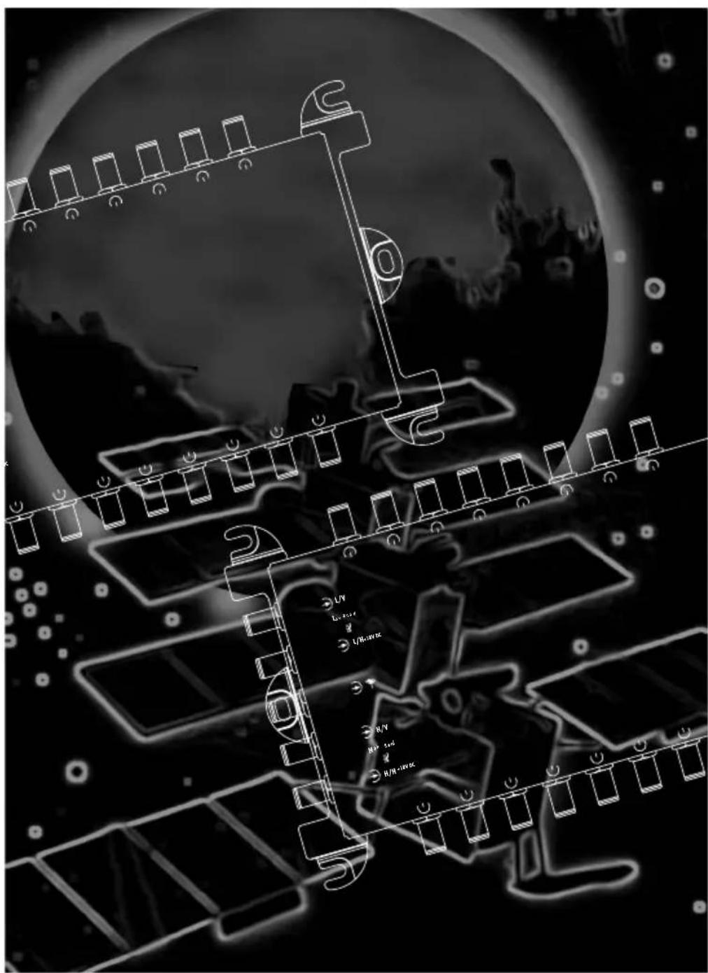
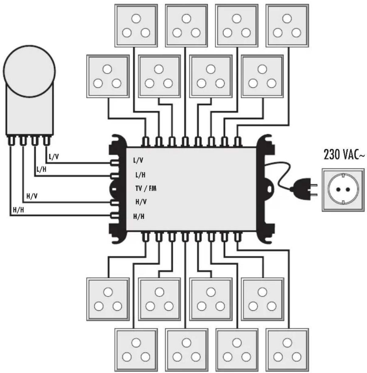
Installation information for the Multiswitch 5 in 6/8/12/16 out
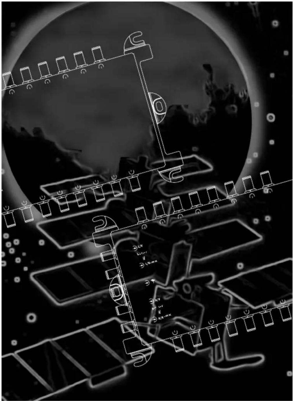
Multiswitch - Mounting Instructions
The multiswitch allows the distribution of analogue and digital signals from one satellite position or four reception levels.
It provides the option to feed in terrestrial channels, e.g. in order to integrate FM-radio stations or regional analog oder digital (DVB-T) TV stations into the TV network.
HINT: Please read the operating instructions carefully and be aware to observe all security advices before starting your multi-switch system.
1.0. Explanation of the Terms Used in the Mounting Instructions
Analog channels:
= „low“ frequency band (frequency range : 10.70 - 11.70 GHz)
Digital channels:
= „high“ frequency band (frequency range : 11.70 - 12.75 GHz)
Vertical plane of polarization (V) : DC voltage typ. +14 V
Horizontal plane of polarization (H) : DC voltage typ. +18 V
Characteristic frequency 22 kHz :
The 0/22 kHz characteristic frequency is used
for switch-over from the LNB1/low band to the LNB1/high band.
2.0. Multiswitch Control
The multiswitch is controlled via the familiar analogue switching criteria.
-Activating the multiswitch by means of the usual analog switching media 14/18 V and 22 kHz may provide access to max. two frequency bands. (LNB1/low - LNB1/high)
3.0. Installation Instructions
The currently valid safety requirements must be observed! (See enclosed sheet of instructions „Important Safety Hints“)
3.1. LNBs
A universal quattro LNB (e.g. the Schwaiger SPS 6918) can be used as a feed system for receiving analogue and digital channels from a single SAT position.
HINT :
When using other LNB types, be aware of their current demand!
(see chapter 3.2. of these instructions)
3.2. LNB Power Supply
The power supply of the LNBs is performed by means of the power supply unit at the multiswitch.
IMPORTANT: Use only the original Schwaiger mains adaptor!
A total maximum of 500mA are available to feed the LNB.
(18V to the LNB inputs L/H + H/H)
3.4. System Cabling
- T3.4 The system must have a star-topology distribution structure from the multiswitch to the antenna sockets (e.g. Schwaiger DSE 650 or DSE 652), i.e. only one receiver may be connected to each output on the multiswitch. For twin receivers you require two supply lines.
- Use 75 Ohm coaxial cables for system cabling (e.g. Schwaiger KOX 110).
- Subsequent to mounting the F connectors, check the coaxial cables for short circuits.
3.5. It is recommended that you terminate all the unused multiswitch inputs and outputs with 75 Ohm terminators (e.g. Schwaiger ÜST 8380 201).
3.6. Mounting of the Multiswitch
Multiswitches must only be installed in dry rooms with sufficient ventilation.
Moreover, multiswitches must be mounted to a hardly flammable ground.
IMPORTANT:
During constant operation at 25^ C room temperature, some parts of the multiswitch carry a temperature of up to 55^ C, depending on the current input of the LNB type used.
3.7. Protective Arrangement
The multi switch needs to be grounded by way of its grounding terminal!
4.0. Technical Data
| Product 5 in 6/8/12/16 out | |
| Number of outputs 6 / 8 | 12 / 16 | |
| Connections F | |
| SAT | |
| Number of inputs 4 | |
| Frequency range 950 - 2150 MHz | |
| Transmission typ. -10...-3dB | typ. -13...-6dB | |
| H/V isolation 25 dB | |
| EN 50083-3 (35dB) 100 dBμV | |
| RDF/TV | |
| Number of inputs 1 | |
| Frequency range 47-862 MHz | |
| Transmission typ. -5 | typ. -10 | |
| EN 50083 - 3 (60dB) typ. 85 dBμV / 82 dBμV | |
| Induced current input from receiver max.30 mA | |
| Power supply for LNB max. 500 mA | |
| Power supply | 230 V / 15 Watt max |
| Dimensions | 140/140/180/215 x 142 x 40 mm |
For further questions, please do not hesitate to contact us. Our hotline for technical information : +49 (0)9101 / 702-299
Subject to change without prior notice. / Errors excepted.
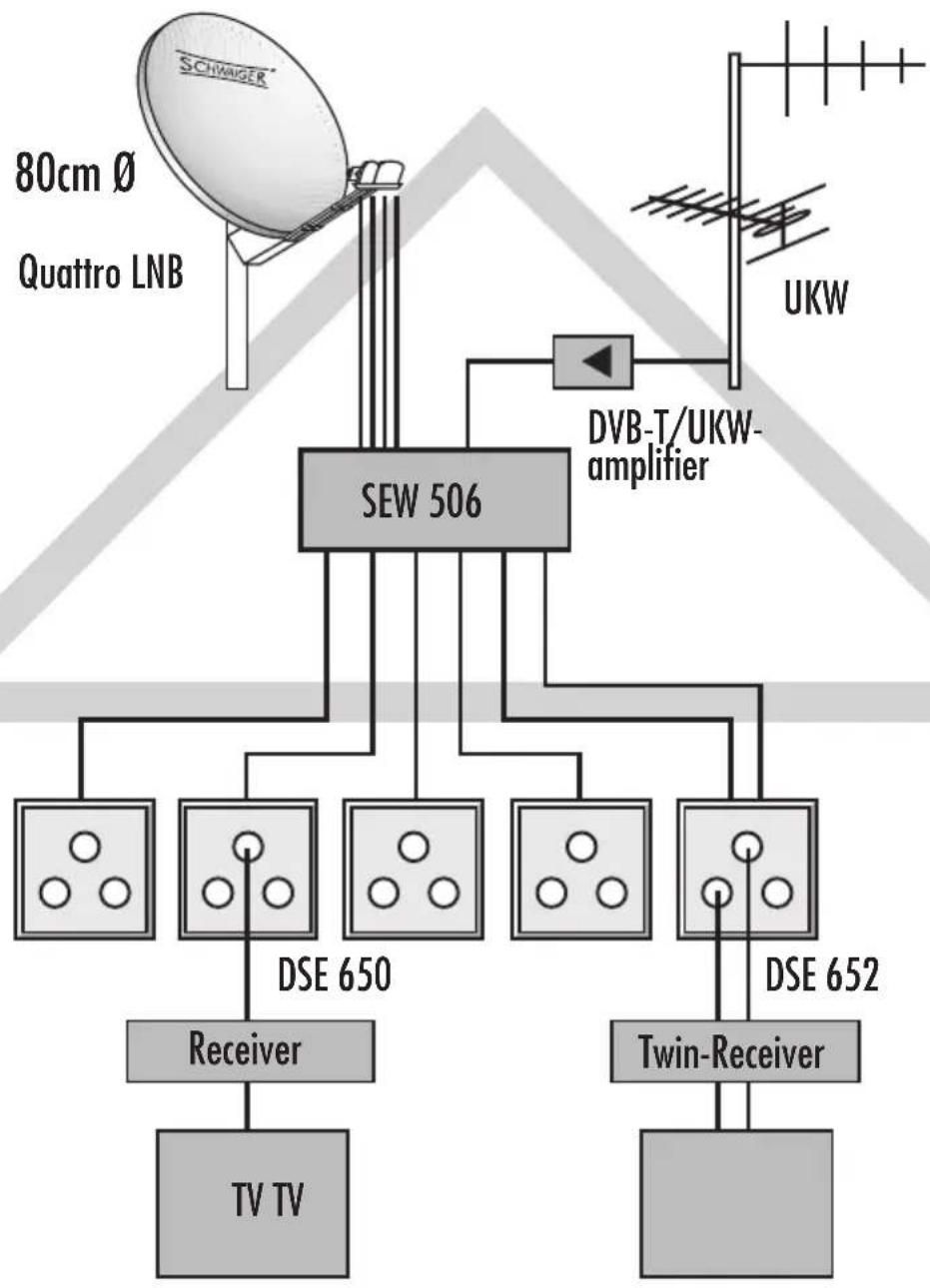
flowchart
graph TD
    A["Schwinger"] --> B["80cm Ø Quattro LNB"]
    B --> C["SEW 506"]
    C --> D["DVB-T/UKW-amplifier"]
    D --> E["DSE 650"]
    D --> F["DSE 652"]
    E --> G["Receiver"]
    F --> H["Twin-Receiver"]
    G --> I["TV TV"]
    H --> J["UKW"]
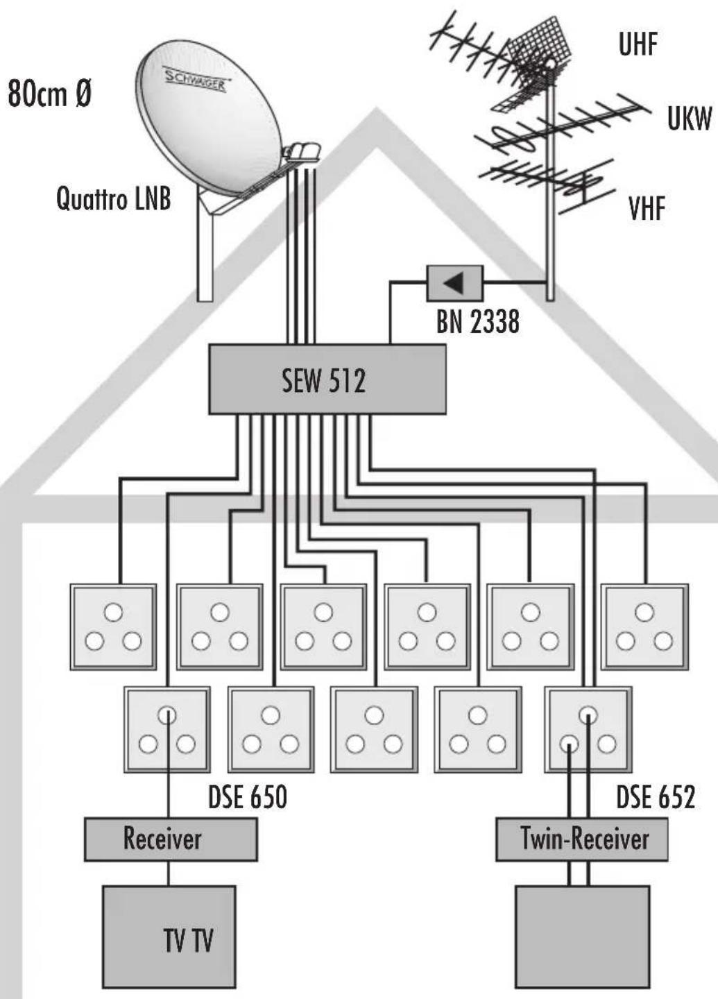
flowchart
graph TD
    TV_TV["TV TV"] --> Receiver["Receiver"]
    Receiver --> SEW_512["SEW 512"]
    SeW_512 --> Quattro_LNB["Quattro LNB"]
    SeW_512 --> BN_2338["BN 2338"]
    WN_AU["WH"] --> UHF["UHF"]
    WN_AU --> UKW_UKW["UKW"]
    WN_AU --> VHF["VHF"]
    WN_AU --> DSE_650["DSE 650"]
    WN_AU --> DSE_652["DSE 652"]
    DSE_650 --> Twin_Receiver["Twin-Receiver"]
    DSE_652 --> Twin_Receiver
    WN_AU --> DSE_650
    WN_AU --> DSE_652
    WN_AU --> UHF
    WN_AU --> UKW_UKW
Instructions de montage du multiswitch 5 in 6/8/12/16