SDJ4000 - DJ Equipment GEMINI - Free user manual and instructions
Find the device manual for free SDJ4000 GEMINI in PDF.
| Product Type | Professional standalone DJ media player |
| Brand | Gemini |
| Model | SDJ4000 |
| Dimensions (approx.) | 350 × 450 × 120 mm |
| Weight (approx.) | 6.5 kg |
| Power Supply | AC 100-240 V, 50/60 Hz (power cable included) |
| Power Consumption | Approx 50 W |
| Number of Decks | Dual Deck |
| Display | HD color screen with playback information display |
| Audio Sources | USB ports 1 and 2, Line/Phono inputs (CH1 to CH4), microphone inputs (MIC 1 and MIC 2) |
| Supported Formats | MP3, WAV, FLAC, AAC (via USB formatted as FAT32) |
| Included Software | V-CASE (music management and analysis) |
| Main Functions | Playback, scratch, loops, hot cues, effects, sync, USB recording |
| Effects | Filter, Chop, Noise, Flanger, and parametric MFX effects |
| Performance Pads | 8 pads per deck with Hot Cue, Loop, Sampler, Slicer, Roll, Keyplay modes |
| Audio Outputs | Master XLR/RCA, Booth RCA, headphone (6.35 mm and 3.5 mm jacks) |
| Connectivity | USB ports, MIDI, Ethernet (LINK) |
| Care and Cleaning | Wipe with a soft, dry cloth. Avoid liquids and moisture. |
| Operating Temperature | +5 °C to +35 °C |
| Safety | Do not open the device. Disconnect before maintenance. Use on a stable surface. |
| Spare Parts and Repairability | Repair by Gemini authorized center. Contact support for parts. |
| Warranty | 1-year limited warranty |
Frequently Asked Questions - SDJ4000 GEMINI
User questions about SDJ4000 GEMINI
0 question about this device. Answer the ones you know or ask your own.
Ask a new question about this device
Download the instructions for your DJ Equipment in PDF format for free! Find your manual SDJ4000 - GEMINI and take your electronic device back in hand. On this page are published all the documents necessary for the use of your device. SDJ4000 by GEMINI.
USER MANUAL SDJ4000 GEMINI
natural_image
Black gemini audio synthesizer with dual dials and control knobs (no visible text or symbols on main body)WWW.GEMINISOUND.COM
| ENGLISH - PAGE 2 | SPANISH - PAGE 8 |
| FRENCH - PAGE 14 | GERMAN - PAGE 20 |
gemini
INTRODUCTION
Thank you for purchasing our SDJ-4000 Standalone Professional Media Player. We are confident that the Gemini platform of products will not only make your life easier through the use of the latest technological advancements in cross-platform connectivity and sound reproduction but will raise the bar for DJ and pro audio products. With the proper care & maintenance, your unit will likely provide years of reliable, uninterrupted service. All Gemini products are backed by a 1-year limited warranty*.
OPERATING CONDITIONS
For optimum performance, the temperature of the operating environment should be between +5°C to +35°C (+41°F - +95°F). Failure to maintain proper operating temperature may result in difficulty reading the display, thermal overload, or systemwide instability. Avoid exposing the unit to direct sunlight. When placing the unit in an installation, make sure that it is placed on a stable surface, as far away from vibrations as possible. Even though the unit is impervious to vibration, the storage devices that are designed to be used in conjunction with it may not be. Also, be sure not to place or use the SDJ-4000 on heat generating sources, such as amplifiers or near spotlights.
V-CASE MUSIC ANALYSIS & MANAGEMENT SOFTWARE
IMPORTANT - Visit geminisound.com/v-case to download.
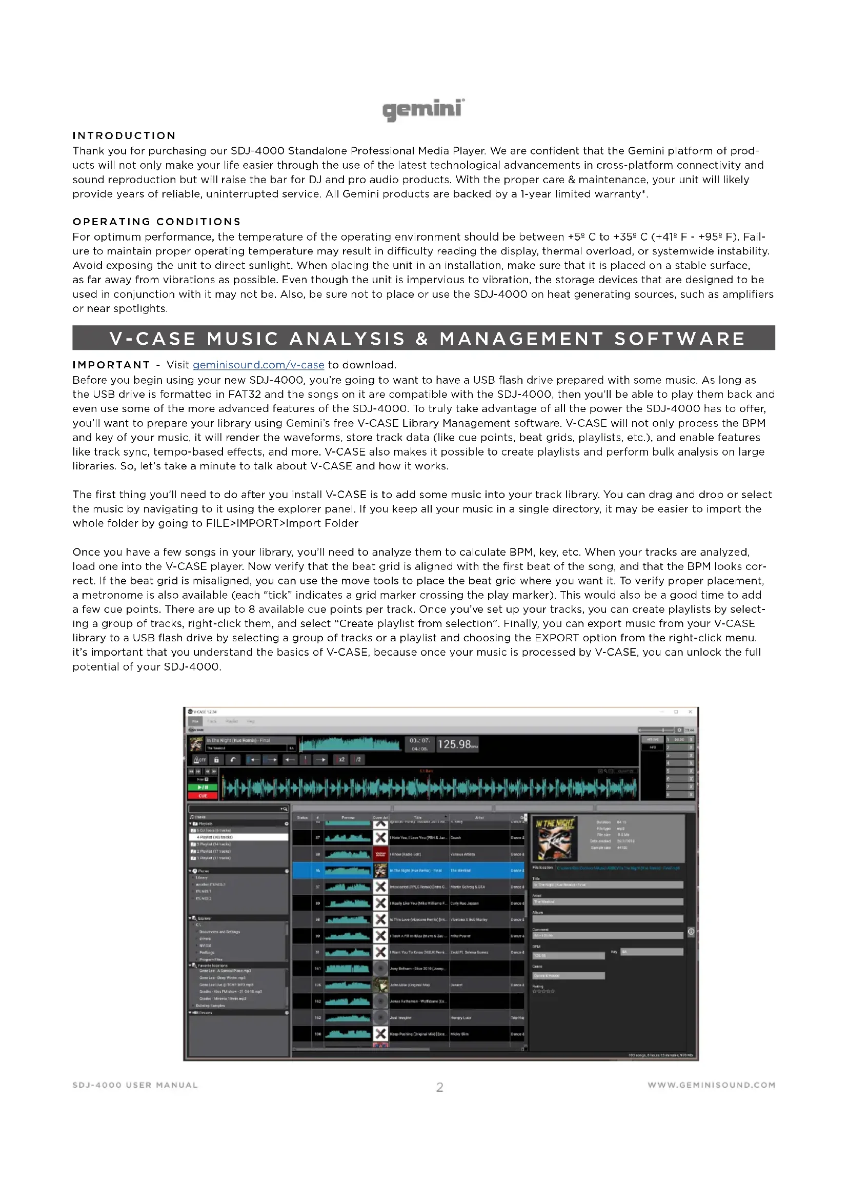
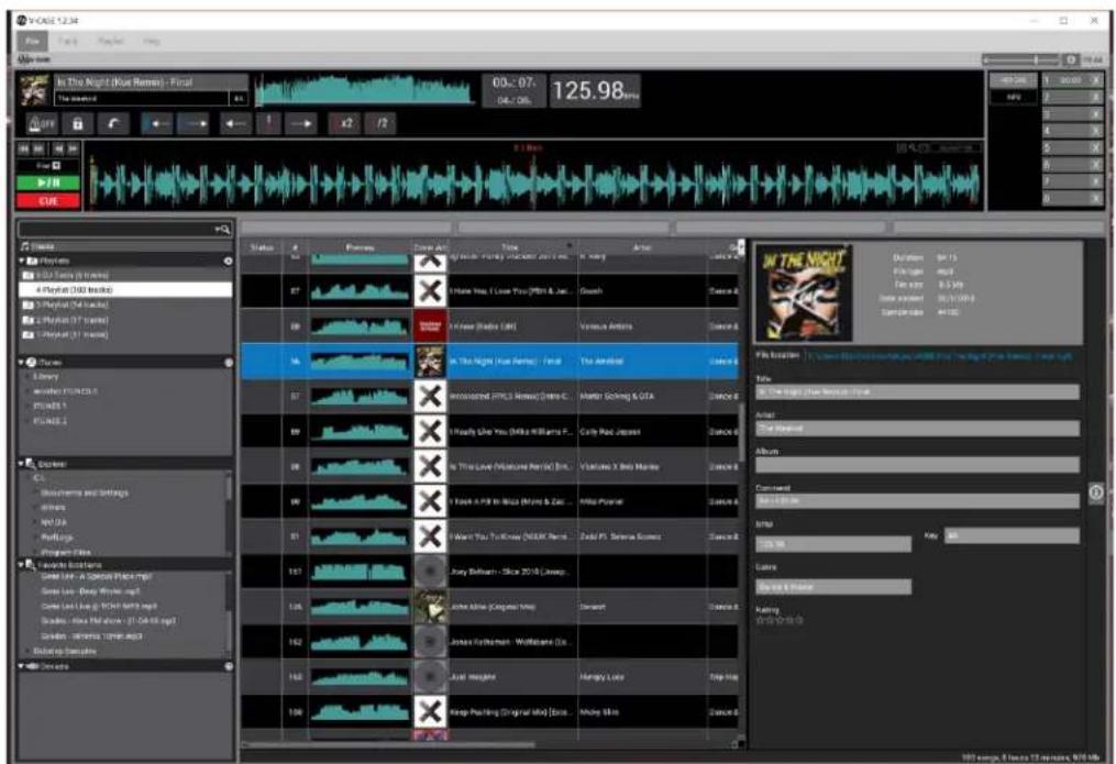
Before you begin using your new SDJ-4000, you're going to want to have a USB flash drive prepared with some music. As long as the USB drive is formatted in FAT32 and the songs on it are compatible with the SDJ-4000, then you'll be able to play them back and even use some of the more advanced features of the SDJ-4000. To truly take advantage of all the power the SDJ-4000 has to offer, you'll want to prepare your library using Gemini's free V-CASE Library Management software. V-CASE will not only process the BPM and key of your music, it will render the waveforms, store track data (like cue points, beat grids, playlists, etc.), and enable features like track sync, tempo-based effects, and more. V-CASE also makes it possible to create playlists and perform bulk analysis on large libraries. So, let's take a minute to talk about V-CASE and how it works.
The first thing you'll need to do after you install V-CASE is to add some music into your track library. You can drag and drop or select the music by navigating to it using the explorer panel. If you keep all your music in a single directory, it may be easier to import the whole folder by going to FILE>IMPORT>Import Folder
Once you have a few songs in your library, you'll need to analyze them to calculate BPM, key, etc. When your tracks are analyzed, load one into the V-CASE player. Now verify that the beat grid is aligned with the first beat of the song, and that the BPM looks correct. If the beat grid is misaligned, you can use the move tools to place the beat grid where you want it. To verify proper placement, a metronome is also available (each "tick" indicates a grid marker crossing the play marker). This would also be a good time to add a few cue points. There are up to 8 available cue points per track. Once you've set up your tracks, you can create playlists by selecting a group of tracks, right-click them, and select "Create playlist from selection". Finally, you can export music from your V-CASE library to a USB flash drive by selecting a group of tracks or a playlist and choosing the EXPORT option from the right-click menu. It's important that you understand the basics of V-CASE, because once your music is processed by V-CASE, you can unlock the full potential of your SDJ-4000.
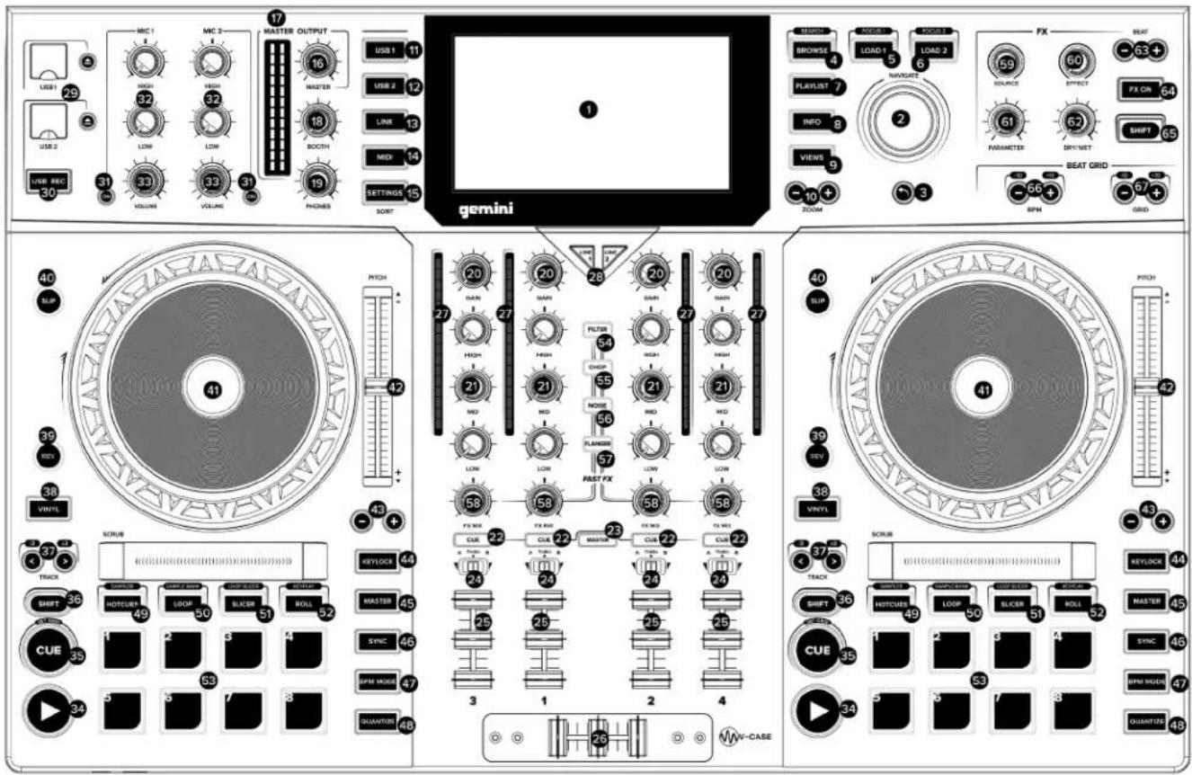
LAYOUT

FEATURES
- HD DISPLAY - This full-color display shows information relevant to the SDJ-4000's current operation. Touch the hardware controls to control the SDJ-4000's interface.
- NAVIGATE KNOB - Turn this knob to navigate through lists. Press the knob to move forward in navigation.
- BACK - Press this button to move back in navigation.
- BROWSE (SEARCH) - Press to toggle between track list and waveform display. Press Shift + Browse to enter track search mode.
- LOAD 1 (FOCUS) - Press to load a track to deck 1. Press Load 1 + Shift to focus on deck 1 during beat grid and BPM adjustments.
- LOAD 2 (FOCUS) - Press to load a track to deck 2. Press Load 2 + Shift to focus on deck 2 during beat grid and BPM adjustments.
- PLAYLIST - Press this to access the playlist menu. You
can see user created playlists, sample playlists, and history playlists.
- INFO - Press to see more information about a track, including album art, track rating, etc.
- VIEWS - Press to change waveform from stacked horizontal waveforms to vertical waveforms ideal for scratching.
- ZOOM - Press to zoom in and out of waveform.
- USB 1 - Press to access your music on USB 1
- USB 2 - Press to access your music on USB 2.
- LINK - Press to access any linked libraries including V-CASE if connected directly to a PC or MAC.
- MIDI - Press twice to enter MIDI mode and use the SDJ-4000 as a controller.
- SETTINGS (SEARCH) - Press to access the SDJ-4000 settings menu. Here you can control a variety of variables to make the SDJ-4000 your own. Press Settings + Shift to ac-
gemini®
cess the search menu while in browser mode. Here you can type a string to find specific tracks in larger libraries.
-
MASTER LEVEL - Turn this knob to adjust the volume level of the Master Outputs.
-
MASTER VU - These LEDs display the audio signal level of the master output.
-
BOOTH LEVEL - Turn this knob to adjust the volume level of the Booth Outputs.
-
PHONES LEVEL - Adjusts the volume of the headphones.
-
CHANNEL LEVEL - Turn this knob to adjust the level of the pre-fader, pre-EQ audio signal for the channel.
-
CHANNEL EQ - Turn these knobs to boost or cut the high, mid-range, and low frequencies for the channel.
-
CHANNEL CUE - Press this button to send the channel's pre-fader signal to the headphones' cue channel.
-
MASTER CUE - Press this button to send the master's pre-fader signal to the headphones' cue channel.
-
CROSSFADER ASSIGN - Routes the audio playing on the corresponding channel to either side of the crossfader (A or B), or bypasses the crossfader and sends the audio directly to the program mix (center, Thru)
-
CHANNEL FADER - Use this fader to adjust the channel's volume level.
-
CROSSFADER - Use this crossfader to mix between channels assigned to the left and right sides of the crossfader.
-
CHANNEL VU - These LEDs display the audio signal level of the channel.
-
INPUT SELECTOR - Set these buttons to the desired audio source from this channel: USB or Line (a device connected to the inputs on the rear panel).
-
USB 1/2 PORTS AND EJECT - Insert a USB thumb drive to access your music. Press and hold EJECT to safely eject the USB device.
-
USB 2 RECORD - Press USB REC to record your set to USB 2. Press again to stop recording. You can access music on USB 2 and record at the same time.
-
MICROPHONE ON - Press this button to activate/deactivate the microphones.
-
MICROPHONE EQ - Turn these knobs to boost or cut the high and low frequencies for the corresponding microphones.
-
MICROPHONE VOLUME - Turn these knobs to adjust the volume levels of the corresponding microphone inputs.
-
PLAY/PAUSE - This button pauses or resumes playback.
-
CUE (SET GRID) - During playback, press this button to return the track to the initial cue point and stop play-back. (To move the initial cue point, make sure the track is paused, move the platter to place the audio playhead at the desired location, and then press this button.) If the deck is paused, press and hold this button to temporarily play the track from the initial cue point. Release the button to return the track to the initial cue point and pause it. To continue playback without returning to the initial cue point, press and hold this button and then press and hold the Play button, and then release both buttons. Press and SHIFT + CUE to set the beat grid.
-
SHIFT - Press and hold this button to access secondary functions of other controls.
-
TRACK SKIP (/2 & X2) - Press either of these buttons to skip to the previous or next track. Press the Previous Track button in the middle of a track to return to the beginning of the track. SHIFT + TRACK SKIP increases and decreases the size of the playing loop.
-
VINYL - Press this button to activate/deactivate a "vinyl mode" for the platter. When activated, you can use the platter to "scratch" the track as you would with a vinyl record.
-
REVERSE - Press this button to activate/deactivate reverse playback.
-
SLIP - Press this button to enable or disable Slip Mode. In Slip Mode, you can jump to cue points, trigger loop rolls, or use the platters, while the track's timeline continues. In other words, when you stop the action, the track will resume normal playback from where it would have been if you had never done anything (i.e., as if the track had been playing forward the whole time).
-
PLATTER - This capacitive, touch-sensitive platter controls the audio playhead when the wheel is touched and moved. When the Vinyl button is on, move the platter to "scratch" the track as you would with a vinyl record. When the Vinyl button is off (or if you are touching only the side of the platter), move the platter to temporarily adjust the track's speed.
-
PITCH FADER - Move this fader to adjust the speed (pitch) of the track. You can adjust its total range with the Pitch Bend buttons.
-
PITCH BEND - Press and hold one of these buttons to momentarily reduce or increase (respectively) the speed of the track.
-
KEYLOCK - Press to activate keylock. Keylock fixes the pitch of the song while letting you alter the tempo.
-
MASTER - Press play on one deck to automatically assign it master. You can use the MASTER buttons to manually change the status of the deck. Only one deck can be assigned MASTER at any time.
-
SYNC - Press to activate SYNC mode on a deck. Pressing with SYNC the deck to the MASTER.
-
BPM MODE - Press to rotate through 3 possible BPM modes. AUTOBPM - BPM is set in V-CASE or using the onboard processor. ID3 - BPM value is taken from the ID3 tag. MANUAL - BPM can be set using the Browse rotary.
-
QUANTIZE - Press to activate quantize. The QUANTIZE button allows track events (like hotcues, loops, etc.) to be placed in locations that are musically pleasing. Without quantize, it is possible for the user to place (for instance) a hotcue in a position "between beats", which means when they are triggered they sound incorrect. The QUANTIZE feature forces events to snap to the closest beat, creating a more musical result.
-
HOT CUE (SAMPLER) - In HOT CUE mode you can use each pad to jump to an assigned hot cue point. Press SHIFT + HOT CUE to enter SAMPLER mode. In SAMPLER mode, the performance pads turn into a sampler, allowing the DJ to play back prepared samples of any length. Samples are stored on the MSD and are recalled as a playlist.
-
LOOP (SAMPLE BANK) - In LOOP MODE, each of the 8 performance pads are all associated with a specific value of loop. Pressing one of the pads will generate a loop automatically that is the length specified on the pad. Only 1 loop can be active at any given time. If multiple LOOP buttons are pressed, then the last pressed button takes precedence. Press SHIFT + LOOP to enter SAMPLE BANK mode, in this mode you can select one of 8 Sample Banks by pressing either of the pads.
-
SLICER (LOOP SLICER) - SLICER chops up the playing song into 8 beat synchronized segments and assigns each one to a PERFORMANCE PAD. Each slice of the song plays from start to finish in order, lighting each corresponding pad as they play. Press SHIFT + SLICER to enter LOOP
gemini®
SLICER mode. LOOP SLICER mode works almost exactly like SLICE mode, except that instead of the play marker moving forward in the song at the end of 8 slices, it sets a loop when the mode is engaged and returns to the beginning of the loop when the 8th slice is finished playing.
-
ROLL (KEYPLAY) - This pad mode creates a momentary loop that repeats as long as the pad is held down, and also engages its own SLIP mode - so that when the loop is released playback returns to the buffered position and not the position of the play marker at the release of the loop. Press SHIFT + ROLL to enter KEYPLAY mode. Press each pad to adjust the playing song by an octave. In this mode, each of the 8 pads represents a note, with 8 notes making an octave. There are also 8 scales available to the user in KEYPLAY mode (through pressing SHIFT + one of the pads) - Major, Minor, Major Pentatonic, Blues, Mixolydian, Chromatic, Dorian, and Lydian.
-
PERFORMANCE PADS - The PERFORMANCE PAD section is comprised of the 8 large pads and 4 smaller buttons that are positioned directly underneath the PLATTER in each deck section. The function of the 8 large pads is determined by the mode the pad section is in, and the modes are selected by the 4 smaller buttons (and by the SHIFT button).
-
FAST FX FILTER - The FILTER effect is a typical dual pole filter effect. When the knob is at the 12 o'clock position, there is no effect at all. Turning the knob to the right engages a high-pass filter, which increases the depth of the filter as well as the cut off frequency as the knob rotates clockwise. Turning the knob left engages a low-pass filter, which increases the depth and cutoff frequency as the knob rotates counter clockwise.
-
FAST FX CHOP - When the FX knob moves clockwise, the effect is CHOP only. The knob effects the time it takes for the gate to open and close. Turning the knob counterclockwise produces the exact same gater effect as the clockwise rotation, but also adds a reverb to the gate effect.
-
FAST FX NOISE - The NOISE effect is a noise generator. When the knob is at the 12 o'clock position, the effect is not heard. Turning the knob to the right gradually adds noise to the channel audio, while also increasing the pitch of the noise. Turning the knob left does the same, adding noise and increasing the pitch of the noise - but it also adds reverb after the noise and channel audio.
-
FAST FX FLANGER - A flanger is a modulation effect where the delayed signal, which is added back to an equal amount of the dry signal, is modulated by using an LFO. Turning the knob to the right regulates flanger parameter. Turning the knob to the left introduces not only a flanger, but also adds a lowpass filter to the mix.
-
FAST FX - Turn this knob to control the effect selected by the FAST FX buttons.
-
MAIN FX SOURCE - Use this knob to choose the audio source you want to apply an FX to.
-
FX SELECT - Use this knob to choose which FX to use.
-
FX PARAMETER - Use this knob to adjust the effect parameter.
-
FX DRY/WET - Turn this knob to adjust the wet/dry mix of the effects
-
FX BEAT/TIME - Press either of these buttons to decrease or increase the rate of time-based effects on that deck.
-
FX ON - Press this buttons to enable or disable FX.
-
SHIFT - Press and hold this button to access secondary functions of other controls.
-
BPM ADJUST - Press these buttons to adjust your BPM in small increments or press SHIFT to adjust in large increments.
-
GRID ADJUST - Press these buttons to move our Beat Grid in small increments or press SHIFT to adjust in large increments.
-
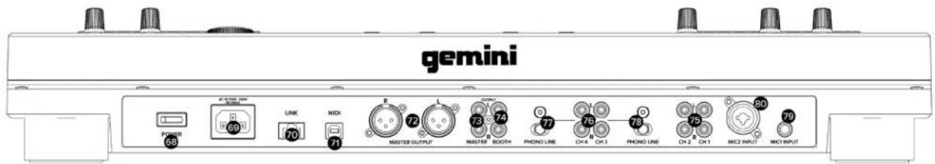
POWER BUTTON - Press this button to power on. Power on only after you have connected all of your input devices and before you power on your amplifiers and loudspeakers.
-
POWER INPUT - Use the included power cable to connect this input to a power outlet.
-
LINK PORT - Use a standard Ethernet cable to connect this port to a computer, switch or additional SDJ or MDJ player to share library resources.
-
MIDI PORT - Use a standard USB cable to connect this USB port to an available USB port on your computer. This connection sends and receives MIDI messages.
-
MASTER XLR BALANCED OUTPUT - Use standard XLR cables to connect these outputs to loudspeakers or an amplifier system. Use the Master knob on the top panel to control the volume level.
-
MASTER RCA UNBALANCED OUTPUT - Use standard RCA cables to connect these outputs to loudspeakers or an amplifier system. Use the Master knob on the top panel to control the volume level.
-
BOOTH RCA UNBALANCED OUTPUT - Use standard RCA cables to connect these outputs to loudspeakers or an amplifier system. Use the Booth knob on the top panel to control the volume level.
-
CH1/CH2 LINE INPUT - Use standard RCA cables to connect these line-level inputs to an external audio source.
-
CH3/CH4 PHONO/LINE INPUT - Use standard RCA cables to connect these line-level or phono-level inputs to an external audio source.
-
CH4 PHONO/LINE SWITCH & GROUND POST - Flip the switch to the appropriate position depending on what is connected. If using phono-level turntables with a grounding wire, connect the grounding wire to these terminals. If you experience a low "hum" or "buzz", this could mean that your turntables are not grounded.
-
CH3 PHONO/LINE SWITCH & GROUND POST - Flip the switch to the appropriate position depending on what is connected. If using phono-level turntables with a grounding wire, connect the grounding wire to these terminals. If you experience a low "hum" or "buzz", this could mean that your turntables are not grounded.
-
MIC 1 INPUT - Use standard 1/4" (6.35 mm) cables (not included) to connect standard dynamic microphones to these inputs. Use the Mic 1 Level knobs on the top panel to control the volume level.
-
MIC 2 INPUT - Use standard XLR or 1/4" (6.35 mm) cables (not included) to connect standard dynamic microphones to these inputs. Use the Mic 2 Level knobs on the top panel to control the volume level.
-
HEADPHONES (NOT SHOWN) - Located on front of SDJ. Connect your 1/4" or 1/8" (6.35 mm or 3.5 mm) headphones to this output for cueing and mix monitoring. The headphone volume is controlled using the Phones Level knob.
PERFORMANCE PAD DETAILS
The PERFORMANCE PAD section is comprised of the 8 large pads and 4 smaller buttons that are positioned directly underneath the PLATTER in each deck section. The function of the 8 large pads is determined by the mode the pad section is in, and the modes are selected by the 4 smaller buttons (and by the SHIFT button).
HOTCUES
This mode allows the user to record and recall up to 8 locations in any track. Each stored location is called a CUE POINT (or often a "hot cue"). Only one cue can be active at a time. Pressing multiple buttons at the same time will result in the last pressed CUE being active. To create a hotcue, put the pads into CUE mode by pressing the CUE button in the top row. The CUE button will light GREEN to show that CUE mode is active. Buttons 1-8 will light YELLOW to indicate to the user that buttons 1-8 have no cues stored for the currently loaded song (note that cue points are stored in the track metadata, and load when each track loads). To set a CUE, place the play marker at the desired location in the track and press one of the CUE buttons 1-8. That first press will record the cue location and turn the button to green (to indicate that a CUE has been stored at that location). Each subsequent press will jump the play marker to the stored location AND start playback immediately. To delete a stored CUE point, press and hold the SHIFT button while pressing the CUE button corresponding to the CUE point you would like to delete. The button will switch color from green back to yellow, indicating that the button is ready to store a new CUE point. If the user has the QUANTIZE feature turned on, then the behavior of setting a cue point is modified slightly. Instead of the cue point being dropped precisely at the play marker, QUANTIZE will force the cue point to move instead to the closest beat grid marker that corresponds to the QUANTIZE value. For example, if the user drops a cue in the middle of 2 beats, and the QUANTIZE value is set to 1 beat, then the cue will be forced to the closest beat INSTEAD of being put in the middle of 2 beats. In SLIP mode, the behavior of the cues changes. When a CUE is pressed, the play marker jumps to the stored location like normal, but it only plays while the user holds down the pad. When the user lets go of the pad, playback returns to the position set in the SLIP buffer.
LOOPS
In LOOP MODE, each of the 8 performance pads are all associated with a specific value of loop. Pressing one of the pads will generate a loop automatically that is the length specified on the pad. Only 1 loop can be active at any given time. If multiple LOOP buttons are pressed, then the last pressed button takes precedence. To put the pads into LOOPS mode, press the LOOPS button at the top of the pad array. The button will light green, indicating to the user that the pads are now in LOOPS mode. The 8 pads will light yellow to indicate that no loop is currently active. Each of the pads is associated with a specific beat, ranging from 1/8th of a beat to 16 beats. Pressing a pad - pad 7 for instance - will create an automatic loop starting at the position of the play marker when the button was pressed and out for 8 beats. When a loop is active, the corresponding button will light green. Pressing the button again will exit the loop and turn the button yellow. If a different button is pressed while a loop is active, then the loop size will change to the new value but keep the original starting point. If the new value is higher than the current value (for instance, the user changes from 2 beats to 16) then the loop end point is moved, and play continues as normal. However, if the new value is SMALLER than the currently selected value, then the loop is RETRIGGERED from the same starting point, and the end point will be changed to the new value. When a loop is active, there will be a blue highlight in the moving waveform view like the image below. If the user has the QUANTIZE feature turned on, then the loop starting point may not drop when the user presses the button, but instead when the next closest quantize value is reached. When LOOP is used while the deck is in SLIP mode, the behavior is very much like ROLL mode, except that the loop value latches down when pressed. The user must press the LOOP button again to release the play marker from the loop. However once released, the play marker goes to the position set by the SLIP buffer.
SAMPLER and SAMPLE BANK
In SAMPLES mode, the performance pads turn into a sampler, allowing the DJ to play back prepared samples up to 15 seconds. Samples are stored on the MSD and are recalled as a playlist. To create a ONE-SHOT sample, first put the pads into ONE SHOT mode by pressing the ONE SHOT button at the top of the pad array. The ONE-SHOT button will light green to indicate that the mode has been selected. On pads 1-8, a yellow light indicates that there is not a sample stored, and green indicates a stored sample on that pad. To begin recording, press any yellow pad and hold it down for as long as you want the sample to record (up to 15 seconds). While recording, the pad will illuminate red to indicate a recording is taking place. Samples are stored with an automatically generated name in 44.1/16 .wav format in the specified location. Users can select the location in SETTINGS>SAMPLER SOURCE FOR DECK X - where the choices are USB1, USB2, or MEM. Storing the files to USB 1 or 2 results in the file being saved into the GEMINI>SAMPLES folder and being recalled when that MSD is loaded into the SDJ-4000. If the files are stored into the MEM location, they are loaded into device memory and are lost when the SDJ-4000 is power cycled. A playlist can also be used to load samples into the ONE-SHOT pads. In V-CASE, if the user goes through the process of selecting files to create a playlist, then selects the CREATE PLAYLIST FROM SELEC-TION option, a window will open asking the user to name the new playlist. In that window, there will also be a checkbox with the word ONE-SHOT next to it. Checking that box will save the playlist as a ONE-SHOT playlist. PLEASE NOTE that selecting this option will only take the first 8 files selected and ignore anything else that was added to the playlist. Songs are numbered in the order they were added to the playlist, and samples 1-8 load into their corresponding pads. On the SDJ-4000 BROWSE menu, there will be a new entry called SAMPLE PLAYLIST. When the user navigates into the SAMPLE PLAYLIST directory, any playlist created as a ONE-SHOT playlist will appear here. The user can use the jog to highlight these playlists to see what is in each of them, or they can press the LOAD 1 or LOAD 2 buttons to load that playlist into the ONE-SHOT pads for either deck. To delete a sample from a ONE-SHOT pad, the user must press and hold the SHIFT button and then press the pad corresponding to the sample to be erased. The pad will then turn color from green to yellow, indicating that the pad is now "empty" and ready to record a new sample.
gemini®
ROLL
This pad mode creates a momentary loop that repeats as long as the pad is held down, and also engages its own SLIP mode - so that when the loop is released playback returns to the buffered position and not the position of the play marker at the release of the loop. Like in LOOP mode, the pads all have defined values printed on each of them. This value defines the ROLL value. Pressing pad 2 results in a 14 beat loop running, where pad 4 creates a 1 beat loop. To create a loop ROLL, first set the pad section into ROLL mode by pressing the ROLL button at the top of the pad array. It will light green to indicate that the pads are now in ROLL mode. Pads 1-8 will light yellow to indicate that no loop ROLL is currently active. With a song playing, pressing and holding one of the pads will generate a loop repeating at the value specified on the pad. This action will also engage the SLIP buffer, keeping an unaltered copy of the song playing in memory. When the pad is released, playback returns at the location of the SLIP buffer. PLEASE NOTE that when loop ROLL is active, the SLIP button will flash, indicating the use of the SLIP buffer. This will happen even if the song was already in SLIP mode BEFORE loop ROLL was engaged.
SLICER
SLICER chops up the playing song into 8 beat synchronized segments and assigns each one to a PERFORMANCE PAD. Each slice of the song plays from start to finish in order, lighting each corresponding pad as they play. Slices are always aligned to the beat grid, so slice 1 is always "on the one" of a measure or phrase. If the user enters SLICER mode on beat 6 of a phrase, the SLICER will start with the slice for beat 6. Like in SLIP mode, the slice counter is always running with the play marker independently of user input. Once the SLICER gets finished laying slice 8, the next 8 slices are loaded into the SLICER and mapped to the pads. When the user presses a pad, the slice associated with that pad will play until the end of that slice. Slices are re-triggered on every press of the pad. Any interaction by the user is heard INSTEAD of normal playback, however playback returns to normal once user interaction ends. In this way, the SLICER is a lot like LOOP+SLIP or ROLL modes. If the user holds the pad down, that sample is repeated until the pad is released. To engage the SLICER, press SLICER. All pads will turn yellow except the currently playing slice, which will light green. If the user presses a slice, that slice turns dark blue to show it's a user triggered event, and the slice counter moves on in light blue. It is also possible to change the value of each slice by using the SHIFT+TRACK </> buttons - which halve or double the current value.
LOOP SLICER
LOOP SLICER mode works almost exactly like SLICE mode, except that instead of the play marker moving forward in the song at the end of 8 slices, it sets a loop when the mode is engaged and returns to the beginning of the loop when the 8th slice is finished playing. To enter LOOP SLICER mode, press SHIFT + SLICER. The SLICER button will turn pink, indicating the secondary mode for the SLICER button is active. Pads will light yellow, except the pad that represents the current position of the slice counter - which will be red. If the user presses a slice, that slice turns dark blue to show it's a user triggered event, and the slice counter moves on in light blue.
KEYPLAY
Most of the other pad modes manipulate the play marker, but KEYPLAY is different in that it instead manipulates the key of the playing track. To enter KEYPLAY mode, press SHIFT plus the ROLL button. The ROLL button will light pink, indicating that it has entered its shifted mode. The pads will all light yellow. In this mode, each of the 8 pads represents a note, with 8 notes making an octave. There are also 8 scales available to the user in KEYPLAY mode (through pressing SHIFT + one of the pads) - Major, Minor, Major Pentatonic, Blues, Mixolydian, Chromatic, Dorian, and Lydian. In this example, we are working with a song that is in C Major, and KEYPLAY is set to a MAJOR scale. The values in blue would be the resulting note if the user pressed the associated pad. The notes ascend from the root note (pad 1) to an octave above (pad 8). Available scales are selected by the user by pressing SHIFT and one of the pads. When the user changes scale, the new selected scale will flash in red to let the user know of the setting change.
| MAJOR PAD 1 MIXOLYDIAN PAD 5 | ||
| MINOR PAD 2 CHROMATIC PAD 6 | ||
| MAJOR PENTATONIC® PAD 3 DORIAN PAD 7 | ||
| BLUES® PAD 4 LYDIAN PAD 8 |
* Please note that these 2 scales do not have 7 steps. In these 2 cases, the pads will represent a little more than an octave.
INTRODUCCIÓN
DISEÑO

CARACTERISTICAS
DISPOSITION


TRAITS
LAYOUT


EIGENSCHAFTEN
Warranty and Repair:
All Gemini products are designed and manufactured to the highest standards in the industry. With proper care and maintenance, your product will provide years of reliable service.
LIMITED WARRANTY
A. Gemini guarantees its products to be free from defects in materials and workmanship for One (1) year from the original purchase date. Exceptions: Laser assemblies on CD Players, cartridges, and crossfaders are covered for 90 days.
B. This limited warranty does not cover damage or failure caused by abuse, misuse, abnormal use, faulty installation, improper maintenance or any repairs other than those provided by an authorized Gemini Service Center.
C. There are no obligations of liability on the part of Gemini for consequential damages arising out of or in connection with the use or performance of the product or other indirect damages with respect to loss of property, revenues, of profit, or costs of removal, installation, or reinstallation. All implied warranties for Gemini, including implied warranties for fitness, are limited in duration to One (1) year from the original date of purchase, unless otherwise mandated by local statutes.
RETURN/REPAIR
A. In the U.S.A., please call our helpful Customer Service Representatives at (732) 346-0061, and they will be happy to give you a Return Authorization Number (RA#) and the address of an authorized service center closest to you.
B. After receiving an RA#, include a copy of the original sales receipt, with defective product and a description of the defect. Send by insured freight to: Gemini and use the address provided by your customer service representative. Your RA# must be written on the outside of the package, or processing will be delayed indefinitely!
C. Service covered under warranty will be paid for by Gemini and returned to you. For non-warrantied products, Gemini will repair your unit after payment is received. Repair charges do not include return freight. Freight charges will be added to the repair charges.
D. On warranty service, you pay for shipping to Gemini, we pay for return shipping within the continental United States. Alaska, Hawaii, Puerto Rico, Canada, Bahamas, and the Virgin Islands will be charged for freight.
E. Please allow 2-3 weeks for return of your product.
Under normal circumstances your product will spend no more than 10 working days at Gemini. We are not responsible for shipping times.
Gemini
Worldwide Headquarters
458 Florida Grove Road
Perth Amboy, NJ 08861 USA
Tel: (732) 346-0061
Register your product online at GEMINISOUND.COM to be stay up to date with product updates!
gemini®
In the USA: if you experience problems with this unit, call 732-346-0061 for Gemini customer service. Do not attempt to return this equipment to your dealer.
Parts of the design of this product may be protected by worldwide patents. Information in this manual is subject to change without notice and does not represent a commitment on the part of the vendor. Gemini shall not be liable for any loss or damage whatsoever arising from the use of information or any error contained in this manual. No part of this manual may be reproduced, stored in a retrieval system or transmitted, in any form or by any means, electronic, electrical, mechanical, optical, chemical, including photocopying and recording, for any purpose without the express written permission of Gemini It is recommended that all maintenance and service on this product is performed by Gemini or its authorized agents. Gemini will not accept liability for loss or damage caused by maintenance or repair performed by unauthorized personnel.
Worldwide Headquarters
458 Florida Grove Road
Perth Amboy, NJ 08861 USA
Tel: (732)346-0061
gemini®