CDM4000BT - DJ Equipment GEMINI - Free user manual and instructions
Find the device manual for free CDM4000BT GEMINI in PDF.
| Product Type | Professional CD player with mixer console |
| Brand | Gemini |
| Model | CDM4000BT |
| Dimensions | 482.6 x 88.9 x 254 mm (19 x 3.5 x 10 inches) |
| Power Supply | AC 115/230 V, 60/50 Hz |
| Sampling Frequency | 44.1 kHz |
| Bandwidth | 20 Hz - 20 kHz |
| Total Harmonic Distortion | < 0.05 % |
| Signal-to-Noise Ratio | 85 dB |
| Output Level | 2.0 ± 0.2 V RMS |
| CD Compatibility | Audio CD and CD-R (12 cm and 8 cm) |
| Time Display | Elapsed time, remaining time, total remaining time (minutes - seconds - frames) |
| Pitch Adjustment | ± 12 % (linear fader) |
| Main Features | Anti-shock memory, jog wheel, perfect loop, reloop, fader start, CUE monitoring, playlist creation (PGM) |
| Inputs | 2 x RCA (CD/Line), XLR and 6.35 mm jack microphone, Phono/Line auxiliary, USB/SD |
| Outputs | Master RCA unbalanced, Master XLR balanced, record RCA, 6.35 mm jack headphone |
| Maintenance and Cleaning | Slightly damp cloth, no chemical solvents; keep trays closed |
| Safety | Do not open the device, unplug during storms, avoid liquids, do not block ventilation slots |
| Spare Parts and Repairability | User-replaceable crossfader (model RG-45), other genuine parts recommended |
Frequently Asked Questions - CDM4000BT GEMINI
User questions about CDM4000BT GEMINI
0 question about this device. Answer the ones you know or ask your own.
Ask a new question about this device
Download the instructions for your DJ Equipment in PDF format for free! Find your manual CDM4000BT - GEMINI and take your electronic device back in hand. On this page are published all the documents necessary for the use of your device. CDM4000BT by GEMINI.
USER MANUAL CDM4000BT GEMINI
CDM-4000
CD/MP3/USB DJ MEDIA PLAYER
gemini ^ DJ
PLEASEREADBEFOREUSINGAPPLIANCE IMPORTANTWARNINGANDSAFETYINSTRUCTIONS!


RISKOFELECTRIC SHOCKDONOT OPEN!


CAUTION: This product satisfies FCC regulations when shielded cables and connectors are used to connect the unit to other equipment. To prevent electromagnetic interference with the electric appliance such as radios and televisions, uses shielded cables and connectors for connections.
The exclamation point within an equilateral triangle is intended to alert the user to the presence of important operating and maintenance (servicing) instructions in the literature accompanying the appliance.
The lightening flash with arrowhead symbol, within an equilateral triangle, is intended to alert the user to the presence of uninsulated "dangerous voltage" within the product's enclosure that maybe of sufficient magnitude to constitute risk of electric shock topersons.
READ INSTRUCTIONS: All the safety and operating instructions should be read before the product is operated.
RETAIN INSTRUCTIONS: The safety and operating instructions should be retained for future reference.
HEED WARNINGS: All warnings on the product and in the operating instructions should be adhered to.
FOLLOWINSTRUCTIONS: Alloperating and use instruction should be followed.
CLEANING: The product should be cleaned only with a polishing cloth or a soft dry cloth. Never clean with furniture wax, benzine, insecticides or other volatile liquids since they may corrode the cabinet.
ATTACHMENTS: Do not use attachments not recommended by the product manufacturer as they may cause hazards.
WATER AND MOISTURE: Do not use this product near water, for example, near a bathtub, wash bowl, kitchen sink, or laundry tub; in a wet basement; or near a swimming pool; and the like.
ACCESSORIES: Do not place this product on an unstable cart, stand, tripod, bracket, or table. The product may fall, causing serious injury to a child or adult, and serious damage to the product. Use only with a cart, stand, tripod, bracket, or table recommended by the manufacturer, or sold with the product. Any mounting of the product should follow themanufacturer'sinstructions,andshoulduseamountingaccessoryrecommendedbythemanufacturer.
CART: A product and cart combination should be moved with care. Quick stops, excessive force, and uneven surfaces may cause the product and cart combination to overturn.SeeFigureA.
VENTILATION: Slots and openings in the cabinet are provided for ventilation and to ensure reliable operation of the product and to protect it from overheating, and these openings must not be blocked or covered. The openings should never be blocked by placing the product on a bed, sofa, rug, or other similar surface. This product should not be placed in a built-in installation such as a bookcase or rack unless proper ventilation is provided or the manufacturer's instructions have been adhered to.
POWER SOURCES: This product should be operated only from the type of power source indicated on the marking label. If you are not sure of the type of power supply to your home, consul your product dealer or local power company.
LOCATION: The appliances should be installed in a stable location.
NON-USE PERIODS: The power cord of the appliance should be unplugged from the outlet when left unused for a long period of time.
GROUNDINGORPOLARIZATION:
- If this product is equipped with a polarized alternating current line plug (a plug having one blade wider than the other), it will fit into the outlet only one way. This is a safety feature. If you are unable to insert the plug fully into the outlet, try reversing the plug. If the plug should still fail to fit, contact your electrician to replace your obsolete outlet. Do not defeat the safety purpose of the polarized plug.
- If this product is equipped with a three-wire grounding type plug, a plug having a third (grounding) pin, it will only fit into a grounding type power outlet. This is a safety feature. If you are unable to insert the plug into the outlet, contact your electrician to replace your obsolete outlet. Donotdefeatthesafetypurposeofthegroundingtypeplug.

Fig.A
POWER-CORD PROTECTION: Power-supply cords should be routed so that they are not likely to be walked on or pinched by items placed upon or against them, paying particular attention to cords at plugs, conveniencereceptacles, and the point where they exit from the product.
OUTDOOR ANTENNA GROUNDING: If an outside antenna or cable system is connected to the product, be sure the antenna or cable system is grounded so as to provide some protection against voltage surges and built-up static charges. Article 810 of the National Electrical Code, ANSI/NFPA 70, provides information with regard to proper grounding of the mast and supporting structure, grounding of the lead-in wire to an antenna discharge unit, size of grounding conductors, location of antenna-discharge unit, connectiontogroundingelectrodes, and requirementsforthegroundingelectrode. SeeFigureB.
LIGHTNING: For added protection for this product during a lightening storm, or when it is left unattended and unused for long periods of time, unplug it from the wall outlet and disconnecttheantennaorcablesystem. This will prevent damage to the product duetolightening and power-lines surges.
POWER LINES: An outside antenna system should not be located in the vicinity of overhead power lines or other electric light or power circuits, or where it can fall into such power lines or circuits. When installing an outside antenna system, extreme care should be taken to keep from touchingsuchpowerlinesorcircuitsascontactwiththemmightbefatal.
OVERLOADING: Do not overload wall outlets, extension cords, or integral convenience receptacles as this can result in a risk of fire or electric shock.
OBJECT AND LIQUID ENTRY: Never push objects of any kind into this product through openings as they may touch dangerous voltage points orshort-outpartsthatcouldresultinafireorelectricshock.Neverspilliquidofanykindontheproduct.
SERVICING: Do not attempt to service this product yourself as opening or removing covers may expose you to dangerous voltage or other hazards. Referallservicingtoqualifiedservicepersonnel.
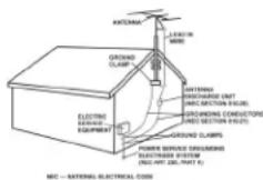
Fig.B
DAMAGE REQUIRING SERVICE: Unplug this product from the wall outlet and refer servicing to qualified service personnel under the following conditions:
- Whenthepower-supplycordorplugisdamaged.
- Ifliquidhasbeenspilled,orobjectshavefallenintotheproduct.
- If the product has been exposed to rain or water.
- If the product does not operate normally by following the operating instructions. Adjust only those controls that are covered by the operating instructions as an improper adjustment of other controls may result in damage and will often require extensive work by a qualified technician to restore the product to its normal operation.
- If the product has been dropped or damaged in any way.
- Whentheproductexhibitsadistinctchangeinperformance, thisindicatesaneedforservice.
REPLACEMENT PARTS: When replacement parts are required, be sure the service technician has used replacement parts specified by the manufacturer or have the same characteristics astheoriginal part. Unauthorized substitutions may result infire, electric shock, or other hazards.
SAFETY CHECK: Upon completion of any service or repairs to this product, ask the service technician to perform safety checks to determine that the product is in proper operating condition.
WALLORCEILINGMOUNTING: The product should not be mounted to a wall or ceiling.
HEAT: The product should be situated away from heat sources such as radiators, heat registers, stoves, or other products (including amplifiers) that produce heat.
Back
Posterior
Face Arrière
Rückseite
Front
Frontal
Face Avant
Vorderseite
TOP
Superior
Face Superieure
Oben
INTRODUCTION:
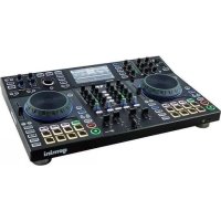
Congratulations on purchasing the Gemini CDM-4000 CD/USB/MP3 DJ Media Player. This unit is backed by a (1) year warranty. Prior to use, we urge that you understand all the instructions.
FEATURES:
Player Section:
- Audio CD & CD-R compatible
- Anti-shock using RAM buffer memory
- Large blue backlit LCD display
- 2 Selectable Jog modes Search & Pitch Bend
- Instant-start & cue with preview
- Fader-Start capability
- +10 track button for quick navigation
- Single & Continuous play modes
- One seamless loop per side with reloop
- Pitch bend via jog wheel or buttons +/- 16%
- Three mode time selection
- Frame accurate search
- Rubber jog wheels with finger grips
- Variable pitch control with a +/- 12% range
Mixer Section:
- 2-band EQ w/ Gain Control
- 1/4" headphone output
- XLR balanced outputs and 1/4" mic input
- Auxiliary Inputs for Line devices
SAFETY SPECIFICATIONS:
Laser Diode Properties
Material: Ga - Al - As
Wavelength: 755 - 815 nm (25°C)
Laser Output: Continuous Wave, max. 0.5 mW
PRECAUTIONS:
- Do not use this CD player at temperatures below 41^ F/ 5^ C or higher than 95^ F/ 35^ C.
- The apparatus should not be exposed to dripping or splashing, and no objects filled with liquids such as vases should be placed on the apparatus.
- Place the unit in a clean and dry location.
- Do not place the unit in an unstable location.
- When disconnecting the power cord from the AC outlet, always grasp by the plug. Never pull the power cord.
- To prevent electric shock, do not remove the cover or the bottom screws.
- There are NO USER SERVICEABLE PARTS INSIDE. Please refer to a qualified technician.
(IN THE USA - IF YOU EXPERIENCE PROBLEMS WITH THIS UNIT CALL GEMINI CUSTOMER SERVICE AT: 1(732) 346-0061. DO NOT ATTEMPT TO RETURN THIS EQUIPMENT TO YOUR DEALER)
- Do not use chemical solvents to clean the unit.
- Keep the laser pickup clean by keeping the tray closed.
- Keep this manual in a safe place for future reference.
CONNECTIONS:
1 POWER: Plug in the power cord of the CDM-4000.
2 LINE INPUTS: The CDM-4000 has 2 LINE RCA INPUTS. You may connect any line level device as described before (MP3, CD, Tape etc). Now you may plug the RCA's from your playable medium into each input to be connected to its respective CHANNELS.
3 MASTER RECORD RCA OUTPUT (UNBALANCED): The MASTER RCA output connects the mixer to your main amplifier using standard audio cables with RCA-type connectors. The RECORD RCA OUTPUT jacks can be used to connect the mixer to the record input of your recording unit, thus enabling you to record your mix with RCA cables.
4 MASTER XLR OUTPUT (BALANCED): Allows you to connect balanced XLR cables to MASTER OUTPUT of the CDM-4000 both the RCA and XLR outputs can be used at the same time but both are controlled via the same MASTER OUTPUT.
5 MIC (MICROPHONE) INPUTS: The main MIC or Microphone inputs are located at the back right hand corner and front panel of the CDM-4000 and will accept a 1/4" connector. You can control the volume for the mic (See CONTROLS) below.
6 HEADPHONE OUTPUTS: The HEADPHONE OUTPUT located front center of the CDM-4000 will accept any headphone with a standard 1/4" connector and/or adaptor and will allow you to CUE your music program before you play it, you can adjust the volume and PGM mix of the HEADPHONE (see CONTROLS) below.
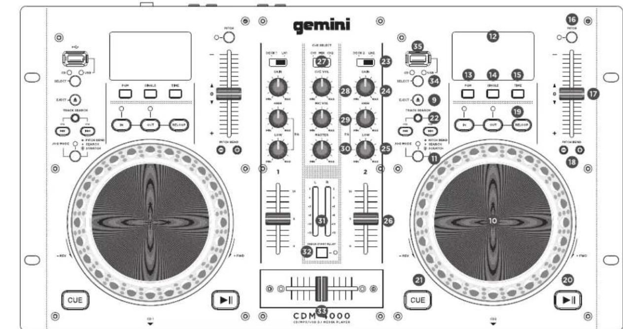
FUNCTIONS:
7 POWER: Once you have connected all your cables, you can turn the CDM-4000's POWER on by pressing the POWER button, pressing the button a second time will turn off the unit.
8 DISC TRAY: The DISC TRAY is where the CD is held during loading, unloading and playback, and holds both 12 cm and 8 cm CD's. (DO NOT FORCE THE CD TRAY TO CLOSE. EXCESSIVE FORCE WILL DAMAGE THE CD MECHANISM, USE THE OPEN AND CLOSE BUTTONS)
9 EJECT BUTTON: Pressing the EJECT BUTTON will open or close the DISC TRAY. The DISC TRAY will not eject in PLAY mode.
10 JOG WHEEL: In SEARCH MODE the JOG WHEEL can be used to search forward or backwards in the music track, as well as for fine adjustments to a CUE point in PAUSE mode. In PITCH BEND mode the JOG WHEEL will function the same as the PITCH BEND allowing you to speed up (FORWARD) or slow down (REWIND) the music clockwise being (FORWARD) and counter clockwise being (REWIND).
11 JOG MODE BUTTON: When the JOG MODE BUTTON is illuminated it indicates the JOG WHEEL is in SEARCH MODE, and when not illuminated it indicates that the JOG WHEEL is in PITCH BEND MODE.
12 DISPLAY: The DISPLAY shows the track number, pitch value, pitch bend, single, continue (for continuous play), play/pause modes, fast forward/reverse modes, loop mode, reloop mode, PGM, repeat modes, the playback display bar, and three different time displays. These times displays are TIME ELAPSED on the track, TIME REMAINING on the disc and TIME REMAINING on the track. Time is measured in minutes, seconds and frames.
13 PGM: Allows you to create a set playlist. To program a set list into the CDM-4000 memory, begin by stopping the unit from play and pressing PGM to begin the set list. Select a track by using the track selection button to scan to the first track to be placed in the set list. When you have selected the proper track press PGM and the CDM-4000 will be ready to set your next selection. Repeat the previous steps until you have completed your play list, then press play to begin the set list.
14 SINGLE: Pressing the SINGLE button engages SINGLE mode, in this mode the CDM-4000 will play one song and then stop. Pressing the SINGLE button again will then activate CONTINUOUS mode causing the unit to play continuously (after the last track, the unit will return to the first track of the disc and continue to play).
15 TIME: The TIME button switches the time display between three available sources, these three are TIME ELAPSED on the track, TOTAL REMAIN on the disc and REMAIN on the track. TIME ELAPSED indicates how much time has currently gone by since the play button was pressed, TOTAL REMAIN will count down the time remaining on the entire disc and REMAIN counts down the time that is left before the end of the track.
16 PITCH: Hold the PITCH button to activate the PITCH CONTROL SLIDE. Pitch ranges can be controlled through the use of the PITCH CONTROL SLIDER. Hold the PITCH button again to deactivate this mode.
17 PITCH CONTROL SLIDE: Moving the PITCH CONTROL SLIDE up or down will change the pitch percentage +/- 12%.
18 PITCH BEND: Pushing the PITCH BEND BUTTONS will automatically raise the pitch up to +16% or lower the pitch down to -16% from the existing pitch setting. Releasing the buttons will return the pitch to the original pitch setting. You can use this function to match the beat when mixing from one song to another.
19 LOOP SECTION: A LOOP repeats the section between the entry point (IN) and the exit point (OUT).
A. To set a loop while the unit is playing, start by pressing the IN BUTTON (it will light up)
B. When you reach the desired end loop point press the OUT BUTTON (it will also light up). The loop will continue playing until you press the OUT BUTTON again allowing the music to continue from that point on.
C. To re-engage the loop you must press the RE-LOOP BUTTON.
D. When you have released your loop the OUT BUTTON will turn OFF and the IN BUTTON will remain lit to indicate that your loop is stored in the CDM-4000 memory.
E. Pressing the IN BUTTON again while the unit is playing will erase the previously saved loop while saving your new loop entry point.
F. Press OUT to exit the loop and save a new complete loop.
G. Press RELOOP to return to the beginning of the previously saved loop from normal play. Press RELOOP repeatedly to cause the loop to stutter.
NOTE: THE FIRST LOOP WILL HAVE A PAUSE AT THE EXIT POINT, WHILE ALL OTHERS WILL BE SEAMLESS.
20 PLAY / PAUSE: Each press of the PLAY / PAUSE BUTTON causes the operation to change from PLAY to PAUSE or from PAUSE back to PLAY. The PLAY/PAUSE BUTTON remains lit when in PLAY mode, while it blinks in PAUSE mode.
21 CUE: While the unit is playing and after the cue point has been programmed, pressing CUE will cause the CD player to enter the PAUSE mode (PLAY/PAUSE BUTTON blinks) at the programmed cue point (the CUE LED is lit). Holding down the CUE button changes the function to preview, and allows you to stutter start or play from the programmed CUE POINT. Releasing the CUE button will return the CD to the preset CUE point.
22 TRACK SELECTION: The TRACK SELECTION buttons let you select the track to play. +10 allows you to scan through the track selection in increments of 10. TRACK SKIP allows you to scan through each track one at a time. Select the track desired by pressing the TRACK SELECTION BUTTON.
NOTE: ONCE YOU HAVE SKIPPED TO ANOTHER TRACK, YOU MAY NOT GO BACK TO YOUR PROGRAMMED CUE POINT. YOU MUST BEGIN YOUR CUE SELECTION OVER AGAIN, THE CUE WILL BE PRESET TO THE BEGIN-NING OF THE NEWLY SELECTED TRACK.
MIXER SECTION:
23 CHANNEL INPUT SELECTOR: The CHANNEL INPUT SELECTOR switches allow you to choose which input will be controlled by that channels corresponding volume FADER. For example CHANNEL (1) INPUT SELECTOR allows you to choose between line (1) (That sides internal CD player), line (2) which is line input RCA (1). The same applies for channel 2.
24 CHANNEL ROTARY GAIN: The CHANNEL ROTARY GAIN allows you to boost the signal of each individual channel depending on how low or high its input level is.
25 2-BAND EQUALIZER: The 2-BAND EQUALIZER adjusts the tone of each CHANNEL by giving you a choice 2 frequencies (BANDS) to adjust, from LOW and HIGH's, you can use the adjustment knobs to raise or lower the 2 separate frequencies until the sound of the music program is appropriate for your listening environment.
26 CHANNEL VOLUME FADER: After you have chosen which input you will use with the INPUT SELECTOR the corresponding CHANNEL FADER will allow you to adjust the volume for that particular CHANNEL.
27 CHANNEL CUE SELECTOR: The CHANNEL CUE SELECTOR allows you to choose which channel you wish to monitor in your headphones, to the left is CHANNEL (1) to the right is CHANNEL (2) and the middle position is BOTH (1 & 2).
28 CUE VOLUME ROTARY KNOB: The CUE VOLUME ROTARY KNOB adjusts your HEADPHONE MONITOR OUTPUT'S volume.
29 MICROPHONE VOLUME ROTARY KNOB: Allows you to adjust the volume of the microphone signal.
30 MASTER VOLUME ROTARY KNOB: The MASTER VOLUME rotary knob adjusts the volume of the MAIN MASTER output.
31 VU METER: The CDM-4000 has a stereo VU METER that allows you to monitor the decibel levels of the LEFT and RIGHT MASTER output.
32 FADER START BUTTON: The Fader Start function allows you to start CD playback simply by moving the CROSSFADER from side to side.
A. Cue up the CD player you wish to start using the Fader Start function
B. Move the CROSSFADER all the way to the opposite side of the CD you have just cued.
C. Press the FADER START SELECTOR button so that the button becomes illuminated.
D. At the point in which you wish to start the audio from the Cued CD, simply move the CROSSFADER in the direction of the Cued CD player, and playback will begin.
E. When the CROSSFADER is moved all the way to the opposite side of the currently playing disc, the unit will stop playing that disc and return to the beginning of the track or the set cue point.
53 CROSS FADER: The CROSS FADER allows you to mix evenly from one source to another. The CROSS FADER on the CDM-4000 is also removable and if the need arises can be replaced. The RG-45 (RAILGLIDE™) DUAL-RAIL CROSS FADER, which has internal dual stainless steel rails that allow the slider to ride smoothly and accurately from end to end can be purchased from your local GEMINI dealer.
34 USB: Insert the USB memory device into the USB input on the top of the CDM-4000.
55 SOURCE SELECT: The SOURCE SELECT allows you to choose the media from which you will play music (CD/USB):
NOTE: WHEN USING THE CROSS FADER LIGHTLY GLIDE THE FADER BACK AND FORTH. PRESSING DOWN ON THE CONTROLS CAN BEND CONTACTS AND CAUSE A LOSS OF SOUND.
FADER REPLACEMENT:
- UNSCREW THE FADER SCREWS. DO NOT TOUCH INSIDE SCREWS CAREFULLY REMOVE OLD CROSS FADER AND UNPLUG CABLE.
- PLUG IN THE NEW CROSS FADER INTO CABLE AND PLACE BACK INTO MIXER.
- SCREW THE CROSS FADER TO MIXER WITH THE FADER PLATE SCREWS
- REPLACE THE FACE OF THE MIXER AND SCREW THE FOUR SCREWS BACK IN AND REPLACE THE FADER KNOBS.
TROUBLESHOOTING:
- If a disc will not play, check to see if the disc was loaded correctly (label side up). Also check the disc for excessive dirt, scratches, etc.
- If the disc turns but there is no sound, check the cable connections, if they are ok, check your amplifier or receiver.
- If the CD skips, check the CD for dirt or scratches. Do not assume that the CD player is defective. Many CD's are recorded out of spec and will skip on most or all CD players. Before sending the unit for repair, try playing a CD that you are sure plays properly.
SPECIFICATIONS:
GENERAL:
Type....Compact Disc Player Disc Type....Standard Compact discs (12 cm & 8 cm) Time Display....Track Elapsed, Track Remain, or Total remain Variable Pitch....3 12% Slider with Resume Switch Pitch Bend....3 16% Maximum Instant Start....Within 0.03 seconds Installation....19" each Dimensions....19" x 3.5" x 10" (482.6 x 88.9 x 254 mm) Weight....Main unit: 11.35 lbs. (5.14 kg)
AUDIO SECTION:
Quantization....1 Bit Linear/Channel, 3 Beam Laser Oversampling Rate....8 Times Sampling Frequency....44.1 kHz Frequency Response....20 Hz to 20 kHz Total Harmonic Distortion....Less Than 0.05% Signal to Noise Ratio....85 dB Dynamic Range....85 dB Channel Separation....85 dB (1 KHz) Output Level....2.0 +/- 0.2V R.M.S. Power Supply....AC 115/230V, 60/50 Hz
INPUTS:
Phono....3mV,47 KOhm Line....150 mV, 27 KOhm MIC....1.5 mV, 1 KO balanced
OUTPUTS:
Max....20V Peak-to Peak Rec....225 mV, 5 KOh
SPECIFICATIONS AND DESIGN ARE SUBJECT TO CHANGE WITHOUT NOTICE FOR PURPOSE OF IMPROVEMENT.
PORFAVORLEAANTESDEUTILIZAR,INSTRUCCIONES IMPORTANTESDESEGURIDAD


RIESGODESHOCK ELECTRICO-NO ABRIR!


Pitch Bend....3 16% Maximum
Poids.... 11.35 lbs. (5.14 Kgs)
SECTION AUDIO:
Quantification....1 Bit Linéaire/Canal, 3 Faisceaux Laser Echantillonnage....x8
WARRANTY AND REPAIR:
All Gemini products are designed and manufactured to the highest standards in the industry. With proper care and maintenance, your product will provide years of reliable service.
LIMITED WARRANTY
A. Gemini warrants its products to be free from defects in materials and workmanship for One (1) year from the original purchase date. Exceptions: Laser assemblies on CD Players, cartridges, and crossfaders are covered for 90 days.
B. This limited warranty does not cover damage or failure caused by abuse, misuse, abnormal use, faulty installation improper maintenance or any repairs other than those provided by an authorized Gemini Service Center.
C. There are no obligations of liability on the part of Gemini for consequential damages arising out of or in connection with the use or performance of the product or other indirect damages with respect to loss of property, revenues, of profit, or costs of removal, installation, or reinstallation. All implied warranties for Gemini, including implied warranties for fitness, are limited in duration to One (1) year from the original date of purchase, unless otherwise mandated by local statutes.
RETURN/REPAIR
A. In the U.S.A., please call our helpful Customer Service Representatives at (732)738-9003, and they will be happy to give you a Return Authorization Number (RA#) and the address of an authorized service center closest to you.
B. After receiving an RA#, include a copy of the original sales receipt, with defective product and a description of the defect. Send by insured freight to: Gemini Sound Products Corp, and use the address provided by your customer service representative. Your RA# must be written on the outside of the package, or processing will be delayed indefinitely!
C. Service covered under warranty will be paid for by Gemini and returned to you. For non-warrantied products, Gemini will repair your unit after payment is received. Repair charges do not include return freight. Freight charges will be added to the repair charges.
D. On warranty service, you pay for shipping to Gemini, we pay for return shipping within the continental United States. Alaska, Hawaii, Puerto Rico, Canada, Bahamas, and the Virgin Islands will be charged for freight.
E. Please allow 2-4 weeks for return of your product. Under normal circumstances your product will spend no more than 10 working days at Gemini. We are not responsible for shipping times.
GCI Technologies Corp.
Worldwide Headquarters
280 Raritan Center Dr
Edison, NJ 08837 USA
Tel: (732) 346-0061
Fax: (732) 346-0065
IN THE UNITED KINGDOM
In the event that you need service on your Gemini product under warranty, simply write a letter describing the problem, along with your contact information. Make sure to enclose a copy of your receipt for proof of warranty information. A return number is not required. You will be responsible for shipping charges to Gemini UK, and Gemini UK will pay to return the unit to you if it is considered under warranty.
Gemini Sound Products
Unit 44
Brambles Enterprise Centre
Waterlooville P07 7TH, UK
Tel: 087 087 00880
Fax: 087 087 00990
EN ESPAÑA
Register your product online at WWW.GEMINISOUND.COM to be eligible for great prize giveaways!
If you do not have internet access, fill out the form below and mail it to the appropriate address listed at the left side of this page.
First and Last Name
Address (Number and Street) Apartment Number
City and State or Province
Country
Zip Code or Postal Code
Email Address
Telephone Number
Date of Birth
Date of Purchase
Purchase Price (Excluding Tax)
City of Purchase
Model Number (Example: CDJ-700) Serial Number (Located on the back of most units)
IN THE USA IF YOU EXPERIENCE PROBLEMS WITH THIS UNIT, CALL 1-732-346-0061 FOR GEMINI CUSTOMER SERVICE. DO NOT ATTEPT TO RETURN THIS EQUIPMENT TO YOUR DEALER.
Parts of the design of this product may be protected by worldwide patents. Information in this manual is subject to changes without notice and does not represent a commitment on the part of the vendor. GCI Technologies Corp. shall not be liable for any loss or damage whatsoever arising from the use of information or any error contained in this manual. No part of this manual may be reproduced, stored in a retrieval system or transmitted, in any form or by any means, electronic, electrical, mechanical, optical, chemical, including photocopying and recording, for any purpose without the express written permission of GCI Technologies Corp. It is recommended that all maintenance and service on this product is performed by GCI Technologies. Corp or its authorized agents. GCI Technologies will not accept liability for loss or damage caused by maintenance or repair performed by unauthorized personnel.
Gemini Worldwide Headquarters
280 Raritan Center Parkway, Edison, NJ 08837 • USA
Tel: (732) 346-0061 • Fax: (732) 346-0065
China Office
XuLian Business Building, Room 1503
JiaMei Road, ZhenDi Village,
XinAn CommunityChang An Town,
Dongguan City,
GuangDong Province, China
sales.asia@geminisound.com
France / German Office
2 BIS RUE LEON BLUM - 91120 Palaiseau, France
Tél: +33 1 69 79 97 70 • Fax: +33 1 69 79 97 80
Spain • Gemini S.A.
Caspe 172, 1° A • 08013 Barcelona, Spain
Tel: 3493-435-0814 • Fax: 3493-347-6961
UK • Gemini Sound Products
Unit 44 Brambles Enterprise Centre, Waterbury Drive,
Waterlooville, PO7 7TH, UK
Tel: +44 (0) 87 087 00880 • Fax: +44 (0) 87 087 00990

WWW.GEMINISOUND.COM
© GCI Technologies Corp. 2013 All Rights Reserved.