
GF539 - Water dispenser BUFFALO - Free user manual and instructions
Find the device manual for free GF539 BUFFALO in PDF.
| Product Type | Hot Water Dispenser / Hot Beverage Dispenser |
| Brand | Buffalo |
| Model | GF539 |
| Power Supply | 230 V, 50 Hz, 1 kW, 4.6 A |
| Reservoir Capacity | 9 litres |
| Dimensions (H x W x D) | 580 x 410 x 280 mm |
| Weight | 7.5 kg |
| Temperature Range | Adjustable via thermostat |
| Mixing System | Motorised mixing blade |
| Dispensing | Lever tap with maximum flow position |
| Bowl Material | Stainless steel |
| Thermal Protection | Resettable thermal protection switch |
| Safety | Mandatory earthing, automatic shut-off in case of overheating |
| Bowl Cleaning | Removable, washable with detergent and rinse with hot water |
| Tap Cleaning | Removable in several parts for thorough cleaning |
| Descaling | Recommended regularly with suitable solution |
| Drip Tray | Removable, with red level indicator |
| Supplied Accessories | Cleaning brush, user manual |
| Intended Use | Dispensing hot beverages (coffee, tea, chocolate, etc.) |
| Installation | Flat and stable surface, earthed socket |
| Compliance Standards | Compliant with safety and environmental standards |
| Country of Manufacture | Not specified, Buffalo brand |
Frequently Asked Questions - GF539 BUFFALO
User questions about GF539 BUFFALO
0 question about this device. Answer the ones you know or ask your own.
Ask a new question about this device
Download the instructions for your Water dispenser in PDF format for free! Find your manual GF539 - BUFFALO and take your electronic device back in hand. On this page are published all the documents necessary for the use of your device. GF539 by BUFFALO.
USER MANUAL GF539 BUFFALO
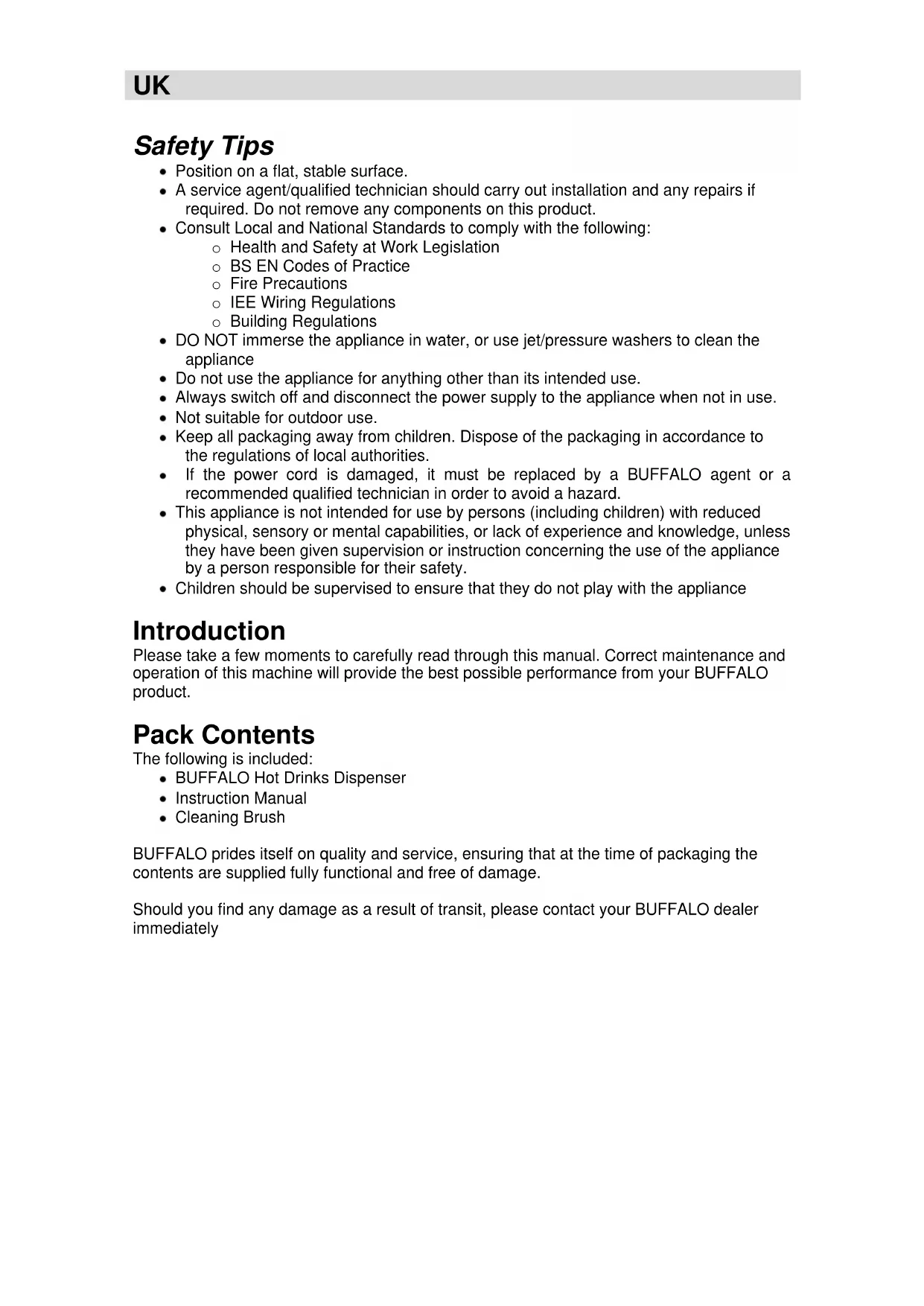
Hot Drinks Dispenser Instruction Manual
Model . Modèle . Modell . Modello . Modelo . Malli GF539
Safety Tips
- Position on a flat, stable surface.
- A service agent/qualified technician should carry out installation and any repairs if required. Do not remove any components on this product.
- Consult Local and National Standards to comply with the following:
o Health and Safety at Work Legislation - BS EN Codes of Practice
- Fire Precautions
- IEE Wiring Regulations
○ Building Regulations
- DO NOT immerse the appliance in water, or use jet/pressure washers to clean the appliance
- Do not use the appliance for anything other than its intended use.
• Always switch off and disconnect the power supply to the appliance when not in use.
- Not suitable for outdoor use.
- Keep all packaging away from children. Dispose of the packaging in accordance to the regulations of local authorities.
- If the power cord is damaged, it must be replaced by a BUFFALO agent or a recommended qualified technician in order to avoid a hazard.
- This appliance is not intended for use by persons (including children) with reduced physical, sensory or mental capabilities, or lack of experience and knowledge, unless they have been given supervision or instruction concerning the use of the appliance by a person responsible for their safety.
- Children should be supervised to ensure that they do not play with the appliance
Introduction
Please take a few moments to carefully read through this manual. Correct maintenance and operation of this machine will provide the best possible performance from your BUFFALO product.
Pack Contents
The following is included:
• BUFFALO Hot Drinks Dispenser
- Instruction Manual
- Cleaning Brush
BUFFALO prides itself on quality and service, ensuring that at the time of packaging the contents are supplied fully functional and free of damage.
Should you find any damage as a result of transit, please contact your BUFFALO dealer immediately
Telephone Helpline: 0845 146 2887 (United Kingdom)
Operation
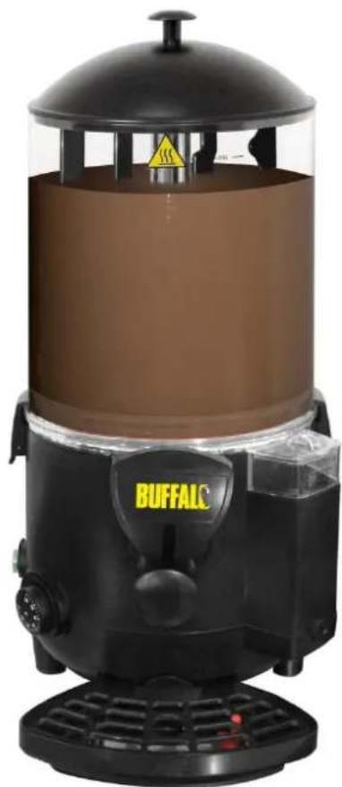
Filling the water boiler tank
• Make sure the power switch is set to OFF.
- Remove the lid to the water boiler tank (Fig 1)
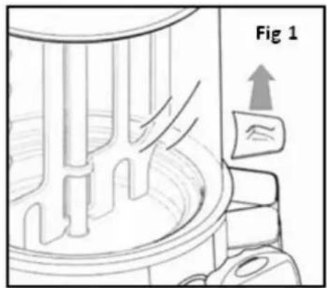
- Fill the tank with water until it reaches the MAX fill line (Fig 2).
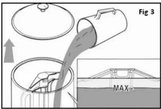
Filling the Bowl
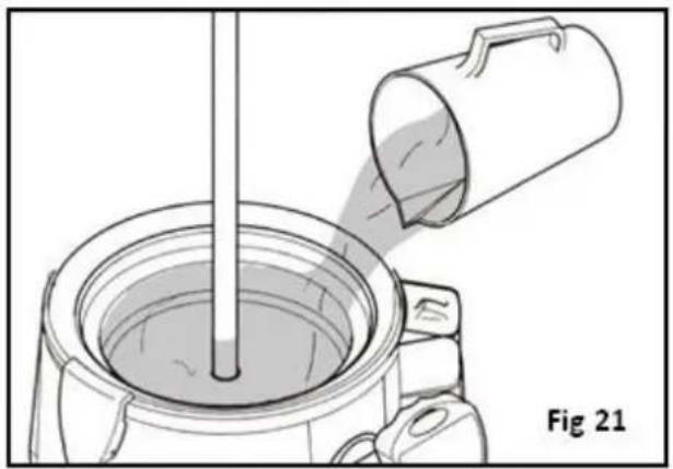
- Remove the lid and pour the beverage prepared according to the manufacturer's instructions into the bowl (Fig 3)
- Never exceed the MAX level mark
- Replace lid
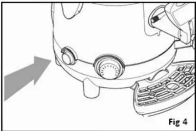
UK
- Turn on the power using the green switch (Fig 4). Switch will illuminate when machine is on.
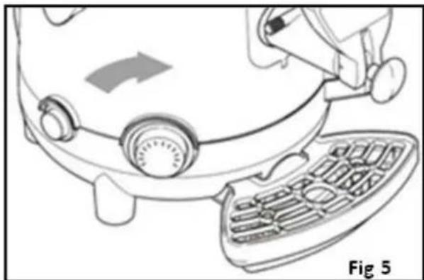
- Set the thermostat to the required temperature (Fig 5).
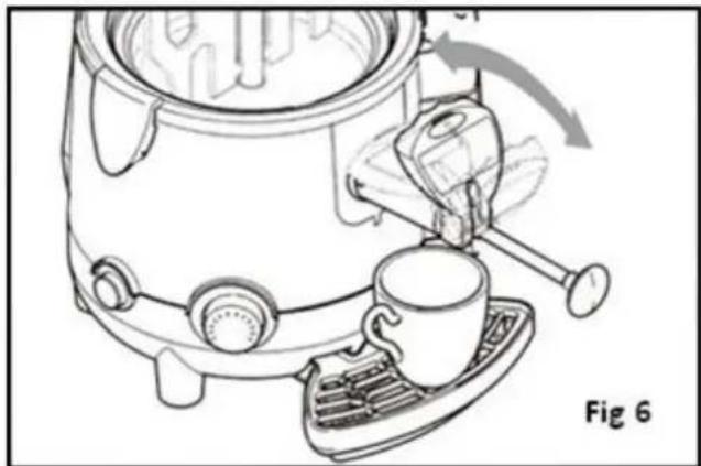
Dispensing the product
Warning: The products dispensed from the machine can be hot please take care to avoid risk of scalding
- Place a suitable cup beneath the tap
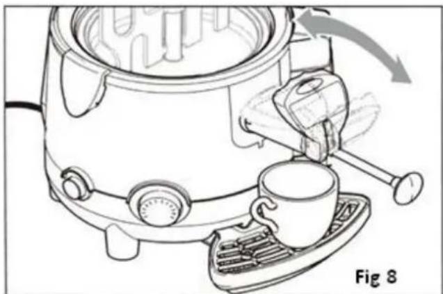
- Push or pull the lever on the tap until the required amount of product has been poured into the cup (Fig 6)
- Release the tap lever so that the product stops pouring.
Telephone Helpline: 0845 146 2887 (United Kingdom)
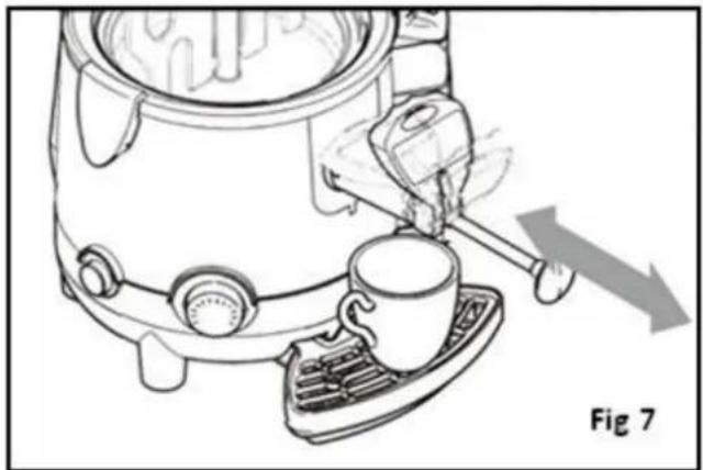
- If the product to be dispensed is especially thick pull the tap Rod out to the maximum position (Fig 7)
- Any clogging in the dispensing line may be removed by sliding the tap rod back and forth (Fig 7)
Warning: never touch the bowl or lid while the machine is operating, since they are very hot; always use the handle when moving the bowl lid
Cleaning and Maintenance
Emptying the bowl
Before cleaning out the bowl, it is first necessary to empty out any product inside it.
- With the machine switched on, empty out all of the product still inside the bowl, using the lever on the tap.
Warning: the product dispensed from the machine has a very high temperature; risk of scalding.
Removing and cleaning the bowl
Warning: before removing the bowl, make sure that the main switch is off, the unit is unplugged from the mains and that the bowl is empty and sufficiently cooled down
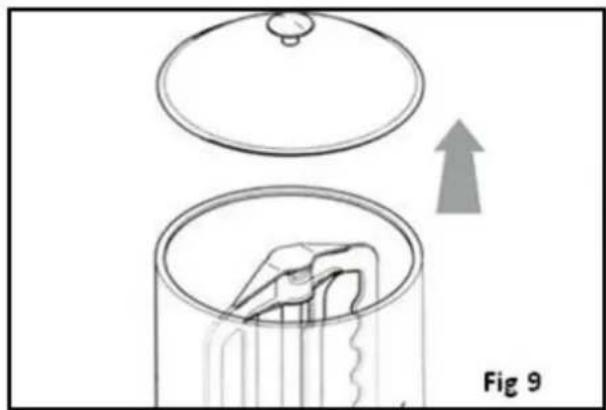
- Remove the lid (Fig 9)
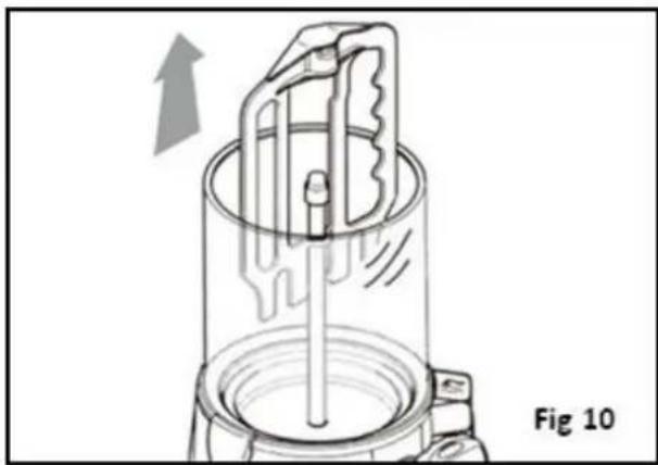
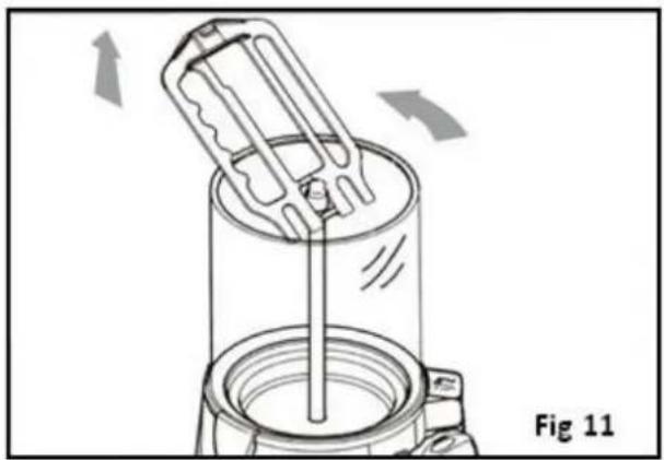
- Slide the mixing paddle upwards to remove it, keeping it in line with the central rod until the bottom slot of the mixing paddle is level with the rotation pin (Fig 10).
- Tilt the mixing paddle and slide it upwards, as illustrated in Fig 11, to remove it completely
Telephone Helpline: 0845 146 2887 (United Kingdom)
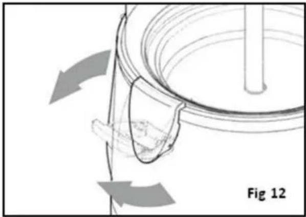
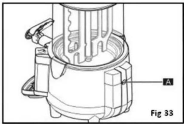
- Unlock the bowl clips as illustrated in Fig 12, to free the bowl from the machine body;
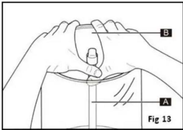
- Release the bowl from the machine body, using two fingers to prise it away from the fixed steel part of the mixer rod (A) and the others to grip the outlet edge of the bowl(B) (Fig 13)
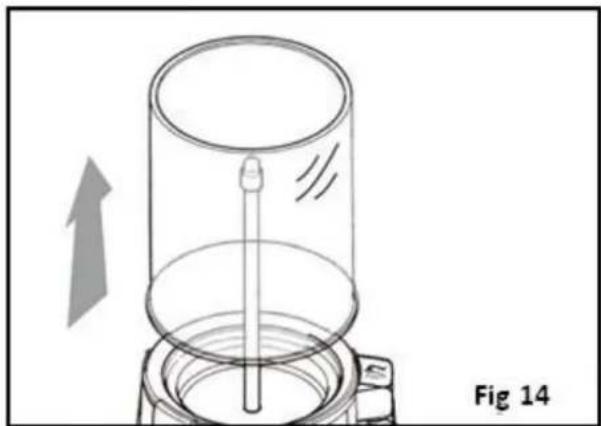
- Gradually pull the bowl harder until it comes away from its seating;
- Slide the bowl upwards using both hands (Fig 14)
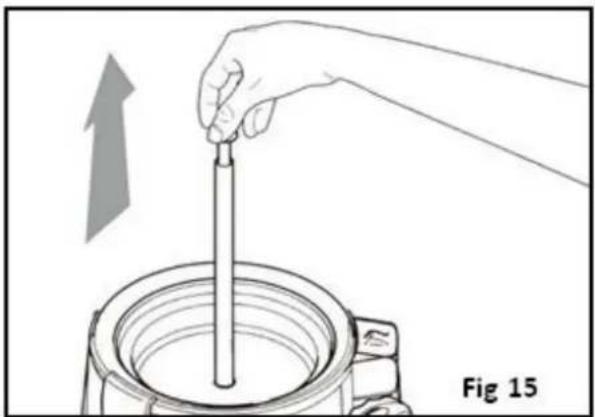
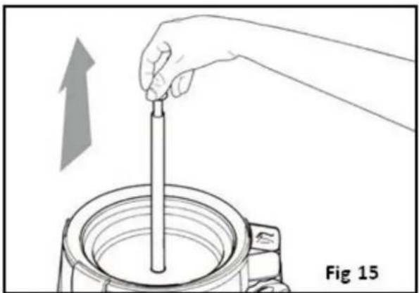
- Slide the mixing rod upwards with one hand, taking care to grip it by the rotation pin (Fig 15)
UK
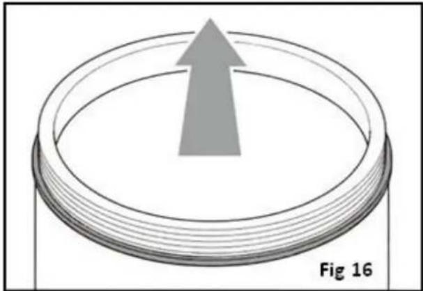
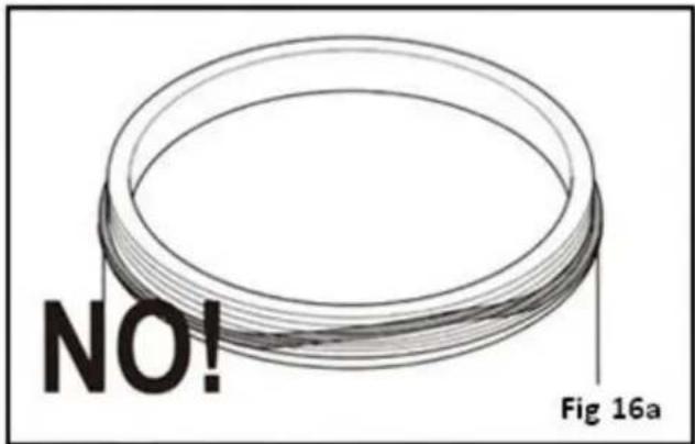
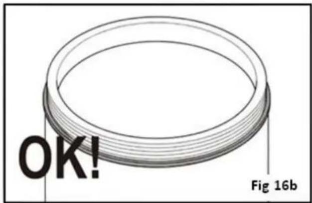
- Place the bowl on a flat surface and using both hands, remove the gasket by sliding it upwards in the direction shown by the arrow (Fig 16)
Wash the disassembled bowl and components with a sanitising detergent solution, rinsing thoroughly with clean hot water.
Before reassembling the bowl ensure the gasket seal is positioned correctly
Moisten the gasket seal with water and fit the bowl back into place. DO NOT USE LUBRICANT.
Warning: make sure that the bowl is correctly fitted to the machine; an incorrectly fitted bowl will cause the product to leak out with risk of scalding!
Reassemble the bowl, rod and mixing paddle by reversing the disassembly instructions
Telephone Helpline: 0845 146 2887 (United Kingdom)
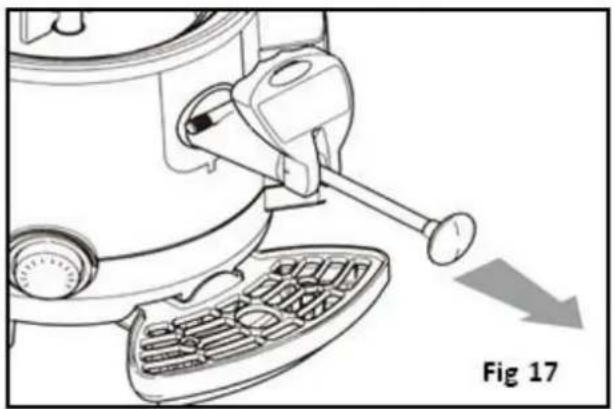
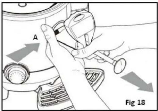
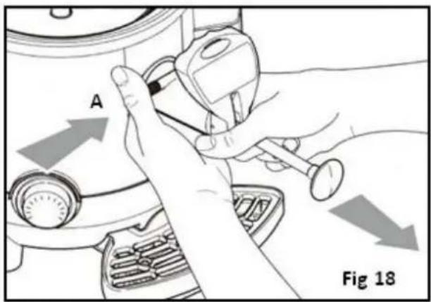
Removing the tap
- Ensure the bowl is empty
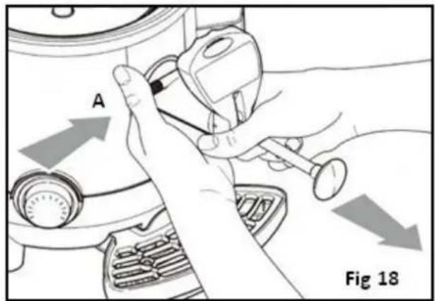
- Move the tap rod to the maximum dispensing position (Fig 17)
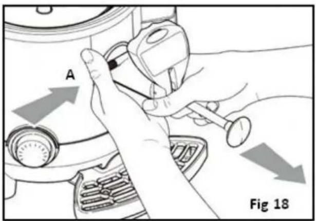
- Press the button(A) securing the tap to the machine and then remove the tap with both hands (Fig 18)
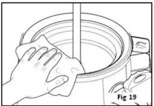
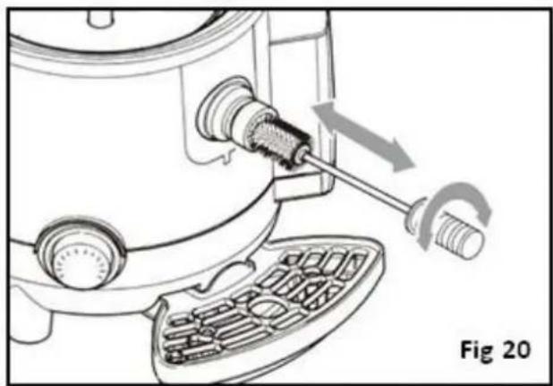
Cleaning the Water Pan
- With bowl and tap removed clean the surface of the pan using a damp cloth and/or a non-abrasive sponge (Fig 19)
UK
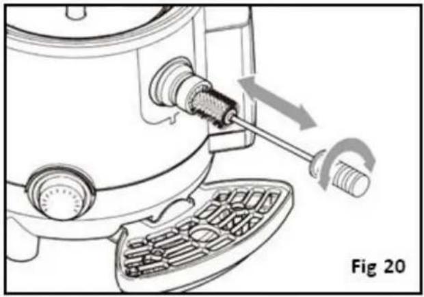
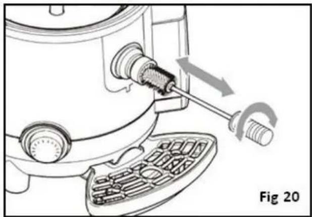
- Clean the channel connecting the bowl and the tap, using a cleaning brush (included) (fig 20)
- Refit the tap;
• Pour a little water inside the pan; - Use the tap to drain out all water from the pan so as to eliminate any small product residues inside the dispensing channel.
Disassembling and cleaning the tap
To clean the inside of the tap, disassemble it as follows:
- Remove the tap (See removing the tap)
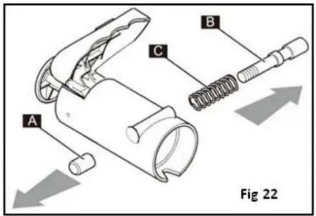
- Place the tap on a clean, flat surface
- Loosen and remove the screw (A)
- Slide out the pin (B) and spring(C) from the seating.
Telephone Helpline: 0845 146 2887 (United kingdom)
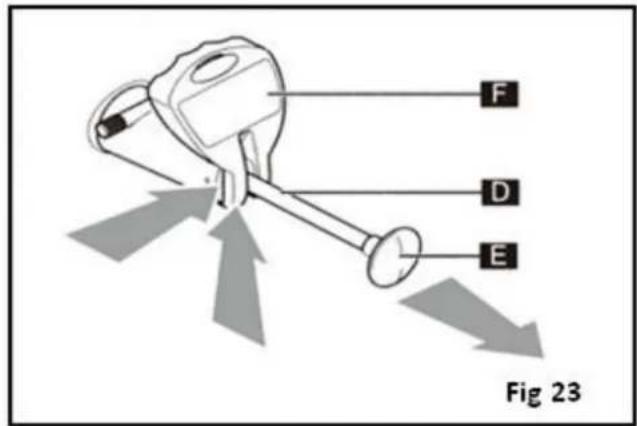
- Pull the lever (D) all the way out from the knob(E) then push the lever(F) upwards from bottom until it comes out from the pin guide (Fig 23). Unscrew the knob E by turning anti-clockwise while holding the rod in place.
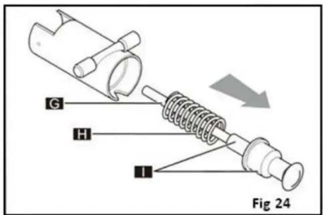
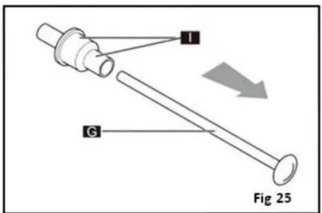
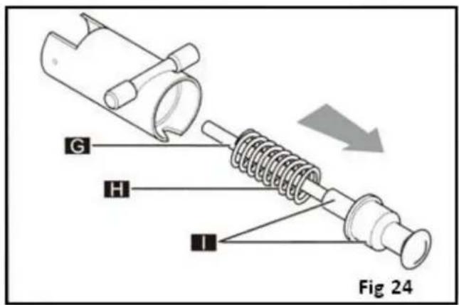
- Pull out the rod (G) and spring (H) from the tap body (the pin/gasket assembly (I) will slide out together with the rod) (Fig 24)
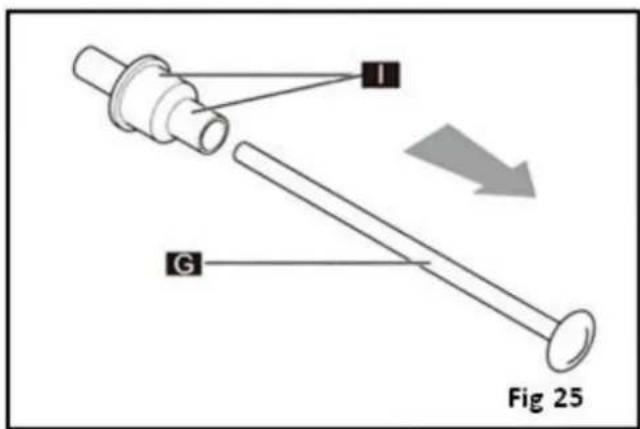
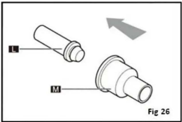
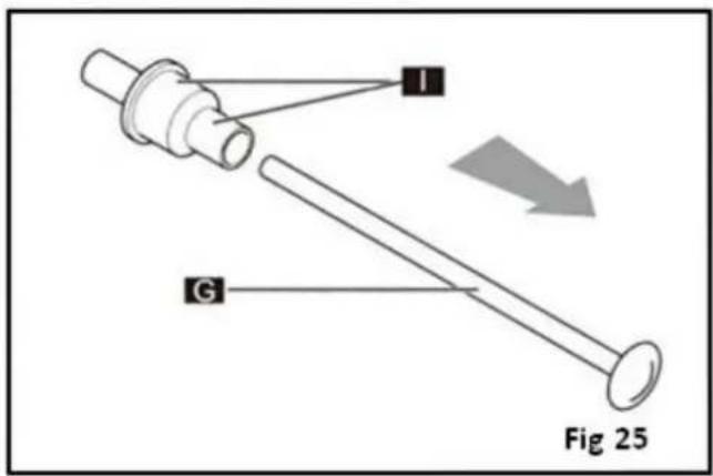
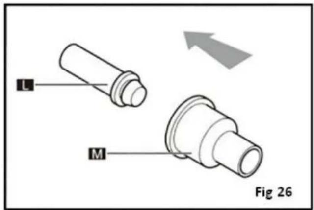
- Detach the rod (G) from the pin/gasket assembly (I) (Fig 25)
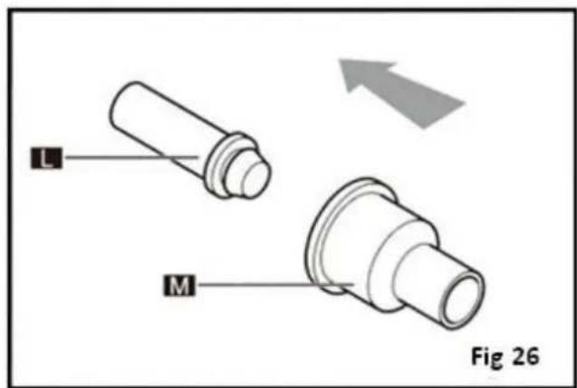
- Disassemble (by pulling) the pin (L) from the gasket (M) (Fig 26)
UK
Wash the disassembled components with a sanitising detergent solution, rinsing thoroughly with clean hot water.
Reassemble the tap by reversing the disassembly instructions.
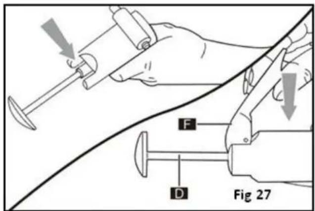
- To fit the lever(F) push the rod (D) from the inside until the guides protrude; the insert the lever(F) and slowly release the rod(D) (Fig 27)
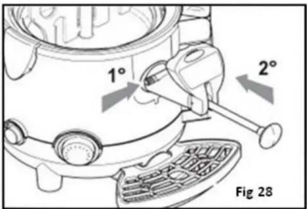
- To fit the tap correctly back in place hold down the button, making sure that the rod is completely extracted
- Introduce the tap into the seat and push until the push button returns to its initial position (Fig 28)
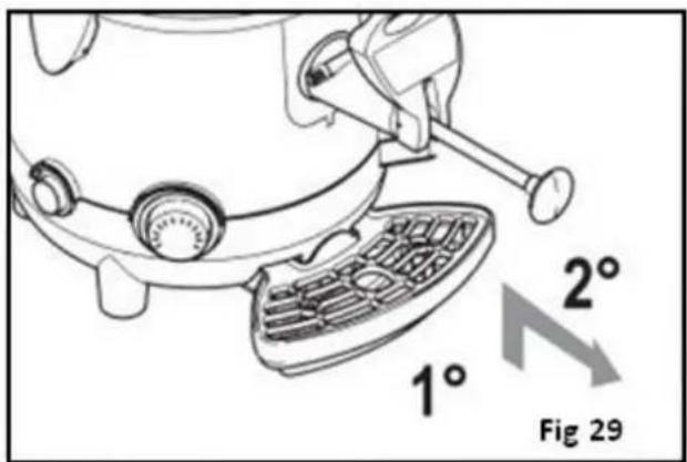
Cleaning the Drip Tray
The drip tray should be emptied and cleaned daily.
Note: the tray needs to be emptied out and cleaned every time that the red float fitted to the grid rises, this is to stop liquid from leaking out.
- Lift the tray with grid and pull it outwards to remove it from its seating.
- Wash the tray and grid separately with warm, soapy water
- Dry all of the components and reposition the grid on top of the tray
- Fit the tray back in place and press down to secure it to the machine.
Telephone Helpline: 0845 146 2887 (United kingdom)
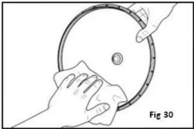
Cleaning the lid
- Remove the bowl lid from the machine
- Clean the surface using a damp cloth and / or a non-abrasive sponge soaked in sanitising product
- Rinse thoroughly using clean water.
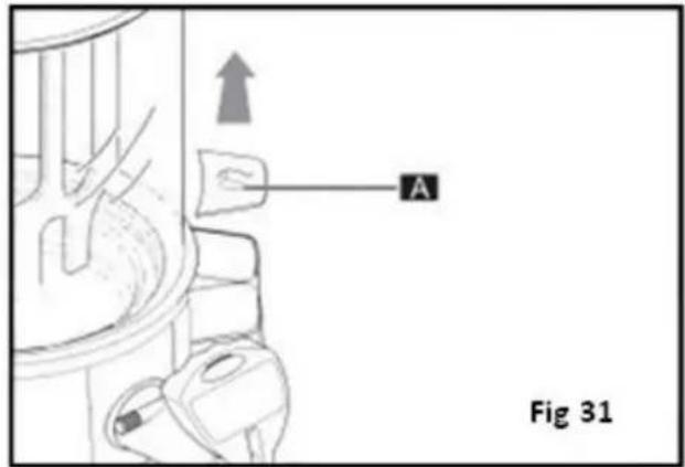
Emptying the boiler Tank
Warning: While the boiler is being emptied, the machine must be unplugged. The boiler may be emptied only when the bowl is empty and the machine has cooled down sufficiently.
- Remove the drip tray
- Remove the cap (A) (Fig 31)
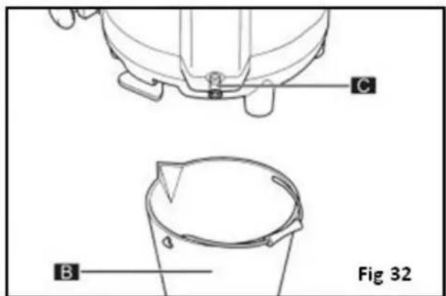
- Place the machine on a flat surface
- Place a container (B) with a capacity of more than 3 litres underneath the bleeder cap (C)
- Use a coin or Allen wrench to unscrew the bleeder cap (C)
- Pull out the cap (C) with a firm movement and wait for all the water to empty out from the boiler tank (Fig 32)
Cleaning and de-scaling the Boiler Tank
Warning: The boiler tank needs to be de-scaled on a regular basis
- Follow the steps for draining out the boiler tank
- Insert and secure the boiler tank bleeder cap
- Fill the boiler tank with a solution of scale remover (suitable for use in coffee machines) and water (following instructions supplied with the scale remover)
- Leave the solution in the tank for the time indicated in the scale remover instructions
• Empty out the solution from inside the boiler tank - Rinse out the tank as per scale remover instructions
Thermal Protector Switch
If the Boiler tank boils dry the units thermal protector switch will activate to protect the heating element. Allow to cool then reset as follows
- Use a suitable tool to loosen and remove the protective screw (A)
- Use a suitable tool to press the button inside to restore normal machine operation.
Telephone Helpline: 0845 146 2887 (United kingdom)
Trouble Shooting
| Fault | Probable Cause | Action |
| Does not heat | No power | Make sure the machine is plugged in correctly |
| Switch set to OFF | Set the switch to ON | |
| Thermal Protector Switch has activated | Reset Thermal Protector Switch | |
| Thermostat set to low | Adjust the thermostat | |
| Mixing paddle does not turn | No power | Make sure the machine is plugged in correctly |
| Mixing rod not fitted correctly | Ensure mixing rod is correctly fitted | |
| Motor Fault | Call Buffalo agent or qualified technician | |
| Switch set to OFF | Set the switch to ON | |
| Tap leaks | Tap not fitted correctly | Empty machine and fit tap as per instructions |
| Build up of debris | Empty machine and clean tap as per instructions | |
| Sealing Gasket needs replacing | Call Buffalo agent or qualified technician | |
| Water escaping from boiler | Temperature too high | Adjust the thermostat |
| Tank filled above MAX indication line | Allow machine to cool then empty the tank and refill to correct level | |
| Sealing gasket needs replacing | Call Buffalo agent or qualified technician | |
| Fault | Probable Cause | Action |
| Product leaks from bottom of bowl | The bowl is not fitted correctly | Empty machine and re-fit bowl as per instructions |
| Sealing gasket needs replacing | Call Buffalo agent or qualified technician | |
| Machine shuts down while in use | The water level in the boiler tank has fallen below the minimum level | Fill the boiler tank to max fill level and reset Thermal Protector Switch |
| No water in boiler tank | Fill the boiler tank to max fill level and reset Thermal Protector Switch | |
| If the machine malfunctions due to causes other than those listed or the proposed corrective actions do not solve the problem please call a Polar agent or qualified technician | ||
Technical Specification
| Model | Voltage | Power | Current | Capacity (Litres) | Dimensions h x w x d mm | Weight (kg) |
| GF539 | 230v 50hz | 1Kw | 4.6A | 9 | 580 x 410 x 280 | 7.5 |
Electrical Wiring
This appliance is supplied with a 3 pin, moulded, BS1363 plug and lead, with a 13 amp fuse as standard.
The plug is to be connected to a suitable mains socket.
This appliance is wired as follows:
• Live wire (coloured brown) to terminal marked L
• Neutral wire (coloured blue) to terminal marked N
- Earth wire (coloured green/yellow) to terminal marked E
This appliance must be earthed, using a dedicated earthing circuit.
If in doubt consult a qualified electrician.
Electrical isolation points must be kept clear of any obstructions. In the event of any emergency disconnection being required they must be readily accessible.
Compliance
The WEEE logo on this product or its documentation indicates that the product must not be disposed of as household waste. To help prevent possible harm to human health and/or the environment, the product must be disposed of in an approved and environmentally safe recycling process. For further information on how to dispose of this product correctly, contact the product supplier, or the local authority responsible for waste disposal in your area. BUFFALO parts have undergone strict product testing in order to comply with regulatory standards and specifications set by international, independent, and federal authorities. BUFFALO products have been approved to carry the following symbol:

All rights reserved. No part of these instructions may be produced or transmitted in any form or by any means, electronic, mechanical, photocopying, recording or otherwise, without the prior written permission of BUFFALO.
Every effort is made to ensure all details are correct at the time of going to press, however, BUFFALO reserve the right to change specifications without notice
Veiligheidstips
NL
NL

De waterpan reinigen
De tap demonteren en reinigen
Behälter füllen
DE
Getränk ausgießen
DE
DE
DE
Boilertank entleeren
Technical Specification
Remplissage du bol
FR
Dépannage
Riempire la vasca.
IT
IT
IT
IT
IT
IT
IT
Llenado del recipiente
ES
ES
ES
ES
Encher a taça
PT
Dispensar o produto
PT
PT
PT
PT
- Destaque a haste (G) do conjunto pino/vedante (I) (Figura 25)
- Desmonte (puxando) o pino (L) do vedante (M) (Figura 26)
PT
PT
DECLARATION OF CONFORMITY
- Conformiteitsverklaring - Déclaration de conformité - Konformitätserklärung - Dichiarazione di conformità - Declaración de conformidad - Declaração de conformidade
Equipment Type • Uitrustingstype • Type d'équipement • Gerätetyp • Tipo di apparecchiatura • Tipo de equipo • Tipo de equipamento
Application of Council Directives(s)
Toepassing van Europese Richtlijn(en) • Application de la/des directive(s) du Conseil • Anwendbare EU-Richtlinie(n) • Applicazione delle Direttive • Aplicación de la(s) directiva(s) del consejo • Aplicação de directiva(s) do Conselho
Standards
Standaarden • Normes • Normen • Standard • Estándares • Normas
Hot Drinks Dispenser
GF539
LVD Directive 2006/95/EC
EMC Directive 2004/108/EC
RoHS Directive 2011/65/EU
Food Contact Directive EC/1935/2004
EN 60335-2-15:2002+A1:2005
+A2:2008, EN60335-1:2002
EN61000-3-3:2008, IEC 62321:2008,
LFGB 30 & 31
Buffalo
Fourth Way,
Avonmouth,
Bristol, BS11 8TB
United Kingdom
I, the undersigned, hereby declare that the equipment specified above conforms to the above Directive(s) and Standard(s).
- HOT DRINKS DISPENSER INSTRUCTION MANUAL
- SAFETY TIPS
- INTRODUCTION
- PACK CONTENTS
- TELEPHONE HELPLINE: 0845 146 2887 (UNITED KINGDOM)
- OPERATION
- FILLING THE WATER BOILER TANK
- FILLING THE BOWL
- UK
- DISPENSING THE PRODUCT
- CLEANING AND MAINTENANCE
- EMPTYING THE BOWL
- REMOVING AND CLEANING THE BOWL
- REMOVING THE TAP
- CLEANING THE WATER PAN
- DISASSEMBLING AND CLEANING THE TAP
- CLEANING THE DRIP TRAY
- CLEANING THE LID
- EMPTYING THE BOILER TANK
- CLEANING AND DE-SCALING THE BOILER TANK
- THERMAL PROTECTOR SWITCH
- ELECTRICAL WIRING
- COMPLIANCE
- VEILIGHEIDSTIPS
- NL
- DE WATERPAN REINIGEN
- DE TAP DEMONTEREN EN REINIGEN
- BEHÄLTER FÜLLEN
- DE
- GETRÄNK AUSGIESSEN
- BOILERTANK ENTLEEREN
- REMPLISSAGE DU BOL
- FR
- RIEMPIRE LA VASCA
- IT
- LLENADO DEL RECIPIENTE
- ES
- ENCHER A TAÇA
- PT
- DISPENSAR O PRODUTO
- DECLARATION OF CONFORMITY
- APPLICATION OF COUNCIL DIRECTIVES(S)
- STANDARDS
Brand : BUFFALO
Model : GF539
Category : Water dispenser