
1046 - Processor DBX - Free user manual and instructions
Find the device manual for free 1046 DBX in PDF.

| Product Type | Professional quad compressor/limiter |
| Brand | DBX |
| Model | 1046 |
| Category | Audio processor |
| Rack Format | 1U (19 inches) |
| Dimensions (W x H x D) | 482.6 x 44.45 x 203 mm (approx.) |
| Weight | 4.5 kg (approx.) |
| Power Supply | Mains 100-240 V AC, 50/60 Hz, 16 W |
| Power Consumption | 16 W |
| Operating Levels | +4 dBu or -10 dBV (selectable per channel) |
| Audio Inputs | XLR female and 6.35 mm stereo jack (balanced or unbalanced) |
| Audio Outputs | XLR male and 6.35 mm stereo jack (balanced or unbalanced) |
| Number of Channels | 4 channels (configurable as 2 stereo or 4 mono) |
| Main Functions | Compression with OverEasy®, PeakStopPlus™ limiting, stereo coupling, bypass, input/output display and gain reduction |
| Threshold Range (THRESHOLD) | 60 dB |
| Compression Ratio (RATIO) | 1:1 to ∞:1 |
| Output Gain (OUTPUT GAIN) | -20 dB to +20 dB |
| PeakStopPlus™ Level | +4 dBu to +22 dBu (or off) |
| Visual Indicators | LED gain reduction (0-30 dB), 8-LED input/output display, PeakStopPlus LED, OverEasy LED, Bypass LED, Stereo Couple LED |
| Operating Ambient Temperature | Up to 45°C |
| Fuse | 2 fuses (one active, one spare) same type and rating |
| Maintenance and Cleaning | Do not open, do not expose to water, unplug during storms, clean with a dry cloth |
| Safety | Earthing mandatory, respect mains cord polarity, do not use near water |
| Spare Parts and Repairability | Fuse accessible externally, repair by qualified technician only |
| General Information | Manual available in French, German, English, Spanish and other languages upon request. Manufacturer's warranty void if unauthorized opening. |
Frequently Asked Questions - 1046 DBX
User questions about 1046 DBX
0 question about this device. Answer the ones you know or ask your own.
Ask a new question about this device
Download the instructions for your Processor in PDF format for free! Find your manual 1046 - DBX and take your electronic device back in hand. On this page are published all the documents necessary for the use of your device. 1046 by DBX.
USER MANUAL 1046 DBX
PROFESSIONAL PRODUCTS
H A Harman International Company
OPERATION MANUAL
MODE D'EMPLOI
BEDIENUNGSANLEITUNG
MODO DE EMPLEO
CAUTION
RISK OF ELECTRIC SHOCK DO NOT OPEN

ATTENTION:
RISQUE DE CHOC ELECTRIQUE - NE PAS OUVRIR
WARNING: TO REDUCE THE RISK OF FIRE OR ELECTRIC SHOCK DO NOT EXPOSE THIS EQUIPMENT TO RAIN OR MOISTURE
The symbols shown above are internationally accepted symbols that warn of potential hazards with electrical products. The lightning flash with arrowpoint in an equilateral triangle means that there are dangerous voltages present within the unit. The exclamation point in an equilateral triangle indicates that it is necessary for the user to refer to the owner's manual.
These symbols warn that there are no user serviceable parts inside the unit. Do not open the unit. Do not attempt to service the unit yourself. Refer all servicing to qualified personnel. Opening the chassis for any reason will void the manufacturer's warranty. Do not get the unit wet. If liquid is spilled on the unit, shut it off immediately and take it to a dealer for service. Disconnect the unit during storms to prevent damage.
U.K. MAINS PLUG WARNING
A moulded mains plug that has been cut off from the cord is unsafe. Discard the mains plug at a suitable disposal facility. NEVER UNDER ANY CIRCUM-STANCES SHOULD YOU INSERT A DAMAGED OR CUT MAINS PLUG INTO A 13 AMP POWER SOCKET. Do not use the mains plug without the fuse cover in place. Replacement fuse covers can be obtained from your local retailer. Replacement fuses are 13 amps and MUST be ASTA approved to BS1362.
SAFETY INSTRUCTIONS
NOTICE FOR CUSTOMERS IF YOUR UNIT IS EQUIPPED WITH A POWER CORD.
WARNING: THIS APPLIANCE MUST BE EARTHED.
The cores in the mains lead are coloured in accordance with the following code:
GREEN and YELLOW - Earth
BLUE - Neutral
BROWN - Live
As colours of the cores in the mains lead of this appliance may not correspond with the coloured markings identifying the terminals in your plug, proceed as follows:
- The core which is coloured green and yellow must be connected to the terminal in the plug marked with the letter E, or with the earth symbol, or coloured green, or green and yellow.
- The core which is coloured blue must be connected to the terminal marked N or coloured black.
- The core which is coloured brown must be connected to the terminal marked L or coloured red.
This equipment may require the use of a different line cord, attachment plug, or both, depending on the available power source at installation. If the attachment plug needs to be changed, refer servicing to qualified service personnel who should refer to the table below. The green/yellow wire shall be connected directly to the unit's chassis.
| CONDUCTOR | WIRE COLOR | ||
| Normal Alt | |||
| L | LIVE | BROWN | BLACK |
| N | NEUTRAL | BLUE | WHITE |
| E | EARTH GND | GREEN/YEL | GREEN |
WARNING: If the ground is defeated, certain fault conditions in the unit or in the system to which it is connected can result in full line voltage between chassis and earth ground. Severe injury or death can then result if the chassis and earth ground are touched simultaneously.
WARNING
FOR YOUR PROTECTION, PLEASE READ THE FOLLOWING:
WATER AND MOISTURE: Appliance should not be used near water (e.g. near a bathtub, washbowl, kitchen sink, laundry tub, in a wet basement, or near a swimming pool, etc). Care should be taken so that objects do not fall and liquids are not spilled into the enclosure through openings.
POWER SOURCES: The appliance should be connected to a power supply only of the type described in the operating instructions or as marked on the appliance.
GROUNDING OR POLARIZATION: Precautions should be taken so that the grounding or polarization means of an appliance is not defeated.
POWER CORD PROTECTION: Power supply cords should be routed so that they are not likely to be walked on or pinched by items placed upon or against them, paying particular attention to cords at plugs, convenience receptacles, and the point where they exit from the appliance.
SERVICING: To reduce the risk of fire or electric shock, the user should not attempt to service the appliance beyond that described in the operating instructions. All other servicing should be referred to qualified service personnel.
FOR UNITS EQUIPPED WITH EXTERNALLY ACCESSIBLE FUSE RECEPTACLE: Replace fuse with same type and rating only.
ELECTROMAGNETIC COMPATIBILITY
This unit conforms to the Product Specifications noted on the Declaration of Conformity. Operation is subject to the following two conditions:
- this device may not cause harmful interference, and
- this device must accept any interference received, including interference that may cause undesired operation.
Operation of this unit within significant electromagnetic fields should be avoided.
- use only shielded interconnecting cables.
DECLARATION OF CONFORMITY
Manufacturer's Name: dbx Professional Products
Manufacturer's Address: 8760 S. Sandy Parkway Sandy, Utah 84070, USA
declares that the product
dbx 1046
conforms to the following Product Specifications:
Safety: EN 60065 (1993)
IEC 65 (1985) with
Amendments 1, 2, 3
EMC: EN 55013 (1990)
EN 55020 (1991)
Supplementary Information:
The products herewith comply with the requirements of the EMC Directive 89/336/EEC (1989), as amended by the CE marking directive 93/68/EEC (1993).
dbx Professional Products
President
8760 S. Sandy Parkway
Sandy, Utah 84070, USA
April 22, 1996
European Contact: Your local dbx Sales and Service Office or Harman Music Group
8760 South Sandy Parkway Sandy, Utah 84070 USA
Ph: (801) 566-8800 Fax:(801) 568-7583
MANUAL CONTENTS
ENGLISH 2
FRANÇAIS 9
DEUTSCH 19
ESPAÑOL 31
ENGLISH CONTENTS
INTRODUCTION 2
INSPECTION 2
WARRANTY 2
CONNECTING THE 1046 TO YOUR SYSTEM ....3
Congratulations and thank you for your purchase of the dbx 1046 Quad Compressor Limiter. The dbx 1046 is a high performance multifunctional unit designed to deliver all the flexibility and power that a professional user demands. The dbx 1046 incorporates the new advanced dbx V2 ^™ VCA for high system performance. We recommend you take a moment to read through this Operation manual. It provides information that will assist you in system set-up.
Inspection
Verify that the 1046's package contains the following:
•1046 Unit (according to Model number marked on package)
• AC Power Cord
•Operation Manual
•Registration Card
•4 Rack Mount Screws and Washers
If any of these items are missing, contact dbx customer service at (801) 568-7660.
Warranty
- The warranty registration card that accompanies this product must be mailed within 30 days after purchase date to validate this warranty. Proof-of-purchase is considered to be the burden of the consumer.
- dbx warrants this product, when bought and used solely within the U.S., to be free from defects in materials and workmanship under normal use and service.
- dbx liability under this warranty is limited to repairing or, at our discretion, replacing defective materials that show evidence of defect, provided the product is returned to dbx WITH RETURN AUTHORIZATION from the factory, where all parts and labor will be covered up to a period of two years. A Return Authorization number must be obtained from dbx by telephone. The company shall not be liable for any consequential damage as a result of the product's use in any circuit or assembly.
- dbx reserves the right to make changes in design or make additions to or improvements upon this product without incurring any obligation to install the same additions or improvements on products previously manufactured.
- The foregoing is in lieu of all other warranties, expressed or implied, and dbx neither assumes nor authorizes any person to assume on its behalf any obligation or liability in connection with the sale of this product. In no event shall dbx or its dealers be liable for special or consequential damages or from any delay in the performance of this warranty due to causes beyond their control.
2 Introduction
Connecting the 1046 to your system
To connect the 1046 to your system, refer to the following steps:
- Turn off all equipment before making any connections.
- Mount the 1046 in a rack
Install the 1046 in a rack with the rack screws provided. It can be mounted above or below anything that does not generate excessive heat. Ambient temperatures should not exceed 113^ F ( 45^ C) when equipment is in use. Although the unit is shielded against radio frequency and electromagnetic interference, extremely high fields of RF and EMI should be avoided.
- Make audio connections via XLR, 1/4"TRS, or 1/4"TS plugs.
Both types of connectors for the inputs and outputs can be used for balanced or unbalanced connections. The use of more than one connector at a time for the input/output pair could unbalance balanced lines, cause phase cancellations, short a conductor to ground, or cause damage to other equipment connected to the 1046.
- Apply power to the 1046
Connect the AC power cord to the AC power receptacle on the back of the unit. Route the AC power cord to a convenient power outlet away from audio lines. The unit may be turned on and off via the rear panel power switch or from a central equipment power switch.
Operating Controls
Front Panel
Gain Reduction Meter - This 8 stage meter shows the amount of gain reduction due to both
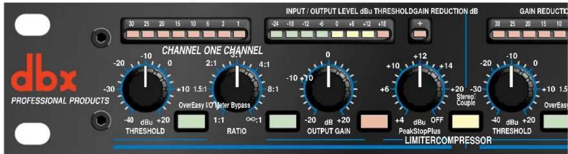
compression and/or Intelligent Predictive Limiting™, displaying gain reduction from 0 to 30 dB.
Compressor Threshold Control - This control sets the level above which compression occurs, and has a 60 dB range.
OverEasy® Switch - OverEasy® provides a smooth transition from the compressor's linear region to
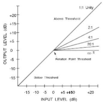
the compressed region. This smooth transition greatly reduces compression artifacts and allows higher compression ratios while still maintaining the natural characteristics of the signal. The switch lights to indicate OverEasy® processing is enabled. When conventional hard knee processing is desired, disable the OverEasy® function. See Figure 1 below.
Figure 1: Hard Knee Compression Curve and OverEasy® Compression Curve.
line
| INPUT LEVEL (dB) | OUTPUT LEVEL (dB) | | ---------------- | ----------------- | | -15 | -15 | | -10 | -10 | | -5 | -5 | | 0 | 0 | | 5 | 5 | | 10 | 10 | | 15 | 15 | | 20 | 20 |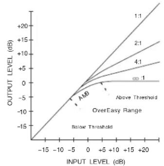
line
| INPUT LEVEL (dB) | OUTPUT LEVEL (dB) | | ---------------- | ----------------- | | -15 | -15 | | -10 | -10 | | -5 | -5 | | 0 | 0 | | 5 | 5 | | 10 | 10 | | 15 | 15 | | 20 | 20 |Compressor Ratio Control - This control selects the ratio between input and the output levels for signals above the level set by the COMPRESSION THRESHOLD control. It is adjustable between 1:1 and :1. Note, when OverEasy® processing is selected, the ratio transitions smoothly from the linear to the compressed region. As the signal exceeds the threshold, the ratio approaches the ratio set by the COMPRESSOR RATIO control.
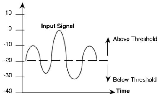
Figure 2 shows the effect of 2:1 compression on a signal as it rises above and falls below the threshold. Below the threshold the signal is not affected. Above the threshold, the output signal increases by only half of the increase (in dB) of the input signal level. In other words, with a 2 dB increase in input level, the output increases by only 1 dB, hence the 2:1 compression ratio.
Signal Level (dBu)
line
| Time | Input Signal | |------|--------------| | -20 | -20 | | -15 | -10 | | -10 | 0 | | -5 | -10 | | 0 | 0 | | 5 | -10 | | 10 | -20 | | 15 | -10 | | 20 | 0 |Signal Level (dBu)
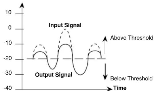
Figure 2: Compression Effect on Signal Level with a 2:1 Ratio at a -20 dBu Threshold
Input/Output Level Meter - This 8-stage meter directly reads the input and output levels when the rear-panel OPERATING LEVEL SWITCH is in the +4 dBu position. In the -10 dBV position, the input signal is boosted by 11.8 dB (the difference between +4 dBu and -10 dBV) to convert a semi-pro -10 dBV level signal to the professional +4 dBu internal level of the 1046, while the output signal is attenuated by 11.8 dB to convert back to a -10 dBV level. Since the meter is calibrated for +4 dBu operation, it reads about 12 dB higher than the actual input and output signal levels when the OPERATING LEVEL SWITCH is set to -10 dBV.
Input/Output Meter Switch - This switch selects the signal for metering by the INPUT/OUTPUT LEVEL
METER. The switch lights indicating the input signal is currently being sent to the meter. When the switch is in the out position, the output signal is selected for metering, and the switch will not be illuminated.
Output Gain Control - This control sets the output gain of the compressor. It can be continuously adjusted between -20 dB and +20 dB. Use this control to compensate for signal level loss due to compression and to adjust the nominal output level of the unit.
Bypass Switch - This switch bypasses the unit completely, "hard-wiring" the input directly to the output, and the signal is not processed in any way. The switch will light indicating that the unit is currently bypassed.
PeakStopPlus™ Level Control - This control sets the level to which the output signal is reduced whenever it exceeds this level. It can be adjusted between +4 dBu and +22 dBu (OFF). This PeakStopPlus™ limiter uses a proprietary dbx two-stage limiting process. The first stage is the Instantaneous Transient Clamp™ which clamps the signal with a soft logarithmic clamp function. This logarithmic function assures that the signal will not exceed the level set by the PeakStopPlus™ LEVEL control by more than 2 dB typically, and that it will not introduce harsh artifacts. The second stage is a unique program limiter featuring Intelligent Predictive Limiting™. Its function is to monitor the input signal and intelligently predict the amount of gain reduction needed to keep the output signal below the ceiling set by the Instantaneous Transient Clamp™. The PeakStopPlus™ limiter must come after the OUTPUT GAIN control. If the OUTPUT GAIN is set too high as compared to the PeakStopPlus™ LEVEL control, continuous limiting can occur. While PeakStopPlus™ is typically used as a protective function, creative effects can be achieved by intentionally driving the signal into heavy PeakStopPlus™ limiting. Great care has gone into the design of the PeakStopPlus™ limiter to keep it acoustically transparent. Appropriate use of it can protect your gear while keeping the signal free of artifacts.
PeakStopPlus™ Threshold (+) LED Indicator - This LED illuminates when the output signal exceeds the level set by the PeakStopPlus™ LEVEL control indicating that PeakStopPlus™ limiting is occurring.
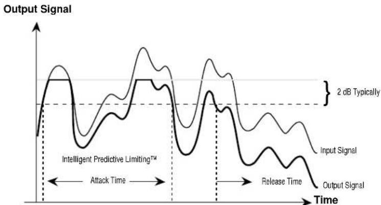
Figure 3 illustrates the protective action of the PeakStopPlus ^™ limiter. The signal with the thin line weight represents an unaltered input signal. As you can see, peaks of the input signal exceed the clamping level. The signal with the heavier line weight represents the output signal. The peaks of the input signal which exceeded the clamping level are not allowed to exceed this level at the output. This instantaneous protective action is invaluable for driver protection in speaker systems and for digital recording where it is desirable to record as “hot” as possible, while still avoiding the disastrous result of running out of headroom. Following this clamping action, Intelligent Predictive Limiting ^™ takes over, typically within 5ms, as long as the input signal continues to exceed the PeakStopPlus ^™ threshold. This program limiter quickly attenuates the input signal to a level safely below the clamping level, typically 2 dB lower than the clamping level. The PeakStopPlus ^™ level control is calibrated to this lower level, so if an absolute ceiling is required, set the level 2 to 3 dB below the front panel setting.
The attack and release times of the Instantaneous Transient Clamp ^™ are zero, while the Intelligent Predictive Limiting ^™ attack and release times are program-dependent. That is, for larger excursions over the threshold, the attack time speeds up, and for smaller excursions over the threshold, the attack time slows down. Similarly, for large excursions over the threshold which cause more PeakStopPlus ^™ gain reduction, the release time increases and is roughly proportional to the amount of gain reduction that occurred.
line
| Time Segment | Input Signal | Output Signal | | ------------------------ | ------------ | ------------- | | Attack Time | ~0.8 | ~0.6 | | Release Time | ~0.7 | ~0.5 | | 2 dB Typically | ~0.9 | ~0.7 |Figure 3: Protective Action of the PeakStopPlus™ Limiter
Stereo Couple Switch - These switches change the 1046 from four independent compressors into two stereo compressors. In stereo mode, Channel 1 is a host with Channel 2 synchronized to it, and Channel 3 is a host with channel 4 synchronized to it. Each of the Channel 2 and 4 controls and switch functions will be overridden and controlled by the Channel 1 and 3 controls and switches, respectively, except for the I/O Meter and Bypass switches. Also, Channel 2's and 4's Compressor Threshold, and PeakStopPlus™ Threshold meters will be disabled, while these synchronized channels' Gain Reduction meters will indicate the amount of gain reduction occurring, as on their masters' Gain Reduction Meters. All 4 channels have equal precedence as far as signal processing is concerned. The dbx 1046 uses True RMS Power Summing™, an extremely accurate and musical way to combine detector outputs in a stereo situation. The switch will light to indicate that the 1046 is in the Stereo Couple mode.
Rear Panel Operations
Rear Panel
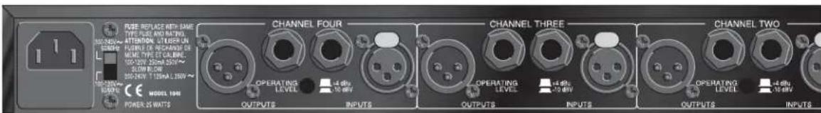
AC Power Receptacle - Use the supplied AC cable to connect the unit to AC power. The AC receptacle includes an integral pull-out fuse drawer which contains two fuses; the active fuse and a spare fuse. Replace the fuse with the same type and rating only.as indicated on the rear panel.
Audio Inputs - Each channel features both XLR and 1/4" TRS electronically balanced inputs. Inputs may be used in a balanced or unbalanced configuration. Note that the XLR and 1/4' inputs may NOT be used simultaneously.
Audio Outputs - Each channel features both XLR and 1/4" TRS servo-balanced outputs. Outputs may be used in a balanced or unbalanced configuration. Unlike the inputs both the XLR and the 1/4" outputs may be used simultaneously.
Operating Level Switch - This switch selects between a -10 dBV and +4 dBu nominal operating level. When the switch is in the in position, a -10 dBV operating level is selected. When it is in the out position, +4 dBu is selected. This switch affects both the input and the output levels.
Applications
Fattening Kick Drums and Compressing Other Drums
Weak, flabby kick drums often have too much boom, and not enough slap. To tighten them up, start with the 1046 adjusted for a medium to high RATIO (e.g., 6:1), adjust the THRESHOLD control so that the GAIN REDUCTION meters show 15 dB of gain reduction, then increase the RATIO if necessary. In OverEasy® mode, the 1046 takes slightly longer to react than in Hard Knee mode, and will therefore emphasize the slap at the beginning of the note and reduce the boominess of its body. The 1046 also works well for tightening snare drums and tom toms and can be used with drum machines to effectively alter the character of any electronic drum sound.
Raising a Signal Out of a Mix
Since reducing dynamic range increases the average signal level by a small amount, a single track can be raised out of a mix by boosting its level slightly and applying compression. Start with a 2:1 RATIO and a relatively low THRESHOLD setting (-20 dBu). Adjust both controls as necessary.
Compressors have also been used to bring vocals to the forefront of a mix in volume-restricted studios (e.g. home studios). Start by adding a foam windscreen to the mic (if it doesn't have one). Set the RATIO to 10:1 and the THRESHOLD to -10 dBu. With your mouth approximately 2 inches from the mic, sing the vocal part, but with less volume than normal. Use phrasing to give the part some intensity. An equalizer (e.g., a dbx 242 Parametric Equalizer, dbx 30 Series Graphic Equalizers) or a vocal effects device (e.g., a dbx 290 digital reverb) can be added to further define the performance.
Note: When compressing a stereo program with a 1046, the factors affecting a compression curve and the actual RATIO and THRESHOLD settings are the same as those previously covered with reference to single channels of program material. However, it will generally be found that large amounts of compression are more audible in a mixed stereo program than they might be on the separate tracks that were mixed to create the program.
Smoothing out Microphone Levels
When distance is created between the vocalist and the microphone there will be a variation in the signal level. Start with low compression (around 2:1) to smooth out any variations. Limiting also benefits intelligibility by allowing low-level input signals to be reproduced through the system at higher volume.
Smoothing out Musical Instrument Levels
Compression smooths out the variations of loudness among instruments. Using the 1046 can also increase the instrument's sustain. Compress the instrument's output with a ratio of about 4:1.
Speaker Protection
Compressors are frequently used to prevent excessive program levels from distorting power amps and/or damaging drivers in a sound-reinforcement system (whether you're doing auditorium, church, or
Applications
club sound engineering, or are a mobile DJ, or like to push the limits of your home's audio entertainment center). Set the 1046 for limiting (Hard Knee mode On, with a RATIO of 10:1 or greater) and adjust the THRESHOLD to provide 15 dB or more of compression (just a few dB below the input clip). For low-level signals, the 1046 won't change gain, but if large signals come along, the gain will be reduced to prevent clipping and save sensitive system components from excessive heat buildup or other types of damage.
Note: PeakStopPlus™ Limiting can also be used to prevent speaker damage.
Preventing Digital Recording Overload
Some digital recorders and samplers produce audible distortion when they exceed their maximum operating level. The 1046 can be used to ensure that audio input does not overload a digital recorder's A/D (analog-to-digital) converters. The 1046 can perform this function quietly enough for all digital media. To use the 1046 so that no changes in gain occur unless an emergency arises (wildly excessive levels), set Hard Knee mode On, the RATIO to :1 , and the THRESHOLD highest level before digital overload.
Note: PeakStopPlus ^™ limiting can also be used to prevent raucous-sounding digital overload.
Installation Considerations
Hookups and Cabling: The 1046 is designed for nominal -10 dBV or +4 dBu levels. The 1046 can be used with either balanced or unbalanced sources and the outputs can be used with either balanced or unbalanced loads, provided the proper cabling is used.
Normal Balanced Connections for Inputs and Outputs
Connection XLR TRS 1/4" Jack
Ground: Pin 1 Sleeve
High: Pin 2 Tip
Low: Pin 3 Ring
Normal Unbalanced Connections for Inputs and Outputs
Connection XLR TRS 1/4" Jack TS 1/4" Jack
Ground: Pin 1 Sleeve Sleeve
High: Pin 2 Tip Tip
Low (ground): Pin 3 Ring Sleeve
Tie pin 3 to the ground for unity gain in/out of the 1046 when using unbalanced input connections to balanced output connections or balanced input connections to unbalanced output connections. To do otherwise won't hurt the unit but will result in unmatched input to output levels, and the level control will not be properly calibrated.
FRANÇAIS
ATTENTION:
CAUTION
RISK OF ELECTRIC SHOCK DO NOT OPEN

RISQUE DE CHOC ELECTRIQUE - NE PAS OUVRIR
WARNING: TO REDUCE THE RISK OF FIRE OR ELECTRIC SHOCK DO NOT EXPOSE THIS EQUIPMENT TO RAIN OR MOISTURE
dbx Professional Products
Adresse fabricant :
8760 S. Sandy Parkway
Sandy, Utah 84070, USA
dbx Professional Products
President of dbx
8760 S. Sandy Parkway
Sandy, Utah 84070, USA
22 Avril 1996
TABLE DES MATIÈRES
INTRODUCTION ......12
VÉRIFICATION....12
CONNEXIONS....12
COMMANDES....13
APPLICATIONS 17
INSTALLATION....18
CARACTÉRISTIQUES TECHNIQUES ....42
Introduction
WARNING: TO REDUCE THE RISK OF FIRE OR ELECTRIC SHOCK DO NOT EXPOSE THIS EQUIPMENT TO RAIN OR MOISTURE
dbx Professional Products
President
8760 S. Sandy Parkway
Sandy, Utah 84070, USA
- April 1996
Inhalt
EINLEITUNG 22
KONTROLLE 22
GARANTIEBEDINGUNGEN....22
ANSCHLIESSEN DES DBX 1046 AN IHRE ANLAGE....23
BEDIENELEMENTE 23
RÜCKSEITE 27
ANWENDUNGEN 27
WARNING: TO REDUCE THE RISK OF FIRE OR ELECTRIC SHOCK DO NOT EXPOSE THIS EQUIPMENT TO RAIN OR MOISTURE
dbx Professional Products
Vice President of Engineering
8760 S. Sandy Parkway
Sandy, Utah 84070, USA
22 de abril 1996
8760 South Sandy Parkway Sandy, Utah 84070 USA
Ph: (801) 566-8800 Fax:(801) 568-7583
Connectors: Female XLR and 1/4" TRS (Pin 2 and tip hot)
Type: Electronically balanced/unbalanced, RF filtered
Impedance: Balanced > 50 kΩ, unbalanced >25 kΩ
Max Input Level: > +24 dBu balanced or unbalanced
CMRR: 40 dB; Typically >55 dB at 1 kHz
Output / Sortie / Ausgang / Salida
Connectors: Male XLR and 1/4" TRS (Pin 2 and tip hot)
Type: Servo-balanced/unbalanced, RF filtered
Impedance: Balanced 60Ω, unbalanced 30Ω
Max Output Level: > +21 dBu, > +20 dBm balanced/unbalanced
Bandwidth: 20 Hz to 20 kHz, +0/-0.5 dB
Frequency Response: 0.35 Hz to 200 kHz, +0/-3 dB
Noise: < -94 dBu, unweighted, 22 kHz measurement bandwidth
Dynamic Range: > 118 dB, unweighted
THD+Noise: 0.009% typical at +4 dBu, 1 kHz unity gain
0.09% typical at +20 dBu, 1 kHz, unity gain
< 0.1% any amount of compression up to 40 dB, 1 kHz
IMD: < 0.1% SMPTE
Interchannel Crosstalk: < -85 dB, 20 Hz to 20 kHz
VCA: dbx V2TM
Stereo Coupling: True RMS Power Summing
Compressor / Compresseur / Kompressor / Compressor
Threshold Range: -40 dBu to +20 dBu
Ratio: 1:1 to ∞:1
Threshold Characteristic: Selectable OverEasy® or hard knee
Attack/Release Characteristic: AutoDynamic™
Attack Time: Program-dependent, typically 15ms for 10 dB, 5 ms for 20 dB, 3 ms for 30 dB
Release Time: Program-dependent, typically 125 dB/sec
Output Gain: -20 to +20 dB
Limiter | Limiteur / Limiter / Limitador
Threshold Range: +4 dBu to +22 dBu (off)
Ratio: ∞:1
Limiter Type: PeakStopPlus™ two-stage limiter
Stage 1: Instantaneous Transient Clamp™
Attack Time: Zero
Release Time: Zero
Stage 2: Intelligent Predictive Limiting ^TM
Attack Time: Program-dependent, typically <5 msec
Release Time: Program-dependent, typically 22 dB/sec
Function Switches / Touches de fonction / Funktionstasten / Conmutadores de funciones
OverEasy®: Activates the OverEasy® compression function.
Dimensions: 1.75" H x 19" W x 9" D
Dimensions (h x l x p):
Abmessungen (H x B x T):
Dimensiones (al x an x prf: 44,5 x 483 x 229 mm
Weight: 7.4 lbs.
Poids
Nettogewicht:
Peso neto 3,4 kg
Shipping Weight: 9.8 lbs.
Note: Specifications subject to change.
PROFESSIONAL PRODUCTS
8760 South Sandy Pkwy.
Sandy, Utah 84070
Phone: (801) 568-7660
Fax: (801) 568-7662
E-mail: customer@dbxpro.com
World Wide Web: www.dbxpro.com

- PROFESSIONAL PRODUCTS
- CAUTION
- U.K. MAINS PLUG WARNING
- SAFETY INSTRUCTIONS
- WARNING
- FOR YOUR PROTECTION, PLEASE READ THE FOLLOWING:
- ELECTROMAGNETIC COMPATIBILITY
- DECLARATION OF CONFORMITY
- MANUAL CONTENTS
- ENGLISH CONTENTS
- Inspection
- Warranty
- Introduction
- Connecting the 1046 to your system
- Operating Controls
- Front Panel
- Rear Panel Operations
- Rear Panel
- Applications
- Fattening Kick Drums and Compressing Other Drums
- Raising a Signal Out of a Mix
- Smoothing out Microphone Levels
- Smoothing out Musical Instrument Levels
- Speaker Protection
- Preventing Digital Recording Overload
- Installation Considerations
- Normal Balanced Connections for Inputs and Outputs
- Normal Unbalanced Connections for Inputs and Outputs
- FRANÇAIS
- WARNING: TO REDUCE THE RISK OF FIRE OR ELECTRIC SHOCK DO NOT EXPOSE THIS EQUIPMENT TO RAIN OR MOISTURE
- TABLE DES MATIÈRES
- Introduction
- Inhalt
- Output / Sortie / Ausgang / Salida
- Compressor / Compresseur / Kompressor / Compressor
- Limiter | Limiteur / Limiter / Limitador
- Function Switches / Touches de fonction / Funktionstasten / Conmutadores de funciones
Brand : DBX
Model : 1046
Category : Processor