
1024 - Processor DBX - Free user manual and instructions
Find the device manual for free 1024 DBX in PDF.


| Product Type | Processor |
| Brand | DBX |
| Model | 1024 |
| Socket Type | LGA 1151 |
| Number of Cores | 4 |
| Number of Threads | 4 |
| Base Clock Speed | 3.2 GHz |
| Max Turbo Clock Speed | 3.6 GHz |
| L3 Cache | 6 MB |
| Thermal Design Power (TDP) | 65 W |
| Process Technology | 14 nm |
| Memory Support | DDR4-2666 |
| Integrated Graphics | No |
| Maximum Operating Temperature | 100 °C |
| Dimensions (CPU Package) | 37.5 x 37.5 mm |
| Weight | Approximately 25 g |
| Cooling Method | Air cooler recommended |
| Maintenance Instructions | Clean with isopropyl alcohol and a lint-free cloth |
| Safety Precautions | Handle with care to avoid bending pins; use anti-static wrist strap |
| Warranty | 3 years limited |
Frequently Asked Questions - 1024 DBX
User questions about 1024 DBX
0 question about this device. Answer the ones you know or ask your own.
Ask a new question about this device
Download the instructions for your Processor in PDF format for free! Find your manual 1024 - DBX and take your electronic device back in hand. On this page are published all the documents necessary for the use of your device. 1024 by DBX.
USER MANUAL 1024 DBX
WARNING: TO REDUCE THE RISK OF FIRE OR ELECTRICAL SHOCK, DO NOT EXPOSE THIS APPLIANCE TO RAIN OR MOISTURE.

This symbol, wherever it appears, alerts you to the presence of uninsulated dangerous voltage inside the enclosure — voltage that may be sufficient to constitute a risk of shock.

This symbol, wherever it appears, alerts you to important operating and maintenance instructions in the accompanying literature. Read the manual.
This dbx-branded product has been manufactured by AKG Acoustics, Inc.
AKG is a registered trademark of Akustiche u. Kino-Gerate Ges m.b.H., Austria. All trademarks are property of the respective companies.
This manual is part number 96000-000-01
© Copyright 1992 by AKG Acoustics, Inc.
1 - IH - 6/92

dbx Professional Products
a division of AKG Acoustics, Inc.
1525 Alvarado Street, San Leandro, CA 94577 USA
Telephone (1) 510/351-3500 Fax: (1) 510/351-0500
CONTENTS
1 CONTENTS
2 QUICK SETUP
3 INSPECTION
4. INTRODUCTION
7 . . . . . . . . . . . . . . . . . . . . . . . . . . . . . . . . . . . . . . . . . . . . . . . . . . . . . . . . . . . . . . . . . . . . . . . . . . . . . . . . . . . . . . . . . . . . OPERATION
11 . . . . . . . . . . CONNECTING THE 1024 TO YOUR SYSTEM
16 . . . . . . . . . . . . . . . . . . . . INSTALLATION CONSIDERATIONS
27 MAINTENANCE, TROUBLESHOOTING
27 . . . . . . . . . . TECHNICAL SUPPORT, FACTORY SERVICE
29 SPECIFICATIONS
30 SCHEMATICS
QUICK SETUP is on the following page.
QUICK SETUP
To get your unit up and running as quickly as possible, do the following steps. For more detailed information, refer to the specified pages.
□ Unpack and Inspect the 1024 Package. Page 3
□ Complete the Registration Card. Page 3
□ Mount Unit in a Rack (OPTIONAL). Page 18
□ Connect Audio Inputs and Outputs. Page 22
□ Connect Power. Page 26
☐ Set Controls as needed. Page 7
INSPECTION
1. Unpack and Inspect the 1024 package.
Your dbx 1024 was carefully packed at the factory in a protective carton. Nonetheless, be sure to examine the unit and the carton for any signs of damage that may have occurred during shipping. If obvious physical damage is noticed contact the carrier immediately to make a damage claim. We suggest saving the shipping carton and packing materials for safely transporting the unit in the future.
Verify that the 1024 package contains the following:
□ 1024 Unit
□ 1024 Accessory Kit
□ Operation Manual
□ Warranty Certificate/Registration Card
2. Please complete the Registration Card and return it.
Please fill in the Registration Card, detach it from the Warranty Certificate, and send the card to us today.
The Registration Card enables us to inform you of new applications and performance improvements as they are developed. It also helps us respond promptly to warranty claims without having to request a copy of your bill of sale or other proof of purchase.
INTRODUCTION
Congratulations on choosing the dbx Model 1024 Buffer Amplifier. We recommend that you take a moment and read through the manual as it provides information that will assist you in using your unit to its fullest potential.
Your dbx 1024 unit provides a reliable two-way interface between consumer IHF and professional audio equipment by matching impedances and signal levels, and supplying balanced low impedance signal transmission. Consumer IHF equipment usually refers to equipment utilizing RCA jacks (tape and digital disc machines, VCRs, cassette decks and signal processing devices), whereas professional audio equipment refers to equipment utilizing XLR connectors.
In its typical application, the 1024 will be used with -10dBV consumer IHF equipment, to provide +4dBu balanced inputs and outputs for interfacing to other (+4dBu balanced) equipment. The advantage of using balanced signals near unbalanced equipment is greater reduction of noise pickup, hum, and instability. Additional flexibility is provided by the gain/attenuation controls allowing even a wider range of levels to be matched.
The 1024 can be used for a variety of other applications. For example, use it as a line driver/buffer amp with gain to drive long cable lines with either balanced or unbalanced signals. Use it as an IHF distribution amp: the low impedance of the output stages gives you drive capability into multiple unbalanced devices. Or, use the 1024 as a signal splitter: the inclusion of two bi-directional channels makes it possible to get two balanced mono signals from a single unbalanced mono signal.
Features
The 1024 features:
☐ Locking XLR connectors are provided for studio line level interface and RCA phono jacks are provided for IHF interface. All connections are via the rear panel. The purpose of the RCA to XLR direction is to boost and balance the unbalanced -10dBV signal level of consumer IHF RCA outputs to balanced +4dBu level signal for transmission and interface to +4dBu equipment. The purpose of the XLR to RCA direction is to unbalance and attenuate the +4dBu signal line to match it as closely as possible to the unbalanced inputs of the -10dBV equipment.
(NOTE: 0dBV = 1.0VRMS; 0dBu = 0.775VRMS)
☐ Two independent channels allow use with one stereo source or two mono sources for interface in either direction.
□ Servo-coupled stages eliminate the need for coupling capacitors.
☐ All inputs and outputs are RF-filtered and transformerless for low signal distortion.
☐ Balanced XLR inputs offer very high common mode and hum rejection and allow for use with either balanced or unbalanced sources. Input impedance is set for HIGH (>20kΩ) but can be switched to 600Ω, if needed (See page 16).
□ Servo-balanced, low impedance XLR outputs can effectively drive long cable lines. These outputs are stable into any load, short circuit proof, and active-floating which means the output level is the same whether driven into balanced or unbalanced loads. These outputs can drive a balanced 600Ω load to +25dBu with extremely high rejection of noise and exceptionally low distortion.
☐ A front panel recessed gain adjustment control for each of the four outputs provides variable gain adjustment (Nominal Gain ±10dB).
☐ A rear panel "BUFFER MODE" slide switch selects either the RCA (-10dBV) inputs or XLR (+4dBu) inputs to drive the XLR outputs. In the "ON" position, this switch sets the unit as a buffer amplifier that changes the +4dBu signals into balanced form (so the XLR inputs drive the XLR outputs). In the "OFF" position, the RCA inputs drive the XLR outputs and the XLR inputs drive the RCA outputs.
☐ The 1024's maximum input level is +28dBu, allowing it to be used with nominal +8dBu operating level equipment.
☐ Signal-to-Noise Ratio is optimized by minimizing unnecessary attenuation in paths where only gain is required.
☐ A Red overload LED indicator on the front panel monitors all signals and provides the user with a visual means of identifying when clipping occurs anywhere in the signal path.
☐ The Front Panel also includes a Red POWER LED indicator and a Green BUFFER MODE LED indicator.
☐ The rear panel Ground Lift switch internally disconnects XLR INPUT pin 1 from chassis ground to eliminate any ground loop problems that may arise. If necessary, an internal jumper can be set to isolate 1024 chassis ground from 1024 signal ground, breaking any ground loops that may occur with equipment that is connected to the single-ended RCA INPUT and OUTPUT connectors (See page 16).
OPERATION
Front Panel

Figure 1: Front Panel
POWER LED Indicator: The Red POWER indicator illuminates when AC power is applied to the unit via the captive power cord.
CLIP LED Indicator: The Red CLIP indicator corresponds to an overload condition in one of the four signal paths that pass audio to the 1024's XLR and RCA OUTPUT connectors. This LED lights at 2dB below clipping.
If this LED illuminates, the corresponding OUTPUT GAIN control(s) should be rotated counterclockwise until the LED turns Off. If the LED remains On or if the 1024 OUTPUT signal(s) are still clipped, adjustment must be made to the equipment driving the 1024.
BUFFER MODE LED Indicator: The Green BUFFER MODE indicator illuminates when the rear panel BUFFER MODE switch has been set to the "ON" position to indicate that all outputs are driven only by the XLR INPUTS.

Figure 2: Front Panel
Output GAIN Controls: The settings of these front panel controls establish the net amount of gain or attenuation in the four signal paths that pass audio to the XLR and RCA outputs of the 1024. Each control corresponds to one of the four output connectors.
The gains are independently adjustable with a blade-type screwdriver. Each potentiometer has a range of ±10dB from the nominal (12:00) setting to provide the user with additional flexibility. To increase a signal level, rotate the corresponding OUTPUT GAIN control clockwise. To decrease a signal level, simply rotate the control counterclockwise.
If any signal output from the 1024 sounds clipped or otherwise distorted but the front panel CLIP LED does not illuminate, check the corresponding input signal feeding the 1024 as it may be clipped or distorted.
If the input signal feeding the 1024 is clean but the 1024 output signal is clipped, as indicated by the front panel CLIP LED, decrease the corresponding OUTPUT GAIN control until clipping disappears and the LED remains Off. If the OUTPUT GAIN control has been fully decreased yet clipping still occurs, the input signal line is too high and must be reduced externally.
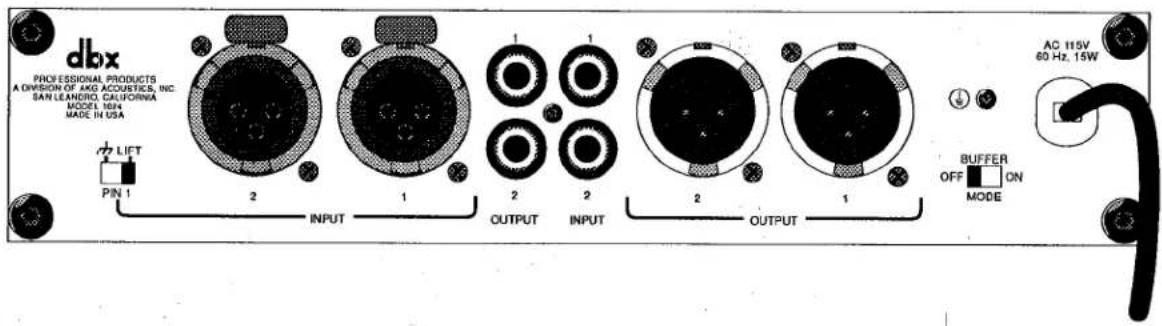
Figure 3: Rear Panel
PIN 1 Switch: This switch internally disconnects XLR INPUT pin 1 (both channels) from 1024 chassis ground to eliminate any ground loop hum problems that may arise. In the "LIFT" position these pins are disconnected and left floating. In the "GND" position, pin 1 of the input XLR connectors for both channels are connected to the 1024 chassis ground.
If necessary, an internal jumper on the 1024 can be set to isolate 1024 circuit ground from 1024 chassis ground if ground loop hum problems are caused by the equipment using the RCA connectors (See page 16).
XLR INPUT Jacks: The 3-pin XLR INPUT female jacks accept either balanced or unbalanced signals. Nominal input signal level is +4dBu and clip level is +28dBu. The XLR INPUT jacks accept XLR-type connectors, wired pin 2 HOT (+) and pin 3 COLD (−). Pin 1 is either connected to 1024 chassis ground or remains floating, depending on the position of the PIN 1 Switch.
IHF (RCA) INPUT Jacks: The two IHF (RCA) INPUT jacks of the 1024 are unbalanced. Nominal input signal level is -10dBV and clip level is typically +20dBV. Input impedance is 18kΩ. The RCA INPUT jacks accept standard RCA-type phono connectors.

Figure 4: Buffer Amplifier Rear Panel
IHF (RCA) OUTPUT Jacks: The two IHF (RCA) OUTPUT jacks of the 1024 are unbalanced, drive a nominal -10dBV into 10kΩ, and have a clip level of +20dBV. The RCA OUTPUT jacks accept standard RCA-type phono connectors.
XLR OUTPUT Jacks: The 3-pin XLR OUTPUT male jacks of the 1024 are driven by floating active-balanced amplifiers that simulate a true transformer balanced output. This allows for the load at the XLR OUTPUT to be either balanced, or single-ended (unbalanced) with very little difference (less than 0.5dB) in output level.
Either pin 2 or 3 of the XLR output connector can be grounded in this manner. Nominal output signal level is +4dBu into 600Ω, and typical maximum output signal level is +25dBu into a balanced 600Ω load. The XLR OUTPUT jacks are wired pin 2 HOT (+), pin 3 COLD (−) and pin 1 chassis GROUND and accept XLR-type connectors.
BUFFER MODE ON/OFF Switch: This rear panel slide switch sets the unit as a buffer amplifier for changing unbalanced +4dBu signals into balanced form. This switch selects either the RCA (-10dBV) inputs or XLR (+4dBu) inputs to drive the XLR outputs.
With the switch in the OFF position, the XLR inputs drive the RCA outputs (with 11.8dB of attenuation; adjustable ±10dB), and the RCA inputs drive the XLR outputs (with 11.8dB of gain; adjustable ±10dB).
With the switch in the ON position, the XLR inputs drive both the RCA outputs (where attenuation remains 11.8dB, adjustable ±10dB) and the XLR outputs (where gain now becomes 0dB, adjustable ±10dB), and the RCA inputs are disabled.
CHASSIS GROUND Screw: This rear panel screw provides the primary electrical connection between the chassis and the third wire of the line cord.
AC POWER Cable: Connect this cable to any AC power source of the correct frequency and line voltage as indicated on the rear panel. The 1024 consumes a maximum of 15 Watts AC power.
WARNING: Be sure to verify both your actual line voltage and the voltage for which your Model 1024 was wired, as indicated on the rear panel of your unit. Connection to an inappropriate power source may result in extensive damage which is not covered by the warranty.
CONNECTING THE 1024 TO YOUR SYSTEM
Basic Connection
Typically, the 1024 is used to provide balanced signals in systems using IHF unbalanced equipment, in order to reduce noise pickup and hum. The 1024 can present +4dBu balanced inputs and outputs to other (+4dBu balanced) equipment.
The 1024 can be connected for basic operation as shown in Figure 5. It can also be connected to your system as a two-way interface amplifier, line driver/buffer amplifier, signal splitter, or as an IHF distribution amp (Refer to the following pages).
For more specific installation information, refer to Installation Considerations, page 16.

For all connections, refer to the following steps:
A. Turn Off all equipment before making any connections.
B. Make connections via XLR and RCA jacks according to your requirements.
C. Plug in the AC power cable to power on the unit.
D. Verify that the rear panel BUFFER MODE ON/OFF switch is set correctly for your usage.
With the BUFFER MODE switch set to OFF, the XLR inputs drive the RCA outputs and the RCA inputs drive the XLR outputs. (With the switch set to ON, the XLR inputs drive both the RCA outputs and the XLR outputs, and the RCA inputs are disabled.)

flowchart
graph TD
    A["PROFESSIONAL AUDIO EQUIPMENT"] --> B["+4dBu SIGNAL TO XLR INPUTS"]
    B --> C["BALANCED INPUT"]
    C --> D["DBX"]
    D --> E["FROM RCA OUTPUTS"]
    E --> F["IHF EQUIPMENT"]
    F --> G["TO RCA INPUTS"]
    G --> H["BALANCED OUTPUT"]
    H --> I["Professional AUDIO EQUIPMENT"]
    D --> J["PROFESSIONAL AUDIO EQUIPMENT"]
    style A fill:#f9f,stroke:#333
    style F fill:#ccf,stroke:#333
    style I fill:#cfc,stroke:#333
Figure 5: Basic Connection
Two-Way Interface Amplifier
The 1024's basic connection can be taken one step further to build a two-way interface amplification system.
Set the rear panel BUFFER MODE switch to OFF, and simultaneously use the XLR inputs to drive the RCA outputs and the RCA inputs to drive the XLR outputs.

flowchart
graph TD
    A["dbx"] -->|Pin 1| B["2"]
    A -->|INPUT| C["1"]
    A -->|OUTPUT| D["2"]
    A -->|INPUT| E["3"]
    A -->|OUTPUT| F["2"]
    A -->|INPUT| G["1"]
    H["TAPE DECK"] -->|IN| I["0"]
    J["CD PLAYER"] -->|OUT| K["0"]
    L["MIXER OUTPUTS"] --> M["TO MIXER LINE INPUTS"]
    N["AC 115V 60 Hz, 15W"] --> O["2"]
    P["BUFFER ON MODE"] --> Q["2"]
    R["1024 REAR PANEL"] --> S["2"]
    T["PROFESSIONAL PROCES: A Dominator and Sonstice AC SANLEMONS CAUSYME MODEL TCP"] --> U["2"]
    V["1024 REAR PANEL"] --> W["2"]
    X["1024 REAR PANEL"] --> Y["2"]
    Z["1024 REAR PANEL"] --> AA["2"]
Figure 6: Two-Way Interface Amplifier
Line Driver/Buffer Amplifier
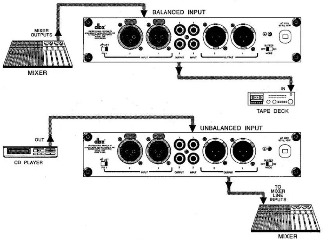
The 1024 can be used effectively as a line driver/buffer amp to adjust gain levels and to drive long lines. Use the front panel OUTPUT GAIN Controls to increase or decrease signal level.
With the rear panel BUFFER MODE switch set to OFF, the XLR inputs drive the RCA outputs and the RCA inputs drive the XLR outputs.
flowchart
graph TD
    A["MIXER OUTPUTS"] --> B["BALANCED INPUT"]
    B --> C["TAPE DECK"]
    C --> D["UNBALANCED INPUT"]
    D --> E["MIXER"]
    F["CD PLAYER"] --> G["OUT"]
    G --> H["TAPE DECK"]
    H --> I["UNBALANCED INPUT"]
    I --> J["MIXER"]
Figure 7: Line Driver
To buffer a +4dBu signal, set the BUFFER MODE switch to ON and connect the source to the XLR inputs. You will have a buffered +4dBu signal at the XLR outputs. Additionally, in BUFFER MODE, the RCA outputs provides a separate -10dBV buffered signal. (The RCA Inputs are disabled.)
Signal Splitter
The 1024 can be used to provide two balanced outputs from a single unbalanced mono signal. Simply use a "Y" connector to split the mono signal and connect it to the RCA inputs. The rear panel BUFFER MODE switch must be set to OFF.
IHF Distribution Amp
The 1024 can be used as a 2 to 4 IHF distribution amp when two unbalanced signals are presented to the XLR inputs. Set the rear panel BUFFER MODE switch to ON and connect the source to the XLR inputs. You will have a +4dBu signal at the XLR outputs and a -10dBV signal at the RCA outputs.

flowchart
graph TD
    A["DBX PROFESSIONAL PRODUCTS A DIVISION OF INC ACQUITIES, INC SWITCHED CAN LINDER, METER 150K MODE IN USA"] --> B["MIXER OUTPUTS"]
    B --> C["TAPE DECK"]
    C --> D["DAT RECORDER"]
    D --> E["XLR IN"]
    E --> F["BUFFER ON MODE"]
    F --> G["AC 115V 60 Hz, 15W"]
    style A fill:#f9f,stroke:#333
    style B fill:#ccf,stroke:#333
    style C fill:#cfc,stroke:#333
    style D fill:#fcc,stroke:#333
    style E fill:#ffc,stroke:#333
    style F fill:#fcc,stroke:#333
    style G fill:#cff,stroke:#333
Figure 8: IHF Distribution Amplifier
INSTALLATION CONSIDERATIONS
Input Termination and Grounding Jumpers (OPTIONAL)
As shipped from the factory, the 1024 has two HI-Z XLR inputs and the circuit ground is connected directly to earth ground.
If any of these options are not appropriate for your installation, the internal jumpers can be reset by a qualified technician. To reset the jumpers, remove the top cover to access the main circuit board. Do this by removing the four rear panel screws holding the cover in place; then lift the cover off.
Be sure power is disconnected before removing the cover.

When replacing the cover, tighten all the screws so they are snug. (Be careful not to strip the threads by over-tightening.)
A. 600Ω Input Termination.
[Skip this step if you want the 1024's XLR inputs to be HI-Z inputs, as shipped.]
To present a 600Ω load on the XLR input lines, set both jumpers J7 and J8 to the 600Ω TERMINATE position.
See Figure 9 to locate and set jumpers J7 and J8.
B. Grounding Configuration.
[Skip this step if you want the 1024's circuit ground connected directly to earth ground, as shipped.]
To disconnect circuit ground from earth ground, set jumper J6 to FLOAT position.
See Figure 9 to locate and set jumper J6.

CAUTION
The installation and servicing instructions in this manual are for use by qualified personnel only. To avoid electric shock do not perform any servicing other than that contained in the Operating Instructions unless you are qualified to do so. Refer all servicing to qualified service personnel.

GROUNDING JUMPER


Figure 9: 1024 Jumper Positions
Mounting the 1024 in a 1U Rack Space
The 1024 requires one rack space (height) and 12 rack space (width). It can be mounted above or below anything that doesn't generate excessive heat, since it requires no special ventilation. Ambient temperatures should not exceed 113°F (45°C) when equipment is powered. Hardware for mounting your 1024 is provided in the Accessory Kit included in your 1024 package.
Two 1024 units may be mounted side-by-side in one rack space. In addition, all dbx "half-rack" units share a mounting scheme. As a result, any dbx Performer Series signal processor (163X Compressor/Limiter, 263X De-Esser, 363X Dual Noise Gate, 463X OverEasy Noise Gate, or 563X Hiss Reducer) may be mounted next to the 1024 to save rack space. A dbx 150X Type I or 140X Type II Noise Reduction unit may also be mounted next to the 1024. Hardware for side-by-side mounting is included with each half-rack product. If the rubber feet were previously installed, they should be removed at this time.

Caution: Never remove the cover. There are no user-serviceable parts inside, and you run the risk of an electric shock.
To install a single 1024 (left or right side)

Figure 10: Rack Mounting One 1024 Unit
| You will need: | 1 | blank black panel |
| 1 | rack ear | |
| 1 | blank panel adaptor piece | |
| 1 | ^3/_32 " Allen wrench | |
| 1 | Phillips screwdriver (not included) | |
| 4 | pan head Phillips screws | |
| 2 | hex head screws |
NOTE: Your 1024 Accessory Kit includes the tools and hardware listed above, except as noted.
A. Use a Phillips screwdriver to loosely attach the single rack ear to either side of the 1024 with two pan head Phillips screws.
NOTE: If this is the first time the rack ear has been installed, you will be cutting threads as you drive the screws. This is normal.
B. Loosely attach the adaptor piece to the other side of the 1024 using two more pan head Phillips screws and a Phillips screwdriver. See note directly above.
C. Loosely attach the blank panel and adaptor piece using an Allen wrench and two hex head screws.
D. Align everything on a flat surface and tighten the screws with a Phillips screwdriver and the hex wrench.
To install two units side-by-side
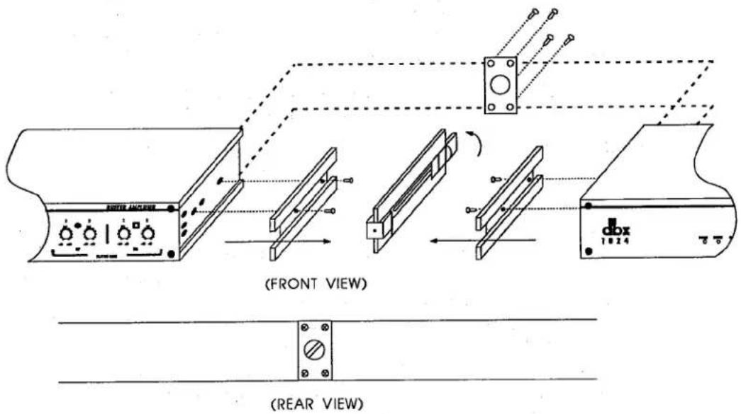
Figure 11: Rack Mounting Two 1024 Units
| You will need: | 1 | joiner assembly (joiner, joiner side pieces) |
| 1 | reinforcing plate | |
| 2 | rack ears | |
| 1 | ^3/_32 " Allen wrench | |
| 1 | Phillips screwdriver (not included) | |
| 4 | pan head Phillips screws | |
| 4 | flat head countersink screws |
NOTE: Your 1024 Accessory Kit includes the tools and hardware listed above, except as noted.
A. Remove the joiner assembly from the Accessory Kit that was supplied with each unit. Note how the joiner side pieces are held together by the joiner before you separate them. This is important when it comes time to join the units together. Now separate the joiner side pieces from the joiner by turning the thumbscrew counterclockwise.
B. At this time you will need to designate a "Left" and a "Right" unit.
C. With the left unit facing you, loosely attach a rack ear to the left side of the unit with two pan head Phillips screws. On the right side of the unit, place a joiner side piece into the extruded channel so the holes in the unit align with the holes in the joiner side piece — countersink side up. Secure the joiner side piece with two countersink screws.
NOTE: If this is the first time the rack ear has been installed, you will be cutting threads as you drive the screws. This is normal.
D. Repeat step "C" with the "Right" unit; swapping right for left with regard to the rack ear mounting and left for right with regard to the joiner side piece mounting.
E. Place the Left and Right units on a flat surface, rear facing, so the joiner side pieces are approximately 2" apart. Take the joiner assembly and loosen the thumbscrew so the sliding catches clear the joiner side-piece cut-outs. Now place the joiner assembly against one of the units with the side piece so it lays flush. (The joiner assembly should be positioned so the thumbscrew is accessible from the rear of the unit.) While holding the joiner assembly in position, slide the other unit over so it mates flush with the joiner assembly and turn the thumbscrew clockwise until it is snug. Do not over-tighten. Both units should now be secured together.
F. Make sure everything is aligned, and tighten the screws on each of the two rack ears.
NOTE: For installations where the two units will be subjected to physical stress (e.g. portable operations), a small OPTIONAL reinforcement plate is included. See steps G through I. If you do not wish to use the reinforcing plate, skip the following steps.
G. Turn the two units so that the back faces you. Remove the four rear cover screws nearest the joiner knob.
H. Place the reinforcing plate over the joiner knob so that the four screw holes line up.
I. Replace the four screws, using the slightly longer screws provided in the Accessory Kit.
Input/Output Cable Configurations
Hookups and Cabling
The 1024 is designed for nominal +4dBu levels at its XLR jacks and nominal -10dBV levels at its RCA phono jacks. Inputs can be used with either balanced or unbalanced sources and outputs can be used with either balanced or unbalanced loads, provided you use proper cabling.
NOTE: XLR connectors can support balanced or unbalanced signals.
RCA connectors can only support unbalanced signals.
A balanced line is defined as two-conductor shielded cable with the two center conductors carrying the same signal but of opposite polarity with respect to ground. An unbalanced line is generally a single-conductor shielded cable with the center conductor carrying the signal and the shield at ground potential.
Connect Audio Inputs
Figures 12 and 13 show cables for connecting balanced and unbalanced signal sources to the 1024 audio inputs. Refer to the type of operation and connectors you are using.
The XLR input connectors of the 1024 can be driven with either balanced or unbalanced signal lines up to +28dBu maximum with excellent results. The input impedance depends on the balance of the driving signal with respect to circuit ground of the 1024. If the signal is balanced with respect to 1024 circuit ground, the input impedance is 40kΩ. If the signal is single-ended (unbalanced) to 1024 circuit ground, the input impedance is 20kΩ.
The XLR input connectors, which are in phase with the XLR output connectors, are wired pin 2 HOT (+) and pin 3 COLD (−) with respect to the RCA input and output connectors.
A rear panel switch is provided on the 1024 to either connect pin 1 of the XLR input connectors to chassis ground, or float pin 1 of the XLR input connectors if hum is a problem. This switch allows troubleshooting of hum and other grounding problems without having to change the cabling. We advise starting with the switch in the LIFT position (Pin 1 floating; disconnected at the 1024 input) to avoid potential ground loops.
The RCA input connectors of the 1024 are unbalanced, meaning the outside conductor is electrically connected to the circuit ground of the 1024. The remaining conductor is HOT (+) and therefore in phase with pin 2 of the XLR connectors. Input impedance is 18k
The circuit ground of the 1024 is normally connected internally to chassis ground. However, if hum is a problem, this connection can be removed by repositioning an internal jumper (See page 16).

MONO PHONE PLUG TO MALE XLR-TYPE
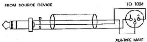
STEREO PHONE PLUG TO MALE XLR-TYPE

PHONO PLUG TO MALE XLR-TYPE
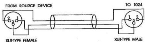
FEMALE XLR-TYPE TO MALE XLR-TYPE
Figure 12: Input Connections (To 1024 XLR Inputs)
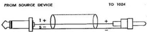
MONO PHONE PLUG TO PHONO PLUG
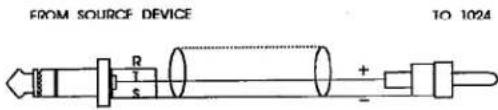
STEREO PHONE PLUG TO PHONO PLUG

PHONO PLUG TO PHONO PLUG
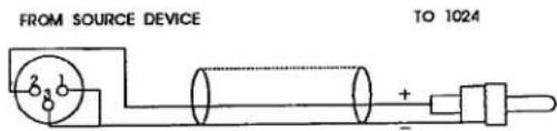
XLR-TYPE FEMALE
FEMALE XLR-TYPE TO PHONO PLUG
Figure 13: Input Connections (To 1024 RCA Inputs)
Connect Audio Outputs
Figures 14 and 15 show cables for connecting the 1024 audio outputs to balanced and unbalanced loads. Refer to the type of operation and connectors you are using.
The XLR output connectors of the 1024 can drive either balanced or unbalanced lines with excellent results. Typical driving capability into a balanced 600Ω load is +25dBu, and into an unbalanced 600Ω load is +23dBu. In either case, output impedance is 30Ω. Due to the floating characteristic of the active electronic output amplifiers, it is unnecessary to use transformers at the outputs. The XLR output connectors, which are in phase with the XLR input connectors, are wired pin 2 HOT (+) and pin 3 COLD (−) with respect to the RCA input and output connectors.

FEMALE XL-TYPE TO MONO PHONE PLUG
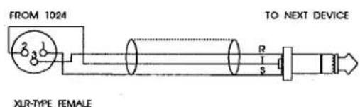
FEMALE XLR-TYPE TO STEREO PHONE PLUG
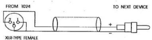
FEMALE XLR-TYPE TO PHONO PLUG

FEMALE XLR-TYPE TO MALE XLR-TYPE
Figure 14: Output Connections (From 1024 XLR Outputs)
The RCA output connectors of the 1024 are unbalanced, meaning the outside conductor is electrically connected to the circuit ground of the 1024. The remaining conductor is HOT (+) and therefore in phase with pin 2 of the XLR connectors. Output impedance is 50Ω. The circuit ground of the 1024 is normally connected internally to chassis ground. However, if hum is a problem, this connection can be removed by repositioning an internal jumper (See page 16).

PHONO PLUG TO MONO PHONE PLUG
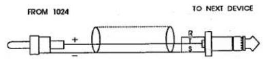
PHONO PLUG TO STEREO PHONE PLUG
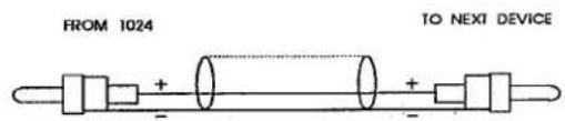
PHONO PLUG TO PHONO PLUG

XLR-TYPE MALE
PHONO PLUG TO MALE XLR-TYPE
Figure 15: Output Connections (From 1024 RCA Outputs)

Connecting Power
A. Check the line voltage.
The 1024 is shipped for 115V or 230V, 50 or 60Hz operation. Refer to the unit's rear panel to verify your unit's precise line voltage.
B. Connect the 1024's power cord to an appropriate AC power source.
MAINTENANCE, TROUBLESHOOTING
The 1024 is an all-solid-state product with components chosen for high performance and excellent reliability. Each 1024 is tested, burned in and calibrated at the factory and should require no adjustment of any type throughout the life of the unit. We recommend that your 1024 be returned to the factory should circumstances arise which necessitate repair or recalibration.
TECHNICAL SUPPORT, FACTORY SERVICE
Technical Support
If you require technical support, contact dbx customer service. Be prepared to accurately describe the problem. Know the serial number of your unit — this is printed on a sticker attached to the rear panel.
Telephone: (1) 510/351-3500
or Fax: (1) 510/351-1001
or Write: dbx Professional Products a division of AKG Acoustics, Inc. 1525 Alvarado Street San Leandro, CA 94577 USA
ATTN: Customer Service Department
Factory Service
Before you return a product to the factory for service, we recommend you refer to the manual. Make sure you have correctly followed installation steps and operation procedures. If you are still unable to solve a problem, contact our Customer Service Department for consultation. Often, a problem is relatively simple and can be quickly remedied after telephone consultation. If you need to return a product to the factory for service, include a letter describing the problem.
Please refer to the terms of your Limited Two-Year Standard Warranty, which extends to the first end-user. After expiration of the warranty, a reasonable charge will be made for parts, labor, and packing if you choose to use the factory service facility. In all cases, you are responsible for transportation charges to the factory. dbx will pay return shipping if the unit is still under warranty.
Use the original packing material if it is available.
Mark the package with the name of the shipper, and with these words in red:
DELICATE INSTRUMENT, FRAGILE!
Insure the package properly. Ship prepaid, not collect. Do not ship parcel post.
Warranty
The warranty, which can be enjoyed only by the first end-user of record, is stated on the separate Warranty Certificate packed with this manual. Save it for future reference. Details on obtaining factory service are provided above.
SPECIFICATIONS
(NOTE: 0dBV = 1.0VRMS; 0dBu = 0.775VRMS)
| RCA Inputs (Unbalanced IHF) | Input Impedance: 18kΩNominal Input Level: -10dBVMaximum Input Level: +18dBV |
| RCA Outputs (Unbalanced IHF) | Output Impedance: 50ΩNominal Output Level (into ≥10kΩ): -10dBVMaximum Output Level (into ≥10kΩ): +18dBV |
| XLR Inputs | Input Impedance: 40kΩ (balanced), 20kΩ (unbalanced)Nominal Input Level: +4dBuMaximum Input Level: +28dBu |
| XLR Outputs | Output Impedance: 30Ω (balanced or unbalanced)Nominal Output Level (into ≥600Ω): +4dBuMaximum Output Level (into ≥600Ω): +25dBu (balanced)+22dBu (unbalanced) |
| Nominal GainBUFFER MODE OFF | +11.8dB (RCA to XLR), -11.8dB (XLR to RCA) |
| BUFFER MODE ON | 0dB (XLR to XLR), -11.8dB (XLR to RCA) |
| Gain Adjustment Range | ±10dB Nominal Gain |
| Frequency Response | 20Hz to 20kHz (±0.25dB) |
| Bandwidth | -3dB @ 0.15Hz and 200kHz |
| THD | 0.005% @ 1kHz, nominal levels |
| Common MODE Rejection | >50dB, 50 - 60Hz |
| Dynamic Range | >100dB |
| Interchannel Crosstalk | -90dB @ 1kHz, -70dB @ 15kHz |
| Polarity | Pin 2 Hot |
| Output Short Circuit DurationWith Maximum Input | Indefinite |
| R.F. Attenuation | All inputs and outputs are RFI suppressed |
| Operating Voltage | DO: 96 - 125VAC; 50/60HzEU: 180 - 250VAC; 50/60Hz |
| Operating Temperature | 0°C to 45°C |
| Dimensions (H x W x D) | 1.75" x 8.5" x 7.25" 4.45cm x 21.59cm x 18.42cm) |
| Rack Space | 12 Rack Unit (1U High) |
| Weight | Net Weight: 3.0 lbs; 1.36 kgShipping Weight: 5.5 lbs; 2.49 kg |
| Warranty | dbx standard two-year warranty |
Specifications are subject to change.
SCHEMATICS
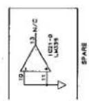
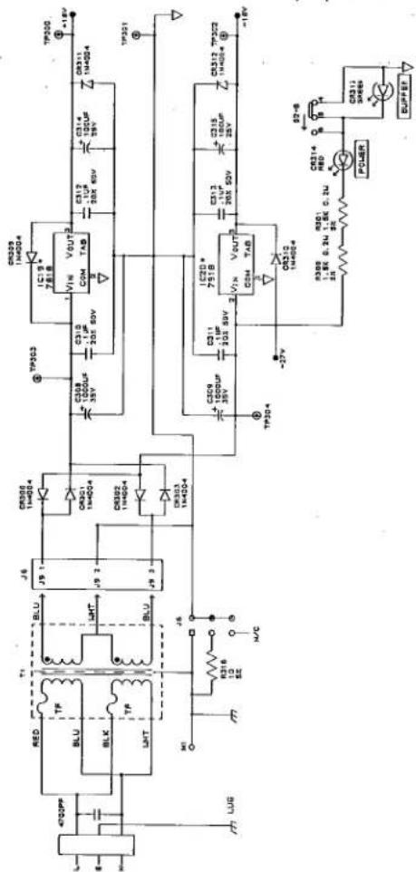
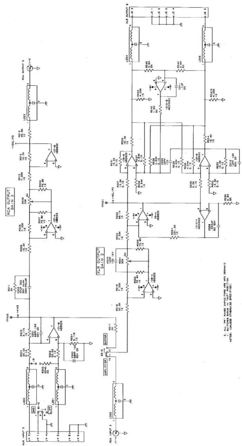
Schematics for the 1024 Main Board, Power Supply and Display are provided on the following pages.

- D.IUP CAPACITORS ARE MONOLYTIC CERAMIC
- ** INDICATES HEATSINK USED ON DEVICE
- SWITCHES SHOWN IN "OUT" POSITION NOTES: (UNLESS OTHERWISE SPECIFIED)




- CONTENTS
- QUICK SETUP
- INSPECTION
- Unpack and Inspect the 1024 package.
- Please complete the Registration Card and return it.
- INTRODUCTION
- Features
- The 1024 features:
- OPERATION
- Front Panel
- CONNECTING THE 1024 TO YOUR SYSTEM
- Two-Way Interface Amplifier
- Line Driver/Buffer Amplifier
- Signal Splitter
- IHF Distribution Amp
- INSTALLATION CONSIDERATIONS
- Input Termination and Grounding Jumpers (OPTIONAL)
- CAUTION
- Mounting the 1024 in a 1U Rack Space
- Input/Output Cable Configurations
- Hookups and Cabling
- Connect Audio Inputs
- Connect Audio Outputs
- Connecting Power
- MAINTENANCE, TROUBLESHOOTING
- TECHNICAL SUPPORT, FACTORY SERVICE
- Technical Support
- Factory Service
- Warranty
- SPECIFICATIONS
- SCHEMATICS
Brand : DBX
Model : 1024
Category : Processor