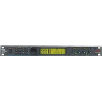
DDP - Processor DBX - Free user manual and instructions
Find the device manual for free DDP DBX in PDF.


| Product Type | Audio Dynamics Processor |
| Brand | DBX |
| Model | DDP |
| Inputs | 1/4" TRS and XLR balanced |
| Outputs | 1/4" TRS and XLR balanced |
| Frequency Response | 20 Hz – 20 kHz (±0.5 dB) |
| Dynamic Range | >108 dB (A-weighted) |
| THD+N | <0.008% at 1 kHz, +4 dBu |
| Power Supply | AC 100-240 V, 50/60 Hz, 20 W |
| Dimensions (W×H×D) | 19" × 1.75" × 6" (483 × 44 × 152 mm) |
| Weight | 5.5 lb (2.5 kg) |
| Key Features | Compressor, Limiter, De-esser, Gate, Peak & RMS modes |
| Controls | Threshold, Ratio, Attack, Release, Gain, Bypass |
| Indicators | LED gain reduction meter, power LED, bypass LED |
| Construction | Steel chassis, rackmountable with included brackets |
| Operating Temperature | 0°C to 40°C |
| Cleaning | Use a dry, soft cloth. Do not use solvents. |
| Safety | Class I equipment; connect to grounded outlet only. |
| Spare Parts | Order via authorized DBX service centers. Common parts: knobs, LEDs, power supply. |
| General Information | Designed for studio and live sound dynamics control. |
Frequently Asked Questions - DDP DBX
User questions about DDP DBX
0 question about this device. Answer the ones you know or ask your own.
Ask a new question about this device
Download the instructions for your Processor in PDF format for free! Find your manual DDP - DBX and take your electronic device back in hand. On this page are published all the documents necessary for the use of your device. DDP by DBX.
USER MANUAL DDP DBX
PROFESSIONAL PRODUCTS

CAUTION
RISK OF ELECTRIC SHOCK DO NOT OPEN

ATTENTION: RISQUE DE CHOC ELECTRIQUE - NE PAS OUVRIR
WARNING: TO REDUCE THE RISK OF FIRE OR ELECTRIC SHOCK DO NOT EXPOSE THIS EQUIPMENT TO RAIN OR MOISTURE
The symbols shown above are internationally accepted symbols that warn of potential hazards with electrical products. The lightning flash with arrowpoint in an equilateral triangle means that there are dangerous voltages present within the unit. The exclamation point in an equilateral triangle indicates that it is necessary for the user to refer to the owner's manual.
These symbols warn that there are no user serviceable parts inside the unit. Do not open the unit. Do not attempt to service the unit yourself. Refer all servicing to qualified personnel. Opening the chassis for any reason will void the manufacturer's warranty. Do not get the unit wet. If liquid is spilled on the unit, shut it off immediately and take it to a dealer for service. Disconnect the unit during storms to prevent damage.
WARNING
FOR YOUR PROTECTION, PLEASE READ THE FOLLOWING:
WATER AND MOISTURE: Appliance should not be used near water (e.g. near a bathtub, wash-bowl, kitchen sink, laundry tub, in a wet basement, or near a swimming pool, etc). Care should be taken so that objects do not fall and liquids are not spilled into the enclosure through openings.
POWER SOURCES: The appliance should be connected to a power supply only of the type described in the operating instructions or as marked on the appliance.
GROUNDING OR POLARIZATION: Precautions should be taken so that the grounding or polarization means of an appliance is not defeated.
POWER CORD PROTECTION: Power supply cords should be routed so that they are not likely to be walked on or pinched by items placed upon or against them, paying particular attention to cords at plugs, convenience receptacles, and the point where they exit from the appliance.
SERVICING: To reduce the risk of fire or electric shock, the user should not attempt to service the appliance beyond that described in the operating instructions. All other servicing should be referred to qualified service personnel.
FOR UNITS EQUIPPED WITH EXTERNALLY ACCESSIBLE FUSE RECEPTACLE: Replace fuse with same type and rating only.
MULTIPLE-INPUT VOLTAGE: This equipment may require the use of a different line cord, attachment plug, or both, depending on the available power source at installation. Connect this equipment only to the power source indicated on the equipment rear panel. To reduce the risk of fire or electric shock, refer servicing to qualified service personnel or equivalent.
U.K. MAINS PLUG WARNING
A moulded mains plug that has been cut off from the cord is unsafe. Discard the mains plug at a suitable disposal facility. NEVER UNDER ANY CIRCUM-STANCES SHOULD YOU INSERT A DAMAGED OR CUT MAINS PLUG INTO A 13 AMP POWER SOCKET. Do not use the mains plug without the fuse cover in place. Replacement fuse covers can be obtained from your local retailer. Replacement fuses are 13 amps and MUST be ASTA approved to BS1362.
ELECTROMAGNETIC COMPATIBILITY
This unit conforms to the Product Specifications noted on the Declaration of Conformity. Operation is subject to the following two conditions:
- this device may not cause harmful interference, and
- this device must accept any interference received, including interference that may cause undesired operation.
Operation of this unit within significant electromagnetic fields should be avoided.
- use only shielded interconnecting cables.
SAFETY INSTRUCTIONS
NOTICE FOR CUSTOMERS IF YOUR UNIT IS EQUIPPED WITH A POWER CORD.
WARNING: THIS APPLIANCE MUST BE EARTHED.
The cores in the mains lead are coloured in accordance with the following code:
GREEN and YELLOW - Earth
BLUE - Neutral
BROWN - Live
As colours of the cores in the mains lead of this appliance may not correspond with the coloured markings identifying the terminals in your plug, proceed as follows:
- The core which is coloured green and yellow must be connected to the terminal in the plug marked with the letter E, or with the earth symbol, or coloured green, or green and yellow.
- The core which is coloured blue must be connected to the terminal marked N or coloured black.
- The core which is coloured brown must be connected to the terminal marked L or coloured red.
This equipment may require the use of a different line cord, attachment plug, or both, depending on the available power source at installation. If the attachment plug needs to be changed, refer servicing to qualified service personnel who should refer to the table below. The green/yellow wire shall be connected directly to the unit's chassis.
| CONDUCTOR | WIRE COLOR | ||
| Normal Alt | |||
| L | LIVE | BROWN | BLACK |
| N | NEUTRAL | BLUE | WHITE |
| E | EARTH GND | GREEN/YEL | GREEN |
WARNING: If the ground is defeated, certain fault conditions in the unit or in the system to which it is connected can result in full line voltage between chassis and earth ground. Severe injury or death can then result if the chassis and earth ground are touched simultaneously.
DECLARATION OF CONFORMITY
Manufacturer's Name: Manufacturer's Address:
dbx Professional Products 8760 S. Sandy Parkway Sandy, Utah 84070, USA
declares that the product:
dbx DDP
conforms to the following Product Specifications:
Safety: EN 60065 (1993) IEC65 (1985) with Amendments 1, 2, 3
EMC: EN 55013 (1990) EN 55020 (1991)
Supplementary Information:
The product herewith complies with the requirements of the Low Voltage Directive 73/23/EEC and the EMC Directive 89/336/EEC as amended by Directive 93/68/EEC.
dbx Professional Products Vice-President of Engineering 8760 S. Sandy Parkway Sandy, Utah 84070, USA March 31, 1998
European Contact: Your Local dbx Sales and Service Office or
International Sales Office 68 Sheila Lane Valparaiso, Indiana 46383, USA Tel: (219) 462-0938 Fax: (219) 462-4596
Manual Contents
Section 1: Introduction .....2
Unpack 2
Quickstart 2
Section 2: The DDP Tour .....3
Hardware 3
Front Panel / Display .....3
Rear Panel 3
Signal Flow 4
Software 5
Setups and Programs .....5
Gate Section 5
Compressor Section .....5
De-essing Section 5
Limiting Section .....5
Sidechain EQ Section .....5
Section 3: Setup / Basic Operation ..6
Analog Connections 6
Digital Connections 6
Midi Connections 7
The Curve Window .....7
Software Navigation 8
Threshold Metering 8
Operating Modes .....9
Program Mode .....9
The Bypass Button .....10
Setup Mode 10
Ext. S-chain and the Digital Meters .11
Viewing Elements of a Chain .....13
Linked Programs .....13
Dual-mono Programs .....13
Section 4: Editing/Recalling/Saving
Presets 14
The Store Button .....14
Moving Around 14
Editing Gates 14
Editing Compressors 15
Editing Limiters .....17
Editing De-Essers .....18
Editing the Sidechain EQ .....18
More About Sidechain EQ .....19
Changing Chain Types .....20
Saving Programs and Setups .....20
Saving a Program .....20
Saving a Setup .....21
Replace Old 21
Store New .....21
Section 5: Utility Functions .....23
Contrast 23
Sample Rate .....23
AutoLoad 23
Digital Input Mode .....23
Digital Output Mode .....24
Digital Input Level Controls .....24
MIDI 24
SysEx 24
A/D Calibration .....24
Section 6: Appendices .....25
APPENDIX 1: Misc. Information .....25
Hard Reset 25
Change Default Startup Program .....25
Front Panel Lockout .....25
TYPE IV™ Conversion System .....25
TSE™ Tape Saturation Emulation .....25
TCM ^TM Transient Capture Mode .....26
APPENDIX 2: Factory Setup Listing .....27
APPENDIX 3: Factory Program Listing ....29
APPENDIX 4: MIDI/SysEx/CC Guide .....30
Midi Basics 30
MIDI Channels 30
MIDI Changes 30
Continuous Controller Listing .....30
SysEx Basics 31
General Format 31
Hex Value Definitions .....31
Procedures 31
SysEx Program Dump Sample .....34
APPENDIX 5: Factory Service / Warranty . . .35
APPENDIX 6: Specifications .....36
Section 1: Introduction
Congratulations on your purchase of the dbx DDP Digital Dynamics Processor. For over 25 years dbx has been the industry leader in dynamics processing. With the introduction of the DDP, we take that same leadership into the digital domain. We are sure you will find the DDP able to meet all your dynamics control needs.
This manual will be your key to understanding the full functionality of the powerful DDP. Read it carefully. After you have become familiar with the unit, we encourage you to experiment and find creative ways that the DDP can make you a better musician and engineer.
Unpack
Your DDP was carefully manufactured, tested, burned in, and packaged at the dbx factory. Before you proceed further, make sure the following items are included in your packaging:
- dbx DDP Digital Dynamics Processor
- Operator's manual
- Power cord
- Warranty registration card
You should save all packaging materials if possible. They were designed to protect the unit during shipping, and in the unlikely event that your DDP should require service, use only the factory packaging to return it to the factory.
Quickstart
If you are one who prefers to plug and play and read later, follow these simple instructions for setting up the DDP, and get on your way:
- Make sure that AC power is not connected to the DDP. Turn off the power to your console, recorder, and other devices in your setup.
- Make audio connections in one of several ways:
A. Wire the analog inputs and outputs into a patch bay. This method will prove to be the most useful in the long run.
B. Connect the DDP's inputs and outputs directly to the insert point of a console's input strip, group output, auxiliary send and return, or main outputs.
C. Connect the DDP's input to another device's outputs, and connect the DDP's outputs to the line inputs of a console.
-
With the power switch in the OFF position, connect the power cable (included) to the DDP.
-
Press the LightPipe METER SELECT switch IN to select the INPUT meters for the analog signal. Turn the analog audio input level pots all the way to the OFF (-∞) position (fully counter-clockwise). Apply power to the other devices in the setup first, then the DDP. The DDP "wakes up" in the default program mode. You may use the large wheel to the right of the screen to scroll through the various programs.
-
When you have a program selected that suits your application, you can start making sound: make sure there is signal arriving at the DDP's input, and begin to turn up the INPUT level pots until the LightPipe input meters are peaking at, but not above "+12". And away you go!
FOR OPTIMUM PERFORMANCE FROM THE DDP, MAKE SURE TO USE PROPER INPUT LEVELS.
Section 2: The DDP Tour
HARDWARE
Front Panel

Analog Input and Output Level Controls
These controls adjust the analog audio levels of the DDP at the input and output stages. Note that the analog output level controls do not affect any digital processing or digital output levels. However, the analog outputs still function while the digital outputs are engaged.
Meter Select Switches
These lightpipe switches select between analog input and output monitoring for the Level Meters.
Level Meters
These meters monitor either analog input or output, depending on the orientation of the Meter Select Buttons.
LCD Display
The large LCD display shows the program, curve, digital meters, parameters, and modules selected by the Function Buttons and the Data Wheel.
Data Wheel
The Data Wheel changes selected parameters, programs and modules.
Function Buttons
The Function buttons activate the programs, modules, utilities, and parameters of the DDP.
Power Switch
Turns the DDP on and off.
Rear Panel

IEC Power Cord Receptacle
IEC Power Cord Receptacle.
Digital I/O (Optional)
The optional Digital I/O card provides digital input and output capabilities in either AES/EBU or S/PDIF formats at 24bit word lengths.
MIDI In and Out/Thru Connectors
These connectors provide full MIDI functionality to the DDP. The Out/Thru jack allows you to use the DDP at any point in the MIDI chain. All automation functions are accessed through the MIDI connectors.
Analog Inputs and Outputs
Each analog channel features both XLR and 1/4" TRS electronically balanced inputs and outputs. They may be used in a balanced or unbalanced configuration. To use unbalanced signal, use a 1/4" TS jack, or ground pin 3 of the XLR cable.
Section 2: The DDP Tour
Signal Flow
The following simple illustrations show how audio signal flows through the DDP, and how the LCD display works. They will help you to understand where the DDP's metering points are located, as well as identify the various elements of the LCD display.

flowchart
graph LR
    A["analog input"] --> B["analog input meter"]
    B --> C["A /D Converter"]
    C --> D["Dynamics Processor"]
    D --> E["D /A Converter"]
    E --> F["analog output meter"]
    F --> G["digital output"]
    C --> H["digital input control"]
    D --> I["digital input meter"]
    D --> J["digital input meter"]
    D --> K["digital input meter"]
    D --> L["digital input meter"]
    D --> M["digital input meter"]
    D --> N["digital input meter"]
    D --> O["digital input meter"]
    D --> P["digital input meter"]
    D --> Q["digital input meter"]
    D --> R["digital input meter"]
    D --> S["digital input meter"]
    D --> T["DSP (Software - based) Operations"]
    T --> U["DSP (Software - based) Operations"]
    U --> V["DSP (Software - based) Operations"]
    V --> W["DSP (Software - based) Operations"]
    W --> X["DSP (Software - based) Operations"]
    X --> Y["DSP (Software - based) Operations"]
    Y --> Z["DSP (Software - based) Operations"]
    Z --> AA["DSP (Software - based) Operations"]
    AA --> AB["DSP (Software - based) Operations"]
    AB --> AC["DSP (Software - based) Operations"]
    AC --> AD["DSP (Software - based) Operations"]
    AD --> AE["DSP (Software - based) Operations"]
    AE --> AF["DSP (Software - based) Operations"]
    AF --> AG["DSP (Software - based) Operations"]
    AG --> AH["DSP (Software - based) Operations"]
    AH --> AI["DSP (Software - based) Operations"]
    AI --> AJ["DSP (Software - based) Operations"]
    AJ --> AK["DSP (Software - based) Operations"]
    AK --> AL["DSP (Software - based) Operations"]
    AL --> AM["DSP (Software - based) Operations"]
    AM --> AN["DSP (Software - based) Operations"]
    AN --> AO["DSP (Software - based) Operations"]
    AO --> AP["DSP (Software - based) Operations"]
    AP --> AQ["DSP (Software - based) Operations"]
    AQ --> AR["DSP (Software - based) Operations"]
    AR --> AS["DSP (Software - based) Operations"]
    AS --> AT["DSP (Software - based) Operations"]
    AT --> AU["DSP (Software - based) Operations"]
    AU --> AV["DSP (Software - based) Operations"]
    AV --> AW["DSP (Software - based) Operations"]
    AW --> AX["DSP (Software - based) Operations"]
    AX --> AY["DSP (Software - based) Operations"]
    AY --> AZ["DSP (Software - based) Operations"]
    AZ --> BA["DSP (Software - based) Operations"]
    BA --> BB["DSP (Software - based) Operations"]
    BB --> BC["DSP (Software - based) Operations"]
    BC --> BD["DSP (Software - based) Operations"]
    BD --> BE["DSP (Software - based) Operations"]
    BE --> BF["DSP (Software - based) Operations"]
    BF --> BG["DSP (Software - based) Operations"]
    BG --> BH["DSP (Software - based) Operations"]
    BH --> BI["DSP (Software - based) Operations"]
    BI --> BJ["DSP (Software - based) Operations"]
    BJ --> BK["DSP (Software - based) Operations"]
    BK --> BL["DSP (Software - based) Operations"]
    BL --> BM["DSP (Software - based) Operations"]
    BM --> BN["DSP (Software - based) Operations"]
    BN --> BO["DSP (Software - based) Operations"]
    BO --> BP["DSP (Software - based) Operations"]
    BP --> BQ["DSP (Software - based) Operations"]
    BQ --> BR["DSP (Software - based) Operations"]
    BR --> BS["DSP (Software - based) Operations"]
    BS --> BT["DSP (Software - based) Operations"]
    BT --> BU["DSP (Software - based) Operations"]
    BU --> BV["DSP (Software - based) Operations"]
    BV --> BW["DSP (Software - based) Operations"]
    BW --> BX["DSP (Software - based) Operations"]
    BX --> BY["DSP (Software - based) Operations"]
    BY --> BZ["DSP (Software - based) Operations"]
    BZ --> CA["DSP (Software - based) Operations"]
    CA --> CB["DSP (Software - based) Operations"]
    CB --> CC["DSP (Software - based) Operations"]
    CC --> CD["DSP (Software - based) Operations"]
    CD --> CE["DSP (Software - based) Operations"]
    CE --> CF["DSP (Software - based) Operations"]
    CF --> CG["DSP (Software - based) Operations"]
    CG --> CH["DSP (Software - based) Operations"]
    CH --> CI["DSP (Software - based) Operations"]
    CI --> CJ["DSP (Software - based) Operations"]
    CJ --> CK["DSP (Software - based) Operations"]
    CK --> CL["DSP (Software - based) Operations"]
    CL --> CM["DSP (Software - based) Operations"]
    CM --> CN["DSP (Software - based) Operations"]
    CN --> CO["DSP (Software - based) Operations"]
    CO --> CP["DSP (Software - based) Operations"]
    CP --> CQ["DSP (Software - based) Operations"]
    CQ --> CR["DSP (Software - based) Operations"]
    CR --> CS["DSP (Software - based) Operations"]
    CS --> CT["DSP (Software - based) Operations"]
    CT --> CU["DSP (Software - based) Operations"]
    CU --> CV["DSP (Software - based) Operations"]
    CV --> CW["DSP (Software - based) Operations"]
    CW --> CX["DSP (Software - based) Operations"]
    CX --> CY["DSP (Software - based) Operations"]
    CY --> CZ["DSP (Software - based) Operations"]
Figure 1: DDP Signal Flow

bar
| Parameter | Value | | :--- | :--- | | Input | -6 | | Output | +4 | | 1 | Multi-Band Compressor Gate Gate Limiter 12345678910 Type IV™ | | 2 | Multi-Band Compressor Gate Limiter 12345678910 Type IV™ | | 3 | Multi-Band Compressor Gate Limiter 12345678910 Type IV™ | | 4 | Multi-Band Compressor Gate Limiter 12345678910 Type IV™ | | 5 | Multi-Band Compressor Gate Limiter 12345678910 Type IV™ | | 6 | Multi-Band Compressor Gate Limiter 12345678910 Type IV™ | | 7 | Multi-Band Compressor Gate Limiter 12345678910 Type IV™ | | 8 | Multi-Band Compressor Gate Limiter 12345678910 Type IV™ | | 9 | Multi-Band Compressor Gate Limiter 12345678910 Type IV™ | | 10 | Multi-Band Compressor Gate Limiter 12345678910 Type IV™ | | 11 | Multi-Band Compressor Gate Limiter 12345678910 Type IV™ | | 12 | Multi-Band Compressor Gate Limiter 12345678910 Type IV™ | | 13 | Multi-Band Compressor Gate Limiter 12345678910 Type IV™ | | 14 | Multi-Band Compressor Gate Limiter 12345678910 Type IV™ | | 15 | Multi-Band Compressor Gate Limiter 12345678910 Type IV™ | | 16 | Multi-Band Compressor Gate Limiter 12345678910 Type IV™ | | 17 | Multi-Band Compressor Gate Limiter 12345678910 Type IV™ | | 18 | Multi-Band Compressor Gate Limiter 12345678910 Type IV™ | | 19 | Multi-Band Compressor Gate Limiter 12345678910 Type IV™ | | 20:1 | Multi-Band Compressor Gate Limiter 12345678910 Type IV™ | | 21 | Multi-Band Compressor Gate Limiter 12345678910 Type IV™ | | 22 | Multi-Band Compressor Gate Limiter 12345678910 Type IV™ | | 23 | Multi-Band Compressor Gate Limiter 12345678910 Type IV™ | | 24 | Multi-Band Compressor Gate Limiter 12345678910 Type IV™ | | 25 | Multi-Band Compressor Gate Limiter 12345678910 Type IV™ | | 26 | Multi-Band Compressor Gate Limiter 12345678910 Type IV™ | | 27 | Multi-Band Compressor Gate Limiter 12345678910 Type IV™ | | 28 | Multi-Band Compressor Gate Limiter 12345678910 Type IV™ | | 29 | Multi-Band Compressor Gate Limiter 12345678910 Type IV™ | | 30 | Multi-Band Compressor Gate Limiter 12345678910 Type IV™ | | 31 | Multi-Band Compressor Gate Limiter 12345678910 Type IV™ | | 32 | Multi-Band Compressor Gate Limiter 12345678910 Type IV™ | | 33 | Multi-Band Compressor Gate Limiter 12345678910 Type IV™ | | 34 | Multi-Band Compressor Gate Limiter 12345678910 Type IV™ | | 35 | Multi-Band Compressor Gate Limiter 12345678910 Type IV™ | | 36 | Multi-Band Compressor Gate Limiter 12345678910 Type IV™ | | 37 | Multi-Band Compressor Gate Limiter 12345678910 Type IV™ | | 38 | Multi-Band Compressor Gate Limiter 12345678910 Type IV™ | | 39 | Multi-Band Compressor Gate Limiter 12345678910 Type IV™ | | 40 | Multi-Band Compressor Gate Limiter 12345678910 Type IV™ | | 41 | Multi-Band Compressor Gate Limiter 12345678910 Type IV™ | | 42 | Multi-Band Compressor Gate Limiter 12345678910 Type IV™ | | 43 | Multi-Band Compressor Gate Limiter 12345678910 Type IV™ | | 44 | Multi-Band Compressor Gate Limiter 12345678910 Type IV™ | | 45 | Multi-Band Compressor Gate Limiter 12345678910 Type IV™ | | 46 | Multi-Band Compressor Gate Limiter 12345678910 Type IV™ | | 47 | Multi-Band Compressor Gate Limiter 12345678910 Type IV™ | | 48 | Multi-Band Compressor Gate Limiter 12345678910 Type IV™ | | 49 | Multi-Band Compressor Gate Limiter 12345678910 Type IV™ | | 50 | Multi-Band Compressor Gate Limiter 12345678910 Type IV™ | | 51 | Multi-Band Compressor Gate Limiter 12345678910 Type IV™ | | 52 | Multi-Band Compressor Gate Limiter 12345678910 Type IV™ | | 53 | Multi-Band Compressor Gate Limiter 12345678910 Type IV™ | | 54 | Multi-Band Compressor Gate Limiter 12345678910 Type IV™ | | 55 | Multi-Band Compressor Gate Limiter 12345678910 Type IV™ | | 56 | Multi-Band Compressor Gate Limiter 12345678910 Type IV™ | | 57 | Multi-Band Compressor Gate Limiter 12345678910 Type IV™ | | 58 | Multi-Band Compressor Gate Limiter 12345678910 Type IV™ | | 59 | Multi-Band Compressor Gate Limiter 12345678910 Type IV™ | | 60 | Multi-Band Compressor Gate Limiter 12345678910 Type IV™ | | -60 | Gain Reduction meter (approximate) for the comparison graph; the difference between the two metrics is calculated using the gain reduction meter. The comparison graph shows the magnitude of the gain reduction meter relative to the difference between the two metrics. The comparison graph illustrates how the gain reduction meter is calculated using the gain reduction meter. The comparison graph also indicates that the difference between the two metrics is calculated using the gain reduction meter. The comparison graph includes a line graph on the right.Figure 2: DDP LCD display
Section 2: The DDP Tour
SOFTWARE
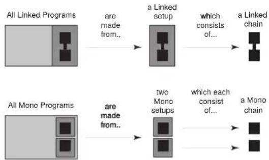
The DDP software works on a “building-block” philosophy. Every program number consists of a processing “setup” which is built from processing elements that make up a “chain”. The chain elements may be used in different combinations to produce a desired effect. Once the desired effect is reached, you may rename and save the setup to a user library area. The setup’s chain may consist of any or all of the following: gating effects, compression effects, limiting effects, parametric EQ, sidechain parametric EQ effects, and/or de-essing effects. There are several preset mono and linked setups. For a complete listing of the setups in the DDP, see section 6. Processing setups are linked together using True RMS Power Summing™ (see section 8) for superior stereo operation, or two separate setups may be used in dual mono mode. Each element of the chain has a full complement of parameters that can be manipulated very precisely via the Function buttons and the Data Wheel. The following figure shows the hierarchical building block system used in the DDP.
flowchart
graph LR
    A["All Linked Programs"] --> B["are made from.."]
    B --> C["a Linked setup"]
    C --> D["which consists of..."]
    D --> E["a Linked chain"]
    F["All Mono Programs"] --> G["are made from.."]
    G --> H["two Mono setups"]
    H --> I["which each consist of..."]
    I --> J["a Mono chain"]
Figure 3: Program Components
Setups and Programs
Setups are recalled, manipulated and stored individually. Setups must be recalled into programs before they can be accessed for use. Each program has a number assigned to it, and can consist of one or two setups: channel 1 and/or channel 2. Following is a brief description of the various processor elements that make up the DDP processing software.
Gate.
The gate is a dbx expander/gate which gives control over the "ramp" or ratio of the opening, There are also Attack, Hold, and Release times available. Transient Capture Mode™ is also found in the Gate section, with variable delay times available.
For a complete list of the parameters available in the gate, see section 4. For an explanation of Transient Capture Mode, and its implementation in the DDP, see Section 6.
Compressor:
The compressor offers comprehensive control over all parameters. OverEasy® is present, with a variable knee feature (VariKnee™) found only on the DDP. Auto attack and release, and a hold feature make the compressor more unique than other compressors.
For a complete list of the parameters available in the compressor, see section 4.
Limiter
The limiter offers precise control over Threshold, Attack, and Release. Release times are set in the measurement standard dB/ms.
For a complete description of the limiter, see section 4.
De-Esser:
The DDP's de-esser allows a wide frequency control range between 800Hz and 8kHz. The range is wide enough to accomplish the most demanding of de-essing needs.
For a complete list of the parameters available in the de-esser, see section 4.
Sidechain EQ / In-Line EQ:
The DDP offers you the ability to do EQ processing in the sidechain circuit without having to hook up an extra unit. It's easy to perform frequency-specific contouring functions all within the DDP's software. Also in the EQ section is the new TSE™ Tape Saturation Emulation algorithm, which works in tandem with the TYPE IV™ Conversion System to capture the essence of any analog signal in a pleasing way never accomplished before.
For an explanation of the EQ functions of the DDP, see section 4. For information on the TYPE IV™ Conversion System and its implementation in the DDP see Section 6.
Section 3: Setup / Basic Operation
ANALOG CONNECTIONS
The DDP is designed to interface as easily as possible to your system. To that end, it may be used in the insert path of a console, in a patch bay, or as a group output processor. Figure 4 shows the DDP used in an insert point of a console. Analog audio connections are made using standard XLR or 1/4" TRS cables. The rear panel is marked as "Channel One" and "Channel Two" to correspond to the way the DDP's software identifies the two channels of audio. If you are used to using the "left/right" identifiers and plan to use the DDP in such a system, just ensure that each channel of the DDP is consistent in its hookups between the inputs and the outputs (ie: if you use the DDP's Channel One input in the "left" side of your system, make sure that Channel One's output also goes to the "left" side of your system). Refer to the illustration of the DDP rear panel on the previous page.
The DDP uses wide ranging analog input and output gain pots that allow the use of either -10dBV or +4dBu connections without the use of a sensitivity selection switch.

Figure 4: DDP Insert Path Connections
DIGITAL CONNECTIONS
If you have purchased the optional digital input / output module for your DDP, you have the ability to perform complex dynamics processing tasks on digital signals without having to leave the digital domain. The DDP Digital I/O also offers the ability to convert analog to digital signals using the proprietary dbx TYPE IV™ Conversion System. The dbx TYPE IV™ algorithms capture an analog signal into the digital domain while maintaining the best qualities of an analog recording, and minimizing the sometimes harsh qualities of digital recordings.
When the digital card is installed in the DDP, the analog outputs are still operative, giving you simultaneous analog and digital output. When digital input is selected via the Utilities button, the analog inputs are disabled. For a complete description of the Utilities functions see Section 5.

Figure 5: The DDP rear panel
Section 3: Setup / Basic Operation
MIDI CONNECTIONS
The DDP has a full complement of MIDI functionality. The MIDI connectors on the Rear Panel are configured in the traditional way: with an "In" jack and an "Out/Thru" jack. The DDP can be used in common MIDI systems at any point in the MIDI chain. MIDI setup functions are accessed with the Utilities button and are generally the same as the functionality you are used to with most other MIDI devices. Program numbers and setups may be changed and bypassed via the standard MIDI commands. In addition, presets may be saved off of the DDP and reloaded via the MIDI functions. Full SysEx and Continuous Controller functions are also a part of the DDP's architecture. A full explanation of the MIDI, SysEx and CC functions are discussed in Section 5.
THE CURVE WINDOW
After you have chosen a program, you will want to change some of the parameters to meet your specific needs. One of the most useful tools available on the DDP for setting up a proper compression curve is the curve window. In the curve window you can see the combined effects of all compression-related parameters expressed in a graphical format. The figure below shows the different parts of the curve window you will see as you edit the gate, compressor, and limiter functions of the DDP.
When working with the sidechain EQ, or the in-line EQ, the curve window changes to show a graphical representation of the 3 parametric bands in a frequency grid. Your adjustments to the three bands are shown in real time.
Additionally, the de-esser has its own graphical way of displaying its parameters, as seen above. The frequency is shown on the bottom, or X axis, and the amount is shown on the side, or Y axis. Again, changes to the parameters are updated in real time.
![Output compressor threshold gap gate threshold Input limiter threshold compressor ratio limiter output Gate gate ratio Boost or Cut normal or unprocessed signal [1:1 ratio] Frequency Level 25Hz 800Hz 20K D+ -6 -12 -18 -24 800Hz 8k Frequency](/content/2026/06/1364046/images/e2aa9abb2fe8d8b06444a538f4531dd818b25cd92042f1ac9dec150e82656e23.jpg)
Figure 6: The compression curve window, the EQ window, and the De-Esser window
Section 3: Setup / Basic Operation
SOFTWARE NAVIGATION Threshold Metering
On every program, you will find threshold metering for each element of the processing setup. These take the same form as the now-standard dbx 10 Series processors' threshold meters: a plus (+) or minus (-) sign in a square box.
| C-+ | Compressor Threshold Meter |
| G-+ | Gate Threshold Meter |
| L-+ | Limiter Threshold Meter |
| D+ | De-Esser Threshold Meter |
Figure 7: The DDP's threshold meters
Compressor
For the compressor, the threshold meter has three segments. (See figure 7 above.) The first is the minus (-) sign. It indicates that the threshold that is set in the compressor section is not being exceeded by the program material. There is no processing taking place in the compressor section if the threshold is not being exceeded, no matter what the other compressor settings are. The next part of the threshold meter is the "o". It represents the OverEasy range of compression. When the signal level is in the OverEasy® range, the "o" part of the meter will be blackened, indicating that the signal is in the soft knee mode of compression. (For a complete explanation of the OverEasy® parameter, see section 4.) The third segment of the compressor meter is the plus (+) sign. It is blackened when the signal is being fully compressed at the ratio set by the Ratio Parameter control.
Limiter L-+
The limiter's threshold meter works on the same principle: when the signal is under the threshold setting (which is set in the limiter section), the signal is not being processed by the limiter section. If the DDP's screen shows that you are getting gain reduction, it is through some other chain element. To determine which element is triggering gain reduction, look at the other threshold meters to determine which element's threshold is being exceeded by the signal. When the signal exceeds the threshold set in the limiter section, the plus (+) sign will darken, and gain reduction will begin to occur as a result of the signal exceeding the limiter's threshold.
Gate
When the signal is under the threshold set in the gate section, the gate is "closed", or signal is not being passed through. The gate section is before the compressor and limiter sections in all chain types, and if the signal is not being passed through the gate, the other elements of the chain will not be activated. When the signal is under the threshold, the minus (-) sign is darkened, and when the signal passes over the threshold, the plus (+) sign is darkened
De-Esser
The De-esser also has a threshold meter. The threshold meter for this element is also displayed in the upper left corner. When the plus sign is reversed - white “+” on black background, the threshold has been exceeded and de-essing is being applied to the signal.
Section 3: Setup / Basic Operation
Operating Modes
Program Mode
The DDP comes ready to turn on in "Program Mode". There are a series of 50 factory programs, as well as enough room to name and store up to 50 of your own programs. The factory designed programs have been given obvious names, according to application and should be a good jumping off point for all of your processing needs. They cannot be erased. Their names and characteristics are listed in section 5. At the factory, the factory-designed programs were also copied into the re-writable user program area. A program can be erased at any time by saving a program in its place.
After you have set up and turned on the DDP, it will be in "program" mode and will show something like the following in the middle section of the LCD display screen:
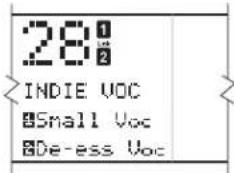
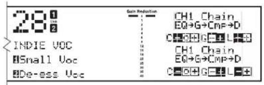
Figure 8: Sample display showing Program #28, Setup 1 is "small Voc" and Setup 2 is "De-Ess Voc".
The large number on the display indicates the program number. It is the method used to bookmark programs, and all programs have a program number. Each program can store either a linked setup, or two dual mono setups.
There are two ways to take a look at the setup for any program:
- While in "program" mode, the display will show the chain for each setup in the curve window, located on the far right side of the display. The abbreviation for each chain element is as follows:
Equalizer: EQ Gate: G Compressor: C or Cmp Limiter: L De-Esser: DS Sidechain EQ: SEQ

Figure 9: Display showing elements of each setup in a dual mono program.
Section 3: Setup / Basic Operation
- Press the "CH 1" or "CH 2" button, (depending on which setup you want to look at) while the "program" button's light is on. This method only lets you see the setup for one channel at a time. The contents of the setup, or the setup's chain, will be displayed in the third line of text. As you do this, the program LED will go off, and the LED on the button you pressed will light, indicating that you are now looking at channel one's (or two's) setup. In addition to this telemetry, there will be text which says "USER setup" or "FACTORY Setup" in the curve window on the far right side of the display. By turning the Data Wheel, you can scroll through them. You will notice the various factory setups as well as all your user setups. You can store up to 100 linked setups, and 100 mono setups. As you do more projects with your DDP, you will begin to gather all types of setups that you have designed and saved for yourself. You are now in "setup" mode. Using the Data Wheel, scroll through the available setups for the program you have chosen. You will see the 3 linked chain types if you are in a linked program number, or you will see the 6 chains for mono setups if you are in a dual mono program number.
To get out of setup mode and back to program mode, simply touch the program button. The LED associated with the Channel button will turn off and the Program button LED will turn on.

flowchart
graph TD
    A["CH 1"] --> B["NEXT PAGE"]
    C["CH 2"] --> D["EXP: GATE"]
    E["PROGRAM"] --> F["DE-ESSER SIDECHAIN : EQ UTILITYSELECT"]
    G["PROGRAM"] --> H["PROGRAM PREV PAGEORE BYPASS"]
    I["LOAD"] --> J["PROGRAM"]
    style A fill:#f9f,stroke:#333
    style C fill:#f9f,stroke:#333
    style E fill:#f9f,stroke:#333
    style G fill:#f9f,stroke:#333
    style I fill:#f9f,stroke:#333
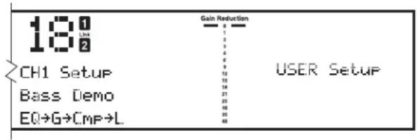
Figure 10: Function buttons and LCD display in chain mode.
While in program mode, you may scroll through the different factory designed programs by simply turning the Data Wheel. By default, the DDP is shipped with the AutoLoad feature activated. This means that the program number displayed on the screen is the one which is active, scrolling though the programs cancels any changes you made to the program you last edited. (See Section 4 for details on editing and storing programs and chains, and Section 5 for more information on AutoLoad and other utility features) In AutoLoad mode, it's best to scroll through programs while in "Bypass" mode. Enter Bypass mode by pressing the Bypass button. Its LED will light indicating that the DDP is in Bypass mode.
The Bypass Button
The Bypass button on the DDP works like an analog processor, in order to give you more visual feedback. When you engage the bypass mode, the DDP's meters continue to operate, giving you the ability to change and adjust parameters while bypassed. Refer to figure 1 for more information on where the DDP's metering points are located. It may take a little practice to adjust parameters without being able to hear the effects of the adjustments. However, this feature is very useful in that it allows you to change programs, setups or parameters in a live situation without subjecting your audio system or an audience to the sudden change. Simply bypass the DDP, make your changes, make sure the meters are showing the desired effect, then take the DDP out of Bypass mode.
Setup Mode
Setup mode is the method by which you will manipulate parameters to make them fit your application exactly. While every effort was made to produce factory presets that work for most applications, it should be noted that no two systems, situations or applications are exactly alike. Therefore you will have to change and fine tune the parameters in the chains that have been provided for you. As you become familiar with this process, you will become more adventurous and creative in setting up your DDP for various applications. In dual mono mode, each chain is manipulated separately. In linked mode, the stereo pair shows up on the screen as one chain, and therefore only needs to be edited once.
Section 3: Setup / Basic Operation
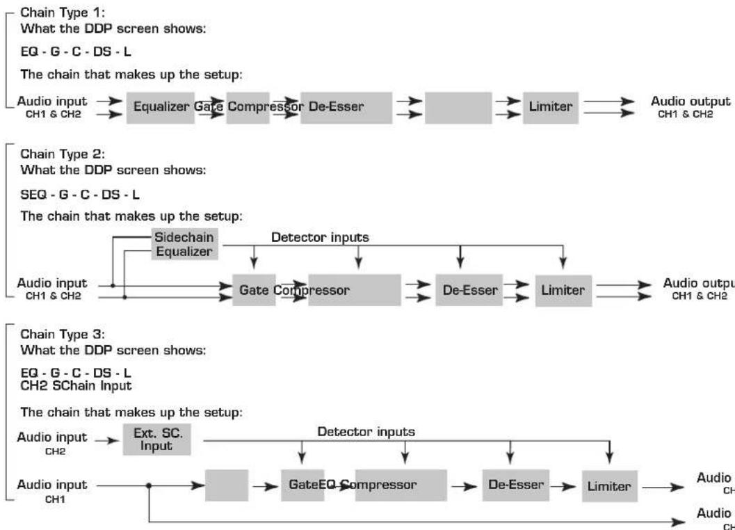
There are three different linked chain sequences built in to the DDP. From these sequences you can build your own unique chains in order to fit your needs. They are listed below.
LINKED chains
The following chain types are available in any Linked Setups:
flowchart
graph LR
    subgraph Chain Type 1
        A["Audio input CH1 & CH2"] --> B["Equalizer"]
        B --> C["Gate Compressor"]
        C --> D["De-Esser"]
        D --> E["Limiter"]
        E --> F["Audio output CH1 & CH2"]
    end

    subgraph Chain Type 2
        G["Audio input CH1 & CH2"] --> H["Sidechain Equalizer"]
        H --> I["Gate Compressor"]
        I --> J["De-Esser"]
        J --> K["Limiter"]
        K --> L["Audio output CH1 & CH2"]
    end

    subgraph Chain Type 3
        M["Audio input CH2"] --> N["Ext. SC. Input"]
        N --> O["GateEQ Compressor"]
        O --> P["De-Esser"]
        P --> Q["Limiter"]
        Q --> R["Audio output CH1 & CH2"]
    end

    A --> B --> C --> D --> E --> F --> L --> M --> N --> O --> P --> Q --> R
    style Chain Type 1 fill:#f9f,stroke:#333
    style Chain Type 2 fill:#f9f,stroke:#333
    style Chain Type 3 fill:#f9f,stroke:#333
Figure 11: Available linked chains
flowchart
graph LR
    A["analog input jacks"] --> B["Channel One"]
    B --> C["CH1 digital input meter"]
    B --> D["CH2 digital output meter"]
    C --> E["DSP (Software - based) Operations"]
    D --> E
    E --> F["Ch1 digital output meter"]
    F --> G["Channel One"]
    G --> H["analog output jacks"]
    I["Chanc. 2 OUT"] --> J["Dynamics Processor"]
    K["Chanc. 2 IN"] --> J
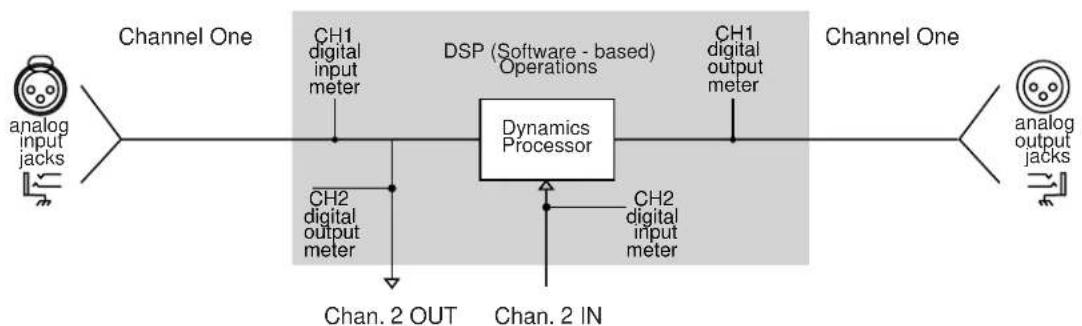
Figure 12: DDP Linked Chain Type #3 Audio Connections
External Sidechain and the Digital Meters
The DDP's external sidechain path offers you the ability to use other processors in the sidechain path. The digital meters give you comprehensive feedback for ease of setup. Note in figure 12 above where the metering points are for the digital meters when the DDP is in external sidechain mode. The Channel One meters will be showing signal whether or not there is signal being passed through the sidechain. The Channel Two meters also show on the way to the sidechain device as well as coming back form the device. When you press the Bypass button in sidechain mode, both input meters will continue to operate, allowing you to see levels while bypassed.
Section 3: Setup / Basic Operation
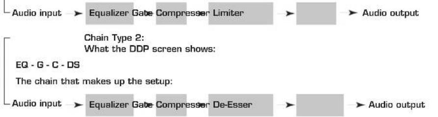
There are also six different mono chains available to any dual mono program on the DDP. Three have in-line 3-band parametric EQ and three have sidechain EQ. They are as follows:
MONO chains
The following chain types are available in any mono Setups:
Chain Type 1:
What the DDP screen shows:
EQ-G-C-L
The chain that makes up the setup:
flowchart
graph LR
    A["Audio input"] --> B["Equalizer Gate Compressor Limiter"]
    B --> C["Audio output"]
    D["EQ-G-C-DS"] --> E["Chain Type 2: What the DDP screen shows:"]
    F["The chain that makes up the setup:"] --> G["Audio input"]
    H["De-Esser"] --> I["Equalizer Gate Compressor Limiter"]
    I --> J["Audio output"]
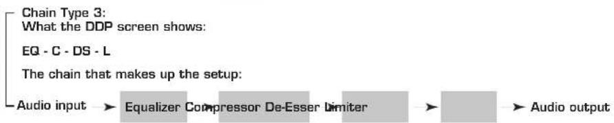
flowchart
graph LR
    A["Chain Type 3: What the DDP screen shows:"] --> B["EQ - C - DS - L"]
    B --> C["The chain that makes up the setup:"]
    C --> D["Audio input → Equalizer Compressor De-Esser Limiter"] --> E["Audio output"]

flowchart
graph LR
    A["Audio input"] --> B["Gate Compressor Limiter"]
    C["Sidechain Equalizer"] --> B
    D["Detector inputs"] --> B
    B --> E["Audio output"]

flowchart
graph LR
    A["Audio input"] --> B["Sidechain Equalizer"]
    B --> C["Gate Compressor"]
    C --> D["De-Esser"]
    D --> E["Audio output"]
    F["Detector inputs"] --> C
    G["Chain Type 5: What the DDP screen shows: SEQ - G - C - DS"] --> F

flowchart
graph TD
    A["Audio input Audio output"] --> B["Compressor De-5eser Limiter"]
    B --> C["Output"]
    D["Sidechain Equalizer"] --> E["Detector inputs"]
    E --> B
    style A fill:#f9f,stroke:#333
    style B fill:#ccc,stroke:#333
    style C fill:#ccc,stroke:#333
Figure 13: Available Mono Chains
Section 3: Setup / Basic Operation
From Program Mode (press the Program button), you can enter setup mode by pressing either the "CH 1" button or the "CH 2" button. Notice that when you do, several things happen on the screen:
- The reversed-text channel number (either "1" or "2") to the right of the program number will light, indicating the "active" channel. The other number will go out. (If you are working with a linked setup, both the "1" and "2" will light, as well as the word "link" between the two numbers.)

Setup mode in dual mono

Setup mode in linked mode
-
The first line of text says. "Ch 1 Setup". The second line of text indicates the setup's title.
-
The third line of text shows the elements of the setup's chain in their proper order.
-
The curve window shows text reading "FACTORY setup", or "USER setup".
-
Using the Data Wheel, scroll through the available setups. You should recognize these from the previous pages. The chain that is displayed in the window is the one that is active. All the DDP's factory setup names are listed in Appendix #1, page 24.
Viewing Elements of a Chain
Individual elements of every setup chain may be viewed and their parameters manipulated. We have provided you with a full slate of parameters for each element. They are described in section 4.
Linked Programs
Select a linked program. If you want to edit the parameters of a linked setup, simply press the function button that corresponds to the element you want to edit. For example, if you wish to edit the parameters of the compressor, just press the compressor button. It will light up, as will the compressor icon to the right of the program number on the DDP's display, indicating that you are ready to edit the parameters of the compressor. As you do so, the STORE button will light indicating that you have made changes to the parameters and must store them in order for them to be saved for later use.
Dual-Mono Programs
Using a dual mono program number, (one without the "LINK" icon lit between the "CH1" and "CH2" icons) select the element you wish to edit by simply pressing the corresponding function button, like the Compressor button, for example. Note that as you do, the icon corresponding to the element lights up beside the program number, the function button lights up, and the top line of text shows the element being edited. Also note that either the CH1 or CH2 icon is lit. It lets you know which channel's compressor you are editing, for example. To edit the other channel's compressor, simply press the Compressor button again. Everything stays the same except for the CH1 icon has turned off and the CH2 is lit. You can switch between channels in this way from any chain element. If the CH1 and CH2 setups are different from each other, trying to switch to an element not present in the other setup will result in nothing happening at all. You will remain in the channel that contains the element you selected.
Section 4: Editing / Saving / Recalling Programs
THE STORE BUTTON
Whenever a parameter has been changed, the Store button will light, prompting you that there have been changes made to the setup. If you want to keep the changes, you must store the new setup. You may choose to rename and save the setup in the setup library. Or you may choose to abandon your changes when you leave the program for another one. Refer to the end of this section on page 20 for complete instructions for saving setups.
MOVING AROUND
Since there are only three parameters viewed at any one time it is necessary to have multiple "pages" of parameters. The gate has three pages of parameters. For example, on the first page of the gate section there is: Gate ON /OFF, Threshold, and Ratio. The next page can be seen by pressing the NEXT PAGE / PREV PAGE buttons. The number of the current page is shown to the right of the program number and under the chain identifying numbers in reversed-text. The parameters on page 2 are: Attack, Hold and Release. The third and last page has Transient Capture Mode™ On / Off, and TCM Time. For a full explanation of Transient Capture Mode, see Section 6.
The SELECT button moves the cursor between the three lines of parameters on each page, and the DATA wheel changes the parameter that is selected. Note that in order for any changes to be heard, the element must first be in the "on" position.
EDITING GATES
Parameters of the Gate
The parameters included on the DDP for gating operations are as follows:

bar
| Parameter | Value | | :--- | :--- | | Input | -6 | | Output | +6 | | Gate Link | 18 | | Parameter 1 | -2 | | Gate ON Threshold | -9 | | Parameter 2 | -12 | | Parameter 3 Ratio | -40 | | Gain Reduction | 0 | | dB | -15 | | threshold knee | -60 | | gate ratio | -75 | | (Data not extractable as discrete values; image contains only a grid of bars and a line graph) | (Data not extractable as discrete values; line graph is continuous).Figure 14: Gate parameters and curve
Off/on: This is a bypass for the gate section. Turning it to “off” deactivates the minus (-) section of the threshold meter, and the plus (+) sign is darkened, indicating that the gate is passing signal through, regardless of the other gate settings.
Threshold range from -75dB to 0dB: The threshold range goes from -75dB to 0dB. With the threshold set towards -75dB, it takes less signal level to "open" the gate. A setting closer to 0dB requires more amplitude or level to open the gate. As you move the threshold around, notice the behavior of the curve window. The "knee" of the threshold moves up and down according to your setting. Moving the threshold "up" means it takes a louder signal to exceed the threshold.
Ratio from 1:1 to 1:∞: The gate ratio sets the amount of gain reduction. (With a lower ratio setting, the gain reduction is lower than a higher ratio.) For mild gating effects, or downward expansion, set the ratio around 1:2, or for more extreme effects set it to 1:∞. For example, a setting of 1:2 means that for every 1dB that the signal is below the threshold (say, 4, for example), the gate imposes 2dB of gain reduction on the signal (for a total of 8dB in this example). As you move the ratio control around, notice the action of the curve in the curve window.
Section 4: Editing / Saving / Recalling Programs
Attack control from 0.1ms to 200ms: As the signal reaches the threshold area, the Attack control sets the speed at which the gate opens. Use very fast attack times to catch the fronts of transient signals.
Hold from 0ms to 500ms: The Hold control sets the amount of time the gate is held open after the signal passes below the threshold point.
Release from 360dB/sec to 5dB/sec: Release sets the speed at which the gate "closes" when the end of the Hold time is reached.
TCM ^™ Off/on: Transient Capture Mode is the method by which the gate is able to catch the very beginnings of fast transient signals. Using TCM ^™ results in a smoother sounding signal, because of the increased ability to use slightly less aggressive settings and still achieve the desired effects in gating, compression, and limiting.
TCM time from 0μs to 3ms: TCM delay time is variable in the length of time it delays the audio signal, allowing the detectors to begin to react to the signal. For a complete explanation of TCM™ Transient Capture Mode™, see section 6.
EDITING COMPRESSORS
Parameters of the Compressor
The parameters included on the DDP for compression operations are as follows:

Figure 15: Compressor parameters and curve
Off/on: As with the gate, the compressor section must be turned on. The curve window will show the compression threshold, as well as the ratio and gain levels.
dbx OverEasy® off, knees 1-10: Activating the OverEasy® threshold characteristic softens the compression knee, making the transition between uncompressed and compressed signal as seamless as possible. In addition to having the on/off setting, you may choose varying knee slopes with the VariKnee™ variable knee algorithm (see figure below). Selecting knee #1 activates the curve next to the hard knee curve, #2 selects the next softer knee, etc., up to knee #10, which is the softest knee.

line
| Output | Knee #1 - Small OverEasy range | Knee #10 - Larger OverEasy range | | ------ | ------------------------------ | -------------------------------- | | -60 | -60 | -60 | | -50 | -50 | -50 | | -40 | -40 | -40 | | -30 | -30 | -30 | | -20 | -20 | -20 | | -10 | -10 | -10 | | 0 | 0 | 0 |Figure 16: OverEasy® VariKnee curves
Section 4: Editing / Saving / Recalling Programs
Auto mode off/on: Activating Auto mode disables the Attack, Hold and Release controls, triggering a message to that effect in the curve window. Attack and release settings become fully program-dependent, and manual changes in the settings do not have any effect on the audio signal or the response of the compressor. Auto mode is especially effective on signals such as vocals or other highly dynamic signals. Most factory setups use Auto mode because of its ability to perform smooth compression under widely varying circumstances.
When Auto Mode is activated, the Attack, Hold and Release controls are program-dependent and are not affected by your manual settings.
Threshold range from -60dB to +4dB: Setting the threshold is the same on the compressor as it is on the gate or limiter. There is a visual representation of the threshold on the curve window, and as you edit the parameter, you will see motion up or down on the curve window, allowing much greater understanding of the effects of each parameter on the entire compression algorithm.
Ratio from 1:1 through ∞:1: As the signal passes through the threshold region, it begins to be compressed at the rate set with the ratio setting. It is expressed in a ratio for ease of use, for example, with a ratio setting of 4:1, the signal would have to increase by 4dB in input to increase the output by 1dB. With the wide-ranging control on the DDP, it is possible to achieve very smooth, transparent compression as well as heavy, in-your-face compression effects.
Gain from -20dB to +20dB: When a signal is compressed, by definition some of its gain is taken away. It therefore becomes necessary to boost the now-compressed signal back up to a useable level. As you make this adjustment you can see the effect in the curve window. The compressed signal is now more dynamically controlled and can be boosted to a level that was not possible before it was compressed.
Attack control from 0.1ms to 200ms: As the signal exceeds the threshold, the speed at which the compressor begins to react is set by the Attack control. Its range is from very fast to somewhat slow, allowing you to have all the control you want. The Attack control is active when not in Auto mode (see Auto mode above).
Hold from 0ms to 500ms: Hold sets the minimum gain reduction amount for a determined amount of time, after the signal passes below the threshold. If the signal goes back above the threshold, the hold time is “restarted” and will hold the compressor at that amount of gain reduction for the set time, after the signal once again moves below the threshold. The Hold control is active when not in Auto mode (see Auto mode above).
Release from 360dB/sec to 5dB/sec: The release control sets the speed at which the signal is returned to the normal signal after it has gone below the threshold, and the Hold time has been exceeded. The Release control is active when not in Auto mode (see Auto mode above).
Section 4: Editing / Saving / Recalling Programs
EDITING LIMITERS
Parameters of the Limiter
The parameters included on the DDP for limiting operations are as follows:

bar
| Parameter | Value | | :--- | :--- | | Input | -6 | | Output | +6 | | Limiter | -4 | | Parameter 1 Limiter GON Threshold -5 | -5 | | Parameter 2 Limiter threshold | -5 | Gain Reduction: 0 (limiter output level) → -15 (G-+), -30 (G-+), -45 (G-+), -60 (G-+), -75 (G-+), -90 (G-+), -105 (G-+), -15 (G-+).Figure 17: Limiter parameters and curve
Off/on: Again, the limiter must be turned on to be able to change the parameters and affect the signal. The curve window shows the threshold point of the limiter.
Threshold control from -60dB to +4dB: As you move the threshold of the limiter up and down, you see the output level of the DDP move in relation to the setting. This means that the limiter of the DDP sets the absolute output level for the unit. Remember that very fast transient signals can occasionally “sneak” past the threshold control of any limiter. If you wish catch every single transient, set the TCM to a longer delay time, allowing the DDP to begin to react to a transient signal faster. (For complete information on the TCM™ Transient Capture Mode controls, refer to the gate section on page 14 and 15, as well as appendix #1) Also note that the digital meters show when even 1 sample gets through the threshold. this can be disconcerting, given the fact that it appears that much more signal actually gets through the threshold. Also, it is possible to set the threshold of the limiter below the threshold of the compressor, causing all of the gain reduction to happen in the limiter, and none to happen in the compressor. As you do this, you will notice that the curve window displays exactly what the threshold level is set to, even to the point of “overwriting” the compression settings. Move the threshold level of the limiter up and down to see how this effects the composite signal. Limiting takes place after the compressor's gain control setting
Attack control from 0.1ms to 200ms: The attack control sets the speed at which the signal is limited as it crosses over the threshold into the limiting region.
Release from 360dB/sec to 5dB/sec: The release control sets the speed of release of the signal as it goes below the threshold, out of the limiting region, and is returned to its normal, unprocessed waveform.
Section 4: Editing / Saving / Recalling Programs
EDITING DE-ESSERS
Parameters of the De-Esser
The parameters included on the DDP for De-Essing operations are as follows:

bar
| Parameter | Value | | :--- | :--- | | Input | +6 | | Output | +6 | | Parameter 1 | -2 | | De-esserDOFF | -12 | | Parameter 2 | -15 | | Freq | -20 | | Parameter 3 | -25 | | Amount | -30 | | Gain Reduction | 0 | | Gain Reduction | 1 | | Gain Reduction | 2 | | Gain Reduction | 3 | | Gain Reduction | 4 | | Gain Reduction | 5 | | Gain Reduction | 6 | | Gain Reduction | 7 | | Gain Reduction | 8 | | Gain Reduction | 9 | | Gain Reduction | 10 | | Gain Reduction | 11 | | Gain Reduction | 12 | | Gain Reduction | 13 | | Gain Reduction | 14 | | Gain Reduction | 15 | | Gain Reduction | 16 | | Gain Reduction | 17 | | Gain Reduction | 18 | | Gain Reduction | 19 | | Gain Reduction | 20 | | Gain Reduction | 21 | | Gain Reduction | 22 | | Gain Reduction | 23 | | Gain Reduction | 24 | | Gain Reduction | 25 | | Gain Reduction | 26 | | Gain Reduction | 27 | | Gain Reduction | 28 | | Gain Reduction | 29 | | Gain Reduction | 30 | | Gain Reduction | 31 | | Gain Reduction | 32 | | Gain Reduction | 33 | | Gain Reduction | 34 | | Gain Reduction | 35 | | Gain Reduction | 36 | | Gain Reduction | 37 | | Gain Reduction | 38 | | Gain Reduction | 39 | | Gain Reduction | 40 | | Gain Reduction | -24 | | Gain Reduction | -18 | | Gain Reduction | -12 | | Gain Reduction | -6 | | Gain Reduction | -0 | | Gain Reduction | +6D+| | Gain Reduction | -6 | | Gain Reduction | -12 -6 | 800Hz | 8k: 800Hz = 8k: 8k = 8k: 8k = 8k = 8k = 8k = 8k = 8k = 8k = 8k = 8k = 8k = 8k = 8k = 8k = 8k = 8k = 8k = 8k = 8k = 8k = 8k = 8k = 8k = 8k = 8k = 8k = 8k= 8k= 8k= 8k= 8k= 8k= 8k= 8k= 8k= 8k= 8k= 8k= 8k= 8k= 8k= 8k= 8k= 8k= 8k= 8k= 8k= 8k= 8k= 8k= 8k= 8kFrequency at which de-essing begins to occur
Figure 18: De-Esser parameters and curve
Off/on: Same thing as all the others. When you are not using the de-esser, it should be turned off.
Frequency control from 800Hz to 8kHz: The Frequency control is much like an audio threshold point as it relates to frequency, rather than amplitude or level. As you scroll through the control area you will see the curve move in accordance to your settings. You are setting the frequency point at which de-essing will begin to occur. For the email voice a good starting point is in the 5-8kHz range, and for males the range is a little lower, about 3-6kHz.
Amount from 0% to 100%: The Amount control varies the amount of de-essing. For light de-essing set it low, and for a heavier effect, set it higher.
EDITING THE SIDECHAIN EQ AND THE IN-LINE EQ
Parameters of the EQ
The parameters included on the DDP for EQ operations are as follows:

bar
| Parameter | Gain Reduction | | :--- | :--- | | EQ | 1 | | EQ | 2 | | EQ | 3 | | EQ | 4 | | EQ | 6 | | EQ | 9 | | EQ | 12 | | EQ | 15 | | EQ | 18 | | EQ | 21 | | EQ | 25 | | EQ | -6 | | EQ | -12 | | TSE | 30 | | TSE | 35 | | TSE | 40 | The chart displays 'Gain Reduction' as a vertical bar chart with a scale bar on the right. The input and output values are shown above each bar. The x-axis represents frequency in Hz (25Hz to 20K), and the y-axis represents gain reduction. The labels 'Input', 'Output', 'EQ' indicate the parameter combinations. The 'GON' label is centered near the center of the plot. The 'NORMAL' label is also centered near the center but lacks explicit numerical labels. The 'Gain Reduction' axis is labeled 'Gain Reduction'.Figure 19: EQ parameters and curve
Off/on: Like any other element, the EQ must be turned on.
Monitor off/on: If you are using a program number that has the sidechain functionality enabled, the next parameter you see will be MONITOR. The sidechain monitor lets you hear the signal you are using in the sidechain path, as opposed to the signal you are using for the audio ins and outs. This can be useful for identifying and centering on specific frequencies.
TSE mode: Dark, Warm, None, Light, Bright: There are five TSE ^™ Tape Saturation Emulation settings in the DDP. TSE ^™ is tied to the TYPE IV ^™ Conversion process, and allows you to add definition to your recordings in pleasing amounts of your choosing. Because TSE ^™ is related to the analog to digital conversion process, its settings are inactive while processing a digital source. (See Appendix 1.)
Section 4: Editing / Saving / Recalling Programs
Bands 1, 2, and 3: The EQ is a three band parametric which allows adjustments of frequency center, Q, and level.
Frequency Center from 25Hz to 20kHz: You can choose a center frequency from 25Hz to 20kHz all all three bands of the EQ.
Q from .25 to 16: "Q" is a setting that measures the width of the effect beyond the center frequency. For example, a Q of 8 or 16 will produce a very sharply pointed EQ setting, effecting very few frequencies outside of the selected frequency center. A Q of .5 or 1 produces a very wide range of effect beyond the center frequency. The effect is a broad, smoother EQ setting.
MORE ABOUT SIDECHAIN EQ
The sidechain functions are convenient in many applications, such as broadcast engineering, where engineers are asked to provide "ducking" functions, as well as de-essing. Frequency-specific and sustain-related compression are also possible with the use of the sidechain functions of the DDP. See figure below for an illustration of the relationship of the sidechain path to the DDP's metering points.
It is possible to separate certain vocals and instruments from a mix using frequency-weighted compression. With the 3-band parametric EQ in the sidechain path, the equalization settings do not shift the timbre or frequency response of the audio signal. They merely alter the threshold response of the processing section of the DDP on a frequency-weighted basis.
With this arrangement, raising certain frequencies on the equalizer causes them to be suppressed in the audio signal. A relatively high threshold setting can allow normal sounds to be unaffected while solo and very loud sounds are held back. (Of course, when compression does occur, the level of the entire program is affected.) Depending on the threshold setting, lower level fundamentals or harmonics will not cause compression.
During the recording of cymbals and tom-toms, a compressor with an equalizer in the sidechain path can help prevent tape saturation. The equalizer can be adjusted for boost with a peak of about 5kHz, causing the cymbal to be compressed on a very loud crash, stopping tape saturation at high frequencies, where there is less headroom. However, gentle tapping of a drumstick or brushing of the cymbal will not be held back. Assuming the tom-tom is a lower frequency instrument and can be better tolerated by the tape, it has less need for compression. The equalization in the sidechain circuit means that the compressor is not triggered as readily by a loud tom-tom beat as by an equally loud cymbal crash.
The converse of the above EQ technique may be used: dipping the equalizer bands causes any sound with dominant energy in the affected register to pull the level up because the DDP will detect a need for less compression.
To apply de-essing to vocals without using the De-Esser element, use the parametric equalizer in the sidechain circuit and set it for high frequency boost in the specific frequency range where the vocal hiss or lisp occurs (generally in the 4-6kHz region). This pre-emphasizes the already hissy vocal input to the detector. Used in conjunction with a moderate to high threshold and compression ratio, this arrangement greatly attenuates the essing without affecting the basic sound quality or balance of the voice. While it is true that all frequencies are lowered in level when the compressor is triggered, generally the sss sound occurs alone, before or after the dominant tone in the voice. In the DDP use the factory setup called "De-ess vocal" for this effect.
To increase the sustain of a musical instrument (e.g., a guitar or bass), use the sidechain circuit and boost the EQ in the dominant frequency range of the instrument, along with a fairly low threshold and a moderate compression ratio.
Section 4: Editing / Saving / Recalling Programs
The sidechain path may also be used to reduce the effects of low frequencies on the compressor. Using the EQ to de-emphasize low frequencies allows the detectors of the gate, compressor, and limiter elements to react only to the more musical parts of the audio signal. This method greatly reduces the “pumping and breathing” that can occur in compressors.
The in-line 3-band parametric EQ works in the same way as the sidechain EQ. It is a 3-band parametric EQ that has variable Q and a +/-12dB boost or cut ability in each of the 3 bands
CHANGING CHAIN TYPES
Users who wish to configure the DDP "from the ground up" may do so. While in program mode and on any program number you may press, hold, and release the Program button to enter the CONFIG SETUP mode. Doing so from a stereo linked program number takes you to a screen that says "Config Setup" in the top text line under the program number. In the second line of text you will see the cursor and the current chain in any stereo setup. You can scroll between them and choose one of them for your setup by pressing the store button.
NOTE: BEFORE ENTERING CONFIG SETUP ALWAYS SET AUTOLOAD TO ON.
If you are using a dual mono program, the screen will allow you to choose two different setups from among the 6 chain choices. Once you have chosen the setups, you will need to store the new program you have created. You may save your work at any time. If you like to live dangerously, just save before you finish the session, or save more often, it's up to you. The store LED will light as you scroll to new chains, indicating that you must press store in order to make the current selection active in the program you are in. After you have pressed store, press program again and you will return to program mode. You will need to setup each element of the processing chain. Note that when you choose to create a setup from the user config menu, all the parameters of the chain are turned to the nominal or off position, depending on the parameter.
SAVING PROGRAMS AND SETUPS
Saving a program
The most important part of saving your processing library is realizing the following:
PARAMETERS ARE ASSOCIATED ONLY WITH SETUPS, NOT WITH PROGRAMS
Saving a program is done by following these steps:
- While in Program mode, press the Store button. The screen looks something like this.
- You have the choice of saving the Program, or Saving the setup. Choose the first option by simply pressing the Store button while the cursor is in front of the word "Prog".

Figure 20: Store program
- As you do this, the screen goes to the next save page, asking you to name the new program. The curve window shows instructions.
Section 4: Editing / Saving / Recalling Programs
- When you have named the new program, press store again. the screen bumps to the next save screen, asking you to select a program for the DDP to erase and write the new program over. Note that you can only access programs 1-50 in this screen, as that is the only area where you can write new programs over old ones. Select the number where you want to write the new program and press store once more. Momentarily the screen will say "Done!" in the first line of text.
You have now saved a program consisting of two setups or one linked setup.
NOTE: YOU HAVE NOT SAVED ANY PARAMETERS AT THIS POINT.
For example, if you chose to save Program ≠40, with setups "Slap Bass" and "Thick Kick", the information you have saved is the following:
Program #40
uses: setup "Slap Bass"
and: setup "Thick Kick"
Setups contain parameters. In order to save parameter settings you must save the setup.
Saving a setup
Saving a setup can be done by following these steps:
- After you have edited your setups to your liking press the Store button. The screen will look like figure 21 below. Move the cursor down to either CH 1 Setup, or CH 2 Setup, if you have been editing a dual mono program. If you have been working with a linked program, your second choice will be "Link Setup". Make your selection by pressing the Store button again. Remember that there is room in the DDP to store 100 linked setups and 100 mono setups, in addition to the factory setups.
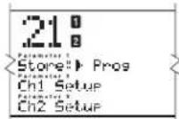
Figure 21: Store setup
-
Like above you are asked to name your setup. Again, there are instructions for you in the curve window. Press Store when you are done.
-
You now must choose what you want to do with the setup you are going to save. You have two choices: you may write over another setup, or you may make a new one.
Replace Old:
-
To replace an old setup, move the cursor to the Replace Old choice and press Store. You are given a choice of which setup to replace. Using the Data Wheel scroll to the name of the setup you wish to replace with your new setup. Press Store.
-
After a brief pause, the screen will display the text, "Done!", and you have saved a setup over the old setup that you chose. If you wish to save your setup to a new spot without erasing any other setups follow these instructions:
Section 4: Editing / Saving / Recalling Programs
Store New:
-
To store a new setup, choose Store New after pressing the store button. Again, you must name your new setup. After you are done, press Store once again. You now must choose a place for the new setup to be placed in the setup library. The name of your new setup is displayed on the middle line of text (the "Parameter 2" spot).
-
Use the Data Wheel to scroll to the place where you want to the new setup added. As you scroll, notice the names of the setups already in the library scrolling by on text lines 1 and 3 (parameter 1 and parameter 3). This indicates that you are placing your new setup between the two setups displayed above and below your new one. The DDP "makes room" for your setup, no matter where you want to place it.
-
Pressing Store once more saves the setup in the spot you chose, and after a brief pause, the screen display the "Done!" line and you have saved a setup, complete with all parameters, ready to use next time.
Notice that as you write over an old setup, all other programs that recall that setup will now recall the newly saved setup.
Section 5: Utility Functions
UTILITIES
The Utilities menu is accessed at any time, via the Utility button. The utilities menu is the same as the other menus of the DDP. Once in the utility area, the LED will light on the Utility button, indicating the selection. Different menu selections are shown in the three lines of text below the program number. When you are using the utilities menu, the DDP continues to pass signal, and displays the current program number without interruption. Following is a brief explanation of the different utilities and their parameters:
Contrast
The contrast selection is always shown on the first line in the "Parameter 1" position, and adjusts the displays visibility.
Sample Rate
The next utility is Sample Rate. This utility changes the output sample rate. The choices are: 44.1kHz or 48kHz. As technology advances, future software and hardware updates will include other options. The DDP is currently shipped with the 48kHz choice as the default. However, in “digital Input” mode, the sample rate is “locked” to the sample rate of the digital input signal. To help you remember, the display window will show text to this effect.
AutoLoad
With the AutoLoad feature, you may choose whether the DDP will immediately load the program number on the display, or whether you must be prompted to load the current number into the audio path. With AutoLoad in the ON position, the DDP automatically loads the current program into the audio path without a prompt. While this can be convenient, care should be taken, because if you move the data wheel while in program mode AFTER you have changed parameters in the current program, the program number will be changed and the changes will be lost as the DDP moves to the next program number and loads it into the audio path automatically. In addition, if the DDP is used in a live sound situation, the ramifications could be disastrous if someone bumped the data wheel while signal was being passed through the DDP. With AutoLoad in the OFF position, you can scroll to other program numbers without affecting the sound being passed through the DDP. As you make changes to a program, then move the data wheel to another program number, the Load button will flash, telling you that you are in a program number other than the one you have had loaded into the audio path. One press of the LOAD button loads the currently displayed program number into the audio path, and dumps the previous program number from the audio path. AutoLoad mode is best used when changing Program numbers and changing parameters within the given setups. AutoLoad should be “OFF” when you want to change setups within any specific Program number.
NOTE: BEFORE ENTERING CONFIG SETUP (PAGE 20) ALWAYS SET AUTOLOAD TO ON.
As you move from the program level in another program to the setup level, the Load button begins to blink, indicating that you are looking at processing chains other than those that are currently loaded into the audio path. As you return to the program level, and move back to the original program number, the Load button turns off, as there is no need to "re-load" the current program, because it has already been loaded, and is in fact the current program number in the audio path.
Input Mode
This is where you will select the input mode of the DDP. If you have the optional Digital I/O card installed in your DDP, this page refers to setting the input format of the DDP. You can set the input and output independently to either AES/EBU or S/PDIF formats. The analog outputs still operate regardless of the settings in this utility. If you see an "Input Error" message, make sure that the appropriate cables are hooked up on the back of the DDP and that your settings reflect your cable setup.
Section 5: Utility Functions
Output Mode
This is where you will select the digital output mode of the DDP. If you have the optional Digital I/O card installed in your DDP, this page refers to setting the output format of the optional card. You can set the input and output independently to either AES/EBU or S/PDIF formats. The analog outputs still operate regardless of the settings in this utility. If you see an "Input Error" message, make sure that the appropriate cables are hooked up on the back of the DDP and that your settings reflect your cable setup.
Digital Input Level Controls
The next utility is digital input level controls. Note that when you are using the analog inputs of the DDP, this utility does not change the level of the signal. When the input is set to AES/EBU or S/PDIF, you may adjust the level of both the left (channel 1) and right (channel 2) channels of the digital signal. This function is helpful for balancing and fine tuning the mix of the two channels of digital signal.
MIDI / SysEx
The next set of utilities is MIDI based functionality. In the first parameter line, the DDP displays "MIDI Ch". This may be set for channels 1-16, off and OMNI, which is the typical implementation. Communicating with the DDP through the MIDI language is as easy as in any other MIDI unit: program changes as well as parameter changes may be activated through the MIDI ports. In addition, the DDP allows you to send and receive "system exclusive" data and commands on channels other than the MIDI channels, allowing you to perform such complex maneuvers as complete system program dumps and reloads, system setups, and output configurations. These are the SysEx channels. SysEx control is twofold: SysEx channels range from 0-16 and OMNI.
Other MIDI features follow on utility pages 3 through 7. Page 3 of the Utility menu allows you to set the MIDI and SysEx channels for the DDP. Page 4 allows you to perform MIDI merging. CCs are another good and easy way of communicating with the DDP. For a complete guide to the full functionality of the MIDI, CC and SysEx implementation, see section 6. Utility pages 5 and 6 work together and allow you to transfer setups between DDPs as well as backup to computer, if you have a MIDI interface system. Page 5 will receive any setup name as any other, and page 6 will let you send setups the same way.
You may also send the entire contents of the DDP, including MIDI information, and parameter settings via Utility page 7. A bulk dump sends the entire set of programs and setups via the MIDI port.
For complete MIDI / SysEx / CC information see Appendix #4.
A / D Calibration
The last page of utilities is a calibration section for the analog to digital convertor chips. You will notice a set of more complete instructions displayed in the curve window area. To calibrate the converters, first turn the input controls of the DDP fully counter-clockwise (-∞) or off. Calibrations performed with these controls open at all could result in inaccurate calibrations, giving the DDP poor processing performance. After the input controls have been turned to the OFF position, press the STORE button. If the calibration is not successful, the following text will appear in the third parameter area: "A/D CAL FAIL!" If this happens you should turn the DDP off then back on. If the problem persists, call dbx technical support at 1-801-568-7660 for assistance.
Section 6: Appendices
APPENDIX 1: MISC. INFORMATION
Hard Reset
From time to time you may encounter a situation which locks up the DDP's software. Usually this is due to operator error. Which means you asked the DDP to do something we did not anticipate in the implementation of the software, or something else has locked up the DDP. It may be necessary to do a "Hard Reset" Perform this only when there is no other option, either by turning off and then on, or moving to another area in the software and then back again.
To do a Hard Reset:
- Turn the DDP off.
- Hold down the Bypass and Store buttons
- Turn on the DDP.
- When the asterisk appears in the Parameter 1 line, press Next Page button.
Change Default Startup Program
The DDP turns on in "Program Mode" and is ready to use without any other keystrokes being necessary. The DDP "remembers" the last program number used, and stores that program number as the default startup program number. Occasionally you may wish to manually manipulate this setting. Do so by holding down the Program button while turning on the DDP.
Front Panel Lockout
The DDP's controls may also be locked, effectively disabling the front panel. Holding the Utility button while turning on the DDP displays an instruction screen telling you to press the Prev Page button to toggle the locked status. When locked, the program name line flashes between the name of the program and the text, "DDP Locked!" Unlocking the DDP controls is accomplished the same way. Note that when in locked mode the DDP can still be controlled via MIDI operations, as well as SysEx commands and CC information.
Type IV™ Conversion System
We have included the Type IV ^™ Conversion Process as the primary method of analog to digital conversion on the DDP. When the analog inputs are selected, the TYPE IV ^™ icon to the right of the program number lights up and the TYPE IV ^™ process takes over as the means of converting the analog signal to a digital signal. This means that you may hit +6dB on the digital input meters for the DDP and not hear any audible distortion. This behavior is not unlike an analog tape machine. In conjunction with TSE ^™ Tape Saturation Emulation, the essence of the analog signal is captured to the digital medium in a way that preserves the color and emulates the behavior of an analog tape recording. This process results in a digital signal that is more pleasing to the ear, and offers a more musical, useable signal for the DDP to process, resulting in master-quality sound output, whether digital or analog.
TSE™ - Tape Saturation Emulation
Analog tape has always had a specific "sound". In fact different brands of magnetic tape have their own peculiar sound or "color". The color is most apparent when you drive the tape hard, almost to saturation. Conversely, digital signals have almost no "color". If you drive a digital signal to saturation, all you get is an ugly, unuseable "digital over" sound, much like fingernails on a blackboard. As a result, the sound, while crystal clear, can have a sterile or crisp sound. It is this crispness that has been to downfall of digital signals. Tape Saturation Emulation™ is a process of giving a digital signal an analog-type sound or color, making it more pleasing to the ear. On the DDP you can drive the input past the zero mark without risking the dreaded digital "over". Instead you get a pleasant saturation that is modeled after the sound of analog tape being saturated with signal. the controls for TSE™ are in the EQ section, and are global in effect. There are five different settings for TSE: Dark, Warm, Normal, Bright and Brighter. Each emulates an analog signal's "color" and is very unique. Their names reflect their characteristics.
The controls for TSE are always active. If you do not want any coloration added to your signal, simply set the controls to "Normal".
Section 6: Appendices
TCM™ - Transient Capture Mode
Transient Capture Mode ^™ , or TCM ^™ works on the principle of delaying the audio signal up to 30μs, and letting an unheard “control” signal begin to activate the response of the VCA. The overall result is the perception of a very fast moving compressor, able to catch the front of almost any transient signal, but not delaying the audio signal enough to produce any phase correlation errors. In the DDP, you may vary the delay, in the form of a TCM delay control, with a range from 0μs (microseconds (μs) are measurement units in 1000ths of a second) to 3ms. While this is not enough delay to cause phasing errors, it is enough to give the device time to start to react before the signal arrives at the point of processing.
The controls for the TCM section are in the Gate parameter area. While the effect is global, the gate must be turned on in order for the TCM module to work. If you want to use the TCM functions without the gate, simply turn the gate on and set the ratio to 1:1 and the threshold to -75dB. This effectively turns the gate on, but leaves it wide open, no matter what signal is presented at the threshold.
The resulting implementation in the DDP allows you to vary the amount of delay, based on the transient characteristics of the signal being processed. The signal sounds smoother and easier for the DDP to process in the compressor, limiter, and de-esser functions.
Section 6: Appendices
APPENDIX 2: FACTORY SETUP LISTING
Factory Setup Listing
Following is a complete listing of the factory designed setups. While this is not meant to be an exhaustive list of applications, it is meant to be a good starting off point for you to be creative in designing custom setups for you own needs. Notice the first three setups are factory default stereo setups that allow you to make a setup completely from scratch. Do you recognize the three different chain types from earlier in this manual? Further down the list, you will notice the six mono chain types as well.
Linked Setups
| St Def #1 | EQ-G-C-DS-L | ......“Default set-up with all values set to zero, for use when building a custom set-up from scratch.” |
| St Def #2 | SEQ-G-C-DS-L | ......“Default set-up with all values set to zero, for use when building a custom set-up from scratch.” |
| Ext Sch Def | EQ-G-C-DS-L | ......“Default set-up with all values set to zero, for use when building a custom set-up from scratch. Note: This is a mono set-up on channel 1 with channel two acting as the sidechain key.” |
| Light Mix EQ-G-C-DS-L | ......Very light compression and sweetening. | |
| Over Heavy EQ-G-C-DS-L | ......Heavy Compression with a light feel. | |
| Too Loud! SEQ-G-C-DS-L | ......Very heavy compression with lots of gain for that one louder setting. | |
| The Wave EQ-G-C-DS-L | ......Medium compression with heavy sweetening. | |
| Telephone EQ-G-C-DS-L | ......Medium compression with heavy EQ. | |
| Phat EQ-G-C-DS-L | ......Light compression with extra bass. | |
| Mr. Master EQ-G-C-DS-L | ......Light overeasy compression with just the right EQ for your DAT. | |
| Catz Meow EQ-G-C-DS-L | ......So light you will not even know it is on. | |
| SCh Bass EQ-G-C-DS-L | ......External sidechain for your bass. | |
| Thiknchunky SEQ-G-C-DS-L | ......Medium compression in the middle. | |
| St Drums | EQ-G-C-DS-L | ......“Medium compression, with EQ and gating to bring out the drums.” |
| St Vocal | EQ-G-C-DS-L | ......“Light compression, EQ and De-essing for those stereo background vocals.” |
| XL Bottom | EQ-G-C-DS-L | ......“Light compression with heavy EQ on the bottom.” |
| Hill & Dale | EQ-G-C-DS-L | ......“Light Compression, EQ and Gating, perfect for transferring from analog to digital.” |
| St F. Guitar | EQ-G-C-DS-L | ......Medium Compression with heavy Gating and a little bump in the bottom end. |
| St Piano | SEQ-G-C-DS-L | ......Very mild Compression and Gating with the Sidechain EQ to bring out the top and bottom of the piano and the room. |
| St Synth | EQ-G-C-DS-L | ......Light Compression with some gating and light EQ to clean up Synth tracks. |
| Tickle Mc | EQ-G-C-DS-L | ......Just a touch in all the right places. |
| Back Bacon EQ-G-C-DS-L | ......Light to medium compression with a little EQ to fatten up the mix. Eh. | |
| DJ Duck | EQ-G-C-DS-L | ......“A ducker, using the side chain to key the compressor.” |
| Cassette | EQ-G-C-DS-L | ......“Heavy compression with lots of Gating and EQ, to clean up a cassette vocal track.” |
Section 6: Appendices
Mono Setups
Default #1 EQ-G-Cmp-I. . . . "Default set-up with all values set to zero, for use when building a custom set-up from scratch."
Default #2 EQ-G-Cmp-DS . . "Default set-up with all values set to zero, for use when building a custom set-up from scratch."
Default #3 EQ-Cmp-DS-L . . . "Default set-up with all values set to zero, for use when building a custom set-up from scratch."
Default #4 SEQ-G-Cmp-L . . . "Default set-up with all values set to zero, for use when building a custom set-up from scratch."
Default #5 SEQ-G-Cmp-DS . "Default set-up with all values set to zero, for use when building a custom set-up from scratch."
Default #6 SEQ-Cmp-DS-L . "Default set-up with all values set to zero, for use when building a custom set-up from scratch."
Swift Kick EQ-G-Cmp-L . . . "Medium Compression, heavy Gating with a push in the bottom."
Fat Kick EQ-G-Cmp-L . . . Heavier Compression and EQ with lots of gating.
Solid Kick SEQ-G-Cmp-DS . .Heavy Compression and Gating with the bottom ringing.
Thick Kick SEQ-G-Cmp-L . . .Medium Compression on the mids and heavy gating on everything else.
Brite Snare EQ-G-Cmp-L . . . .Heavy Compression with a lot of gating and a dip at 400 Hz.
Rim Shot EQ-G-Cmp-L . . . Heavier Compression with lots of gating and a dip in the bottom.
Slam Snare SEQ-G-Cmp-L . . . "Medium Compression on the bottom with some gating, and a push at 315 Hz."
Tom's Toms EQ-G-Cmp-L . . . .Medium to heavy compression with some gating and EQ to accentuate the ring.
Tight Toms EQ-G-Cmp-L . . . "Heavy Compression with medium gating, a boost in the low mids, and the bottom rolled out."
Ringin Toms SEQ-G-Cmp-L . . . Medium Compression on the top and gating.
CongoCongas EQ-G-Cmp-L . . . .Light to medium compression with some gating and EQ to bring the top out.
Tambourine EQ-G-Cmp-L . . . .Medium compression with some gating and EQ to mellow out the top end.
Sh-shaker EQ-G-Cmp-L...Light compression and gating with the bottom rolled out.
Funk Bass EQ-G-Cmp-L . . . "A boost in the deep bass with a cut in the mid-bass, medium compression and a little gating."
Punchy Bass SEQ-G-Cmp-L . . .Sidechain EQ with light compression to enhance the low mids and a fair amount of gating.
Slap Bass EQ-G-Cmp-L...EQ with heavy compression and a lot of gating.
Rumble Bass EQ-Cmp-DS-L . . .Light overeasy compression with the top rolled out.
Martin's Gt EQ-G-Cmp-L . . . .Mild compression with a little EQ for your prized acoustic guitar.
F-Pick AcGt EQ-G-Cmp-L . . . Medium Compression with a little gating and EQ to keep your picking under control.
Folk Rock Gt SEQ-G-Cmp-L . . .Sidechain EQ combined with medium to heavy Compression to keep from feeding back.
Twang E Gtr EQ-G-Cmp-L . . . .Light Compression with a tiny boost in the top end to shine through.
2x12 Guitar EQ-G-Cmp-L . . . .Heavy Compression and gating with some sidechain EQ to keep the bottom punchy.
Monster Gtr EQ-G-Cmp-L . . . .Medium Compression with a big boost on the bottom.
FunkStompGt EQ-G-Cmp-L...Medium Compression with heavy gating and wild EQ.
Low Strings EQ-G-Cmp-L . . . .Light overeasy compression with a boost in the bottom end.
Hi Strings SEQ-G-Cmp-L . . .Light compression with a bump in the sidechain EQ to minimize harshness.
LushStrings EQ-G-Cmp-DS . .Very light compression with a push in the low end.
Horns O Luv EQ-G-Cmp-L . . . Medium Compression with some added top and bottom.
Mello Horns SEQ-G-Cmp-L . . .Sidechain EQ pushed in the upper mid with medium compression.
Horn Splat EQ-G-Cmp-L . . . .Medium to heavy overeasy compression with a push on the top.
Brite Horns SEQ-G-Cmp-L . . .Medium compression with a real gentle curve on the sidechain EQ.
7ft Grand EQ-G-Cmp-L . . . Very light overeasy compression with a little more bottom and top.
Upright Pno EQ-G-Cmp-L . . . .Medium compression with a small bump in the midrange.
Tight Voc EQ-Cmp-DS-L . . .Medium overeasy compression with some of the real low end rolled out.
Small Voc EQ-G-Cmp-DS . Medium compression and gating with the top and bottom rolled out.
De-ess Voc SEQ-Cmp-DS-L . .Medium Compression with the sidechain EQ bumped at 8KHz to control the sibilance.
Country Voc EQ-G-Cmp-L . . . .Light compression with a fair amount of top end.
Clear Voc EQ-G-Cmp-L . . . Medium to heavy Compression with the low end rolled out.
Ambient Voc EQ-Cmp-DS-L . . .Light Compression with the Sidechain EQ to accentuate the room.
Section 6: Appendices
APPENDIX 3: FACTORY PROGRAM LISTING
Factory Programs
The DDP comes with a set of factory designed programs that offer wide variety and flexibility for your dynamics control needs. They are located in programs 51-100. At the factory, we copied these programs into the user accessible area, programs 1-50. You may erase any or all of these programs at any time, and replace them with your own program numbers.
Program Ch 1 Set-up Ch 2 Set-up Program Ch 1 Set-up Ch 2 Set-up
- THE FINISHER ....Mr. Master ....<- linked
- COFFEEHOUSE .....F-Pick AcGtr.....Clear Voc
- AXE ATTACK......St E Guitar......<- linked
- BOOM....Fat Kick....Punchy Bass
- SAY WHAT? ....Phat....<- linked
- ROCK STAR ....Tight Voc ....Monster Gtr
- MID PIANO ....Upright Pno....Upright Pno
- DRUM ROOM......St Drums......<- linked
- JAZZ CLUB ....7ft Grand ....Mellow Horns
- BEEF KIT ....Swift Kick ....Slam Snare
- PLANO ROOM.....St Piano ....<- linked
- TONS O BUNS.....XL Bottom ....<- linked
- RADIO MIX......Thiknchunky ....<- linked
- OVER THE TOP.....Hill & Dale ....<- linked
- DISCO ....DJ Duck....<- linked
- HELLO?.....Telephone.....<- linked
- SIDEWAYS .... Sch Bass....<- linked
- SYNTH BATH ....St Synth....<- linked
- TICKLE YOU ....Tickle Me....<- linked
- DREAMING .... Light Mix....<- linked
- IS IT ON?.....Catz Mcow ....<- linked
- A CAPPELLA ....St Vocal....<- linked
- LINKED DEF #1.....St Def #1.....<- linked
- LINKED DEF #2.....St Def #2.....<- linked
-
LINKED DEF #3.....Ext Sch Def ....<- linked
-
NASHIVILLE ....Country Voc....Clear Voc
- LA VOCALS ....Tight Voc ....Ambient Voc
- INDIE VOC ....Small Voc....De-ess Voc
- KARATE......Solid Kick ......Swift Kick
- TOM BOY ....Ringin Toms ....Tight Toms
- A WILD SNARE.....Bright Snare.....Rim Shot
- PERSUASION ....Sh-shaker ....CongoCongas
- BASSIC ....Slap Bass ....Rumble Bass
- MAXX AXE.....2x12 Guitar.....Monster Gtr
- GOATEE.....Folk Rock Gt.....Martin's Gtr
- BIG PLANO ....7ft Grand ....7ft Grand
- HORN TOAD ......Brite Horns......Horn Splat
- THUMP KIT ....Thick Kick ....Rim Shot
- POWER TOMS .....Tom's Toms.....Tight Toms
- BOTTOM.....Slap Bass .....Thick Kick
- DADDY'O ....De-ess Voc....FunkStompGtr
- SWANGIN......Rim Shot......Twang E Gtr
- FILM SCORE.....7ft Grand ....Low Strings
- CPT. STUBING.....Horns O Luv .....Punchy Bass
- COOL. KIT .... Fat Kick .... Ringin Toms
- YAWNNI ....LushStrings ....Sh-shaker
- ORCHESTRAL ....Low Strings....Hi Strings
- DEFAULTS 1&2 ......Default #1......Default #2
- DEFAULTS 3&4 ......Default #3......Default #4
- DEFAULTS 5&6 ......Default #5......Default #6
Section 6: Appendices
APPENDIX 4: MIDI / CC / SYSEX IMPLEMENTATION
MIDI basics
MIDI Channels:
The DDP can be set so that it communicates on 1 of 16 discrete MIDI channels. The DDP may also be set up to transmit or receive information on all channels in an Omni mode or to none of the channels in a Disabled (off) mode.
Program Changes:
When the DDP is set to communicate on one or all of the MIDI channels, it will recognize a Program Change command. If the number is legal (e.g. within the device's range of selectable programs) the DDP will respond by changing to the new program. MIDI sends Program Changes 0 through 127. The DDP begins its program numbering with 1, thus Program Change 0 will select program 1. The DDP also allows the user to 're-map' the Program Change commands so that Program Change 0 could call program 60, if so desired. This procedure is described in section 7 - Utilities.
Continuous Controllers:
A MIDI Continuous Controller may be 'Linked' to nearly any available parameter in the DDP. CC links (Modifiers) and their ranges are treated uniquely in each program with the assignments being saved only if they are stored as part of the program. The following table shows the CCs that are available, and which parameters are controlled.
cc 0 -> chain1 gate on/off
cc 1 -> chain2 gate on/off
cc 2 -> chain1 gate Threshold
cc 3 -> chain2 gate Threshold
cc 4 -> chain1 gate Gate Ratio
cc 5 -> chain2 gate Gate Ratio
cc 6 -> chain1 gate Attack
cc 7 -> chain2 gate Attack
cc 8 -> chain1 gate Hold time
cc 9 -> chain2 gate Hold time
cc 10 -> chain1 gate Release
cc 11 -> chain2 gate Release
cc 12 -> chain1 gate TCM on/off
cc 13 -> chain1 gate TCM on/off
cc 14 -> chain1 gate TCM time
cc 15 -> chain1 gate TCM time
cc 16 -> chain1 Comp On Off
cc 17 -> chain2 Comp On Off
cc 18 -> chain1 Comp Threshold
cc 19 -> chain2 Comp Threshold
cc 20 -> chain1 Comp Ratio
cc 21 -> chain2 Comp Ratio
cc 22 -> chain1 Comp db gain
cc 23 -> chain2 Comp db gain
cc 24 -> chain1 Comp Knee Switch
cc 25 -> chain2 Comp Knee Switch
cc 26 -> chain1 Comp Auto Mode
cc 27 -> chain2 Comp Auto Mode
cc 28 -> chain1 Comp Attack
cc 29 -> chain2 Comp Attack
cc 30 -> chain1 Comp Hold Time
cc 31 -> chain2 Comp Hold Time
cc 32 -> chain1 Comp Release
cc 33 -> chain2 Comp Release
cc 36 -> chain1 Limiter On Off
cc 37 -> chain2 Limiter On Off
cc 38 -> chain1 Limiter Threshold
cc 39 -> chain2 Limiter Threshold
cc 40 -> chain1 Limiter Attack
cc 41 -> chain2 Limiter Attack
cc 42 -> chain2 Limiter Release
cc 43 -> chain2 Limiter Release
cc 44 -> chain1 DSr On Off
cc 45 -> chain2 D Sr On Off
cc 46 -> chain1 DSr DS HP FREQ
cc 47 -> chain2 DSr DS HP FREQ
cc 48 -> chain1 DSr DS RANGE
cc 49 -> chain2 DSr DS RANGE
cc 50 -> chain1 EQ On Off
cc 51 -> chain2 EQ On Off
cc 52 -> chain1 EQ TSE
cc 53 -> chain2 EQ TSE
cc 54 -> chain1 EQ PEQ1 Freq
cc 55 -> chain2 EQ PEQ1 Freq
cc 56 -> chain1 EQ PEQ1 Q
cc 57 -> chain2 EQ PEQ1 Q
cc 58 -> chain1 EQ PEQ1 Lvl
cc 59 -> chain2 EQ PEQ1 Lvl
cc 60 -> chain1 EQ PEQ2 Freq
cc 61 -> chain2 EQ PEQ2 Freq
cc 62 -> chain1 EQ PEQ2 Q
cc 63 -> chain2 EQ PEQ2 Q
cc 64 -> chain1 EQ PEQ2 Lvl
cc 65 -> chain2 EQ PEQ2 Lvl
cc 66 -> chain1 EQ PEQ3 Freq
cc 67 -> chain2 EQ PEQ3 Freq
cc 68 -> chain1 EQ PEQ3 Q
cc 69 -> chain2 EQ PEQ3 Q
cc 70 -> chain1 EQ PEQ3 Lvl
cc 71 -> chain2 EQ PEQ3 Lvl
cc 72 -> chain1 SEQ On Off
cc 73 -> chain2 SEQ On Off
cc 74 -> chain1 SEQ Monitor On Off
cc 75 -> chain2 SEQ Monitor On Off
cc 76 -> chain1 SEQ TSE
cc 77 -> chain2 SEQ TSE
cc 78 -> chain1 SEQ PEQ1 Freq
cc 79 -> chain2 SEQ PEQ1 Freq
cc 80 -> chain1 SEQ PEQ1 Q
cc 81 -> chain2 SEQ PEQ1 Q
cc 82 -> chain1 SEQ PEQ1 Lvl
cc 83 -> chain2 SEQ PEQ1 Lvl
cc 84 -> chain1 SEQ PEQ2 Freq
cc 85 -> chain2 SEQ PEQ2 Freq
cc 86 -> chain1 SEQ PEQ2 Q
cc 87 -> chain2 SEQ PEQ2 Q
cc 88 -> chain1 SEQ PEQ2 Lvl
cc 89 -> chain2 SEQ PEQ2 Lvl
cc 90 -> chain1 SEQ PEQ3 Freq
cc 91 -> chain2 SEQ PEQ3 Freq
cc 92 -> chain1 SEQ PEQ3 Q
cc 93 -> chain2 SEQ PEQ3 Q
cc 94 -> chain1 SEQ PEQ3 Lvl
cc 95 -> chain2 SEQ PEQ3 Lvl
Section 6: Appendices
SysEx basics
General Format:
The general format for the System Exclusive information is as follows (note: all SysEx values are displayed in Hexadecimal format, along with this symbol (h) for clarification):
Hex Value Definition
F0(h) System Exclusive 'Begin Message' byte
00(h)
01(h) Manufacturer's ID Number (dbx)
1F(h)
On(h)
n = Unit's Device or SysEx Channel number (minus one) e.g. 01(h) is device or SysEx Ch 1...01(h) is device or SysEx Ch 2, etc...0F(h) is device or SysEx Ch 16
dd
dd = device ID number 01(h) identifies the DDP
pp
pp = Procedure number. The different procedure's names and general formats are described in the Procedures Section.
dd(1)1, dd(1)2.....dd(n)1, dd(n)2
dd = Data as needed by procedures. Since the standard MMA MIDI Specification reserves 80(h) through FF(h) (decimal numbers 128 through 255) for specific commands, a split byte format is adopted for all data communication in this SysEx implementation. dd(n)2 denotes the 1st through 7th bits of the nth byte and dd(n)1 denotes the 8th bit of the nth byte. Note: All data that is requested or received, is in split byte format unless noted otherwise.
F7(h) System Exclusive 'End Message' byte
Procedures
In the following section, SYS_HEAD refers to a valid System Exclusive header. The System Exclusive header starts with the System Exclusive status byte, and includes all bytes through the dbx device type. F7(h) is the System Exclusive 'Message End' byte. All SysEx numbers in the format definition of each procedure are given as hexadecimal values, along with this symbol (h) for clarification. Binary numbers are identified with this symbol (b).
Request One Setup (02h)
SYS_HEAD, 02(h), yy(1)1, yy(1)2, yy(2)1, yy(2)2, zz1, zz2 F7(h)
When yy = Setup Number: 1-100 (0-63h)
When zz = 6Ch Linked Setup type is selected
When zz = 6Dh Dual Mono Setup type is selected
When a Request One Setup procedure is received, the DDP will respond with a Receive One Setup procedure.
Section 6: Appendices
Receive One Setup (43h)
SYS_HEAD 43(h), vv(1)1, vv(1)2, vv(2)1, vv(2)2, xx1, xx2, yy1, yy2, zz(1)1, zz(1)2, zz(2)1, zz(2)2, dd(1st)1, dd(1st)2, ... dd(nth)1, dd(nth)2, F7(h)
vv .software version number
When xx = 00(h) Dual Mono is selected
When xx = 01(h) Linked Type is selected
yy The Setup number, 1-100 (00-63h)
zz Byte Count
dd(n) Program data
The Receive One Setup procedure is used to load a Setup into the DDP. The number of setup bytes to be received (n) is different for each setup. If the DDP is sent a Receive One setup procedure where the setup number is not a valid RAM destination, it will be ignored.
Request Bulk Dump (49h)
SYS_HEAD, 49(h), F7(h)
When a Request Bulk Dump procedure is received, the DDP will respond with a Receive Bulk Dump procedure.
Receive Bulk Dump (48h)
SYS_HEAD 48(h), dd(1st)1 dd(1st)2, ... dd(nth)1, dd(nth)2, F7(h)
dd(n). Bulk Dump Data
The Receive Bulk Dump procedure is used to load all User Programs into the DDP. A software version number is imbedded in the data.
Receive Key Scan Code (54h)
SYS_HEAD, 54(h), cc, F7(h)
cc Code for the Key Scan (note: there is only one byte, not two)
The Receive Key Scan Code procedure is used to emulate a button press on the front panel of the DDP. See the Key Scan Code Maps for a list of Key Scan codes. The device will respond with a Receive Key Accepted procedure.
| Key Code | Code | Key Code | Key Code | Key Code |
| Next 01h | Gate 02h | Comp 03h | Lim 04h | |
| Select 05h | De-ess 06h | S/EQ 07h | Util 08h | |
| Prev 09h | Prog 0Ah | Store 0Bh | Bypass 0Ch | |
| Encoder up* | 0Dh | Encoder down* 0Fh | Config** 0Fh |
* Encoder controls are included, to allow you to emulate encoder moves as well as button presses.
** Config is included to make it accessible through SysEx commands even though it is not represented by its own button.
Section 6: Appendices
Receive Key Accepted (56h)
SYS_HEAD, 56(h), cc1, cc2, F7(h)
cc Code echoed for the Key Scan received. (00(h) if key is invalid)
The Receive Key Accepted procedure is sent from the DDP in response and acceptance of a Receive Scan Code Key or Receive Hold Scan Code Key procedure but is ignored if received by the DDP.
Reset Program (20h)
SYS_HEAD, 20(h), F7(h)
The Reset Program procedure causes the DDP to reload the current saved program.
Reset Device (21h)
SYS_HEAD, 21(h), F7(h)
The Reset Device procedure causes the DDP to reboot the software as if the power had been turned off, and then back on. If edits have been made to the current program without saving, they will be lost.
Section 6: Appendices
SysEx Setup Dump Sample
Following is a simple example of a SysEx Setup dump. It takes you set by step through all of the operation commands of a typical SysEx procedure.
<
F0 00 01 1E 00 01
<
43
<
00 01 00 01
<
00 00 00 00
<
00 0A 00 06
<<12 Character Setup Name...dynamic>>
00 31 00 3A 00 52 00 76 00 62 00 20 00 32 00 3A 00 47 00 74 00 52 00 76
<
00 00
<
00 07 00 00 00 06 00 00 00 03 00 06 00 03 00 32 00 08 00 03 00 00 00 00 00 02 00 04 00 00 00 00 02 00 08 00 00 00 00 01 7E 00 00 00 00 00 20 01 7F 00 00 00 00 00 20 00 00 00 00 00 00 20 00 01 00 00 00 00 00 20 00 02 00 00 00 00 20 00 00 00 00 00 00 00 00 00
<
F7
Section 6: Appendices
APPENDIX 5: FACTORY SERVICE / WARRANTY INFORMATION
Warranty / Factory Service
If you require technical support, contact dbx Customer Service. Be prepared to accurately describe the problem. Know the serial number of your unit - this is printed on a sticker attached to the rear panel. If you have not already taken the time to fill out your warranty registration card and send it in, please do so now.
Before you return a product to the factory for service, we recommend you refer to the manual. Make sure you have correctly followed installation steps and operation procedures. If you are still unable to solve a problem, contact our Customer Service Department at (801) 568-7660 for consultation. If you need to return a product to the factory for service, you MUST contact Customer Service to obtain a Return Authorization Number.
No returned products will be accepted at the factory without a Return Authorization Number.
Please refer to the Warranty below, which extends to the first end-user. After expiration of the warranty, a reasonable charge will be made for parts, labor, and packing if you choose to use the factory service facility. In all cases, you are responsible for transportation charges to the factory. dbx will pay return shipping if the unit is still under warranty.
Use the original packing material if it is available. Mark the package with the name of the shipper, and with these words in red: DELICATE INSTRUMENT, FRAGILE! Insure the package properly. Ship prepaid, not collect. Do not ship parcel post.
This warranty is valid only for the original purchaser and only in the United States.
- The warranty registration card that accompanies this product must be mailed within 30 days after purchase date to validate this warranty. Proof-of-purchase is considered to be the burden of the consumer.
- clbx warrants this product, when bought and used solely within the U.S., to be free from defects in materials and workmanship under normal use and service.
- dbx liability under this warranty is limited to repairing or, at our discretion, replacing defective materials that show evidence of defect, provided the product is returned to dbx WITH RETURN AUTHORIZATION from the factory, where all parts and labor will be covered up to a period of two years. A Return Authorization number must be obtained from dbx by telephone. The company shall not be liable for any consequential damage as a result of the product's use in any circuit or assembly.
- dbx reserves the right to make changes in design or make additions to or improvements upon this product without incurring any obligation to install the same additions or improvements on products previously manufactured.
- The foregoing is in lieu of all other warranties, expressed or implied, and dbx neither assumes nor authorizes any person to assume on its behalf any obligation or liability in connection with the sale of this product. In no event shall dbx or its dealers be liable for special or consequential damages or from any delay in the performance of this warranty due to causes beyond their control.
Section 6: Appendices
APPENDIX 6: SPECIFICATIONS
Inputs
Connectors: Female XLR and 1/4" TRS (Pin 2 and tip hot)
Type: Electronically balanced/unbalanced, RF filtered
Impedance: Balanced >26 kΩ, unbalanced >13 kΩ
Max Input Level: >+24 dBu balanced or unbalanced
CMRR: >40 dB, typically >55 dB at 1 kHz
Input Gain Range: -∞ to +16 dB
MIDI: 5-Pin DIN MIDI Input Jack
Outputs
Connectors: Male XLR and 1/4" TRS (Pin 2 and tip hot)
Type: Servo-balanced/unbalanced, RF filtered
Impedance: Balanced 120 Ω, unbalanced 60 Ω
Max Output Level: >+21dBu balanced/unbalanced into 2kΩ or greater
+20dBm balanced/unbalanced (into 600Ω)
Output Gain Range: -∞ to +16 dB
MIDI: 5-Pin DIN MIDI Out/Thru Jack
A-D System Performance
A-D Conversion: 24-bit, dbx Type IV™ Conversion System
Convertor Dynamic Range: 109 dB typical, A-weighted, 22 kHz bandwidth
107 dB typical, unweighted, 22 kHz bandwidth
Type IV™ Dynamic Range: Up to 122 dB with transient material, A-weighted, 22 kHz bandwidth
Up to 120 dB with transient material, unweighted, 22 kHz bandwidth
Typically 114 dB with program material, A-weighted, 22 kHz bandwidth
Typically 112 dB with program material, unweighted, 22 kHz bandwidth
THD+Noise: 0.002% typical at +4 dBu, 1 kHz, input gain at 0 dB
Frequency Response: 20 Hz to 20 kHz, +0/-0.5 dB
Interchannel Crosstalk: < -85 dB at 1 kHz, input gain at 0 dB
D-A System Performance
D-A Conversion: 24-bit
Dynamic Range: 105 dB typical, A-weighted, 22 kHz bandwidth
102 dB typical, unweighted, 22 kHz bandwidth
THD+Noise: 0.002% typical at +4 dBu, 1 kHz, output gain at 0 dB
Frequency Response: 20 Hz to 20 kHz, +0/-0.5 dB
Interchannel Crosstalk: < -85 dB at 1 kHz, output gain at 0 dB
Compressor
Controls: Variable Threshold, Ratio, Manual Attack/Hold/Release, Auto
Attack/Hold/Release, Output Gain, Selectable Hard Knee or OverEasy® with adjustable VariKnee™
Limiter
Controls: Variable Threshold, Attack, Release
Expander/Gate
Controls: Variable Threshold, Ratio, Attack, Hold, Release
Section 6: Appendices
Transient Capture Mode™
Control: Variable TCM™ Time (delay time) in 10 microsecond increments up to 3 milliseconds
De-Esser
Type: Wideband gain reduction
Controls: Variable Frequency, Amount
Parametric EQ
Type: 3-Band, Fully Parametric, Fully Overlapping over the audio band Switchable location in-line with the audio path or in-line with the internal sidechain
Controls: Variable Frequency, Q, Gain
General
Stereo Coupling: True RMS Power Summing™
Sampling Frequencies: 44.1 or 48 kHz
Analog Indicators
Input/Output Meter per Channel: 8-segment lightpipe bar graph at -24, -18, -12, -6, 0, +6, +12, and +18 dBu
I/O Meter Switches: Green lightpipe switch for each channel indicates input level is selected
Options
Digital I/O Card: AES/EBU (XLR) and S/PDIF (RCA) in and out, software selectable format
Power Supply
Operating Voltage: 100 VAC 50/60 Hz
120 VAC 60 Hz
230 VAC 50/60 Hz
Power Consumption: 22 Watts
Mains Connection: IEC 320 receptacle
Backup Battery Type: 3 Volt Lithium, Eveready Style ER2032 or equivalent
Environment
Operating Temperature: 0°C to 40°C (32°F to 104°F)
Physical
Dimensions: 1.75" H X 19" W X 9" D
Weight: 6.5 lbs. (3.0 kg)
Shipping Weight: 8.0 lbs. (3.6 kg)
Note: Specifications subject to change.
dbx®
PROFESSIONAL PRODUCTS
H A Harman International Company
8760 South Sandy Pkwy.
Sandy, Utah 84070
Phone: (801) 568-7660
Fax: (801) 568-7662
Int'l Fax: (219) 462-4596
Questions or comments?
E-mail us at: customer@dbxpro.com
or visit our World Wide Web home page at:
www.dbxpro.com

- CAUTION
- WARNING
- FOR YOUR PROTECTION, PLEASE READ THE FOLLOWING:
- U.K. MAINS PLUG WARNING
- ELECTROMAGNETIC COMPATIBILITY
- SAFETY INSTRUCTIONS
- NOTICE FOR CUSTOMERS IF YOUR UNIT IS EQUIPPED WITH A POWER CORD.
- WARNING: THIS APPLIANCE MUST BE EARTHED.
- DECLARATION OF CONFORMITY
- Manual Contents
- Section 1: Introduction .....2
- Section 2: The DDP Tour .....3
- Section 3: Setup / Basic Operation ..6
- Section 4: Editing/Recalling/Saving
- Presets 14
- Section 5: Utility Functions .....23
- Section 6: Appendices .....25
- Section 1: Introduction
- Unpack
- Quickstart
- Section 2: The DDP Tour
- HARDWARE
- Front Panel
- Analog Input and Output Level Controls
- Meter Select Switches
- Level Meters
- LCD Display
- Data Wheel
- Function Buttons
- Power Switch
- Rear Panel
- IEC Power Cord Receptacle
- Digital I/O (Optional)
- MIDI In and Out/Thru Connectors
- Analog Inputs and Outputs
- Signal Flow
- SOFTWARE
- Setups and Programs
- Gate.
- Compressor:
- Limiter
- De-Esser:
- Sidechain EQ / In-Line EQ:
- Section 3: Setup / Basic Operation
- ANALOG CONNECTIONS
- DIGITAL CONNECTIONS
- MIDI CONNECTIONS
- THE CURVE WINDOW
- SOFTWARE NAVIGATION Threshold Metering
- Compressor
- Limiter L-+
- Gate
- De-Esser
- Operating Modes
- Program Mode
- The Bypass Button
- Setup Mode
- LINKED chains
- External Sidechain and the Digital Meters
- MONO chains
- Viewing Elements of a Chain
- Linked Programs
- Dual-Mono Programs
- Section 4: Editing / Saving / Recalling Programs
- THE STORE BUTTON
- MOVING AROUND
- EDITING GATES
- Parameters of the Gate
- EDITING COMPRESSORS
- Parameters of the Compressor
- When Auto Mode is activated, the Attack, Hold and Release controls are program-dependent and are not affected by your manual settings.
- EDITING LIMITERS
- Parameters of the Limiter
- EDITING DE-ESSERS
- Parameters of the De-Esser
- EDITING THE SIDECHAIN EQ AND THE IN-LINE EQ
- Parameters of the EQ
- MORE ABOUT SIDECHAIN EQ
- CHANGING CHAIN TYPES
- NOTE: BEFORE ENTERING CONFIG SETUP ALWAYS SET AUTOLOAD TO ON.
- SAVING PROGRAMS AND SETUPS
- Saving a program
- PARAMETERS ARE ASSOCIATED ONLY WITH SETUPS, NOT WITH PROGRAMS
- NOTE: YOU HAVE NOT SAVED ANY PARAMETERS AT THIS POINT.
- Saving a setup
- Replace Old:
- Store New:
- Section 5: Utility Functions
- UTILITIES
- Contrast
- Sample Rate
- AutoLoad
- NOTE: BEFORE ENTERING CONFIG SETUP (PAGE 20) ALWAYS SET AUTOLOAD TO ON.
- Input Mode
- Output Mode
- Digital Input Level Controls
- MIDI / SysEx
- A / D Calibration
- Section 6: Appendices
- APPENDIX 1: MISC. INFORMATION
- Hard Reset
- Change Default Startup Program
- Front Panel Lockout
- Type IV™ Conversion System
- TSE™ - Tape Saturation Emulation
- TCM™ - Transient Capture Mode
- APPENDIX 2: FACTORY SETUP LISTING
- Factory Setup Listing
- Mono Setups
- APPENDIX 3: FACTORY PROGRAM LISTING
- Factory Programs
- Program Ch 1 Set-up Ch 2 Set-up Program Ch 1 Set-up Ch 2 Set-up
- APPENDIX 4: MIDI / CC / SYSEX IMPLEMENTATION
- MIDI basics
- MIDI Channels:
- Program Changes:
- Continuous Controllers:
- SysEx basics
- General Format:
- Hex Value Definition
- Procedures
- Request One Setup (02h)
- Receive One Setup (43h)
- Request Bulk Dump (49h)
- Receive Bulk Dump (48h)
- Receive Key Scan Code (54h)
- Receive Key Accepted (56h)
- Reset Program (20h)
- Reset Device (21h)
- SysEx Setup Dump Sample
- APPENDIX 5: FACTORY SERVICE / WARRANTY INFORMATION
- Warranty / Factory Service
- This warranty is valid only for the original purchaser and only in the United States.
- APPENDIX 6: SPECIFICATIONS
- Inputs
- Outputs
- A-D System Performance
- D-A System Performance
- Expander/Gate
- Transient Capture Mode™
- Parametric EQ
- General
- Analog Indicators
- Options
- Power Supply
- Environment
- Physical
- dbx®
- PROFESSIONAL PRODUCTS
- H A Harman International Company
Brand : DBX
Model : DDP
Category : Processor