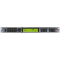
IEM - Processor DBX - Free user manual and instructions
Find the device manual for free IEM DBX in PDF.


| Product Type | Audio Processor |
| Brand | DBX |
| Model | IEM |
| Category | Processor |
| Chassis | 1U Rackmount |
| Dimensions (W x H x D) | 483 mm x 44 mm x 150 mm |
| Weight | 2.5 kg |
| Power Supply | 100-240 V AC, 50/60 Hz |
| Power Consumption | 20 W |
| Input Connections | XLR Balanced, 1/4" TRS |
| Output Connections | XLR Balanced, 1/4" TRS |
| Sample Rate | 48 kHz / 96 kHz |
| Bit Depth | 24-bit |
| Dynamic Range | >110 dB |
| Frequency Response | 20 Hz - 20 kHz ±0.5 dB |
| Signal Processing Functions | Compression, Limiting, EQ, Crossover, Delay |
| Presets | Factory and user presets |
| Control Interface | Front panel buttons and encoder, USB for software |
| Display | 2-line LCD with backlight |
| Operating Temperature | 0°C to 40°C |
| Cooling | Passive, no fan |
Frequently Asked Questions - IEM DBX
User questions about IEM DBX
0 question about this device. Answer the ones you know or ask your own.
Ask a new question about this device
Download the instructions for your Processor in PDF format for free! Find your manual IEM - DBX and take your electronic device back in hand. On this page are published all the documents necessary for the use of your device. IEM by DBX.
USER MANUAL IEM DBX

User Manual
IMPORTANT SAFETY INSTRUCTIONS

ATTENTION:

RISQUE DE CHOC ELECTRIQUE

NE PAS OUVRIR
WARNING: TO REDUCE THE RISK OF FIRE OR ELECTRIC SHOCK DO NOT EXPOSE THIS EQUIPMENT TO RAIN OR MOISTURE
The symbols shown above are internationally accepted symbols that warn of potential hazards with electrical products. The lightning flash with arrowpoint in an equilateral triangle means that there are dangerous voltages present within the unit. The exclamation point in an equilateral triangle indicates that it is necessary for the user to refer to the owner's manual.
These symbols warn that there are no user serviceable parts inside the unit. Do not open the unit. Do not attempt to service the unit yourself. Refer all servicing to qualified personnel. Opening the chassis for any reason will void the manufacturer's warranty. Do not get the unit wet. If liquid is spilled on the unit, shut it off immediately and take it to a dealer for service. Disconnect the unit during storms to prevent damage.
SAFETY INSTRUCTIONS
NOTICE FOR CUSTOMERS IF YOUR UNIT IS EQUIPPED WITH A POWER CORD.
WARNING: THIS APPLIANCE MUST BE EARTHED.
The cores in the mains lead are coloured in accordance with the following code:
GREEN and YELLOW - Earth
BLUE - Neutral
BROWN - Live
As colours of the cores in the mains lead of this appliance may not correspond with the coloured markings identifying the terminals in your plug, proceed as follows:
- The core which is coloured green and yellow must be connected to the terminal in the plug marked with the letter E, or with the earth symbol, or coloured green, or green and yellow.
- The core which is coloured blue must be connected to the terminal marked N or coloured black.
- The core which is coloured brown must be connected to the terminal marked L or coloured red.
This equipment may require the use of a different line cord, attachment plug, or both, depending on the available power source at installation. If the attachment plug needs to be changed, refer servicing to qualified service personnel who should refer to the table below. The green/yellow wire shall be connected directly to the units chassis.
| CONDUCTOR | WIRE COLOR | ||
| Normal Alt | |||
| L | LIVE | BROWN | BLACK |
| N | NEUTRAL | BLUE | WHITE |
| E | EARTH GND | GREEN/YEL | GREEN |
WARNING: If the ground is defeated, certain fault conditions in the unit or in the system to which it is connected can result in full line voltage between chassis and earth ground. Severe injury or death can then result if the chassis and earth ground are touched simultaneously.
WARNING FOR YOUR PROTECTION
PLEASE READ THE FOLLOWING:
KEEP THESE INSTRUCTIONS
HEED ALL WARNINGS
FOLLOW ALL INSTRUCTIONS
CLEAN ONLY WITH A DAMP CLOTH.
DO NOT BLOCK ANY OF THE VENTILATION OPENINGS. INSTALL IN ACCORDANCE WITH THE MANUFACTURERS INSTRUCTIONS.
DO NOT INSTALL NEAR ANY HEAT SOURCES SUCH AS RADIATORS, HEAT REGISTERS, STOVES; OR OTHER APPARATUS (INCLUDING AMPLIFIERS) THAT PRODUCE HEAT.
ONLY USE ATTACHMENTS/ACCESSORIES SPECIFIED BY THE MANUFACTURER.
UNPLUG THIS APPARATUS DURING LIGHTNING STORMS OR WHEN UNUSED FOR LONG PERIODS OF TIME.
WATER AND MOISTURE: Appliance should not be used near water (e.g. near a bathtub, washbowl, kitchen sink, laundry tub, in a wet basement, or near a swimming pool, etc). Care should be taken so that objects do not fall and liquids are not spilled into the enclosure through openings.
POWER SOURCES: The appliance should be connected to a power supply only of the type described in the operating instructions or as marked on the appliance.
GROUNDING OR POLARIZATION: Precautions should be taken so that the grounding or polarization means of an appliance is not defeated.
POWER CORD PROTECTION: Power supply cords should be routed so that they are not likely to be walked on or pinched by items placed upon or against them, paying particular attention to cords at plugs, convenience receptacles, and the point where they exit from the appliance.
SERVICING: To reduce the risk of fire or electric shock, the user should not attempt to service the appliance beyond that described in the operating instructions. All other servicing should be referred to qualified service personnel.
FOR UNITS EQUIPPED WITH EXTERNALLY ACCESSIBLE FUSE RECEPTACLE: Replace fuse with same type and rating only.
MULTIPLE-INPUT VOLTAGE: This equipment may require the use of a different line cord, attachment plug, or both, depending on the available power source at installation. Connect this equipment only to the power source indicated on the equipment rear panel. To reduce the risk of fire or electric shock, refer servicing to qualified service personnel or equivalent.
POWER ON / OFF SWITCH: The Power Switch used in this piece of equipment DOES NOT break the connection from the Mains.
IMPORTANT SAFETY INSTRUCTIONS
LITHIUM BATTERY WARNING
CAUTION!
This product may contain a lithium battery. There is danger of explosion if the battery is incorrectly replaced. Replace only with an Eveready CR 2032 or equivalent. Make sure the battery is installed with the correct polarity. Discard used batteries according to manufacturer's instructions.
ADVARSEL!
This unit conforms to the Product Specifications noted on the Declaration of Conformity. Operation is subject to the following two conditions:
- this device may not cause harmful interference, and
- this device must accept any interference received, including interference that may cause undesired operation.
Operation of this unit within significant electromagnetic fields should be avoided.
- use only shielded interconnecting cables.
U.K. MAINS PLUG WARNING
A molded mains plug that has been cut off from the cord is unsafe. Discard the mains plug at a suitable disposal facility. NEVER UNDER ANY CIRCUMSTANCES SHOULD YOU INSERT A DAMAGED OR CUT MAINS PLUG INTO A 13 AMP POWER SOCKET. Do not use the mains plug without the fuse cover in place. Replacement fuse covers can be obtained from your local retailer. Replacement fuses are 13 amps and MUST be ASTA approved to BS1362.
DECLARATION OF CONFORMITY
Manufacturer's Name: dbx Professional Products
Manufacturer's Address: 8760 S. Sandy Parkway
Sandy, Utah 84070, USA
declares that the product:
Product name: dbx IEM
Product option: N/A
conforms to the following Product Specifications:
Safety: EN 60065 (1993)
IEC65 (1985) with Amendments 1,2,3
EMC: EN 55013 (1990)
EN 55020 (1991)
Supplementary Information:
The product herewith complies with the requirements of the Low Voltage Directive 73/23/EEC and the EMC Directive 89/336/EEC as amended by Directive 93/68/EEC.
dbx Professional Products
Vice-President of Engineering
8760 S. Sandy Parkway
Sandy, Utah 84070, USA
February 15, 2001
European Contact: Your Local dbx Sales and Service Office or
Harman Music Group
8760 South Sandy Parkway
Sandy, Utah
84070 USA
PH: (801) 568-7660 FX: (801) 568-7662
Introduction
1.1 Defining the IEM......ii
1.2 Service Contact Info....ii
1.3 Warranty....iii
Section 1 - Getting Started
1.1 Rear Panel Connections....2
1.2 Front Panel 2
1.3 Signal Path....4
1.4 IEM Processing ....4
Section 2 - Navigation
2.1 Multiband Compressor....8
2.2 Multiband Limiter 9
2.3 EQ 10
2.4 X-Over....10
2.5 Stereo Adjust....11
2.6 Reverb....11
2.7 Peak Limiter....12
2.8 Utility....12
Section 3 - Software Operations
3.1 FX Chain 14
3.2 Saving a Program 14
3.3 The Bypass Function....15
3.4 Meters....15
3.5 Monitor Outputs....17
Section 4 - Detailed Parameters
4.1 Multiband Compression....20
4.2 Multiband Limiting 22
4.3 Peak Limiting....23
4.4 EQ 23
4.5 XOver....25
4.6 Stereo Adjust....25
4.7 Reverb....25
Section 5 - Utilities
5.1 Misc. 28
5.2 MIDI Channels....28
5.3 MIDI CC Map....28
5.4 MIDI Program Changes....29
5.5 SYSEX Program Dump....29
5.6 SYSEX Bulk Dump....29
5.7 A/D Calibrate....30
Section 6 - Application Guide
6.1 Mixer to IEM to In-Ear Transmitter .....32
6.2 Mixer to Xover to IEM ....33
Appendix
A.1 Hard & Soft Resets....36
A.2 Change Default Startup Program ....36
A.3 Front Panel Lockout ....36
A.4 Flash Downloads ....36
B Type IV™ White Paper 37
C Relay Mute/Bypass Jumpers....42
D MIDI SYSEX....43
E MIDI CC Tables....46
F Factory Presets....48
G Specifications....49
INTRODUCTION
INTRO
CUSTOMER SERVICE INFO
What is IEM?
WARRANTY INFO

INTRODUCTION
Congratulations on your purchase of the dbx IEM Processor! Finally! There is now a digital signal processor that has been designed specifically for in-ear monitor applications. Not only does the IEM provide legendary dbx effects in the digital domain, such as 4-band stereo compression and limiting, PeakStopPlus™ limiting and 5-band parametric EQ, but the IEM also includes stereo adjust, patented dbx Type IV™ conversion system, and for good measure, we have even raised the playing field by including custom reverb algorithms using Lexicon™ technology. The IEM from dbx Professional Products is a unit that is certain to take In-Ear Monitor processing to the next level.
This manual will be your guide to understanding the full functionality of the powerful IEM, read it carefully. After you have become familiar with the unit, we encourage you to experiment and find creative ways that the IEM can help you make a better sounding mix.
1.1 Defining the IEM
The dbx IEM is the first In-Ear monitor Processor to be designed exclusively for performer and engineers in live audio environments. The following list shows some of the features offered in the IEM.
- Lexicon™ Reverb Algorithms
- 48 bit internal dynamics signal path for increased headroom and low level resolution
- Patented TYPE IV™ A/D Conversion system with TSE™
• 4-band crossover with variable slopes - 4-band stereo Compressor and limiter with classic dbx Compression
- 5-band EQ - Hi and Lo shelves, 3 band fully parametric
- PeakStopPlus™ limiting
- Stereo adjust – to control your stereo image
- Software updateable via Internet and RS 232 port
1.2 Service Contact Info
If you require technical support, contact dbx Customer Service. Be prepared to accurately describe the problem. Know the serial number of your unit - this is printed on a sticker attached to the rear panel. If you have not already taken the time to fill out your warranty registration card and send it in, please do so now.
Before you return a product to the factory for service, we recommend you refer to the manual. Make sure you have correctly followed installation steps and operation procedures. If you are still unable to solve a problem, contact our Customer Service Department at (801) 568-7660 for consultation. If you need to return a product to the factory for service, you MUST contact Customer Service to obtain a Return Authorization Number.
No returned products will be accepted at the factory without a Return Authorization Number.
Please refer to the Warranty below, which extends to the first end-user. After expiration of the warranty, a reasonable charge will be made for parts, labor, and packing if you choose to use the factory service facility. In all cases, you are responsible for transportation charges to the factory. dbx will pay return shipping if the unit is still under warranty.
Use the original packing material if it is available. Mark the package with the name of the shipper and with these words in red: DELICATE INSTRUMENT, FRAGILE! Insure the package properly. Ship prepaid, not collect. Do not ship parcel post.
1.3 Warranty
This warranty is valid only for the original purchaser and only in the United States.
- The warranty registration card that accompanies this product must be mailed within 30 days after purchase date to validate this warranty. Proof-of-purchase is considered to be the burden of the consumer.
- dbx warrants this product, when bought and used solely within the U.S., to be free from defects in materials and workmanship under normal use and service.
- dbx liability under this warranty is limited to repairing or, at our discretion, replacing defective materials that show evidence of defect, provided the product is returned to dbx WITH RETURN AUTHORIZATION from the factory, where all parts and labor will be covered up to a period of two years. A Return Authorization number must be obtained from dbx by telephone. The company shall not be liable for any consequential damage as a result of the product's use in any circuit or assembly.
- dbx reserves the right to make changes in design or make additions to or improvements upon this product without incurring any obligation to install the same additions or improvements on products previously manufactured.
- The foregoing is in lieu of all other warranties, expressed or implied, and dbx neither assumes nor authorizes any person to assume on its behalf any obligation or liability in connection with the sale of this product. In no event shall dbx or its dealers be liable for special or consequential damages or from any delay in the performance of this warranty due to causes beyond their control.

1.1 Rear Panel Connections

IEC Power Cord Receptacle
The IEM comes with an international power supply that will accept voltages ranging from 100V-240V at frequencies from 50Hz-60Hz. An IEC cord is included.
RS-232 Port
This port is used as a direct interface between IEM and PC for utilization of the GUI software. This port is also used for firmware flash updates.
MIDI In and Out/Thru Connectors
These connectors provide full MIDI functionality to the IEM. The Out/Thru jack allows you to use the IEM at any point in the MIDI chain. For a complete guide to all the MIDI and SYSEX functionality of the IEM, see Section 3: Software Operations.
Analog Input/Output Connectors
Each analog channel features both XLR and 1/4" TRS electronically balanced connections. They may be used in a balanced or unbalanced configuration.
1.2 Front Panel

Analog Input and Output Level Controls
These controls adjust the analog audio levels of the IEM at the input and output stages. Note that the analog output level controls do not affect any digital processing.
The IEM is designed to interface as easily as possible to your system. The IEM uses wide ranging analog input and output gain controls. These controls allow the connection of nominal levels of either -10dBV or +4dBu.
Analog Level Meters
These meters monitor analog input and output. For more on meters refer to Section 3.
TSE™ Audio Level Meters
These meters monitor the level of Tape Saturation Emulation. Refer to Type IV ^TM in Section 3.
LCD Display
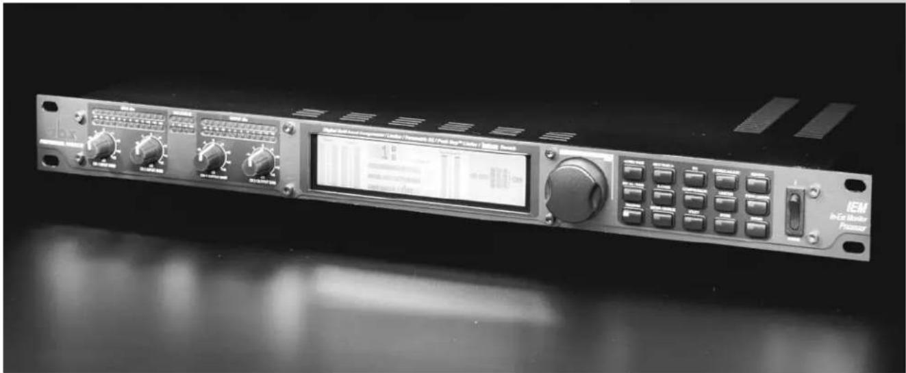
The large LCD display shows the program, dynamic curve, digital meters, parameters, and modules selected by the function buttons and the DATA WHEEL.
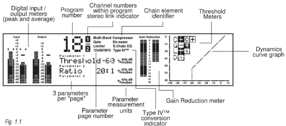
bar
| Parameter | Value | | :--- | :--- | | Multi-Band Compressor Gate Link | 1 | | De-esser Limiter | 2 | | S.Chain EQ 12345678910 | 3 | | Type IV™ | 4 | | Gain Reduction | 5 | | Gain Reduction meter | -15 | | 3 parameters per "page" | -2 | | Parameter measurement units | -3 | | Parameter page number | -4 | | Parameter measurement units | -5 | | Type IV™ conversion indicator | -6 | | Channel numbers within program stereo link indicator | -7 | | Chain element identifier | -8 | | Threshold Meters | -9 | | Digital input / output meters (peak and average) | -10 | | Program number | -11 | | Channel numbers within program stereo link indicator | -12 | | Channel numbers within program stereo link indicator | -13 | | Channel numbers within program stereo link indicator | -14 | | Channel numbers within program stereo link indicator | -15 | | Channel numbers within program stereo link indicator | -16 | | Channel numbers within program stereo link indicator | -17 | | Channel numbers within program stereo link indicator | -18 | | Channel numbers within program stereo link indicator | -19 | | Channel numbers within program stereo link indicator | -20 | | Channel numbers within program stereo link indicator | -21 | | Channel numbers within program stereo link indicator | -22 | | Channel numbers within program stereo link indicator | -23 | | Channel numbers within program stereo link indicator | -24 | | Channel numbers within program stereo link indicator | -25 | | Channel numbers within program stereo link indicator | -26 | | Channel numbers within program stereo link indicator | -27 | | Channel numbers within program stereo link indicator | -28 | | Channel numbers within program stereo link indicator | -29 | | Channel numbers within program stereo link indicator | -30 | | Channel numbers within program stereo link indicator | -31 | | Channel numbers within program stereo link indicator | -32 | | Channel numbers within program stereo link indicator | -33 | | Channel numbers within program stereo link indicator | -34 | | Channel numbers within program stereo link indicator | -35 | | Channel numbers within program stereo link indicator | -36 | | Channel numbers within program stereo link indicator | -37 | | Channel numbers within program stereo link indicator | -38 | | Channel numbers within program stereo link indicator | -39 | | Channel numbers within program stereo link indicator | -40 | | Channel numbers within program stereo link indicator | -41 | | Channel numbers within program stereo link indicator | -42 | | Channel numbers within program stereo link indicator | -43 | | Channel numbers within program stereo link indicator | -44 | | Channel numbers within program stereo link indicator | -45 | | Channel numbers within program stereo link indicator | -46 | | Channel numbers within program stereo link indicator | -47 | | Channel numbers within program stereo link indicator | -48 | | Channel numbers within program stereo link indicator | -49 | | Channel numbers within program stereo link indicator | -50 | | Channel numbers within program stereo link indicator | -51 | | Channel numbers within program stereo link indicator | -52 | | Channel numbers within program stereo link indicator | -53 | | Channel numbers within program stereo link indicator | -54 | | Channel numbers within program stereo link indicator | -55 | | Channel numbers within program stereo link indicator | -56 | | Channel numbers within program stereo link indicator | -57 | | Channel numbers within program stereo link indicator | -58 | | Channel numbers within program stereo link indicator | -59 | | Channel numbers within program stereo link indicator | -60 | | Channel numbers within program stereo link indicator | -61 | | Channel numbers within program stereo link indicator | -62 | | Channel numbers within program stereo link indicator | -63 | | Channel numbers within program stereo link indicator | -64 | | Channel numbers within program stereo link indicator | -65 | | Channel numbers within program stereo link indicator | -66 | | Channel numbers within program stereo link indicator | -67 | | Channel numbers within program stereo link indicator | -68 | | Channel numbers within program stereo link indicator | -69 | | Channel numbers within program stereo link indicator | -70 | | Channel numbers within program stereo link indicator | -71 | | Channel numbers within program stereo link indicator | -72 | | Channel numbers within program stereo link indicator | -73 | | Channel numbers within program stereo link indicator | -74 | | Channel numbers within program stereo link indicator | -75 | | Channel numbers within program stereo link indicator | -76 | | Channel numbers within program stereo link indicator | -77 | | Channel numbers within program stereo link indicator | -78 | | Channel numbers within program stereo link indicator | -79 | | Channel numbers within program stereo link indicator | -80 | | Channel numbers within program stereo link indicator | -81 | | Channel numbers within program stereo link indicator | -82 | | Channel numbers within program stereo link indicator | -83 | | Channel numbers within program stereo link indicator | -84 | | Channel numbers within program stereo link indicator | -85 | | Channel numbers within program stereo link indicator | -86 | | Channel numbers within program stereo link indicator | -87 | | Channel numbers within program stereo link indicator | -88 | | Channel numbers within program stereo link indicator | -89 | | Channel numbers within program stereo link indicator | -90 | | Channel numbers within program stereo link indicator | -91 | | Channel numbers within program stereo link indicator | -92 | | Channel numbers within program stereo link indicator | -93 | | Channel numbers within program stereo link indicator | -94 | | Channel numbers within program stereo link indicator | -95 | | Channel numbers within program stereo link indicator | -96 | | Channel numbers within program stereo link indicator | -97 | | Channel numbers within program stereo link indicator | -98 | | Channel numbers within program stereo link indicator | -99 | | Channel numbers within program stereo link indicator | -100 | Figure 1.1Data Wheel / Selector
The DATA WHEEL changes selected parameters, programs, etc. Pushing the DATA WHEEL moves the cursor from parameter to parameter.
Function Buttons
The function buttons allow access to the programs, modules, utilities, and parameters of the IEM. Bypass Note: To place the unit in bypass mode, you must press and hold the BYPASS button for approximately four seconds.
Power Switch
Turns the IEM on and off.
The Curve Window
After you have chosen a program, you may want to change some of the parameters to meet your specific needs. One of the most useful tools available in the IEM for setting up a proper compression curve is the curve window. In the curve window you can see the combined effects of dynamics-related parameters expressed in a graphical format. The figure below shows the different parts of the curve window you will see as you edit the compressor and limiter functions of the IEM.

scatter
| X | Y | |---|---| | -105 | 0 | | -90 | -90 | | -75 | -75 | | -60 | -60 | | -45 | -45 | | -30 | -30 | | -15 | -15 | | 0 | 0 | | 15 | 15 |When working with the EQ, the curve window changes to show a graphical representation of the 5 parametric bands in a frequency grid. Your adjustments to the 5 bands are shown in real time.
1.3 Signal Path
The following illustration shows how audio signals flow through the IEM.

flowchart
graph LR
    A["analog input"] --> B["TASE meter"]
    C["digital input"] --> D["TASE meter"]
    E["analog input control"] --> F["TYPE IV™ Conversion"]
    G["analog input"] --> H["A/D Converter"]
    I["digital input control"] --> J["TASE meter"]
    K["digital input"] --> L["TASE meter"]
    M["digital input"] --> N["TASE meter"]
    O["Digital Input"] --> P["Dynamics Processor"]
    Q["Digital Output"] --> R["D/A Converter"]
    S["Analog Output"] --> T["D/A Converter"]
    U["Bypass"] --> V["Sample Rate Converter"]
    W["Clone Bypass (push and hold Bypass for 2 seconds)"] --> X["Dither"]
    Y["Digital Output Meter"] --> Z["D/A Converter"]
    AA["Analog Output Meter"] --> AB["D/A Converter"]
Fig 1.2
Multiband compression/limiting is a three-step process. First, a crossover is used to separate the audio into different frequency bands. Next, separate compressors/limiters process the individual bands. Finally, the bands are summed back together. Because these bands contain different amounts of energy, they can be compressed using widely varying settings. The end result is that parts of the mix, the low frequency bands for example, can be compressed or limited more heavily than if a single compressor was used on the entire mix; thereby, allowing greater control over the output level.
The easiest way of setting up the multiband compressor in IEM is to use the monitor in conjunction with the crossover and the compressor/limiter.
The Monitor page allows the engineer to toggle the monitor position between the main L/R and individual bands both pre and post processing. By rotating the DATA WHEEL, the monitor position is changed.
The crossover page shows the crossover points as well as their slopes. The crossover points can be adjusted by rotating the DATA WHEEL and using the NEXT PAGE and PREV PAGE buttons to move between different crossover points. The slope can be changed by pushing the DATA WHEEL to move to the slope parameter line. Turning the DATA WHEEL changes the slope of the crossover. Changing the crossover slope changes the way the frequency bands interact. For example, a broader slope, e.g. 6 dB/Octave, allows the adjacent bands to have much more interaction than a slope of 18 dB/Octave. Broader slopes provide a more seamless transition between bands, while steeper slopes allow tighter control over a particular band.
Setting up your compressor/limiter is similar to setting up your crossover. You can listen to how the compression or limiting is affecting the individual bands by monitoring them both pre and post processing.
The Compressor page gives the engineer control over all the parameters that are needed to adjust the multiband compressor. The Multiband compressor can be adjusted either as a unit or the individual bands can be adjusted separately. By pushing the DATA WHEEL, the different
parameters on a page can be adjusted, and by pushing the NEXT PAGE and PREV PAGE buttons all the compressor parameters can be accessed. (for a complete list of compressor parameters please see Section 3, Software Operations). The different bands of the multiband compressor can be accessed by pressing the COMPRESSOR button. Each additional push of the COMPRESSOR button allows access to the next band.
As you have seen, by using the multiband compressor/limiter along with the other tools available in the IEM Processor, you will be able to create a realistic sounding, and more controlled in-car monitor mix.

NAVIGATION
Control of each of the bands within the IEM's multiband dynamic modules is made possible in two different ways. You may either use the "All page" or individual band adjustments. The "All page" is signified by a large "All" seen where the program number would normally be. Adjusting settings in this page will adjust the settings in all four bands as a group. To control individual bands within the "All page" press the EDIT ALL/BAND button to cycle through each band. Pressing the dynamic module's button again will cycle you through the separate bands and the dynamic controls of those bands e.g., compressor or limiter.
Refer to the Navigation illustrations for a complete view of the parameters available in each Multiband Dynamic Module.
2.1 Navigating the Multiband Compressor section

flowchart
graph TD
    A["All Bands"] --> B["Compr On/Loc/Off OverEasy® Auto Loc/On/Off"]
    A --> C["Threshold Ratio Gain"]
    A --> D["Attack Hold Release"]
    E["Band 1"] --> F["Band 1 On/Off OverEasy® Auto"]
    E --> G["Threshold Ratio Gain"]
    E --> H["Attack Hold Release"]
    I["Band 2"] --> J["Band 2 On/Off OverEasy® Auto"]
    I --> K["Threshold Ratio Gain"]
    I --> L["Attack Hold Release"]
    M["Band 3"] --> N["Band 3 On/Off OverEasy® Auto"]
    M --> O["Threshold Ratio Gain"]
    M --> P["Attack Hold Release"]
    Q["Band 4"] --> R["Band 4 On/Off OverEasy® Auto"]
    Q --> S["Threshold Ratio Gain"]
    Q --> T["Attack Hold Release"]
2.2 Navigating the Multiband Limiter section
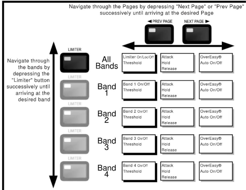
flowchart
graph TD
    A["All Bands"] --> B["Limiter On/Loc/Off Threshold"]
    A --> C["Attack Hold Release"]
    A --> D["OverEasy® Auto On/Off"]
    E["Band 1"] --> F["Band 1 On/Off Threshold"]
    E --> G["Attack Hold Release"]
    E --> H["OverEasy® Auto On/Off"]
    I["Band 2"] --> J["Band 2 On/Off Threshold"]
    I --> K["Attack Hold Release"]
    I --> L["OverEasy® Auto On/Off"]
    M["Band 3"] --> N["Band 3 On/Off Threshold"]
    M --> O["Attack Hold Release"]
    M --> P["OverEasy® Auto On/Off"]
    Q["Band 4"] --> R["Band 4 On/Off Threshold"]
    Q --> S["Attack Hold Release"]
    Q --> T["OverEasy® Auto On/Off"]
Navigate through the Parameters on each Page by depressing the data wheel. Rotating the data wheel changes the value of the Parameter.

2.3 Navigating the EQ Section

flowchart
graph TD
    A["EQ / XXOVER"] --> B["XOver"]
    C["EQ / XXOVER"] --> B
    D["EQ"] --> E["XOver"]
    F["Next Page"] --> G["Page 1 Page 2 Page 3 Page 4 Page 5 Page 6"]
    H["Prev Page"] --> I["Next Page"]
    J["EQ On/Off Pos Pre/Post Type"] --> K["Band 1 FC Slope Level"]
    L["Band 2 FC Q Level"] --> M["Band 3 FC Q Level"]
    N["Band 4 FC Q Level"] --> O["Band 5 FC Slope Level"]
    P["Edge 1 FC Slope"] --> Q["Edge 2 FC Slope"]
    R["Edge 3 FC Slope"] --> S["Edge 3 FC Slope"]
    T["The "EQ/XOver" button toggles between EQ and XOver. Depress once to access EQ and a second time for XOver"] --> B
    U["Navigate through the Parameters on each Page by depressing the data wheel. Rotating the data wheel changes the value of the Parameter."] --> V["●"]
2.4 Navigating the X-over Section
2.5 Navigating the STEREO ADJUST section
Navigate through the Pages by depressing "Next Page" or "Prev Page" successively until arriving at the desired Page


flowchart
graph TD
    A["Preview"] --> B["Next Page"]
    C["Page 1: St Adj On/Off Balance M-S ="] --> A
Navigate through the Parameters on each Page by depressing the data wheel. Rotating the data wheel changes the value of the Parameter.

2.6 Navigating the REVERB section
Navigate through the Pages by depressing "Next Page" or "Prev Page" successively until arriving at the desired Page


flowchart
graph LR
    A["PREV PAGE"] --> B["Page 1"]
    C["NEXT PAGE"] --> D["Page 2"]
    B --> E["Reverse Off/Type, Reverse Time Mix"]
    D --> F["Spread RTC Rolloff"]
Navigate through the Parameters on each Page by depressing the data wheel Rotating the data wheel changes the value of the Parameter.

2.7 Navigating the PEAK LIMITER section

flowchart
graph TD
    A["Peak Limiter"] --> B["PEAK LIMITER"]
    B --> C["Page 1"]
    C --> D["Page 2"]
    D --> E["Page 3"]
    E --> F["Over Easy AutoLevel"]
    G["PREV PAGE"] --> H["Next PAGE"]
    style A fill:#000,stroke:#fff,color:#fff
    style B fill:#000,stroke:#fff,color:#fff
    style C fill:#000,stroke:#fff,color:#fff
    style D fill:#000,stroke:#fff,color:#fff
    style E fill:#000,stroke:#fff,color:#fff
    style F fill:#000,stroke:#fff,color:#fff
    note right of A: "Navigate through the Pages by depressing 'Next Page' or 'Prev Page' successively until arriving at the desired Page"
    note right of F: "Navigate through the Parameters on each Page by depressing the data wheel. Rotating the data wheel changes the value of the Parameter."
2.8 Navigating the Utility section

flowchart
graph LR
    A["PREV PAGE"] --> B["NEXT PAGE"]
    B --> C["Page 1: Input Clock SRC"]
    C --> D["Page 2: Output BNC Freq"]
    D --> E["Page 3: DigIn Ch 1 DigIn Ch 2 HighPass on/off"]
    E --> F["Page 4: Chain Type MIDI CC # MIDI CC Effect"]
    F --> G["Page 5: MIDI CH Sysex Ch Merge On/Off"]
    G --> H["Page 6: Receive MIDI Prg as Prg"]
    H --> I["Page 7: Dump Setup Type"]
    I --> J["Page 8: Bulk Dump"]
    J --> K["Page 9: A/D Cal"]
    K --> L["Page 10: Contrast AutoLoad MtrSpeed"]
SOFTWARE OPERATIONS

SOFTWARE OPERATIONS
This section explains how signals are routed, monitored, and controlled in the IEM. Changes that are made to the IEM's dynamic processing can be monitored visually and aurally at several different points in the chain. Storing, and organizing user and factory programs in task specific libraries is also covered in this section. By following the outlined steps, you will quickly understand the usage and benefits of the IEM's storage system.
3.1 FX Chain
The following diagram shows the signal flow through the IEM's FX chain.
PEQ may be Pre or Post Dynamics
What the QUANTUM II screen shows for Pre:

flowchart
graph LR
    A["CH1"] --> B["Stereo Adjust"]
    C["CH2"] --> B
    B --> D["Pre PEQ"]
    D --> E["De-Esser"]
    E --> F["Crossover"]
    F --> G["Gate Comp Limiter"]
    F --> H["Gate Comp Limiter"]
    F --> I["Gate Comp Limiter"]
    F --> J["Gate Comp Limiter"]
    G --> K["+"]
    H --> K
    I --> K
    J --> K
    K --> L["Norm"]
    style A fill:#f9f,stroke:#333
    style C fill:#f9f,stroke:#333
    style B fill:#ccc,stroke:#333
    style D fill:#ccc,stroke:#333
    style E fill:#ccc,stroke:#333
    style F fill:#ccc,stroke:#333
    style G fill:#ccc,stroke:#333
    style H fill:#ccc,stroke:#333
    style I fill:#ccc,stroke:#333
    style J fill:#ccc,stroke:#333
    style K fill:#ccc,stroke:#333
    style L fill:#ccc,stroke:#333
Chain Type: Stereo Multi Band with De-Esser and Post-EQ
What the QUANTUM II

3.2 Saving a Program
Saving a program
Saving a program is done by following these steps:
- Press the STORE button. The screen looks like this.

-
At this point, you can edit the program name. The "curve window" shows instructions on how to do this. Using the DATA WHEEL as a "selector" and the PREV PAGE and NEXT PAGE buttons as the cursor, create the name you want to use, then press the store button to save the name.
-
Now the display will prompt you to either "Replace Old" or "Store New." By selecting "Replace Old," you will be replacing an existing program with your edited program in its place. If you replace, you will be given the option of which program you will be replacing.
By selecting “Store New,” you will store your edited program within the user program table. You will be given the option of placing your edited program anywhere within the user program table.
3.3 The Bypass Function
Bypass
To bypass the IEM, press and hold the BYPASS button for at least two seconds. All digital dynamics modules and reverb are rendered inactive.
3.4 Meters
Analog Meters
The IEM's analog input meters show the signal after the input controls. These analog meters are referenced in dBu. The meter will accurately represent the input level only when the input controls are set to zero.
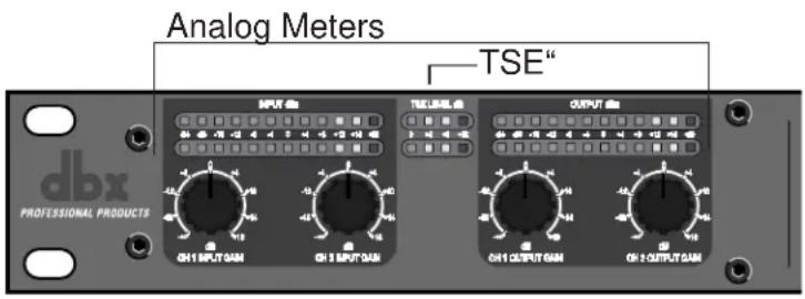
TSE™ Level Meters
These meters show that the program material has entered into Tape Saturation Emulation.
Digital Meters
The middle portion of the meter represents the peak level of the signal. The sides of the meter represent the average peak level. Digital clipping is represented by a large “C” at the top of the meter. PeakStopPlus ^™ limiting is represented by a large “P” at the top of the meter.

bar
| Region | Value | |---|---| | Peak | -2 | | Peak | -4 | | Peak | -6 | | Peak | -9 | | Peak | -12 | | Peak | -15 | | Peak | -20 | | Peak | -25 | | Peak | -30 | | Peak | -40 | | Peak | -50 | Input: +4, +2, 0, -2, -4, -6, -9, -12, -15, -20, -25, -30, -40, -50The Gain Reduction meters are a measurement of the sum of all active dynamic modules. In multiband mode, the meters function a little differently. Each LCD segment represents a separate band. This allows an accurate meter representation of the signal at a glance.

Threshold Meters
By pushing the METER/MONITOR button once, you can monitor all dynamics metering simultaneously. The compressor and limiter threshold meters show whether a signal has reached the threshold set in each dynamic processor. These threshold meters are indicated by -/0/+ symbols.
Compressor C: F0+
For the compressor, the threshold meter has three segments. The first is the minus (-) sign. It indicates that the threshold set in the compressor section is not being exceeded by the program material. There is no processing taking place in the compressor section if the threshold is not being exceeded, no matter what the other compressor settings are. The next part of the threshold meter is the "o". It represents the OverEasy® range of compression. When the signal level is in the OverEasy® range, the "o" part of the meter will be blackened, indicating that the signal is in the OverEasy® mode of compression. (For a complete explanation of the OverEasy® parameter, see Section 4.) The third segment of the compressor meter is the plus (+) sign. It is blackened when the signal is being fully compressed at the ratio set by the Ratio Parameter.
3.4 Meters (cont.)
Limiter/Peak Limiter
Both the multiband and output limiters threshold meters work on the same principle. When the signal is under the threshold setting, the signal is not being processed by the limiter section. The next part of the threshold meter is the "o". It represents the OverEasy® range of compression. When the signal exceeds the threshold set in the limiter section, the plus (+) sign will darken, and gain reduction will begin to occur as a result of the signal exceeding the limiter's threshold.
3.5 Monitor Outputs
Monitoring separate bands is a useful and easily accomplished function in the IEM. By pressing the METER/MONITOR button twice you are able to access the monitor selection page. Use the DATA WHEEL to select at which point you would like to monitor. The headphone graphic and arrow change to show the point in the signal chain you are monitoring. The text under “Monitor Out” shows which band and position you are currently selecting.
As you adjust the dynamic processing within individual bands it helps to monitor the changes made to those bands. While you monitor the individual bands it is recommended that adjustments be made prior to the performance. “Band 1 pre” monitor position is located just after the crossover, and before the multi-band compressor and limiter. “Band 1 post” is located after the multi-band compressor and limiter, and before the output peak limiter. The other bands (2-4) operate in the same fashion.
DETAILED PARAMETERS
4.1 Multiband Compression
Within the multiband compressor menu on the IEM the following parameters are user adjustable on all programs.
Compressor LOC/On/Off
Local (per band control) on and off.
Band 1 to 4 On/Off
Turns on or off each independent band
OverEasy® 1-10 (per band)
The point when the IEM (or any compressor) starts to compress is the "knee." When the IEM starts to reduce the level of a signal abruptly right as it passes over the threshold this is called "hard knee" compression. OverEasy® (soft knee as it is sometimes called) is when the level of the signal is compressed gradually. OverEasy® compression starts to compress before the level of the signal reaches the threshold and reaches full compression after the signal has gone above the threshold. This OverEasy® compression by its very nature sounds much smoother and more natural and will be used for most applications. When it is gentle (natural sounding or light) compression that you are looking for, the IEM has what we call VariKnee™. VariKnee™ gives you ten levels of OverEasy® compression to choose from (1 being almost hard knee and 10 being the most OverEasy®). This lets you choose the exact knee that is needed for the dynamic effect you are looking for.

line
| x | y | | ---- | ------ | | -60 | -60 | | -50 | -50 | | -40 | -40 | | -30 | -30 | | -20 | -30 | | -10 | -30 | | 0 | -30 |Fig. 4.1
Auto LOC/On/Off and Auto On/Off
Auto can be turned on/off per band or globally. When Auto mode is on, the IEM automatically sets the Attack, Hold, and Release times for the signal. The auto mode constantly adjusts these parameters in real time for optimum performance from the unit.
4.1 Multiband Compression (cont.)
Threshold -60 to 0 dB (per band)
Threshold is the signal level at which the IEM starts to compress. If the threshold is set to -10 dBFS, then any signal larger than -10 dBFS is compressed, while any signal that has a level lower than -10dBFS is left at the same level. Light compression is where only the largest parts of the signal go over the threshold. Very heavy compression can be achieved by setting the threshold low enough so that almost the entire signal content is over the threshold. For most signals, the most natural compression is achieved when most of the signal content remains just below the threshold and only the peaks cross the threshold.
Ratio 0.75 to Inf:1 (per band)
Ratio is the amount the IEM reduces the signal level of the sound that is above the threshold. A 2:1 ratio means that if the incoming signal is 2dB over the threshold the IEM will compress the signal, and outputs a signal that only goes 1dB over the threshold. For light compression choose a lower ratio. For heavy compression a higher ratio is used. By setting the ratio at less than 1:1, the signal will be expanded rather than compressed. The IEM will actually output a signal larger than the input. At a ratio of 0.75:1, if a signal goes over the threshold by 0.75dB the unit will output a signal that is 1 dB over the threshold.
Gain -20 to +20 dB (per band)
This is used to compensate for the gain lost during compression. By using heavy compression on a signal and then boosting the signal with the output gain we can than create a signal that sounds much louder than it was.
Attack 0.1 m Sec to 200 m Sec (per band)
Attack is how fast the compressor starts to compress the signal after it passes the threshold. Fast attack is useful when dealing with lots of fast transients. The attack control is not active when in auto mode.
Hold 0 to 500 m Sec (per band)
Hold is the time the IEM remains in compression after the signal has dropped below the threshold. A longer hold time is useful in smoothing out the sound when compressing several fast peaks that are fairly close together in time. In general, some hold time helps to make the compression sound more natural but too much can over compress your signal making for an unwanted drop in level. The hold control is not active while in auto mode.
Release 360 dB / Sec to 5 dB / Sec (per band)
Release is how fast the IEM comes out of compression. The release is in dB per second. For example, if release is set to 5 dB/sec, signal at 10dB of gain reduction, release time is 2 seconds. Too fast a release time can result in an audible volume jump, while too slow a release time can result in the compression of a signal that is not above the threshold. This can cause volume drops in your signal that may not be desired. The release control is not active while in auto mode.
4.2 Multi-band Limiting
A Limiter works very much like a compressor. The only difference is that on a limiter the ratio is set at infinity to one.
Whenever a signal crosses the threshold the limiter compresses it back down. By using the multiband Limiter you can set each limiter differently for different frequency ranges. The multiband limiter is an RMS limiter, short transients may exceed the threshold.
Within the limiter menu on the IEM the following parameters are user adjustable on all programs. (Changes made to factory programs can be saved as user programs.)
Limiter LOC/On/Off
Local (per band control) or global on or off.
Bands 1 to 4 On/Off
Lets you turn each band on or off independently.
Threshold -60 to 0 dB (per band or global)
It is recommended that the limiter's threshold be set to slightly below the point of no return so that there is a slight margin of safety. You, of course, want to be careful not to set the threshold to low as this would prevent you from getting the full dynamic range possible out of your gear. Finding the right limiter threshold for your equipment will take some experimentation. By dropping the threshold down below the bulk of the signal level we can then be limiting all the time. This will effectively take all the dynamics out of a signal and is used as a form of extra heavy compression.
OverEasy® Off to 10 (per band or global)
There are ten levels of OverEasy® that can be used on the IEM's limiters.
Auto On/Off/LOC and On/Off
When auto is turned on the IEM will continuously set the attack / hold / release controls itself. It can be set globally or locally per band.
Attack .01 to 200 m Sec (per band or global)
This is the speed at which the IEM limiter starts to compress the signal once it has crossed the threshold. Set the attack time longer for lower frequency bands, and shorter for higher frequency bands.
Hold 0 to 500 m Sec (per band or global)
Hold is the time the limiter stays in gain reduction after the signal level has dropped below threshold. Hold is useful when you want the limiter to function for a period of time after it has been triggered. Be careful not to set the hold time too long as it will not release in time.
Release 360 to 5 dB / Sec (per band or global)
Just like the release time on the compressor, the limiter's release time controls how fast the limiter releases from gain reduction after the signal drops below the threshold. Set the release times longer for lower frequency bands and shorter for higher frequency bands.
4.3 Peak Limiting
The PeakStopPlus™ limiter is a fail-safe Limiter is the last module in the signal path. This placement is to ensure that In-ear buds will not experience any unexpected or unwanted signal variance. If the Output Gain is set too high as compared to the PeakStopPlus™ Level control, continuous limiting can occur. Great care has gone into the design of the PeakStopPlus™ Limiter to keep it acoustically transparent. Appropriate use of it can protect your ears while keeping the signal free of artifacts. During PeakStopPlus™ limiting a large “P” is displayed at the top of the digital output meters.
Limiter On/Off
This parameter turns the PeakStopPlus ^TM limiter on and off.
Threshold -60dB to 0.0dB
This control sets the threshold level at which the PeakStopPlus ^TM Limiter circuit becomes active.
OverEasy® Off to 10 (per band or global)
There are ten levels of OverEasy® that can be used on the IEM's limiters.
Auto
When auto is turned on the IEM will continuously set the attack / hold / release controls itself.
Type PkStop+ or RMS
The Type parameter is used to select either the PeakStopPlus ^TM or RMS limiter.
Attack .01 to 200 m Sec
This is the speed at which the IEM limiter starts to compress the signal once it has crossed the threshold. Set the attack time longer for lower frequency bands, and shorter for higher frequency bands.
Hold 0 to 500 m Sec
Hold is the time the limiter stays in gain reduction after the signal level has dropped below threshold. Hold is useful when you want the limiter to function for a period of time after it has been triggered. Be careful not to set the hold time too long as it will not release in time.
Release 360 to 5 dB / Sec
Just like the release time on the compressor, the limiter's release time controls how fast the limiter releases from gain reduction after the signal drops below the threshold. Set the release times longer for lower frequency bands and shorter for higher frequency bands.
4.4 EQ
There are 5 bands of EQ on the IEM that can be used for something as subtle as sweetening a mix to drastic changes. Bands 1 and 5 are shelves while 2 through 4 are fully parametric.
Within the EQ menu the following parameters are user adjustable.
EQ On/Off
This control turns all 5 bands on and off.
Type Const Q / Adapt Q
This controls effects all 5 bands.
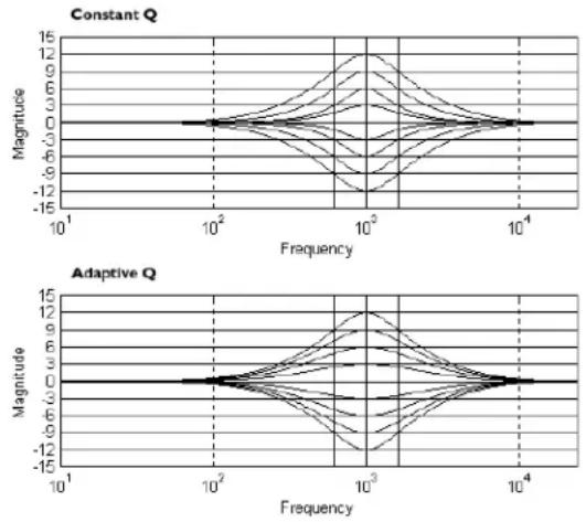
Const Q operates similar to an analog graphic EQ where the Q is constant regardless of cut or boost. Whereas, Adaptive Q, operates similar to the EQ that is found on a mixing console where the width of the band is constant regardless of the cut or boost.
The following figure shows the difference between constant and adaptive Q parametric filters.
Band 1 FC 20.0 Hz to 20.0 kHz
This controls the corner frequency for the low frequency shelving EQ band.
Slope 3 to 12 dB / Octave
Sets the slope of the shelf.
Level -12 to + 12 dB
Amount of boost or cut. Adjustable in 1/2 dB steps.
Band 2, 3, 4 FC 20.0 Hz to 20.0 kHz
This controls the center point for the parametric EQ.
Q 0.25 to 16.0
Sets the width of the boost / cut.
Level -12 to + 12 dB
Amount of boost or cut. Adjustable in 1/2 dB steps.
Band 5 FC 20.0 Hz to 20.0 kHz
This controls the corner frequency for the high frequency shelving EQ band.
Slope 3 to 12 dB / Octave
Sets the slope of the shelf.
Level -12 to + 12 dB
Amount of boost or cut. Adjustable in 1/2 dB steps.
4.5 X Over
There are three crossover points on the IEM, creating 4 bands. Tuning them allows you to select which frequencies to process with which of the multiband dynamics processors. The IEM uses phase compensated, Butterworth 1st and 3rd order filters.
Within the crossover menu on the IEM, the following parameters are user adjustable:
Sets the crossover point between bands 1 and 2.
Sets the crossover point between bands 2 and 3.
Sets the crossover point between bands 3 and 4.
Slope 6 or 18 dB / Octave (per band)
Your choice of 2 different slopes for each of the 3 crossover points.
4.6 Stereo Adjust
The "Stereo Adjust" control lets you change the width of the stereo mix.
St Adj On/Off
This parameter is used to turn the Stereo Adjust effect on and off.
Balance -100% to +100%
This lets you adjust the panning of your signal from one side to the other. 0% is center, so -100% becomes extreme left and +100% becomes extreme right.
M-S 100% to +100%
This controls the width of your stereo image. 0% is untouched so -100% becomes the narrowest (mono) while +100% become the widest possible stereo image.
4.7 Reverb
dbx Professional Products have included custom Lexicon® reverb algorithms in the IEM processor. By including these reverb algorithms, the IEM provides its user with ambience through their buds that normally can only be produced by real rooms. This means that the In-Ear-Monitor user does not have to except any compromises in sound quality.
Reverb Off-Types
This parameter is used to turn the Reverb effect off and select the various types. Types include: Room, Club, Small Hall, and Large Hall.
Reverb Time 0.32 to 3.29 seconds
This parameter sets the decay time of the reverb algorithm.
Mix 0 to 50%
This parameter is used to control the amount of reverb that is mixed into the signal path. Mix changes are made in .5% increments.
Spread 0 to 10
The Spread parameter controls the length of early reflections.
RTC (Room Time Constant) 1.00 to 8.00 kHz
The RTC parameter is used to simulate room absorption.
Rolloff 1.00 to 8.00 kHz
The Rolloff parameter is used to control the rolloff of the high frequencies at the output of the reverb.

UTILITIES
The IEM's "Utility" section contains many important operations. These operations affect the IEM on a global scale. This means that any changes that are made to this section affect all the presets. This global setup helps keep patching/routing consistent through all presets. If you are connecting inputs and outputs, or programming MIDI CC's, this is where it all happens.
5.1 Misc.
Contrast
The contrast selection adjusts the displays visibility.
Autoload Off/On
The Autoload on/off lets the user select the program load mode. Selecting autoload off will require that the user press the program button before the selected program loads. Whereas, autoload ON will automatically load programs once they are selected.
Meter speed
This utility feature allows the user to set the speed of the various meters within the IEM. Speeds include: Low, Med and High.
5.2 MIDI Channels
MIDI CH
Selects which MIDI channel the IEM will receive program changes and CC's on. Selections are; OFF, 1-16, OMNI.
SYSEX CH
Selects which MIDI channel the IEM will receive SYSEX information on. Selections are; OFF, 1-16, OMNI.
Merge
MIDI merging allows any incoming MIDI data to be merged with MIDI data generated by the IEM. This merged data will then be transmitted to the MIDI out port. Selections are ON/OFF.
5.3 MIDI CC Map
MIDI
The IEM has been engineered to provide the user with a mind boggling array of MIDI controllable parameters. This means that once you have set up your MIDI device it will control the same parameters in all presets. This allows you to concentrate on the mix.
There are three MIDI CC maps, one for each chain type. Each map assigns the CC for all programs which use that chain type.
MIDI CC
Selects the MIDI Continuous Controller number to be used. Controllers range from 0-127. A MIDI Continuous Controller may be 'Linked' to nearly any available parameter in the IEM. Moving the cursor down once allows you to change which parameter is controlled by the chosen CC number. With the amount of CC controllable parameters available, you will want to assign them to everything. As you scroll through assignable parameters the available dynamic module that each parameter is a part of is listed under the graphic representation of the chain on the lower right hand quadrant. Refer to Appendix E for assignable parameters.
5.4 MIDI Program Changes
Program Changes:
When the IEM is set to receive on one or all of the MIDI channels, it will recognize a Program Change command. If the number is legal (i.e., within the device's range of selectable programs) the IEM will respond by changing to the new program. MIDI sends Program Changes 0 through 127. The IEM begins its program numbering with 1, thus Program Change 0 will select program 1. The IEM also allows the user to 're-map' the Program Change commands so that Program Change 0 could call program 60, if so desired.
5.5 SYSEX Program Dump
The IEM has the ability to dump an individual Program as a MIDI number other than its own. This is particularly useful in cases where you need to perform Program dumps from one IEM to another, and you don't want to overwrite the corresponding Program number in the destination unit. To dump an individual Program, do the following:
- Enter the "Utility" menu by pressing the UTILITY button once.
- Press NEXT PAGE button until page 5 is reached.
- Use the DATA WHEEL to select which program you would like to dump.
- Press the DATA WHEEL to change the cursor location to the next selection.
5 Select the name of the preset you would like to dump. - Press the UTILITY button to start the dump.
5.6 SYSEX Bulk Dump
About SYSEX Dumps
The IEM allows you to use MIDI to archive the settings in your unit or even settings of each individual setup. This is done through MIDI System Exclusive data protocols. System Exclusive data, or SYSEX as it is often called, can be shared between two IEM's by simply connecting the MIDI Out of one IEM to the MIDI In of the other. To ensure data integrity, the two IEM's should be using the same software version (the version is displayed when the unit powers up). Data can also be sent to an external MIDI recording device, such as a MIDI sequencer or a computer outfitted with a proper MIDI interface. Once the data is there, it can be sent back to the IEM to restore settings to their archived values.
System SYSEX Data: The BULK DUMP option allows a complete system exclusive dump of the entire contents of the IEM's memory. This includes all user Programs, Utility, and MIDI configurations. To perform a system exclusive dump of the entire contents of the memory, do the following:
- Enter the "Utility" menu by pressing the UTILITY button once.
- Press NEXT PAGE button until page 6 is reached.
- Press UTILITY button to dump the entire contents of the IEM's memory.
5.7 A/D Calibrate
A/D Calibrate
This page of “Utilities” is a calibration section for the analog to digital converter chips. To calibrate the converters, first turn the input controls of the IEM fully counter-clockwise (-∞). Calibrations performed with these controls open at all could result in inaccurate calibrations, giving the IEM poor processing performance. After the input controls have been turned to the
(-∞) position, press the UTILITY button. If the calibration is not successful, the following text will appear in the third parameter area: "A/D CAL FAIL!" If this happens you should turn the IEM off then back on. If the problem persists, call dbx technical support at 1-801-568-7660 for assistance. Call after the unit is allowed to warm up to operating temperature (approx. 10 minutes).
APPLICATION
GUIDE

6.1 Mixer to IEM
Hardware
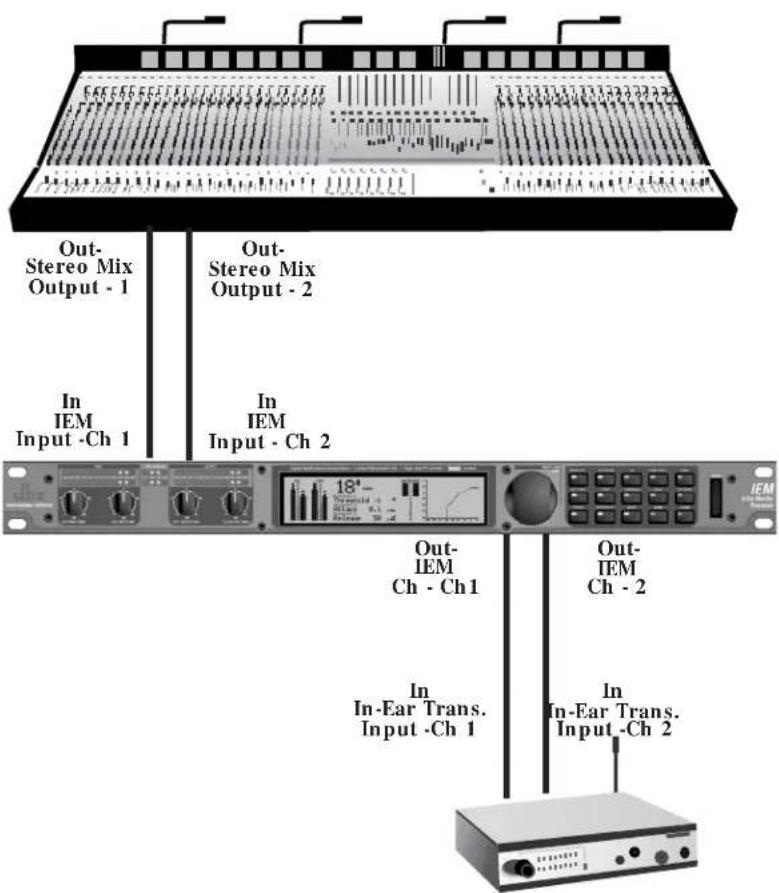
- Connect the stereo mix output 1 and 2 from the mixer to Inputs 1 and 2 of the IEM
- Connect Outputs 1 and 2 from the IEM to inputs 1 and 2 of the Wireless Transmitter.
Software
- Once signal is passing through the unit, adjust levels on the front panel of the IEM.
- Make adjustments to each individual effect by pressing each respective effect button, and then proceed to make parameters adjustments accordingly.
6.2 Mixer to IEM with Bandpass Sub
Hardware
- Connect the stereo mix output 1 and 2 from the mixer to Inputs 1 and 2 of the selected crossover, sending the High/Mid or Fullrange outputs to the IEM, and the low outputs to the amplifier.
- Connect Outputs 1 and 2 from the IEM to inputs 1 and 2 of the Wireless Transmitter.
Software
- Once signal is passing through the unit, adjust levels on the front panel of the IEM.
- Make adjustments to each individual effect by pressing each respective effect button, and then proceed to make parameters adjustments accordingly.

flowchart
graph TD
    A["In In-Ear Trans. Input -Ch 1"] --> B["Out-IEM Ch - Ch 1"]
    C["In In-Ear Trans. Input -Ch 2"] --> D["Out-IEM Ch - Ch 2"]
    E["X-Over"] --> F["In IEM Input -Ch 1"]
    F --> G["Out-Sterco Mix Output - 1"]
    G --> H["Out-Sterco Mix Output - 2"]
    H --> I["Power Amp"]
    I --> J["Subwoofer"]
![Jpx Digital Audio Modemeter [Audio/Modemeter] (100% Power Factor Generator) [Signal Modemeter] IEM In-Theta Marker Primer](/content/2026/06/1369077/images/8ee1c7fee14bc11ffc766fa5a421ef505926ec025fcd4ff858ac551b269ce894.jpg)
A.1 Hard & Soft Resets
Occasionally, it may be necessary to perform a "Soft" or "Hard" reset. The Soft Reset resets everything except user programs. The Hard Reset Procedure will reset all programable information back to the factory defaults.
Todo a Hard Reset:
Press and hold
!:HARD RESET?
YES
NO
Todo a Soft Reset:
Press and hold
*:SOFT RESET
YES
NO
A.2 Change Default Startup Program
The IEM turns on in "Program Mode" and is ready to use without any other keystrokes. The IEM "remembers" the last program number used, and stores that program number as the default startup program. Occasionally, you may wish to change this setting. Changing the startup program allows you to set the IEM to power-up to any selected program. This can be accomplished by pressing and holding the PROGRAM button during power up UNTIL "CHG RESTART" appears on the LCD. Select Startup Program with the encoder. Press
A.3 Front Panel Lockout
The IEM's controls may also be locked, effectively disabling the front panel. Pressing and holding the UTILITY button, while powering on the IEM displays an instruction screen telling you to press the PREV PAGE button to toggle the locked status. When locked, the text "Locked!" flashes on the LCD. Unlocking the IEM is accomplished the same way. Note that when locked, the IEM can still be controlled via MIDI operations.
A.4 Flash Downloads
The IEM has the ability to update its operating system (OS) to the latest version available over the Internet.
- Connect a null modem cable from the serial output of your PC to the IEM.
- Access the World Wide Web.
- Go to www.dbxpro.com to access the latest OS version.
- Download the latest OS version and all attached software.
- Follow instructions on the website.
dbx Type IV™ Conversion System White Paper by Roger Johnson
The dbx Type IV ^TM Conversion System is a proprietary analog-to-digital (A/D) conversion process that combines the best attributes of digital conversion and analog recording processes to preserve the essence of the analog signal when it is converted to a digital format. dbx Type IV ^TM not only exploits the wide linear dynamic range of today's A/D converters, but also enhances it and extends the useable dynamic range beyond the linear range. By providing a logarithmic “Type IV ^TM Over Region” above the linear A/D range, we benefit from the extended high-level headroom that is inherent in analog recording without compromising the noise performance of the A/D conversion process.
Digital conversion and recording processes proliferated in the 1980's primarily due to the "cleaner" sound of digital versus analog, an advantage resulting from the comparatively wider linear dynamic range of digital. Anyone who is familiar with the technical specifications of digital equipment knows that the typical maximum signal-to-noise specifications for 16-bit systems is in the neighborhood of 90-something dB. Compare this to the typical signal-to-noise specifications for professional analog tape of about 55 dB without the aid of noise reduction and around 75 to 85 dB with noise reduction such as dbx Type I ^TM or Type II ^TM applied.
This seemingly tremendous signal-to-noise advantage of digital over analog would suggest that digital would become the unanimous choice for recording. For the most part this has occurred, not totally due to its signal-to-noise advantage, but as much due to the benefits of digital storage such as random access and the inherent ability to withstand degradation, unlike that of analog tape or LP's. In spite of the benefits of digital, no one in the audio world can refute the rediscovery of analog recording and tube gear that has occurred in the 90's, attributable to the quest for that "analog character" that is missing from digital recordings. This continued use of analog gear with modern digital systems brings to light a favorable characteristic of analog recording which those who abandoned analog and jumped on the digital bandwagon were either never aware of or simply took for granted.
Anyone who has ever used analog tape knows that you can “hit it hard” without destroying the recording. The printed specifications of analog tape don’t take into account the practical headroom available. The max signal-to-noise specification of analog tape is measured by defining the “max” signal as the point where a given signal level and frequency produces a given percent Total Harmonic Distortion (THD)—typically the level at which a 1 kHz signal produces 3% THD. In actual use, the signal can easily exceed this “max” signal level by 5, 10, or even 15 dB on peaks, depending on the type of signal being recorded, without unacceptable artifacts. High signal levels can be tolerated (i.e. more headroom) at the expense of increased THD which, incidentally, is often desirable as an effect, evidenced by the renewed popularity of tube equipment.
The obvious conclusion is that analog recording actually has more useable dynamic range than the specifications seem to indicate. For example, let's say we're recording a kick drum. If analog tape measures 55 dB from the 3% THD point down to the RMS noise floor and the peaks of the kick drum exceed the 3% THD level by, say, 15 dB and it still sounds good, then we have 15 dB of extra useable headroom. Therefore, we end up with 70 dB of useable dynamic range. Throw in noise reduction and we push into the 90-something dB dynamic range territory of 16-bit digital. This explains why well-recorded analog master tapes make good-sounding CD's with no objectionable noise.
One main drawback of digital is that it inherently lacks this forgiving and beneficial characteristic of analog recording. Although digital conversion exhibits wide linear dynamic range, when you run out of headroom for high-level signals, hard clipping or even ugly signal wrap-around occurs, not to mention that A/D converters have their own nasty side effects such as going unstable when their modulator is overdriven with high-level signals.
This shortcoming of digital conversion has drastically affected the way users operate their equipment. Users are paranoid of overdriving the converter input and end up recording at lower levels to ensure that there is ample headroom to allow for the large peaks that would ruin an otherwise perfect recording. This, of course, compromises signal-to-noise performance since the signal is now closer to the noise floor. Because users of digital equipment have to be extremely careful not to exceed 0 dB FS (full-scale), they must use peak-reading headroom meters. On the other hand, the forgiving nature of analog tape allows users of analog recording equipment the luxury of only needing to monitor the average level using VU meters, often having no peak indicators whatsoever. If only digital were more forgiving like
analog, we could really exploit its wide dynamic range and more completely capture the essence of the musical performance.
Enter the dbx Type IV ^TM Conversion System. Like its related predecessor technologies—Type I ^TM , Type II ^TM , and Type III ^TM —dbx Type IV ^TM succeeds in preserving the wide dynamic range of the original analog signal within a limited dynamic range medium. Whereas Type I ^TM and Type II ^TM expand the dynamic range of analog tape and other limited dynamic range media, and the simultaneous encode/decode process of Type III ^TM similarly expands the limited dynamic range through minimum-delay devices, Type IV ^TM breaks new ground by greatly enhancing the useable dynamic range of the analog-to-digital conversion process.
The dbx Type IV ^TM Conversion System combines proprietary analog and digital processing techniques to capture a much wider dynamic range than the A/D converter could by itself, preserving the maximum amount of information from the analog signal. This information is then encoded within the available bits of whichever A/D converter is used. This means that Type IV ^TM improves the performance of any A/D converter, from low-cost 16-bit to high-performance 24-bit! And no decoding is necessary beyond the conversion process!
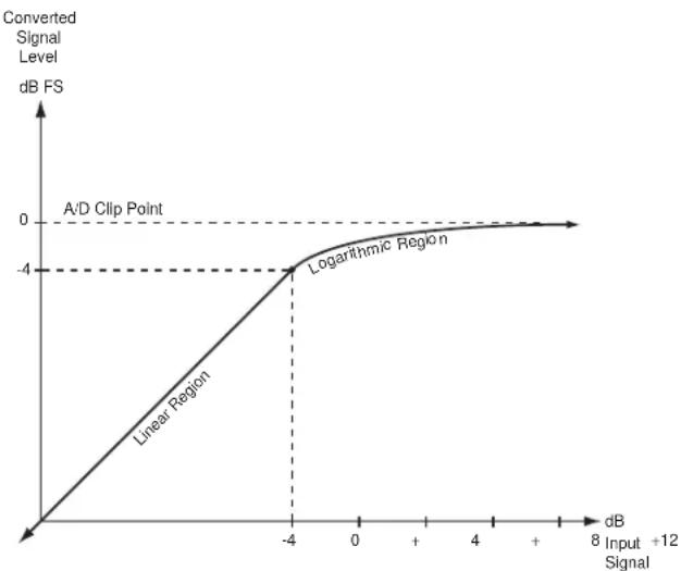
As we have previously mentioned, digital systems have a wide linear region compared to analog tape and the dynamic range of A/D converters has improved significantly in recent years. The dbx Type IV ^TM Conversion System takes advantage of this and utilizes the top 4 dB of the A/D converter's linear dynamic range to create a logarithmic “overload region.” This allows high-level transient signals passing far above the point where the overload region begins to be adequately represented in just 4 dB of the converter's dynamic range, whereas a typical A/D converter would clip. With Type IV ^TM , you can never clip the A/D converter!
line
| Input Signal | Converted Signal Level (dB FS) | | ------------ | ------------------------------ | | -4 | -4 |Figure 1 - Converted Level vs. Input Level
Fig. 1 illustrates this concept showing the level of the converted signal below and above the start of the overload region. The converted signal level is plotted along the Y-axis (vertical axis) of the plot vs. the level of the input signal along the X-axis (horizontal axis). The logarithmic mapping of the overload region begins 4 dB below 0 dB FS (full-scale) of the A/D converter. What this shows is that below -4 dB FS, in the linear region, the output signal is the same as the input signal. Above this, in the logarithmic region, high-level input signals get “mapped” into the top 4 dB of the A/D converter. This mapping is analogous to the signal compression effect that occurs when recording high-level signals onto analog tape.

Figure 2 - Input Signal Levels Mapped to Type IV Over Region
Fig. 2 illustrates the mapping function in a different way. Input levels are shown on the left of the graph, while converted levels are shown on the right. Notice the mapping of large signal excursions to the 4 dB "Type IV™ Over Region."
One might question the validity of such an approach—trying to represent a lot of signal information within a smaller “space.” The reason why this is not only valid but makes a whole lot of sense is that the digital codes in a converter are linear, or evenly-spaced, meaning that each consecutive code represents the same change in voltage of the input signal. This implies that half of the digital codes are used to represent input signals whose voltage level is below 1/2 of the full-scale A/D input voltage, while the other half of the codes are used to represent signals above 1/2 of the full-scale A/D input voltage. This seems reasonable until you realize that 1/2 of the full-scale input is only 6 dB below full-scale! So half of the codes are used to represent only the top 6 dB of signal information, while the other half are used to represent the remaining 80 to 110 dB of signal information, depending on the quality of the converter. It seems not only reasonable, but also desirable, to utilize the increased signal resolution afforded by this density of digital codes to represent more input dynamic range in this region.
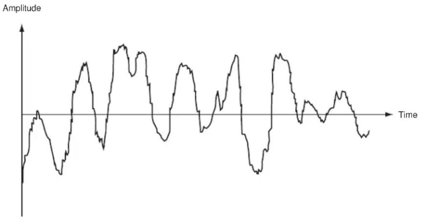
Another advantage of the logarithmic mapping of our dbx Type IV ^TM Conversion System is that it preserves the high-frequency detail of the signal in the overload region. Figs. 3a through 3d illustrate what happens when you overload an A/D converter without Type IV ^TM . Fig. 3a shows an input signal having both low-frequency and high-frequency components. When the signal overloads, or clips, (Fig. 3b) at the A/D converter, a disproportionate amount of high-frequency signal information is lost compared with the low-frequency information. The low and high-frequency components of the signal are separated in Fig. 3c to illustrate this more clearly. As you can see, the low frequency signal simply gets distorted but maintains most of its signal characteristics, while sections of the high-frequency signal are completely lost! With dbx Type IV ^TM , its mapping preserves high-frequency signal information, as illustrated in Fig. 3d, since the signal is confined within the Type IV ^TM Over Region and never clips. The dashed line indicates the original input signal level. Below the Over Region no mapping occurs, while above this, mapping keeps all peaks of the signal below the A/D clip level, thus preserving the high-frequency content of the signal.
line
| Time | Amplitude | |------|---------| | 0 | 0 | | 1 | 1 | | 2 | -1 | | 3 | 2 | | 4 | -2 | | 5 | 3 | | 6 | -3 | | 7 | 4 | | 8 | -4 | | 9 | 5 | | 10 | -5 | | 11 | 6 | | 12 | -6 | | 13 | 7 | | 14 | -7 | | 15 | 8 | | 16 | -8 | | 17 | 9 | | 18 | -9 | | 19 | 10 | | 20 | -10 | | 21 | 11 | | 22 | -11 | | 23 | 12 | | 24 | -12 | | 25 | 13 | | 26 | -13 | | 27 | 14 | | 28 | -14 | | 29 | 15 | | 30 | -15 | | 31 | 16 | | 32 | -16 | | 33 | 17 | | 34 | -17 | | 35 | 18 | | 36 | -18 | | 37 | 19 | | 38 | -19 | | 39 | 20 | | 40 | -20 | | 41 | 21 | | 42 | -21 | | 43 | 22 | | 44 | -22 | | 45 | 23 | | 46 | -23 | | 47 | 24 | | 48 | -24 | | 49 | 25 | | 50 | -25 | | 51 | 26 | | 52 | -26 | | 53 | 27 | | 54 | -27 | | 55 | 28 | | 56 | -28 | | 57 | 29 | | 58 | -29 | | 59 | 30 | | 60 | -30 | | 61 | 31 | | 62 | -31 | | 63 | 32 | | 64 | -32 | | 65 | 33 | | 66 | -33 | | 67 | 34 | | 68 | -34 | | 69 | 35 | | 70 | -35 | | 71 | 36 | | 72 | -36 | | 73 | 37 | | 74 | -37 | | 75 | 38 | | 76 | -38 | | 77 | 39 | | 78 | -39 | | 79 | 40 | | 80 | -40 | | 81 | 41 | | 82 | -41 | | 83 | 42 | | 84 | -42 | | 85 | 43 | | 86 | -43 | | 87 | 44 | | 88 | -44 | | 89 | 45 | | 90 | -45 | | 91 | 46 | | 92 | -46 | | 93 | 47 | | 94 | -47 | | 95 | 48 | | 96 | -48 | | 97 | 49 | | 98 | -49 | | 99 | 50 | | 100 | -50 |Figure 3a - Signal Having Low and High Frequency Content

line
| Time | Amplitude | |------|---------| | 0 | 0 | | 1 | 1 | | 2 | -1 | | 3 | 2 | | 4 | -2 | | 5 | 3 | | 6 | -3 | | 7 | 4 | | 8 | -4 | | 9 | 5 | | 10 | -5 | | 11 | 6 | | 12 | -6 | | 13 | 7 | | 14 | -7 | | 15 | 8 | | 16 | -8 | | 17 | 9 | | 18 | -9 | | 19 | 10 | | 20 | -10 | | 21 | 11 | | 22 | -11 | | 23 | 12 | | 24 | -12 | | 25 | 13 | | 26 | -13 | | 27 | 14 | | 28 | -14 | | 29 | 15 | | 30 | -15 | | 31 | 16 | | 32 | -16 | | 33 | 17 | | 34 | -17 | | 35 | 18 | | 36 | -18 | | 37 | 19 | | 38 | -19 | | 39 | 20 | | 40 | -20 | | 41 | 21 | | 42 | -21 | | 43 | 22 | | 44 | -22 | | 45 | 23 | | 46 | -23 | | 47 | 24 | | 48 | -24 | | 49 | 25 | | 50 | -25 | | 51 | 26 | | 52 | -26 | | 53 | 27 | | 54 | -27 | | 55 | 28 | | 56 | -28 | | 57 | 29 | | 58 | -29 | | 59 | 30 | | 60 | -30 | | 61 | 31 | | 62 | -31 | | 63 | 32 | | 64 | -32 | | 65 | 33 | | 66 | -33 | | 67 | 34 | | 68 | -34 | | 69 | 35 | | 70 | -35 | | 71 | 36 | | 72 | -36 | | 73 | 37 | | 74 | -37 | | 75 | 38 | | 76 | -38 | | 77 | 39 | | 78 | -39 | | 79 | 40 | | 80 | -40 | | 81 | 41 | | 82 | -41 | | 83 | 42 | | 84 | -42 | | 85 | 43 | | 86 | -43 | | 87 | 44 | | 88 | -44 | | 89 | 45 | | 90 | -45 | | 91 | 46 | | 92 | -46 | | 93 | 47 | | 94 | -47 | | 95 | 48 | | 96 | -48 | | 97 | 49 | | 98 | -49 | | 99 | 50 | | 100 | -50 |Figure 3b - Signal of Fig. 3a Going Beyond the A/D Clip Level

line
| Time | High-Frequency Information Completely Lost | Low-Frequency Content | |------|-------------------------------------------|------------------------| | 0 | 0 | 0 | | 1 | 0 | 0 | | 2 | 0 | 0 | | 3 | 0 | 0 | | 4 | 0 | 0 | | 5 | 0 | 0 | | 6 | 0 | 0 | | 7 | 0 | 0 | | 8 | 0 | 0 | | 9 | 0 | 0 | | 10 | 0 | 0 | | 11 | 0 | 0 | | 12 | 0 | 0 | | 13 | 0 | 0 | | 14 | 0 | 0 | | 15 | 0 | 0 | | 16 | 0 | 0 | | 17 | 0 | 0 | | 18 | 0 | 0 | | 19 | 0 | 0 | | 20 | 0 | 0 | | 21 | 0 | 0 | | 22 | 0 | 0 | | 23 | 0 | 0 | | 24 | 0 | 0 | | 25 | 0 | 0 | | 26 | 0 | 0 | | 27 | 0 | 0 | | 28 | 0 | 0 | | 29 | 0 | 0 | | 30 | 0 | 0 | | 31 | 0 | 0 | | 32 | 0 | 0 | | 33 | 0 | 0 | | 34 | 0 | 0 | | 35 | 0 | 0 | | 36 | 0 | 0 | | 37 | 0 | 0 | | 38 | 0 | 0 | | 39 | 0 | 0 | | 40 | 0 | 0 | | 41 | 0 | 0 | | 42 | 0 | 0 | | 43 | 0 | 0 | | 44 | 0 | 0 | | 45 | 0 | 0 | | 46 | 0 | 0 | | 47 | 0 | 0 | | 48 | 0 | 0 | | 49 | 0 | 0 | | 50 | 0 | 0 | | 51 | 0 | 0 | | 52 | 0 | 0 | | 53 | 0 | 0 | | 54 | 0 | 0 | | 55 | 0 | 0 | | 56 | 0 | 0 | | 57 | 0 | 0 | | 58 | 0 | 0 | | 59 | 0 | 0 | | 60 | 0 | 0 | | 61 | 0 | 0 | | 62 | 0 | 0 | | 63 | 0 | 0 | | 64 | 0 | 0 | | 65 | 0 | 0 | | 66 | 0 | 0 | | 67 | 0 | 0 | | 68 | 0 | 0 | | 69 | 0 | 0 | | 70 | 0 | 0 | | 71 | 0 | 0 | | 72 | 0 | 0 | | 73 | 0 | 0 | | 74 | 0 | 0 | | 75 | 0 | 0 | | 76 | 0 | 0 | | 77 | 0 | 0 | | 78 | 0 | 0 | | 79 | 0 | 0 | | 80 | - | - | | ... (final) - A/D Clip Level - High-Frequency Information Completely Lost - High-Frequency Content - Low-Frequency Content - High-Frequency Information Completely Lost - High-Frequency Content - Low-Frequency Content - High-Frequency Information Completely Lost - High-Frequency Content - Low-Frequency Content - High-Frequency Information Completely Lost - High-Frequency Content - Low-Frequency Content - High-Frequency Information Completely Lost - High-Frequency Content - Low-Frequency Content - High-Frequency Content - Low-Frequency Content - High-Frequency Content - Low-Frequency Content - High-Frequency Content - Low-Frequency Content - High-Frequency Content - Low-Frequency Content - High-Frequency Content - Low-Frequency Content - High-Frequency Content - Low-Frequency Content - High-Frequency Content - Low-Frequency Content - High-Frequency Content - Low-Frequency Content - High-Frequency Content - Low-Frequency Content - High-Frequency Content - Low-Frequency content - High-Frequency content - Low Freq. - High Freq. - Low Freq. - High Freq. - Low Freq. - High Freq. - Low Freq. - High Freq. - Low Freq. - High Freq. - Low Freq. - High Freq. - Low Freq. - High Freq. - Low Freq. - High Freq. - Low Freq. - High Freq. - Low Freq. - High Freq. - Low Freq. - High Freq. (final value) < A/D Clip Level < High Frequency Information Completely Lost < Low Frequency Content < Low Freq. < High Frequency Content < High Frequency Content < Low Frequency Content < High Frequency Content < Low Frequency Content < High Frequency Content < Low Frequency Content < High Frequency Content < Low Frequency Content < High Frequency Content < Low Frequency Content < High Frequency Content < Low Frequency Content < High Frequency Content < Low Frequency Content < High Frequency Content < Low Frequency Content < High Frequency Content < Low Frequency Content < High Frequency Content < Low Frequency Content < High Frequency Content < Low Frequency Content < High Frequency Content < Low Frequency Content < High Frequency Content < Low Frequency Content < Low Frequency Content < High Frequency Content < Low Frequency Content < High Frequency Content < Low Frequency Content < High Frequency Content < Low Frequency Content < High Frequency Content < Low Frequency Content < High Frequency Content < Low Frequency Content < High Frequency Content < Low Frequency Content < High Frequency Content < Low Frequency Content < High Frequency Content < Low Frequency Content < High Frequency Content < Low Frequency Content < High Frequency Content < Low Frequency Content < High Frequency Content < Low Frequency Content < High Frequency Content < Lower A/D Clip LevelFigure 3c - Disproportionate Loss of High-Frequency Information Due to Clipping

line
| Time | Amplitude (dB FS) | |------|-------------------| | 0 | -4 | | 1 | -3 | | 2 | -2 | | 3 | -1 | | 4 | 0 | | 5 | 1 | | 6 | 2 | | 7 | 3 | | 8 | 4 | | 9 | 3 | | 10 | 2 | | 11 | 1 | | 12 | 0 | | 13 | -1 | | 14 | -2 | | 15 | -3 | | 16 | -4 | | 17 | -3 | | 18 | -2 | | 19 | -1 | | 20 | 0 | | 21 | 1 | | 22 | 2 | | 23 | 3 | | 24 | 4 | | 25 | 3 | | 26 | 2 | | 27 | 1 | | 28 | 0 | | 29 | -1 | | 30 | -2 | | 31 | -3 | | 32 | -4 | | 33 | -3 | | 34 | -2 | | 35 | -1 | | 36 | 0 | | 37 | 1 | | 38 | 2 | | 39 | 3 | | 40 | 4 | | 41 | 3 | | 42 | 2 | | 43 | 1 | | 44 | 0 | | 45 | -1 | | 46 | -2 | | 47 | -3 | | 48 | -4 | | 49 | -3 | | 50 | -2 | | 51 | -1 | | 52 | 0 | | 53 | 1 | | 54 | 2 | | 55 | 3 | | 56 | 4 | | 57 | 3 | | 58 | 2 | | 59 | 1 | | 60 | 0 | | 61 | -1 | | 62 | -2 | | 63 | -3 | | 64 | -4 | | 65 | -3 | | 66 | -2 | | 67 | -1 | | 68 | 0 | | 69 | 1 | | 70 | 2 | | 71 | 3 | | 72 | 4 | | 73 | 3 | | 74 | 2 | | 75 | 1 | | 76 | 0 | | 77 | -1 | | 78 | -2 | | 79 | -3 | | 80 | -4 | | 81 | -3 | | 82 | -2 | | 83 | -1 | | 84 | 0 | | 85 | 1 | | 86 | 2 | | 87 | 3 | | 88 | 4 | | 89 | 3 | | 90 | 2 | | 91 | 1 | | 92 | 0 | | 93 | -1 | | 94 | -2 | | 95 | -3 | | 96 | -4 | | 97 | -3 | | 98 | -2 | | 99 | -1 | | A/D Clip Level (Time) | (labeled as 'TYPE IV™ Over Region')Figure 3d - Type IV Mapping Preserves High-Frequency Information
Now you're probably wondering, "What's the catch? I can't get something for nothing so what did I give up?" You may be worried that your A/D noise floor got 4 dB worse because we borrowed the top 4 dB of your converter. This is certainly a valid concern. Fortunately, we have the answer! Without going into the confidential technical details, by using our proprietary analog and digital Type IV™ processing, we reclaim the original A/D noise level! So what you get is free headroom!
The benefits of the dbx Type IV ^TM Conversion System can easily be heard by switching it in and out while listening to signals with high-level peaks captured in the Type IV ^TM Over Region. You will notice an obvious audible difference. With Type IV ^TM bypassed, you can't help notice the harsh, edgy sound of the A/D converter clipping. With Type IV ^TM enabled, those nasty artifacts disappear revealing a more open and natural sound. With Type IV ^TM enabled, you will get a more accurate and pure representation of the original wide-dynamic-range signal. You will absolutely agree that we really do give you “something for nothing.” We give you peace of mind knowing that you never have to worry about clipping your A/D again! And when you listen to the noise floor of your A/D, you'll realize that we never compromise your noise performance with Type IV ^TM !
The dbx Type IV™ Conversion System succeeds in combining the best of the analog and digital worlds to capture the truest essence and fullest dynamic range of audio signals. Who else but dbx would bring you this technology!

CAUTION: These servicing instructions are for use by qualified service personnel only. To reduce the risk of electric shock, do not perform any servicing other than that contained in the operating instructions unless you are qualified to do so. Refer all servicing to qualified service personnel. Disconnect mains power before servicing.

IEM offers relay bypass/mute jumpers options. This feature is ideal for situations where power to unit is suddenly removed. The unit ships with the relay jumpers off (which will mute the signal if power is cut). The procedure for changing these jumpers is as follows:
1) First, shut the unit off and disconnect the power cable.
2) Ground yourself prior to opening the IEM chassis to prevent ESD damage.
3) Open the chassis by removing two screws on each side of the chassis and the top two center Allen-head screws as shown:

4) Locate the jumper blocks shown in the illustration below:

flowchart
graph TD
    subgraph_Input_Jumpers["Input Jumpers (when in place relay bypass is activated)"]
        A["QUANTUM II JACK BOARD"] --> B["COMPONENT SIDE 80-6379-P1"]
        B --> C["JUMPERS IN RELAY BYPASS JUMPERS OUT-RELAY MUTE"]
    end
    subgraph_Output_Jumpers["Output Jumpers (when in place relay bypass is activated)"]
        D["QUANTUM II JACK BOARD"] --> E["COMPONENT SIDE 80-6379-P1"]
        E --> F["JUMPERS OUT-RELAY MUTE"]
    end
    style Input_Jumpers fill:#f9f,stroke:#333
    style Output_Jumpers fill:#bbf,stroke:#333
Fig. C.1
4) Remove (or replace) the two pair of jumpers from the headers, depending on the desired option.
5) Close the chassis and replace the screws in the reverse order.
Hex Value Definition
F0(h) System Exclusive 'Begin Message' byte
00(h)
01(h) Manufacturer's ID Number (dbx)
1E(h)
0n(h)
n = units Device or SYSEX Channel number (minus one) e.g. 01(h) is device or SYSEX Ch 1...01(h) is device or SYSEX Ch 2, etc...0F(h) is device or SYSEX Ch 16
id
id = device ID number 05(h) identifies the IEM

pp
pp = Procedure number. The different procedure's names and general formats are described in the Procedures Section.

dd(1)1, dd(1)2......dd(n)1, dd(n)2
dd = Data as needed by procedures. Since the standard MMA MIDI Specification reserves 80(h) through FF(h) (decimal numbers 128 through 255) for specific commands, a split byte format is adopted for all data communication in this SYSEX implementation. dd(n)2 denotes the 1st through 7th bits of the nth byte and dd(n)1 denotes th 8th bit of the nth byte. Note: All data that is requested or received, is in split byte format unless noted otherwise.
F7(h) System Exclusive 'End Message' byte
Procedures
In the following section, SYS_HEAD refers to a valid System Exclusive header. The System Exclusive header starts with the System Exclusive "begin message" byte, and includes all bytes through the device id byte. F7(h) is the System Exclusive 'Message End' byte. All SYSEX numbers in the format definition of each procedure are given as hexadecimal values, along with this symbol (h) for clarification. Binary numbers are identified with this symbol (b).
Request One Program (05h)
SYS_HEAD, 02(h), yy(1)1, yy(1)2, yy(2)1, yy(2)2, zz1, zz2 F7(h)
When yy = Program Number: 1-100 (0-63h)
When zz = 6Ch Linked Program type is selected
When zz = 6Dh Dual Mono Program type is selected
When a Request One Program procedure is received, the IEM will respond with a Receive One Program procedure.
Receive One Program (43h)
SYS_HEAD 43(h), vv(1)1, vv(1)2, vv(2)1, vv(2)2, xx1, xx2, yy1, yy2, zz(1)1, zz(1)2, zz(2)1, zz(2)2, dd(1st)1, dd(1st)2, dd(nth)1, dd(nth)2, F7(h)
vv .software version number
When xx = 00(h) Dual Mono is selected
When xx = 01(h) Linked Type is selected
yy The Program number, 1-100 (00-63h)
zz Byte Count
dd(n) Program data
The Receive One Program procedure is used to load a Program into the IEM. The number of Program bytes to be received (n) is different for each Program. If the IEM is sent a Receive One Program procedure where the Program number is not a valid RAM destination, it will be ignored.
Request Bulk Dump (49h)
SYS_HEAD, 49(h), F7(h)
When a Request Bulk Dump procedure is received, the IEM will respond with a Receive Bulk Dump procedure.
Receive Bulk Dump (48h)
SYS_HEAD 48(h), dd(1st)1 dd(1st)2, ... dd(nth)1, dd(nth)2, F7(h)
dd(n) Bulk Dump Data
The Receive Bulk Dump procedure is used to load utility settings, CC maps, MIDI Programs, Change Map, and all User Programs into the IEM. A software version number is imbedded in the data.
Receive Key Scan Code (54h)
SYS_HEAD, 54(h), cc, F7(h)
cc Code for the Key Scan (note: there is only one byte, not two)
The Receive Key Scan Code procedure is used to emulate a button press on the front panel of the IEM. See the Key Scan Code Maps for a list of Key Scan codes. The device will respond with a Receive Key Accepted procedure.
* Encoder controls are included, to allow you to emulate encoder moves as well as button presses.
Receive Key Accepted (56h)
SYS_HEAD, 56(h), cc1, cc2, F7(h)
cc Code echoed for the Key Scan received. (00(h) if key is invalid)
The Receive Key Accepted procedure is sent from the IEM in response and acceptance of a Receive Scan Code Key or Receive Hold Scan Code Key procedure but is ignored if received by the IEM.
Reset Program (20h)
SYS_HEAD, 20(h), F7(h)
The Reset Program procedure causes the IEM to reload the current saved program.
Reset Device (21h)
The Reset Device procedure causes the IEM to reboot the software as if the power had been turned off, and then back on. If edits have been made to the current program without saving, they will be lost.
SYSEX Program Dump Sample
Following is a simple example of a SYSEX Setup dump. It takes you set by step through all of the operation commands of a typical SYSEX procedure.
<
F0 00 01 1E 00 05
<
43
<
00 01 00 01
<
00 00 00 00
<
00 0A 00 06
<<12 Character Setup Name...dynamic>>
00 31 00 3A 00 52 00 76 00 62 00 20 00 32 00 3A 00 47 00 74 00 52 00 76
<
00 00
<
00 07 00 00 00 06 00 00 00 03 00 06 00 03 00 32 00 08 00 03 00 00 00 00 00 02 00 04 00 00 00 00 02 00 08 00
00 00 00 01 7E 00 00 00 00 00 20 01 7F 00 00 00 00 00 20 00 00 00 00 20 00 01 00 00 00 00 20 00 02
00 00 00 00 20 00 00 00 00 00 00 00 00 00 2
<
F7
cc 0 -> Linked TypeIV On/Off
cc 1 -> Linked TypeIV Color
cc 2 -> Linked TypeIV Level
cc 3 -> Linked Stereo Adjust On/Off
cc 4 -> Linked Stereo Adjust Balance
cc 5 -> Linked Stereo Adjust Stereo-Mono
cc 6 -> Linked IEM Parametric EQ On/Off
cc 7 -> Linked IEM Parametric EQ Type
cc 8 -> Linked TEM Parametric EQ Band1 Freq
cc 9 -> Linked IEM Parametric EQ Band1 Slope
cc 10 -> Linked IEM Parametric EQ Band1 Lvl
cc 11 -> Linked IEM Parametric EQ Band2 Freq
cc 12 -> Linked IEM Parametric EQ Band2 Q
cc 13 -> Linked IEM Parametric EQ Band2 Lvl
cc 14 -> Linked IEM Parametric EQ Band3 Freq
cc 15 -> Linked IEM Parametric EQ Band3 Q
cc 16 -> Linked IEM Parametric EQ Band3 Lvl
cc 17 -> Linked IEM Parametric EQ Band4 Freq
cc 18 -> Linked IEM Parametric EQ Band4 Q
cc 19 -> Linked IEM Parametric EQ Band4 Lvl
cc 20 -> Linked IEM Parametric EQ Band5 Freq
cc 21 -> Linked IEM Parametric EQ Band5 Slope
cc 22 -> Linked IEM Parametric EQ Band5 Lvl
cc 23 -> Reverb Off, Room Type
cc 24 -> Reverb Time
cc 25 -> Reverb Mix
cc 26 -> Reverb Spread
cc 27 -> Reverb RTC
cc 28 -> Reverb Rolloff
cc 29 -> Linked Crossover Edge1 Fc
cc 30 -> Linked Crossover Edge1 Slope
cc 31 -> Linked Crossover Edge2 Fc
cc 32 -> Linked Crossover Edge2 Slope
cc 33 -> Linked Crossover Edge3 Fc
cc 34 -> Linked Crossover Edge3 Slope
cc 35 -> Linked Band1 Compressor On/Off
cc 36 -> Linked Band1 Compressor OverEasy
cc 37 -> Linked Band1 Compressor Auto On/Off
cc 38 -> Linked Band1 Compressor Threshold
cc 39 -> Linked Band1 Compressor Ratio
cc 40 -> Linked Band1 Compressor Gain
cc 41 -> Linked Band1 Compressor Attack
cc 42 -> Linked Band1 Compressor Hold time
cc 43 -> Linked Band1 Compressor Release
cc 44 -> Linked Band2 Compressor On/Off
cc 45 -> Linked Band2 Compressor OverEasy
cc 46 -> Linked Band2 Compressor Auto On/Off
cc 47 -> Linked Band2 Compressor Threshold
cc 48 -> Linked Band2 Compressor Ratio
cc 49 -> Linked Band2 Compressor Gain
cc 50 -> Linked Band2 Compressor Attack
cc 51 -> Linked Band2 Compressor Hold time
cc 52 -> Linked Band2 Compressor Release
cc 53 -> Linked Band3 Compressor On/Off
cc 54 -> Linked Band3 Compressor OverEasy
cc 55 -> Linked Band3 Compressor Auto On/Off
cc 56 -> Linked Band3 Compressor Threshold
cc 57 -> Linked Band3 Compressor Ratio
cc 58 -> Linked Band3 Compressor Gain
cc 59 -> Linked Band3 Compressor Attack
cc 60 -> Linked Band3 Compressor Hold time
cc 61 -> Linked Band3 Compressor Release
cc 62 -> Linked Band4 Compressor On/Off
cc 63 -> Linked Band4 Compressor OverEasy
cc 64 -> Linked Band4 Compressor Auto On/Off
cc 65 -> Linked Band4 Compressor Threshold
cc 66 -> Linked Band4 Compressor Ratio
cc 67 -> Linked Band4 Compressor Gain
cc 68 -> Linked Band4 Compressor Attack
cc 69 -> Linked Band4 Compressor Hold time
cc 70 -> Linked Band4 Compressor Release
cc 71 -> Linked Band1 Limiter On/Off
cc 72 -> Linked Band1 Limiter Threshold
cc 73 -> Linked Band1 Limiter Attack
cc 74 -> Linked Band1 Limiter Hold time
cc 75 -> Linked Band1 Limiter Release
cc 76 -> Linked Band2 Limiter On/Off
cc 77 -> Linked Band2 Limiter Threshold
cc 78 -> Linked Band2 Limiter Attack
cc 79 -> Linked Band2 Limiter Hold time
cc 80 -> Linked Band2 Limiter Release
cc 81 -> Linked Band3 Limiter On/Off
cc 82 -> Linked Band3 Limiter Threshold
cc 83 -> Linked Band3 Limiter Attack
cc 84 -> Linked Band3 Limiter Hold time
cc 85 -> Linked Band3 Limiter Release
cc 86 -> Linked Band4 Limiter On/Off
cc 87 -> Linked Band4 Limiter Threshold
cc 88 -> Linked Band4 Limiter Attack
cc 89 -> Linked Band1 Limiter Hold time
cc 90 -> Linked Band4 Limiter Release
cc 91 -> Limiter On/Off
cc 92 -> Limiter Threshold
cc 93 -> Limiter Type
cc 94 -> Limiter Attack
cc 95 -> Limiter Hold time
cc 96 -> Limiter Release
cc 97 -> Limiter Over Easy
cc 98 -> Limiter Auto
cc 99 -> Linked TypeIV On/Off
cc 100-> Linked TypeIV Color
cc 101-> Linked TypeIV Level
cc 102-> Linked Stereo Adjust On/Off
cc 103-> Linked Stereo Adjust Balance
cc 104-> Linked Stereo Adjust Stereo-Mono
cc 105-> Linked IEM Parametric EQ On/Off
cc 106-> Linked IEM Parametric EQ Type
cc 107-> Linked IEM Parametric EQ Band1 Freq
cc 108-> Linked IEM Parametric EQ Band1 Slope
cc 109-> Linked IEM Parametric EQ Band1 Lvl
cc 110-> Linked IEM Parametric EQ Band2 Freq
cc 111-> Linked IEM Parametric EQ Band2 Q
cc 112-> Linked IEM Parametric EQ Band2 Lvl
cc 113-> Linked IEM Parametric EQ Band3 Freq
cc 114-> Linked IEM Parametric EQ Band3 Q
cc 115-> Linked IEM Parametric EQ Band3 Lvl
cc 116-> Linked IEM Parametric EQ Band4 Freq
cc 117-> Linked IEM Parametric EQ Band4 Q
cc 118-> Linked IEM Parametric EQ Band4 Lvl
cc 119-> Linked IEM Parametric EQ Band5 Freq
cc 120-> Linked IEM Parametric EQ Band5 Slope
cc 121-> Linked IEM Parametric EQ Band5 Lvl
cc 122->Reverb Off, Room Type
cc 123->Reverb Time
cc 124->Reverb Mix
cc 125->Reverb Spread
cc 126->Reverb RTC
cc 127->Reverb Rolloff
User Programs
Connectors: Female XLR and 1/4" TRS (Pin 2 and tip hot)
Type: Electronically balanced/unbalanced, RF filtered
Impedance: Balanced >18 kΩ, unbalanced >9 kΩ
Max Input Level: +24 dBu balanced or unbalanced
CMRR: >40 dB, typically >55 dB at 1 kHz
Input Gain Range: -∞to +16 dB
MIDI: 5-Pin DIN MIDI Input Jack
PC: RS 232 port
Outputs
Connectors: Male XLR and 1/4" TRS (Pin 2 and tip hot)
Type: Servo-balanced/unbalanced, RF filtered
Impedance: Balanced 120 Ω, unbalanced 60 Ω
Max Output Level:
+21dBu balanced/unbalanced into 2kΩ or greater
+20dBm balanced/unbalanced (into 600Ω)
Output Gain Range: -∞to +16 dB
MIDI: 5-Pin DIN MIDI Out/Thru Jack
PC: RS 232 port
A-D System Performance
A-D Conversion: 24-bit, dbx Type IV™ Conversion System
Converter Dynamic Range: 114 dB typical, A-weighted, 22 kHz bandwidth
112 dB typical, unweighted, 22 kHz bandwidth
Type IV™ Dynamic Range: Up to 127 dB with transient material, A-weighted, 22 kHz bandwidth
Up to 125 dB with transient material, unweighted, 22 kHz bandwidth
Typically 119 dB with program material, A-weighted, 22 kHz bandwidth
Typically 117 dB with program material, unweighted, 22 kHz bandwidth
THD+Noise: 0.002% typical at +4 dBu, 1 kHz, input gain at 0 dB
Frequency Response: 20 Hz to 20 kHz, +0/-0.5 dB
Interchannel Crosstalk: < -85 dB at 1 kHz, input gain at 0 dB
D-A System Performance
D-A Conversion: 24-bit
Dynamic Range: 115 dB typical, A-weighted, 22 kHz bandwidth
112 dB typical, unweighted, 22 kHz bandwidth
THD+Noise: 0.002% typical at +4 dBu, 1 kHz, output gain at 0 dB
Frequency Response: 20 Hz to 20 kHz, +0/-0.5 dB
Interchannel Crosstalk: < -85 dB at 1 kHz, output gain at 0 dB
dbx®
PROFESSIONAL PRODUCTS
H A Harman International Company
8760 South Sandy Parkway
Sandy, Utah 84070
Phone: (801) 568-7660
Fax (801) 568-7662
Int'l Fax: (801) 568-7583
Questions or comments?
E-mail us at: customer@dbxpro.com
or visit our World Wide Web home page at:
www.dbxpro.com

- IMPORTANT SAFETY INSTRUCTIONS
- SAFETY INSTRUCTIONS
- WARNING FOR YOUR PROTECTION
- PLEASE READ THE FOLLOWING:
- LITHIUM BATTERY WARNING
- CAUTION!
- ADVARSEL!
- U.K. MAINS PLUG WARNING
- DECLARATION OF CONFORMITY
- Introduction
- Section 1 - Getting Started
- Section 2 - Navigation
- Section 3 - Software Operations
- Section 4 - Detailed Parameters
- Section 5 - Utilities
- Section 6 - Application Guide
- Appendix
- INTRO
- Defining the IEM
- Service Contact Info
- Warranty
- Rear Panel Connections
- IEC Power Cord Receptacle
- RS-232 Port
- MIDI In and Out/Thru Connectors
- Analog Input/Output Connectors
- Front Panel
- Analog Input and Output Level Controls
- Analog Level Meters
- TSE™ Audio Level Meters
- LCD Display
- Data Wheel / Selector
- Function Buttons
- Power Switch
- The Curve Window
- Signal Path
- NAVIGATION
- Navigating the Multiband Compressor section
- Navigating the Multiband Limiter section
- Navigating the EQ Section
- Navigating the X-over Section
- Navigating the STEREO ADJUST section
- Navigating the REVERB section
- SOFTWARE OPERATIONS
- FX Chain
- Saving a Program
- Saving a program
- The Bypass Function
- Bypass
- Meters
- Analog Meters
- TSE™ Level Meters
- Digital Meters
- Threshold Meters
- Compressor C: F0+
- Meters (cont.)
- Limiter/Peak Limiter
- Monitor Outputs
- DETAILED PARAMETERS
- Multiband Compression
- Compressor LOC/On/Off
- Band 1 to 4 On/Off
- OverEasy® 1-10 (per band)
- Auto LOC/On/Off and Auto On/Off
- Multiband Compression (cont.)
- Threshold -60 to 0 dB (per band)
- Ratio 0.75 to Inf:1 (per band)
- Gain -20 to +20 dB (per band)
- Attack 0.1 m Sec to 200 m Sec (per band)
- Hold 0 to 500 m Sec (per band)
- Release 360 dB / Sec to 5 dB / Sec (per band)
- Multi-band Limiting
- Limiter LOC/On/Off
- Bands 1 to 4 On/Off
- Threshold -60 to 0 dB (per band or global)
- OverEasy® Off to 10 (per band or global)
- Auto On/Off/LOC and On/Off
- Attack .01 to 200 m Sec (per band or global)
- Hold 0 to 500 m Sec (per band or global)
- Release 360 to 5 dB / Sec (per band or global)
- Peak Limiting
- Limiter On/Off
- Threshold -60dB to 0.0dB
- Auto
- Type PkStop+ or RMS
- Attack .01 to 200 m Sec
- Hold 0 to 500 m Sec
- Release 360 to 5 dB / Sec
- EQ
- EQ On/Off
- Type Const Q / Adapt Q
- Band 1 FC 20.0 Hz to 20.0 kHz
- Slope 3 to 12 dB / Octave
- Level -12 to + 12 dB
- Band 2, 3, 4 FC 20.0 Hz to 20.0 kHz
- Q 0.25 to 16.0
- Band 5 FC 20.0 Hz to 20.0 kHz
- X Over
- Slope 6 or 18 dB / Octave (per band)
- Stereo Adjust
- St Adj On/Off
- Balance -100% to +100%
- M-S 100% to +100%
- Reverb
- Reverb Off-Types
- Reverb Time 0.32 to 3.29 seconds
- Mix 0 to 50%
- Spread 0 to 10
- RTC (Room Time Constant) 1.00 to 8.00 kHz
- Rolloff 1.00 to 8.00 kHz
- Misc.
- Contrast
- Autoload Off/On
- Meter speed
- MIDI Channels
- MIDI CH
- SYSEX CH
- Merge
- MIDI CC Map
- MIDI
- MIDI CC
- MIDI Program Changes
- Program Changes:
- SYSEX Program Dump
- SYSEX Bulk Dump
- About SYSEX Dumps
- A/D Calibrate
- A/D Calibrate
- APPLICATION
- GUIDE
- Mixer to IEM
- Hardware
- Software
- Mixer to IEM with Bandpass Sub
- A.1 Hard & Soft Resets
- Todo a Hard Reset:
- Todo a Soft Reset:
- A.2 Change Default Startup Program
- A.3 Front Panel Lockout
- A.4 Flash Downloads
- dbx Type IV™ Conversion System White Paper by Roger Johnson
- Hex Value Definition
- Procedures
- Request One Program (05h)
- Receive One Program (43h)
- Request Bulk Dump (49h)
- Receive Bulk Dump (48h)
- Receive Key Scan Code (54h)
- Receive Key Accepted (56h)
- Reset Program (20h)
- Reset Device (21h)
- SYSEX Program Dump Sample
- User Programs
- Outputs
- A-D System Performance
- D-A System Performance
- dbx®
- PROFESSIONAL PRODUCTS
Brand : DBX
Model : IEM
Category : Processor