Madone SLR Gen 6 - Bike TREK - Free user manual and instructions
Find the device manual for free Madone SLR Gen 6 TREK in PDF.

User questions about Madone SLR Gen 6 TREK
0 question about this device. Answer the ones you know or ask your own.
Ask a new question about this device
Download the instructions for your Bike in PDF format for free! Find your manual Madone SLR Gen 6 - TREK and take your electronic device back in hand. On this page are published all the documents necessary for the use of your device. Madone SLR Gen 6 by TREK.
USER MANUAL Madone SLR Gen 6 TREK
OWNER'S MANUAL BENUTZERHANDBUCH GEBRUIKERSHANDLEIDING LE MANUEL DU PROPRIÉTAIRE
ELECTRIC BICYCLE

FAZUA
eBike system 25 km/h
TREK

IT IS IMPORTANT TO READ THE WARNINGS AND INSTRUCTIONS IN THIS MANUAL BEFORE RIDING YOUR NEW BICYCLE. LESEN SIE SÄMTLICHE WARNHINWEISE UND ANWEISUNGEN IN DIESER BEDIENUNGSANLEITUNG VOR DER ERSTEN FAHRT MIT IHREM NEUEN BIKE GRÜNDLICH DURCH.
HET IS BELANGRIJK DE WAARSCHUWINGEN EN INSTRUCTIES IN DEZE HANDLEIDING TE LEZEN VÓÓR U MET UW NIEUWE FIETS RIJDT. IL EST IMPORTANT DE LIRE LES MISES EN GARDE ET INSTRUCTIONS CONTENUES DANS CE MANUEL AVANT D'UTILISER VOTRE NOUVEAU VÉLO.
Welcome - Willkomen - Welkom - Bienvenue
Welcome to our bike family
Thank you for purchasing your new bike. We believe in bikes. We make high quality bikes that are built to last. That is why each bike we make comes with a limited lifetime warranty.
We wish you many carefree and enjoyable cycling kilometers with your new bike!
However, if you experience any problems with your bike, do not hesitate to contact your local retailer. If the problem persists, please call our customer service for a solution.
Fazua Evation E-bike Drive System 11
- Basics 16
- Drivepack 50
- Bottom bracket 56
- Remote 60
- Battery 76
- Charger 85
Deutsch
Fazua Evation Pedelec Drive System 91
- Grundlagen 96
- Drivepack 130
- Bottom bracket 136
- Remote 140
- Battery 156
- Ladegerät 165
Nederlands
Fazua Evation Pedelec Drive Systeem 171
The most important points for you to do
-
Even if you have ridden a bicycle for years, it is important for every person to read the general "Bicycle Owner's manual" and the specific "Electric Bicycle Owner's manual" carefully before you ride on the new electric bicycle.
-
Both manuals contains detailed information and useful suggestions about your new bicycle.
-
Make sure that you understand the proper use, maintenance, and disposal of the components of the electrical system of your new electric bicycle.
-
Think about safety. Your safety and that of other road users is very important.
-
Do not ride the electric bicycle without the battery pack. The battery pack must be on the bicycle while riding, else the bicycle has no lights when needed.
- Do not misuse the electric bicycle by riding it without a saddle. Some bicycles have a quick release on the seat post. If the saddle gets stolen, it may lead to hazardous situations when still riding on the electric bicycle without a saddle. Check your bicycle for normal operation, loose parts and defects before riding. If you find any problem, visit your bicycle dealer for repairs before riding.
- Be aware that other road users do not expect that an electric bicycle can ride faster than a normal bicycle. Riding faster also increases the risk of accidents.
- Do not ride abusively. Only ride in the use conditions specified for your bicycle. Condition 1 (paved roads with tires staying on the ground) is valid for electric City/Trekking bicycles, condition 3 (rougher surfaces, tires momentarily NOT on the ground) is valid for electric Mountain bikes.
Please refer to the general Bicycle Owner's manual for more detailed information.
- Do not over load the rear rack. The maximum allowable weight for the rear rack on electric bicycles is 20 kg for bicycles with a rear rack battery pack and 25 kg for bicycles with a down tube battery. On bicycles with a luggage rack at both sides of the rear fender only, without a top deck, the maximum allowed load on the rack is 15 kg in total.
-
The electric system of your new bicycle needs special attention.
-
Do not clean your electric bicycle with a high pressure washer. Any electric system is sensitive for moisture. High pressure water might ingress in connectors or other parts of the electric system.
-
Handle your battery pack with care. Do not drop or impact the battery pack. Mishandling of the battery pack could lead to severe damage or over-heating. In an extremely rare case, a battery pack that has been severely impacted or otherwise mishandled could potentially catch fire. If you suspect damage to your battery pack, visit your dealer immediately for inspection.
-
Maintain the battery pack as instructed in this Electric Bicycle Owner's manual.
Failure to follow these instructions may result in damage to your battery pack and may require battery pack replacement:
- Only charge the battery pack with the included Fazua charger.
- When not using the battery pack for a longer period, charge it to approx. 60 % (3 to 4 LEDs lit on the charge-control indicator). Check the charge condition after 6 months. When only one LED of the charge-control indicator lights up, recharge the battery pack again to approx. 60 %.
- It is not recommended to have the battery pack connected permanently to the charger.
- When the battery pack is stored discharged (empty) for longer periods, it can become damaged despite the low self-discharging and the battery-pack capacity may be strongly reduced.
- Store the battery pack in a dry, well-ventilated location. Protect the battery pack against moisture and water.
- Under unfavorable weather conditions, it is recommended e.g. to remove the battery pack from the bicycle and store it in an enclosed location until being used again.
- Store the battery packs in the following locations: in a room with a smoke alarm, away from combustible or easily flammable objects and away from heat sources.
-
The battery pack can be stored at temperatures between -20^ and +60^ . For a long battery pack life, however, storing the battery pack at room temperature of approx. +5^ to +20^ is of advantage.
-
Take care that the maximal storage temperature is not exceeded.
As an example, do not leave the battery pack in a vehicle in summer and store it out of direct sunlight. - It is recommended to not store the battery pack on the bicycle.
5. Be careful when transporting an electric bicycle.
- An electric bicycle is heavier than a normal bicycle. If transporting on a vehicle, be aware of the maximum load capacity of the vehicle's roof, towing hook and/or of the applied bicycle carrier. Refer to the manual of the vehicle and bicycle carrier for details.
- Remove the controller, battery pack and, if present, panniers from the bicycle and store them elsewhere in the vehicle during the drive.
- Always respect local laws about transportation of a(n electric) bicycle.
- Because Li-Ion battery packs of this size and power are considered 'Dangerous goods, class 9' when transporting, regulations may restrict the transport of separate Li-Ion batteries in some places.
The restrictions apply to most airlines and some trucking companies. But, if you intend to ship or travel with your complete electric bicycle (with installed battery pack), the regulations are less strict.
Make sure to check ahead with your airline or carrier, before booking your trip, if it is allowed to travel with your complete electric bicycle.
6. Mounting accessories on an electric bicycle.
WARNING.
A short circuit in the electric system and/or damage to the battery might lead to over-heating. In an extremely rare case, a battery pack that has been severely impacted could potentially catch fire.
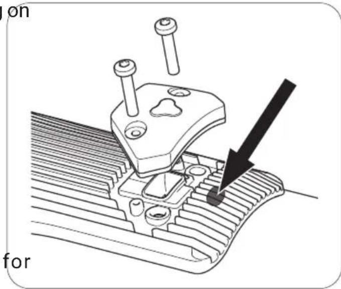
An electric bicycle has hidden wiring through frame and has other critical electric bicycle parts like the drive unit and battery pack. When mounting accessories (e.g. a bottle cage), be sure not to impact the wiring or battery pack, e.g. by using too long or pointed bolts. This might cause a short circuit to the electric system and/or damage to the battery.
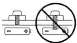
natural_image
Diagram showing two bolted components with a prohibition symbol (no text or labels)7. Visit your dealer on a regular basis for maintenance of your new electric bicycle.
- To guarantee the safe and proper functioning of the bicycle, the bicycle must be maintained on a regular basis, at least once a year, by an authorized electric bicycle dealer.
- Your dealer has the right knowledge and equipment to maintain your electric bicycle and to mount accessories safely.
- If you have questions about your new electric bicycle, ask your dealer!
Compliance
Your bicycle has been designed, tested, and produced in accordance with the applicable European Directives and Harmonised Standards. Therefore, all electric bicycles are in compliance with CE.
For more detailed compliance information, please refer to the Declaration of Conformity (DoC) which was included along with your bicycle. If you have misplaced your DoC, a new one can be furnished upon request, by the bicycle shop at which you purchased your electric bicycle.
Limited warranty
Your bicycle is covered by a Lifetime Limited Warranty.
Please visit our web site for details.
natural_image
Diagram showing a screw fastener with a prohibition symbol (no text or labels)natural_image
Diagram showing two bolted components with a diagonal line and a crossed-out screw, no text or symbols present.natural_image
Diagram showing two bolted components with a crossed-out circle and diagonal line (no text or symbols)natural_image
Technical line drawings of various electronic devices including a push device, battery pack, and display unit (no text or symbols present)Drive system: BASICS
1 Overview: Drive system....6
2 About these instructions....8
2.1 Terms and structure....8
2.2 Reading and retaining the instructions....9
2.3 Explanation of characters & symbols used....9
3 Safety....10
3.1 Functional principle & proper use....10
3.2 Symbols & pictograms of the drive system....11
3.3 General safety instructions....12
3.4 Instructions for safe riding in road traffic 20
4 Use....21
4.1 Inserting and removing components....21
4.2 Switching the drive system on and off....24
4.3 Instructions for driving with the drive system 25
4.4 Switching on the drive system following a standstill......26
4.5 Setting the support level 27
4.6 Using "Pushing support" mode 28
4.7 Charging the battery....29
5 Storage and transport 30
6 Optional accessories....31
7 Cleaning and maintenance....32
8 Troubleshooting....34
9 Disposal instructions ....36
9.1 Disposing of your e-bike....36
9.2 Disposing of the battery....36
10 Manufacturer's warranty, EU 37
11 Service....38
12 EU Conformity....39
Component: DRIVEPACK
13 Detailed view & part designations: Drivepack 40
14 Technical data....42
15 Using the drivepack....42
15.1 Inserting the drivepack into the e-bike....42
15.2 Removing the drivepack from the e-bike 44
15.3 Securing/locking the drivepack on the e-bike....45
Component: BOTTOM BRACKET
16 Detailed view & part designations: Bottom Bracket ....46
17 Technical data....47
18 Using the bottom bracket 47
18.1 Correct position/alignment 48
18.2 Correcting incorrect position/alignment....48
Component: REMOTE
19 Model variants of the remote....50
20 Detailed view & part designations: Remote b....50
21 Technical data on Remote b 52
22 Displays on the remote b....52
22.1 Status display ....52
22.2 Display of charge level/support level....53
23 Using Remote b....54
23.1 Switching the drive system on and off....54
23.2 Setting the pedal support ....55
23.3 Support levels....55
23.4 "Pushing support" mode....56
24 Detailed view & part designations: Remote fX and Remote bX .....58
25 Technical data for Remote fX and Remote bX 59
26 Displays on Remote fX and Remote bX 59
26.1 Status display 60
26.2 Display of charge level/support level 60
27 Using the Remote fX and Remote bX....61
27.1 Switching the drive system on and off....61
27.2 Setting the pedal support level....62
27.3 Support levels....63
27.4 Re-starting the drive system....64
27.5 Rain mode....64
27.6 Switching the bicycle lighting on and off....65
27.7 Bluetooth® connection....65
Component: BATTERY
28 Model variants of the battery....66
29 Detailed view & part designations: Battery 67
30 Technical data....68
31 Using the battery....68
31.1 Checking and switching on battery....68
31.2 Inserting the battery into the drivepack....69
31.3 Removing the battery from the drivepack ....71
31.4 Switching off the battery....71
31.5 Charging the battery....72
31.6 Charging process 73
31.7 Battery charge level indicator....74
Component: CHARGER
32 Model variants of the charger....75
33 Detailed view & part designations: Charger....75
34 Technical data....76
35 Using the charger....77
35.1 Preparing the charger....77
35.2 Connector charger to the battery 78
35.3 Unplugging the charger from the battery 79
A
Drivepack
(Details from page EN-40)

natural_image
Technical line drawing of a mechanical component with curved and straight sections (no text or symbols)B
Bottom Bracket
(Details from page EN-46)
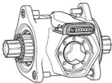
natural_image
Technical line drawing of a mechanical assembly with gears and housing (no text or symbols)C
Remote
(Details from page EN-50)
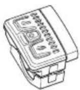
Remote b

Remote fX

Remote bX
D
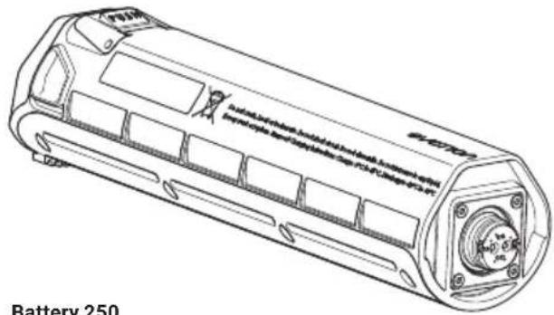
Battery
(Details from page EN-66)
natural_image
Technical line drawing of a battery with internal components and mounting holes (no text or symbols)
natural_image
Technical line drawing of a cylindrical battery with mounting flanges and internal components (no text or symbols)Battery 250 X
E
Charger
(Details from page EN-75)
Charger A Charger S (EU/US)
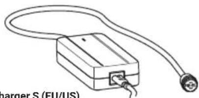
natural_image
Line drawing of a charger S (EU/US) connected to a cable and terminal connector (no text or symbols on the diagram itself)
natural_image
Simple line drawing of a rectangular device connected to a terminal outlet (no text or symbols)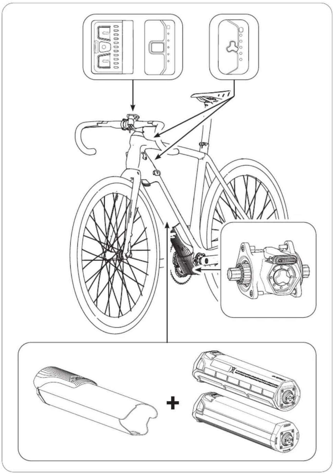
text_image
Diagram illustrating bicycle wheel assembly and battery pack installation, with labeled components and assembly steps.2 ABOUT THESE INSTRUCTIONS
2.1 Terms and structure
These original operating instructions form part of the Fazua drive system, evation.
To improve readability, the term "Instructions" will be used below instead of the term "Original operating instructions". The decision to use the masculine form (e.g. the user) throughout the text is also based exclusively on improving readability. We ask for your understanding for this simplification; the instructions are of course intended for all genders.
To facilitate orientation within these instructions, it is divided into sections: The first section, "Basics", covers the drive system as a whole. Chapter 3 "Safety" contains the basic information on proper use and the general safety instructions. Chapters 4–8 ("Use", "Storage and transport", "Optional accessories", "Cleaning and maintenance", "Troubleshooting") describe procedures and actions to be carried out. Chapters 9–12 provide information on disposal, the manufacturer's warranty, services from the manufacturer or dealer, and on EU conformity.
These sections are dedicated respectively to the individual components of the drive system. Here you will find detailed illustrations and additional or more in-depth information on the component in question. In addition, the action steps outlined in chapter 4 "Use" are described in detail, with warning notices on the specific steps.
2.2 Reading and retaining the instructions
These instructions contain all important information on safety and the use of the drive system as well as on the individual components. It is based on the standards and regulations valid in the European Union.
It is essential to read through the complete instructions carefully – in particular the "Safety" chapter – before using the drive system for the first time. If you do not observe the instructions, you or other persons may suffer serious injuries and/or the drive system or individual components may be damaged.
Keep these instructions to hand at all times for ongoing use, and include these instructions if you pass on the drive system or an e-bike equipped with the drive system.
In addition to these instructions, it is also essential to observe the manufacturer's instructions on the e-bike in which the drive system is installed.
2.3 Explanation of characters & symbols used
Certain types of notices and information in these instructions are marked by characters or symbols that are listed below, including their meanings.
WARNING
Risks that could result in death or serious injury are identified with the signal word, "Warning".
CAUTION
Risks that could result in moderate or minor injuries are identified with the signal word, "Caution".
NOTICE
Risks relating to damage to the product itself or to property damage to other objects, are identified with the "Notice" signal word.

Useful additional information is identified with this information symbol.
3 SAFETY
3.1 Functional principle & proper use
evation is designed as an electric drive system for e-bikes used as a means of transport for one person. From a speed of 25 km/h, the electric pedal support switches off so that at speeds over 25 km/h without motor support, you pedal solely with your own muscle power.
The drive system as a whole comprises a variety of coordinated components operating together.
These are:
A → Drivepack
[incl. locker for locking to the frame],
B → Bottom Bracket
[incl. speed sensor + spoke magnet],
C → Remote
[models: Remote b, Remote fX, Remote bX],
D → Battery
[models: Battery 250, Battery 250 X],
E → Charger
[models: Charger A, Charger S (EU/US)].
The version of the drive system installed in your e-bike, in other words the specific combination of component versions, is designed specifically for your e-bike and cannot therefore be changed. The basic principle is that the installation of the drive system as well as specific work on the system are only permitted to be carried out via the routes specified by the manufacturer or by an authorised specialist. Information on which works you are able to carry out and which works need to be performed by an authorised specialist can be found in the separate sections on the individual components.
Fazua accepts no liability for damage caused by incorrect or improper installation or unintended usage. Only use the drive system as described in these instructions. Any other usage is regarded as unintended and can result in accidents, serious personal injury and damage to the drive system.
3.2 Symbols & pictograms of the drive system
On individual components of the drive system, you will find specific symbols and pictograms which are listed along with their meanings.

This symbol indicates that the user of the drive system or the individual components must read and understand these original instructions before use.
Any devices identified with this symbol (in this case, the charger) may only be used in dry indoor areas.
WARNING! When using in damp environments and on contact with liquids, there is a risk of electric shock!

An electrical device marked with this symbol corresponds to protection class II: The device has double or reinforced insulation as protection against electric shock.
This symbol is a warning against hot surfaces.
WARNING! There is a risk of burns on contact, and a risk of fire on contact with flammable materials.
These symbols indicate that the battery (lithium-ion rechargeable battery) must be disposed of separately at the end of its service life and must not be disposed of with household waste.

For specific information, see the "Disposal" chapter.
This symbol indicates that the component marked with this symbol must be disposed of separately as electrical or electronic equipment at the end of its service life and must not be disposed of with household waste.
For specific information, see the "Disposal" chapter.

This symbol indicates products that meet all requirements for obtaining the European CE marking.
Specific information can be found in the "EU Conformity" chapter.
 | The "Geprüfte Sicherheit" (GS mark) seal of approval is awarded by independent certification bodies.A device marked with the GS test seal complies with the safety-relevant requirements of the German Product Safety Act (Produktsicherheitsgesetz; ProdSG). |
| CULUSLISTED | The "UL®-Listed" test seal is awarded by the US certification body, UL®.A device marked with the "UL®-Listed" test seal shown here complies with the safety-relevant requirements for Canada and the USA. |
 | The FCC Seal is issued by the "Federal Communications Commission", an independent U.S. government agency responsible for implementing and enforcing U.S. communications laws and regulations.An electrical device bearing the FCC seal complies with U.S. electromagnetic compatibility requirements. |
3.3 General safety instructions
The general safety instructions given below are to be observed at all times when using and handling the drive system.
WARNING
Dangers to e-bike users!
There are fundamentally specific dangers to users of e-bikes. Depending on the e-bike model into which the drive system is installed, additional dangers may arise that are not covered here.
▶ Read and follow the manufacturer's instructions for your e-bike.
▶ Obtain information on any relevant national standards relating to e-bikes and comply with these.
WARNING
Dangers due to unauthorised modifications!
If you carry out unauthorised modifications to the drive system or to the components, you may cause an explosion, suffer an electric shock or cause serious injury to yourself or others.
▶ Never make any unauthorised modifications or changes to individual components of the drive system.
▶ Do not perform any unauthorised replacement of the drive system components.
▶ Never open any components of the drive system without authorisation. The components of the drive system do not require any maintenance. Only allow repairs to the drive system to be performed by authorised specialists.
▶ Only allow the components of the drive system to be replaced by an authorised specialist and with genuine spare parts.
WARNING
Danger due to accidental start-up!
If the drive system is put into operation in inappropriate situations, this can result in accidents and serious injuries.
Remove the drivepack from the e-bike while transporting or storing the e-bike, and during all work on the e-bike, to avoid the drive system being started up accidentally.
▶ Only use the "Pushing support" function when pushing the e-bike. While pushing support is activated, you must hold the e-bike securely with both hands and the wheels must be in contact with the ground, otherwise there is a risk of injury.
WARNING
Danger of battery explosion!
The battery may explode if you use inappropriate batteries or do not handle the rechargeable battery correctly.
▶ Only use the genuine battery from Fazua approved by the e-bike manufacturer.
▶ Under no circumstances use a damaged battery and never attempt to charge a damaged battery!
▶ Never open up the battery! There is an increased risk of explosion if you attempt to open a battery!
▶ Keep the battery away from heat (e.g. strong sunlight), naked flame or water and other fluids.
▶ Only use the battery in e-bikes equipped with an original Fazua evation drive system. Never use the battery for other purposes or in other drive systems.
WARNING
Fire hazard due to incorrect handling!
If you handle the battery and/or charger improperly or use incompatible batteries and chargers together, you may cause a fire.
▶ To charge the battery, use only original and compatible evation chargers from Fazua.
▶ Take care not to handle metal objects such as coins, paper clips, screws, etc. in the immediate vicinity of the battery and store the battery separately from metal objects. Metal objects can create a circuit between the terminals of the battery (= rechargeable battery) (i.e. "short-circuit" the battery) and thus cause a fire.
▶ Never short-circuit the battery.
The battery and charger can heat up during the charging process or during operation. It is therefore essential to keep the battery and charger away from flammable materials. Take particular care on this point during the charging process, and move the battery and charger to a dry and fire-proof location before charging.
▶ Never leave the battery and charger unattended during charging.
WARNING
Danger of chemical burns from battery acid!
The battery contains battery acid. If you come into contact with this liquid, the affected area of skin and/or mucous membranes may suffer chemical burns. Loss of sight is possible on contact with the eyes.
▶ Never touch any liquid leaking from the battery.
▶ If you come into contact with battery acid, rinse the affected body part thoroughly under running water straight away.
▶ After rinsing, seek advice from a doctor immediately, in particular on eye contact and/or if the mucous membranes are affected (e.g. nasal mucous membranes).
WARNING
Health risk due to irritation of the airways!
If the battery is damaged, gases may escape that can result in irritation of the airways.
▶ Protect the battery from mechanical impact and any other type of load.
▶ If you notice or suspect that gas is escaping from the battery, immediately ensure that there is a fresh supply of air and consult a doctor as soon as possible.
WARNING
Danger of interference with medical equipment!
The magnetic connections of the battery (= rechargeable battery) and charger can impair the function of pacemakers.
▶ Keep the battery and the charger away from pacemakers or persons with pacemakers and make people with pacemakers aware of the danger.
WARNING
Risk of electric shock!
Improper handling of the charger or incorrect mains connection may expose you and others to the risk of electric shock.
▶ Only connect the charger to an easily accessible and properly installed earth contact outlet.
▶ Make sure that the mains voltage at the mains connection corresponds to the information on the charger.
▶ Only use the charger in dry indoor areas.
▶ Keep the charger away from all liquids and humidity.
▶ Do not pull on the mains cable or charging cable to remove the respective cable from a socket or outlet, and instead always grip the corresponding plug.
▶ Never touch the plugs on the mains cable or charging cable with wet or damp hands.
▶ Take care not to bend the mains cable and charger cable or place them over sharp edges.
▶ Do not open the charger yourself. The charger may only be opened by an authorised specialist and may only be repaired with genuine spare parts.
Before each use of the charger, check all individual parts (mains adapter, mains cable, charging cable and all plugs) for damage. If the charger's mains cable is damaged, it must be replaced by the manufacturer, its customer service department or a similarly qualified person to avoid any dangers.
▶ Never use a damaged charger. Otherwise, there is a high risk of electric shock!
▶ Keep the charger in a clean condition. There is an increased risk of electric shock if the charger is dirty or soiled.
WARNING
Dangers due to unauthorised usage!
If, for example, children or persons who are physically or mentally handicapped handle the battery or charger, there is an increased risk potential, as these user groups may not be able to correctly assess certain risks.
The charger may not be used by children or persons with limited physical, sensory or mental abilities unless they are supervised or have been instructed in the safe use of the charger and have understood the resulting dangers.
▶ Children are not permitted to not play with the charger.
▶ Cleaning and user maintenance must not be carried out by children without supervision.
▶ Keep the battery and the charger out of the reach of children.
CAUTION
Risk of burns!
The radiator in the drivepack can become very hot during operation, meaning you may burn yourself.
▶ Proceed with caution when handling the drivepack.
▶ Allow the drivepack to cool down completely before touching the drivepack.
NOTICE
Danger of damage!
Improper handling can damage the drive system or individual components.
▶ Have individual components of the drive system and the e-bike replaced only with identical or other components expressly approved by the e-bike manufacturer. In this way, you protect the other components or your e-bike from possible damage.
▶ Never use your e-bike without an inserted drivepack or cover when using the e-bike as a conventional bicycle without drivepack.
Remove the battery before cleaning the drivepack and allow all components to dry completely before inserting them. The battery can be damaged if the battery comes into contact with wet or damp drivepack contacts during insertion.
When charging the battery, make sure that the charger's mains cable and charging cable do not present a trip hazard to avoid damaging components as a result of a fall, for example.
3.4 Instructions for safe riding in road traffic
By following the instructions listed below for safe riding in road traffic, you can reduce the risk of accidents and injuries when riding a bicycle or e-bike.

The term "road traffic" also refers to publicly accessible private areas and publicly accessible field or forest paths.
▶ Only ride your e-bike in road traffic if the equipment complies with national road traffic regulations. If appropriate, ask your e-bike manufacturer for further information.
▶ Find out about the applicable road traffic regulations of the country or region, including for example, from the Ministry of Transport. Always keep yourself informed regarding changes in the content of the valid regulations.
▶ Observe and follow the country-specific and regional road traffic regulations.
When riding, use a suitable bicycle helmet that complies with the country-specific and regional regulations or that is tested according to the DIN EN 1078 standard and bears the CE mark.
▶ When riding, wear light-coloured clothing with reflective elements to attract the attention of other road users.
▶ Do not ride your e-bike if you are under the influence of alcohol, intoxicants or medication that could impair your ability to ride safely.
▶ Do not use mobile devices such as smartphones, MP3 players or similar while riding.
▶ Do not distract yourself with other activities while riding, such as turning on lights. Stop first to carry out these types of activities.
▶ Never drive with your hands off the handlebars. Always keep both hands on the handlebars.
▶ Ride carefully and show consideration for other road users.
▶ Ride in such a way that no-one is injured, endangered, hindered or harassed.
▶ Ride on prescribed lanes for bicycles, where available.
4 USE
This chapter describes chronologically how to proceed when using the drive system.
It is essential that you also read the detailed descriptions in the section relating to the component in question:
- before you use your e-bike equipped with the evation drive system for the first time,
• if you are unsure how to use it, - if you have problems performing the steps as described here.
4.1 Inserting and removing components
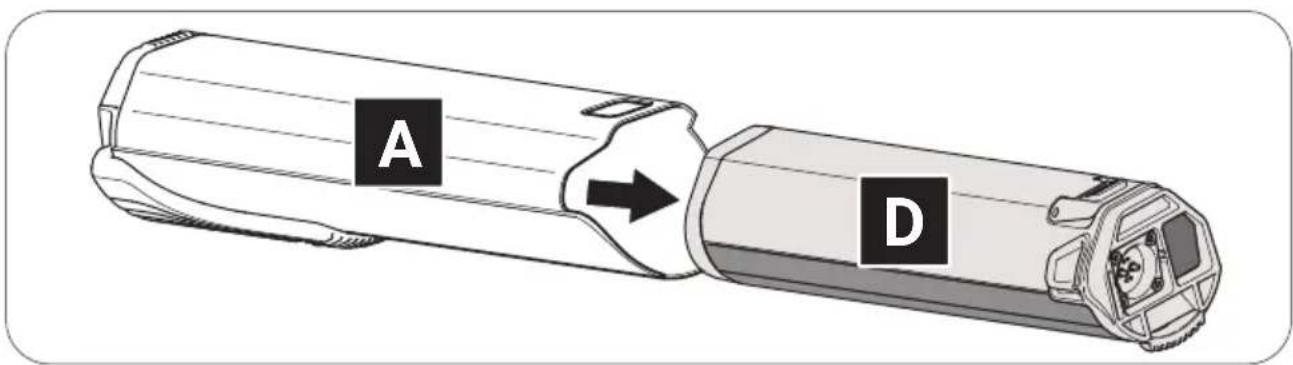
4.1.1 Inserting the battery into the drivepack
→ More detailed information can be found in chapter 31.1 "Checking and switching on battery" and in chapter 31.2 "Inserting the battery into the drivepack".

On delivery, the battery may only be pre-charged.
▶ Fully charge the battery before inserting it into the drive-pack for the first time.
- Check the battery for visible damage.
- Press the power button on the battery once to turn the battery on.
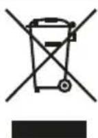
- Attach the battery to the battery compartment of the drivepack with the connector contact first.
text_image
A D- Carefully insert the battery fully into the battery holder.
The battery will lock automatically if you insert it correctly. If the battery does not lock, repeat the procedure. Do not use the drive system if the battery cannot be locked in position.
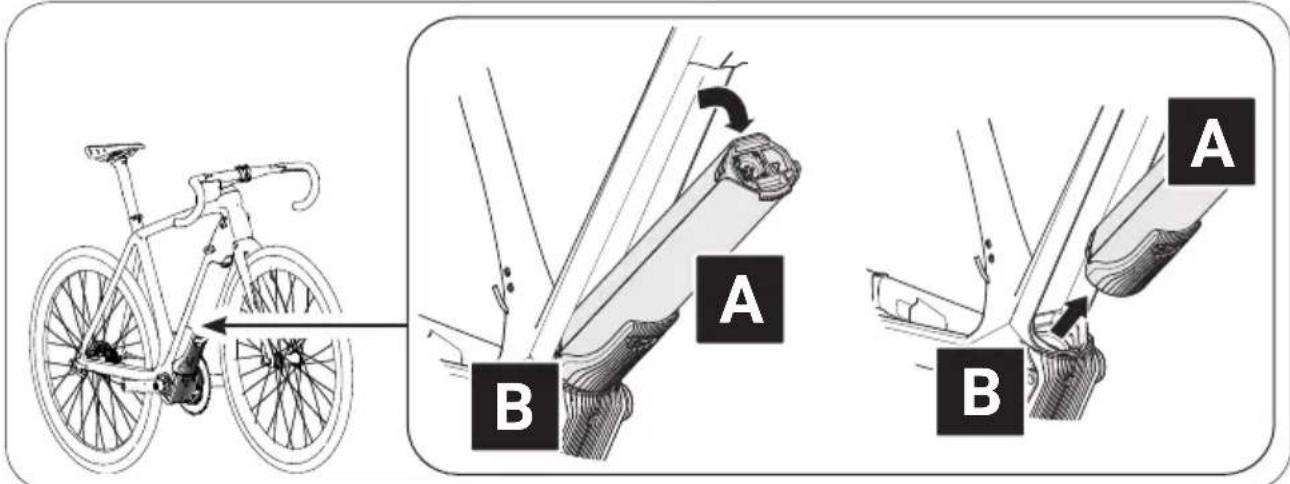
4.1.2 Inserting the drivepack into the e-bike
→ More detailed information can be found in chapter 15.1 "Inserting the drivepack into the e-bike".
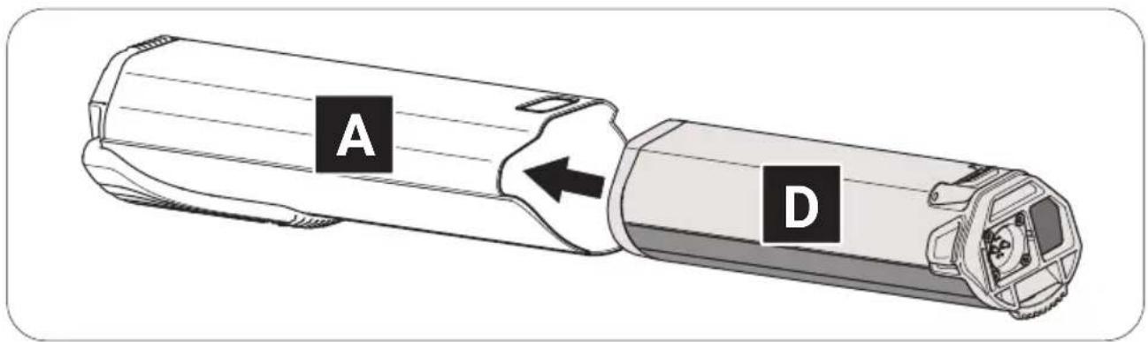
- Position the drivepack with the interface for the bottom bracket onto the corresponding interface on the bottom bracket.
- Swing the upper end of the drivepack into the downtube of the e-bike. The drivepack is automatically locked in place when the two interfaces on the drivepack and bottom bracket are correctly interlocked and the drivepack is completely swivelled into the corresponding mount on the downtube.
text_image
Diagram illustrating bicycle wheel positioning and joint movement, labeled A and B with directional arrows and structural details.- Check that the drivepack is securely fitted.
If the drivepack does not lock, repeat the procedure. Do not use the drive system if the drivepack cannot be locked to the e-bike.
4.1.3 Removing the drivepack from the e-bike
→ More detailed information can be found in chapter 15.2 "Removing the drivepack from the e-bike".
- Secure the drivepack with one hand.
- Press the push button and move the locking lever upwards as far as possible to release the drivepack from the lock.
- Hold down the push button and carefully lower the drivepack. The locking lever automatically remains in the open position.
- Remove the drivepack from the interface of the bottom bracket.
text_image
Diagram illustrating bicycle seat positioning and movement, labeled A and B with directional arrows and foot movements.4.1.4 Removing the battery from the drivepack
→ More detailed information can be found in chapter 31.3 "Removing the battery from the drivepack".
- Secure the battery with one hand.
- Press the push button as far as it will go to release the battery from the lock.
- Press and hold the push button and gently pull the battery out of the battery holder.
text_image
A D4.2 Switching the drive system on and off

Appearance and handling of the model-dependent remotes have slight differences.
→ More detailed information can be found in chapter 19 "Model variants of the remote".
For all the details listed here, please note exactly those that apply to your remote. If none of the model variants is explicitly mentioned, the descriptions refer to all remotes.
4.2.1 Switching on the drive system
→ More detailed information can be found in chapter 23.1 "Switching the drive system on and off" or in chapter 27.1 "Switching the drive system on and off".
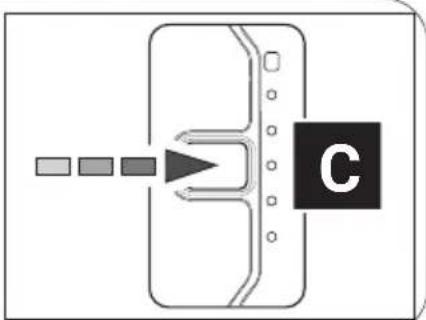
▶ Switch on the drive system using Remote b by pressing one of the three buttons.
or
▶ Switch on the drive system using Remote fX or Remote bX by pressing the centre button.
flowchart
graph TD
    A["Input Stage 1"] --> B["Process Unit"]
    C["Input Stage 2"] --> B
    D["Input Stage 3"] --> B
    E["Input Stage 4"] --> B
    B --> F["C"]
flowchart
graph TD
    A["Start"] --> B{Decision}
    B --> C["Label C"]
flowchart
graph TD
    A["Input"] --> B{Decision}
    B --> C["C"]
4.2.2 Switching off the drive system
→ More detailed information can be found in chapter 23.1 "Switching the drive system on and off" or in chapter 27.1 "Switching the drive system on and off" as well as in chapter 4.4 "Switching on the drive system following a standstill".
You can switch off the drive system in different ways:
▶ Hold down the centre button on remote 2 (Remote b) or 1 second (Remote fX and Remote bX) to switch off the drive system.
or
▶ Remove the drivepack from your e-bike.
or
▶ Switch off the battery by pressing and holding the on/off button.

Fazua recommends switching off the battery in addition to the drive system if you park your e-bike for an extended period of time (e.g. if you take a break during a longer trip).
→ More detailed information can be found in chapter 31.4 "Switching off the battery"
4.3 Instructions for driving with the drive system
Follow these instructions for riding your e-bike equipped with the evation drive system.
Changing gear:
The gears of your e-bike are to be operated in the same way as those of a conventional bicycle. By selecting a suitable gear, the speed, power and range of your e-bike will increase while maintaining the same cadence.
The following points apply regardless of the type of gears fitted:
▶ Stop pedalling when you change gear. This relieves the derailleur mechanism and the drive of your e-bike.
Range/route planning:
How long or far you can ride your e-bike before you have to recharge the battery depends on several factors.
These factors include, for example:
• The set support level;
• The (riding) speed at which you move forwards;
• The way in which you change gear;
• The type of tyres and the set tyre pressure;
• The selected route and weather conditions;
• The weight of the rider and the e-bike (total weight);
• The condition and age of the battery.
The following general principles apply:
▶ Familiarise yourself with your e-bike step by step and stay away from roads and heavy traffic initially.
▶ Test the maximum range of your e-bike under various outdoor conditions before planning longer trips. An exact statement regarding the range of your system is not possible before or during a trip.
Storage and operating temperatures
▶ Observe the operating and storage temperatures for the components of the drive system and for the components of your e-bike, and in particular those for the battery, as it can be damaged by extreme temperatures.
4.4 Switching on the drive system following a standstill

Your e-bike will be at a standstill as soon as it is switched off.
• After 15 minutes of standstill, the drive system (not the battery!) switches off automatically.
The drive system can be switched on again using the remote by briefly pressing the centre button.
• After 8 hours of standstill (provided no button/touch sensor is pressed during this time), the battery switches off.
- After 3 hours of standstill (provided the battery charge level is below 30% and no button/touch sensor is pressed during this time), the battery switches off.
▶ Switch on Battery 250 and Battery 250 X by pressing the on/off button to be able to use the drive system again after the battery has automatically shut down due to a standstill.
4.5 Setting the support level
→ More detailed information can be found in chapter 23.2 "Setting the pedal support" or in chapter 27.2 "Setting the pedal support level" as well as in chapter 23.3 "Support levels" or in chapter 27.3 "Support levels".
The remote can be used at any time to set the desired support level, including when riding.
▶ Press the top button/top touch sensor to switch to the next higher support level.
▶ Press the button/bottom touch sensor to switch to the next lower support level.
| "SUPPORT LEVELS" OVERVIEW TABLE | ||
| Support level Colour Max. motor power | ||
| none white 0 | W | |
| Breeze | green | 400 W* |
| River | blue | 400 W* |
| Rocket | pink | 400 W* |
* The values given here are the "theoretical" maximum motor power. The "actual" maximum motor power is configured by the manufacturer of your e-bike, depending on the model.
4.6 Using "Pushing support" mode

If your e-bike is equipped with a Remote b, it will have the "Pushing support" mode that you can use when pushing your e-bike.
→ More detailed information can be found in chapter 23.4 ""Pushing support" mode".
WARNING
Danger due to accidental start-up!
If the drive system is put into operation in inappropriate situations, this can result in accidents and serious injuries.
▶ Only use the "Pushing support" function when pushing the e-bike.
▶ Hold the e-bike securely with both hands when pushing support is active, and ensure that the wheels are in contact with the ground.
CAUTION
Risk of injury!
If you are pushing the e-bike with pushing support activated, the pedals will also turn slowly and you could be injured on them.
▶ Make sure you do not injure yourself on the rotating pedals when using the "Pushing support" function.
-
Change to the support level "none" where appropriate.
-
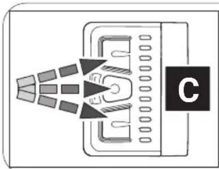
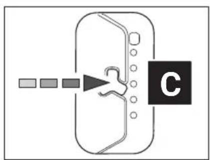
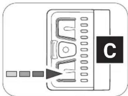
Press and hold down the bottom button on remote b to activate "Pushing support" mode.
natural_image
Diagram of a device with a labeled component 'C' and directional arrow pointing to its screen (no text or symbols beyond label)After 2 seconds, the pushing support is activated and sets the e-bike in motion as long as you keep the button pressed.
-
Guide the e-bike with both hands and brake as necessary to adjust the speed of the e-bike to your own walking pace by holding or restraining the e-bike while pushing.
-
Switch off the pushing support by releasing the bottom button.
4.7 Charging the battery

You can either leave the battery in the drivepack during charging or remove it from the drivepack and charge it separately.
- Before charging the battery, prepare the charger by connecting the mains cable to the mains adapter.
→ More detailed information can be found in chapter 35.1 "Preparing the charger".
- Remove the drivepack from your e-bike.
→ More detailed information can be found in chapter 15.2 "Removing the drivepack from the e-bike".
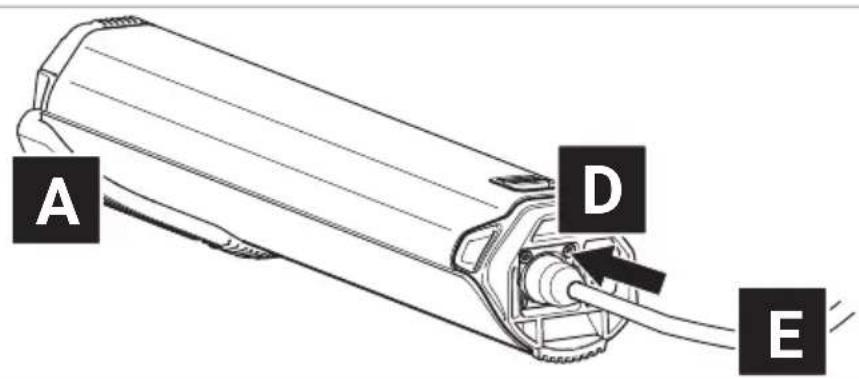
- Insert the charging plug into the charging socket on the battery.
→ More detailed information can be found in chapter 35.2 "Connector charger to the battery".
text_image
A D E- Plug the power plug into a suitable wall outlet to establish the power connection.
The charging process starts automatically after connection to the mains.
→ More detailed information can be found in chapter 31.6 "Charging process" and in chapter 31.7 "Battery charge level indicator".
-
Disconnect the charger from the mains by unplugging the mains plug from the socket when charging is complete or to interrupt charging.
-
Disconnect the charger from the battery by pulling the charger plug out of the charging socket on the battery.
→ More detailed information can be found in chapter 35.3 "Unplugging the charger from the battery".
5 STORAGE AND TRANSPORT
WARNING
Danger due to accidental start-up!
If the drive system is put into operation in inappropriate situations, this can result in accidents and serious injuries.
▶ Always remove the drivepack with the battery before transporting your e-bike or stowing/storing it for an extended period of time.
When transporting and storing your e-bike or the components of the drive system, please observe the specified temperature ranges for the components.
▶ Always transport and store the battery (= rechargeable battery) separately from the e-bike.
Batteries are subject to hazardous goods regulations. Undamaged batteries may be transported by private persons in road traffic. Commercial transport requires compliance with the regulations on the packaging, labelling and transport of hazardous goods. Open contacts must be covered and the battery securely packed. When shipping, the parcel service must be notified of the presence of hazardous goods in the packaging.
▶ Please note the following information on the charge level of the battery when it is not used for an extended period of time and the information on the temperature ranges for the corresponding storage periods.
The battery should have a charge level of at least 60% if you plan not to use it for an extended period of time.
Check the battery charge level after 6 months of non-use: If the check shows that the charge level is 20% or less, recharge the battery to at least 60% charge level.
Observe the following storage time dependent temperature ranges for the battery (60% charge level):
• < 1 month storage time: -15 to 60 °C
• 3 month storage time: -15 to 45 °C
• 1 year storage time: -15 to 25 °C
▶ If you have any questions, please contact a Fazua Servicepartner or visit the official Fazua service platform (www.fazua.com/help).
6 OPTIONAL ACCESSORIES
Downtube Cover
NOTICE
Danger of damage!
Components of the drive system may be damaged if you use the e-bike or bicycle without the drivepack inserted and the opening for the drivepack on the downtube of the frame remains unlocked.
If using the e-bike as a conventional bike without the drive-pack, close the drivepack opening on the downtube of the frame using the optional downtube cover.
You can easily use your e-bike as a conventional bike without an electric drive system by removing the drivepack.
Using the optional downtube cover, you can cover the free opening on the downtube after removing the drivepack. The remaining interior space can be used as storage space for repair kit, tools or food.
▶ If you have any questions on the optional downtube cover, please contact a Fazua Servicepartner or visit the official Fazua service platform (www.fazua.com/help).
Fazua Rider app by CoModule:
Depending on the model, your remote is equipped with Bluetooth® functionality. This allows you to connect a mobile device (e.g. your smartphone) to the remote and use the Fazua Rider app to display and evaluate certain trip data etc.
▶ If you have any questions about the Fazua Rider app, please contact a Fazua Servicepartner or visit the official Fazua service platform (www.fazua.com/help).
All remotes with the serial number 1805113000 or higher are Bluetooth® compatible ex works.
▶ Contact a Fazua Servicepartner if the remote you have installed is not Bluetooth®-enabled.
7 CLEANING AND MAINTENANCE
CAUTION
Risk of injury!
If the drive system is started up while you are working on it, you may get your fingers caught or otherwise injure yourself.
Remove the drivepack from the e-bike when cleaning the e-bike or the components of the drive system.
NOTICE
Danger of damage!
Improper cleaning can damage the drive system or individual components.
▶ Never immerse the components of the drive system in water or other liquids for cleaning.
▶ Do not use any aggressive cleaning agents when cleaning.
▶ Do not use any sharp, angular or metallic objects for cleaning.
▶ Never clean the components of the drive system with a hard water jet or a high-pressure cleaner.
▶ Always keep all components of the e-bike and drive system in a clean condition.
▶ Clean the components gently with a cloth or soft brush.
▶ After cleaning, wipe all surfaces and components to dry them.
▶ Pay particular attention to the contacts and interfaces between the battery and the drivepack, and between the drivepack and the bottom bracket: The interfaces must not be soiled or contaminated and must be completely dry before inserting the components to avoid damage.
▶ Clean the radiator of the drivepack regularly.
Do not clean the radiator until it is visibly or heavily soiled!
▶ Keep the drainage opening on
the radiator clean and clear to ensure that splash water and/or condensation can drain off the drivepack without any problems. The drainage opening is located on the cooling unit directly above the USB port or the corresponding cover (see figure on the right).
text_image
on for▶ Lubricate the locker locking the drivepack to the
frame about every 2–3 months or at the latest as soon as it can no longer be easily operated.
▶ If you have any questions about cleaning and maintenance of your drive system, please contact a Fazua Servicepartner or visit the official Fazua service platform (www.fazua.com/help).
8 TROUBLESHOOTING
- If your e-bike or the drive system does not function as desired, first check whether the fault can be rectified using the "Troubleshooting" overview table given below.
-
Where appropriate, please contact a Fazua Servicepartner or visit the official Fazua service platform (www.fazua.com/help) in the following cases:
-
The fault is not listed in the overview table,
- The fault is listed in the overview table, but it is not resolved by following the instructions provided here, or if you are unsure.
| "TROUBLESHOOTING" OVERVIEW TABLE | |
| Problem possible cause / solution | |
| Motor power feels lower than usual. | The drive system is brand new.► Wait until the drive system is "retracted". The drive system requires a few kilometres to produce full power |
| It is very hot and the heat management of the battery and/or drivepack limits the performance. | |
| It is very cold, meaning the battery (= lithium-ion battery) is not providing the usual performance level. | |
| The drivepack cannot be clicked out of the down-tube. | The locker is defective.Dirt could be blocking the locker. It may be that you have ridden without the drivepack in bad weather conditions.► Contact a Fazua Servicepartner. |
| The drivepack is making buzzing noises. | The polygon sleeve is moving.► Contact a Fazua Servicepartner. |
| The drivepack is making clicking noises. | The polygon coupling has been loaded on one side.► Push the polygon coupling back into its original position to mobilise it again. |
| The upper LED on the remote will light/flash red. | There is a connection error between the drivepack and bottom bracket.There may be dirt on the interface that is obstructing the connection.► Clean the interface between the bottom bracket and the drivepack. |
| The upper LED on the remote lights up/flashes yellow. | It may be that there is a bad connection between the speed sensor and bottom bracket.► Check the position of the spoke magnet. If you do not find a fault, contact a Fazua Servicepartner. |
| The white LEDs on the remote flash. | Software update► After a new firmware update, the remote will update itself automatically. In this case, please wait and do not switch off the remote until the LEDs stop flashing |
| The remote cannot be switched on. | The battery is empty or has been switched off due to an extended idle period (standstill).► Try turning the battery on using the on/off button.► Charge the battery if necessary. |
| The interface between the battery and the drivepack may be dirty.► Clean the interface between the battery and the drivepack. | |
| The battery cannot be inserted into the drivepack or snapped into the battery holder. | The interface between the battery and the drivepack may be dirty.► Clean the interface between the battery and the drivepack. |
| Sudden lack of support when riding the bike | BMS protective function► Switch off the battery by pressing the on/off button for 3 seconds and then switch it back on again. |
9 DISPOSAL INSTRUCTIONS
According to the EU Directives on waste electrical equipment (Directive 2012/19/EU) and waste accumulators (Directive 2006/66/EC), the corresponding components must be collected separately and disposed of in an environmentally friendly manner.
Before disposing of your e-bike, remove the battery and any other accumulators and batteries installed on the e-bike, as well as all components and control panels containing accumulators or batteries.
9.1 Disposing of your e-bike
After you have removed all accumulators and batteries, the e-bike is considered waste electrical equipment and must be recycled.
▶ Please contact your city or local government (council, region) for information regarding free collection points for waste electrical equipment and/or collection points where the component or e-bike can be recycled.
▶ If necessary, make sure you delete any personal data stored on the device before you return the electrical or electronic device to the collection point. This task is your responsibility.
9.2 Disposing of the battery
The battery of the drive system is a lithium-ion battery that must be disposed of as hazardous waste.
▶ Dispose of the battery of the drive system as well as any other batteries and accumulators installed on the e-bike at a recycling centre or at a collection point in your town or municipality.
10 MANUFACTURER'S WARRANTY, EU
FAZUA GmbH, Marie-Curie-Straße 6, 85521 Ottobrunn, Germany (hereinafter referred to as "Manufacturer") guarantees to the end customer (hereinafter referred to as "Customer") in accordance with the following provisions that the drive system and its components installed in the bicycle (hereinafter referred to as "Product") purchased by the customer within the European Union (as of 01 January 2017) and Switzerland (hereinafter referred to as "geographical scope") is free of design, material and processing faults and will function without restriction for a period of two years following delivery (warranty period).
If, nevertheless, a fault occurs or the drive system is not fully functional, the manufacturer will remedy this at his own discretion and expense by repairing or supplying new or reconditioned parts.
The statutory rights of the customer due to defects according to § 437 of the German Civil Code (Bundesgesetzbuch; BGB) remain unaffected and are not limited by this warranty, but the customer is additionally entitled to the rights from this warranty.
However, claims under this guarantee shall only exist if
- the product shows no damage or signs of wear and tear caused by operation deviating from its normal purpose and the manufacturer's specifications as stated in the user manual are caused by different use,
- the product does not have any features that indicate repairs, opening of a component of the product or other interventions by specialist workshops not authorised by the manufacturer, and
- the serial number has not been removed or rendered illegible.
Claims under this warranty require that the customer, before sending the product, has contacted either the dealer from whom he purchased the bicycle or the manufacturer and given them the opportunity to carry out a telephone fault analysis within a period of eight days.
Claims under the warranty can only be made to the manufacturer on presentation of the original invoice with date of purchase.
Claims under this guarantee can only be made by handing over or sending the product to the manufacturer. The costs of sending in and returning the product shall be borne by the manufacturer. If the manufacturer or the dealer has named a specific freight company to the customer for sending the product and the customer nevertheless uses another freight company, the customer must bear the additional costs incurred in this respect.
This warranty shall apply to the extent and under the conditions set forth above, including the presentation of proof of purchase, even in the event of resale, to any subsequent future owner of the product residing within the territorial scope of this warranty.
This guarantee is subject to the law of the Federal Republic of Germany, unless and insofar as this is contradicted by mandatory consumer protection regulations in the country of the respective customer.
11 SERVICE

If possible, prepare the error screen and all information on the relevant component before contacting a Fazua Service-partner or the Fazua service team.
▶ If you require customer service, please contact a Fazua Servicepartner or contact the Fazua service team.
▶ Where applicable, also visit the Fazua service platform:
www.fazua.com/help.
Here you will find comprehensive contents relating to the topic of "Service" as well as a search function for Fazua Servicepartners in your area.
12 EU CONFORMITY
EU Conformity of the individual components or of the drive system
The individual components or the drive system as a whole complies with all applicable EC provisions of the European Economic Area.
The EU Declaration of Conformity for the drive system can be requested from Fazua.
The EU Declaration of Conformity for the e-bike as a whole (including the drive system) can be requested from the manufacturer of your e-bike.
Special information on the remote with Bluetooth® function
FAZUA GmbH hereby declares that this product conforms to the basic requirements and other relevant regulations of the Radio Equipment Directive 2014/53/EU, R&TTE Directive 1999/5/EC, EMC Directive 2014/30/EU, ErP Directive 2009/125/EC, Low Voltage Directive 2014/35/EC and ROHS Directive 2011/65/EC.
The complete Declaration of Conformity and these instructions can be found online in PDF format at www.fazua.com.
DRIVEPACK
13 DETAILED VIEW & PART DESIGNATIONS: DRIVEPACK
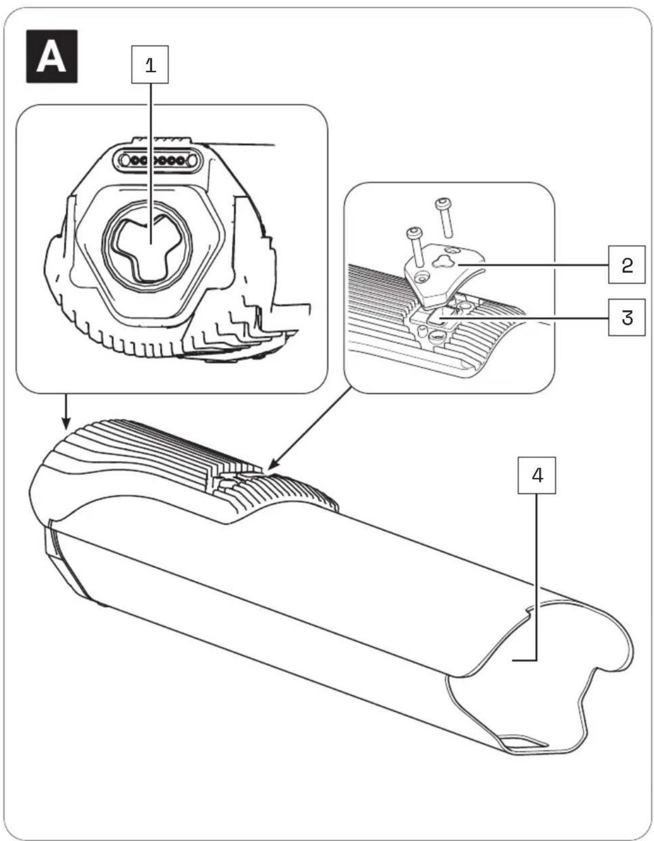
text_image
A 1 2 3 4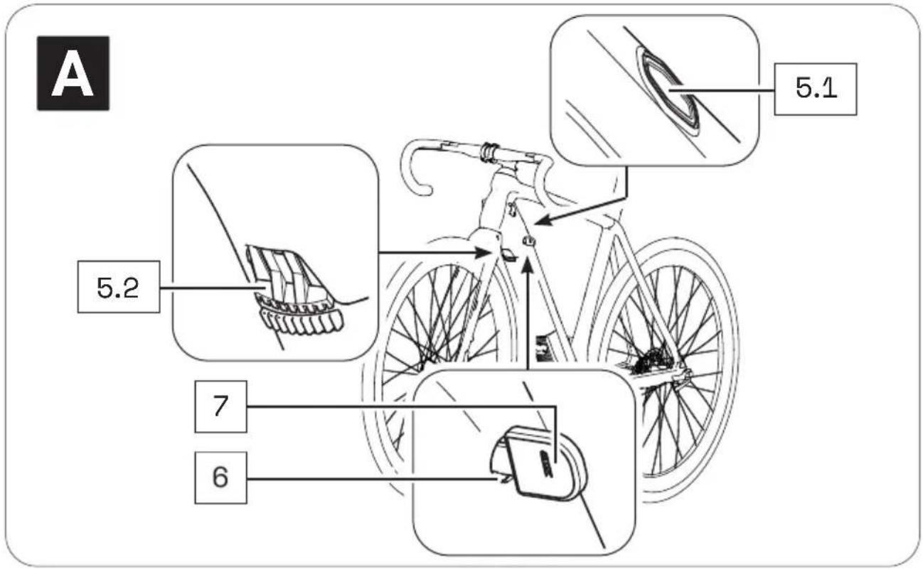
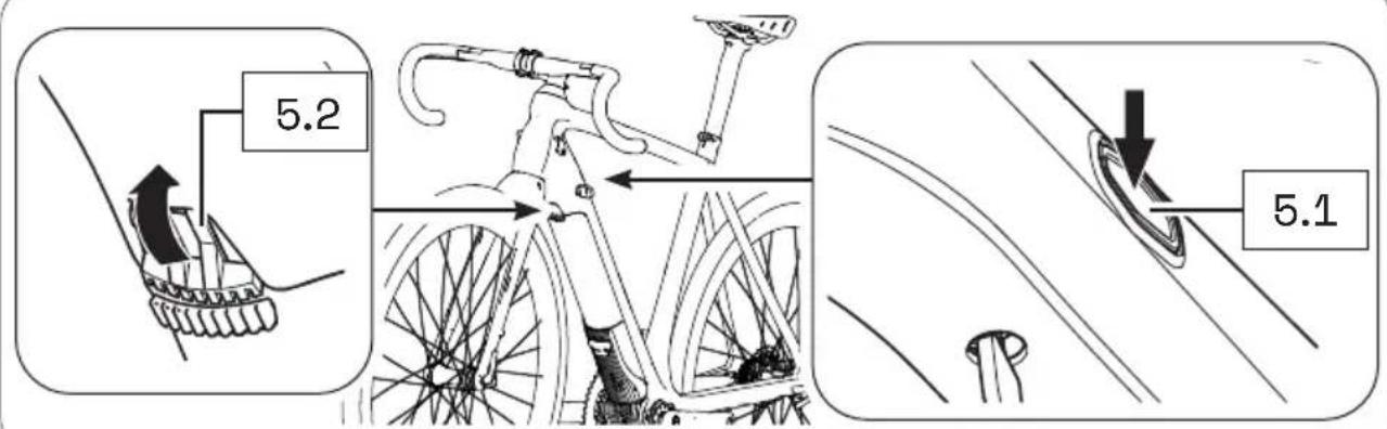
text_image
A 5.2 7 6 5.1Part designations
1 → Interface (bottom bracket)
2 → Cap (USB port)
3 → USB port
4 → Battery holder
5 → Pushbutton (5.1)*/locking lever (5.2)*
6 → Cylinder lock**
7 → Key**
* The locker or mechanism for removing the drivepack is operated differently depending on the model:
With a push button located on the top of the down tube (Locker p) or with a locking lever located on the bottom of the downtube (Locker pX).
In this section you may find different illustrations and descriptions next to each other.
** The cylinder lock (incl. key) is a model-dependent installed part that may not be present on your e-bike.

The numbering 1–7 within this section refers to the individual parts of the component A (drivepack).
Individual parts of other components illustrated within this section are additionally marked with the corresponding component letter.
14 TECHNICAL DATA
| TECHNICAL DATA ON THE DRIVEPACK | |
| Continuous rated power | → 250 W |
| Power, max. | → 400 W |
| Nominal voltage | → 36 V |
| Protection type | → IP54 |
| Weight, approx. | → 1.94 kg |
| Operating temperature | → -5 °C to +40 °C (ambient temperature) |
| Storage temperature (< 1 month) | → -15 °C to +60 °C |
| Storage temperature (> 1 month) | → -15 °C to +25 °C |
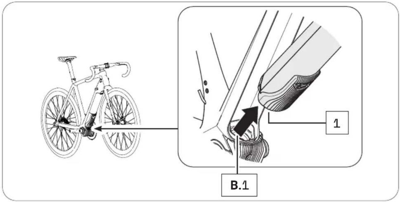
15.1 Inserting the drivepack into the e-bike
- Place the drivepack onto the corresponding interface on the bottom bracket.
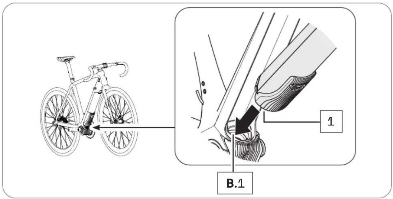
text_image
B.1 1- Swing the upper end of the drivepack into the downtube of the e-bike. When you have inserted the drivepack correctly and completely into the downtube, the locking mechanism built into the downtube automatically engages in the motor mount and locks the drivepack in the correct position (audible click).
The push button or locking lever also moves automatically into the closed position.
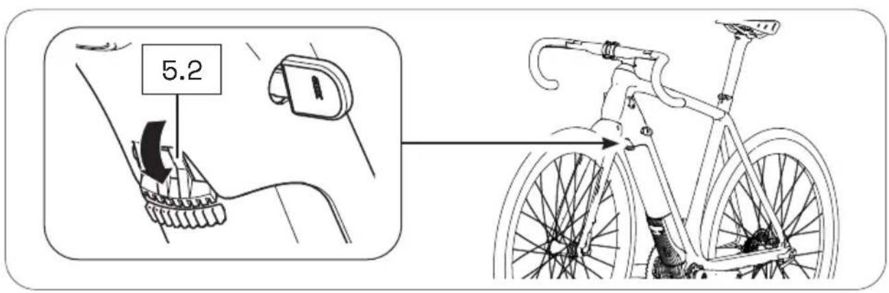
text_image
5.2- Check the drivepack is securely in position.
If the drivepack does not lock, pull it out again if necessary and then try to insert it again. Do not use the drive system if the drivepack cannot be locked to the e-bike.
15.2 Removing the drivepack from the e-bike
CAUTION
Risk of burns!
The radiator in the drivepack can become very hot during operation, meaning you may burn yourself on it.
▶ Allow the drivepack to cool down completely before touching it.

If you press the drivepack firmly against the frame before pressing the push button or releasing the locking lever, it will be easier to release the drivepack from the locking device on the frame when removing it.
-
Secure the drivepack with one hand.
-
Press the push button down with the other hand to release the drive-pack from the lock.
or
Move the locking lever upwards as far as possible to release the drive-pack from the lock.
text_image
5.2 5.1- Press and hold down the push button and carefully lower the drivepack out of its holder in the down tube.
The locking lever automatically remains in the open position.
- Remove the drivepack from the front of the interface on the bottom bracket.
text_image
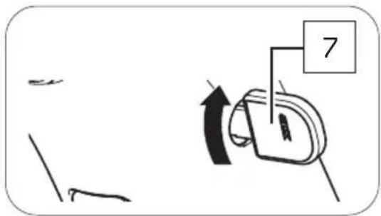
B.1 11 5.3 Securing/locking the drivepack on the e-bike
Depending on the bicycle manufacturer, a cylinder lock is integrated into the frame of your e-bike, which you can use to lock the drivepack mounted on the e-bike and thus secure it against theft etc.
-
If necessary, make sure that the drivepack is correctly attached to the e-bike.
-
Insert the key into the cylinder lock, if necessary.
-
Turn the key 90° anti-clockwise to lock the drivepack to the e-bike.
-
Remove the key from the cylinder lock.
text_image
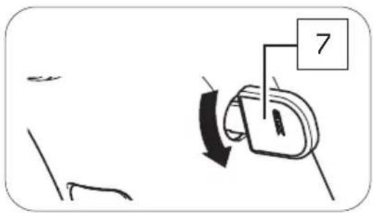
7If you want to unlock the drivepack again:
-
Insert the key into the cylinder lock.
-
Turn the key 90° clockwise to unlock the drivepack on the e-bike.
text_image
7BOTTOM BRACKET
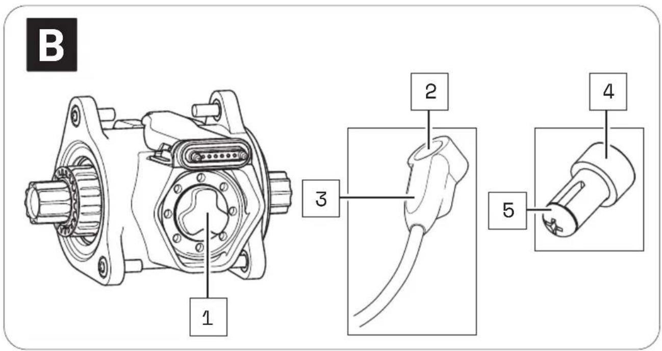
16 DETAILED VIEW & PART DESIGNATIONS: BOTTOM BRACKET
text_image
B 1 2 3 4 5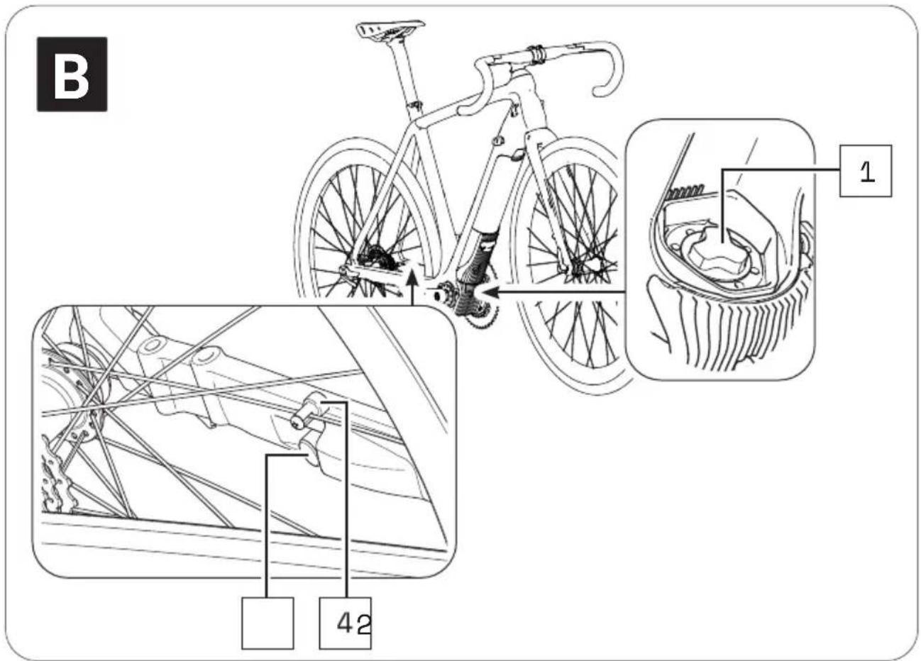
text_image
B 1 42Part designations
1 → Interface (drivepack)
2 → Speed sensor
3 → Marking (alignment of spoke magnet/speed sensor)
4 → Spoke magnet
5 → Fixing screw (spoke magnet)

The numbering 1-5 within this section refers to the individual parts of the component B (bottom bracket).
17 TECHNICAL DATA
| TECHNICAL DATA ON THE BOTTOM BRACKET | |
| Support torque, max. | → 55 Nm |
| Q-factor, min. | → 135 mm (without crank arm) |
| Chain line | → 49 mm, 52 mm |
| Protection type | → IP54 |
| Weight, approx. | → 1.3 kg |
| Operating temperature | → -5 °C to +40 °C (ambient temperature) |
| Storage temperature (< 1 month) | → -15 °C to +60 °C |
| Storage temperature (> 1 month) | → -15 °C to +25 °C |
18 USING THE BOTTOM BRACKET
The bottom bracket is already fitted to your e-bike on delivery. You are not permitted to make any changes to the bottom bracket as you may affect the safety and function of the drive system.
It may be necessary to align only the speed sensor connected to the bottom bracket as well as the corresponding spoke magnet in some circumstances.
18.1 Correct position/alignment
For the drive system to function correctly, the speed sensor and the spoke magnet must be correctly positioned and aligned on the rear wheel.
- The spoke magnet must be positioned on the spoke so that it can move past the speed sensor freely at the height of the marking. If the spoke magnet and speed sensor are too close together and there is a risk of them coming into contact, the two parts could be damaged and may need to be replaced.
- The distance between the mark on the speed sensor and the spoke magnet must be in the range between 4 – 15 mm.

If the distance between the speed sensor and spoke magnet is outside the specified range, or the speed sensor is not correctly connected, the drive function will work in "Soft Fault" mode.
→ More detailed information can be found in chapter 22.1 "Status display" or in chapter 26.1 "Status display".
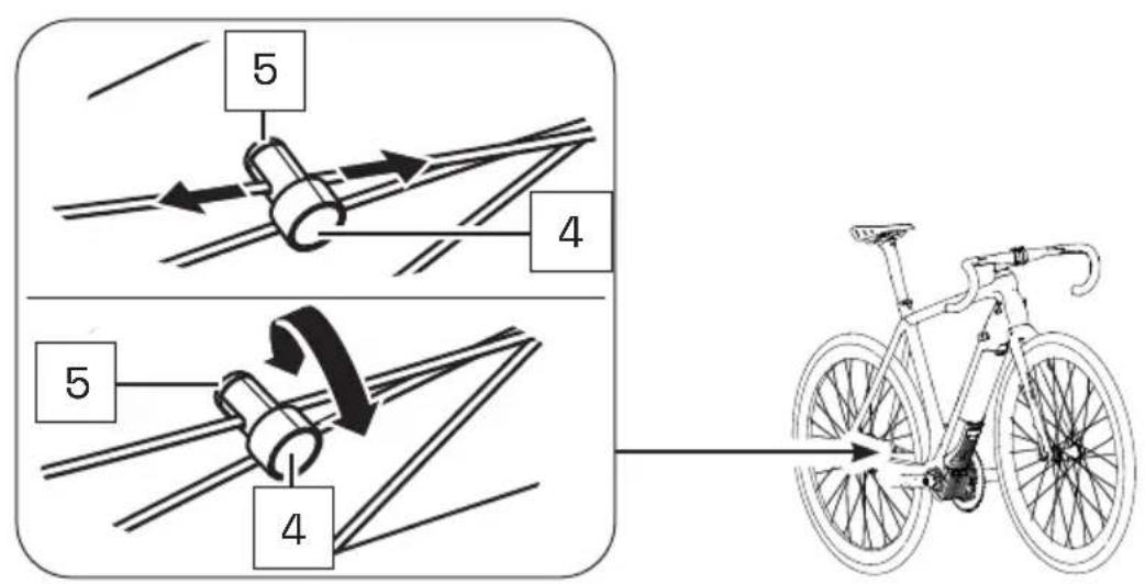
18.2 Correcting incorrect position/alignment
If you notice that the drive system is in "Soft Fault" mode because the speed sensor and spoke magnet are not correctly aligned, proceed as follows:
-
Using a screwdriver, carefully loosen the fixing screw on the spoke magnet.
-
To set the correct distance between the mark on the speed sensor and the spoke magnet:
-
Move the spoke magnet vertically on its spoke (up/down) if necessary.
- Turn the spoke magnet around its own axis if necessary.
text_image
5 4 5 4- If the problem cannot be solved, do not use the e-bike and contact an authorised specialist to have the fault rectified.
REMOTE
19 MODEL VARIANTS OF THE REMOTE
Depending on the model, you operate your drive system using Remote b, Remote fX or using Remote bX.
As the model variants differ both visually and in their handling, the models are described separately within this section in chapters 20 – 23 (Remote b) or 24 – 27 (Remote fX and Remote bX).
▶ Observe chapters 20 – 23 within this section if your e-bike is equipped with Remote b.
or
▶ Observe chapters 24–27 within this section if your e-bike is equipped with Remote fX or Remote bX.
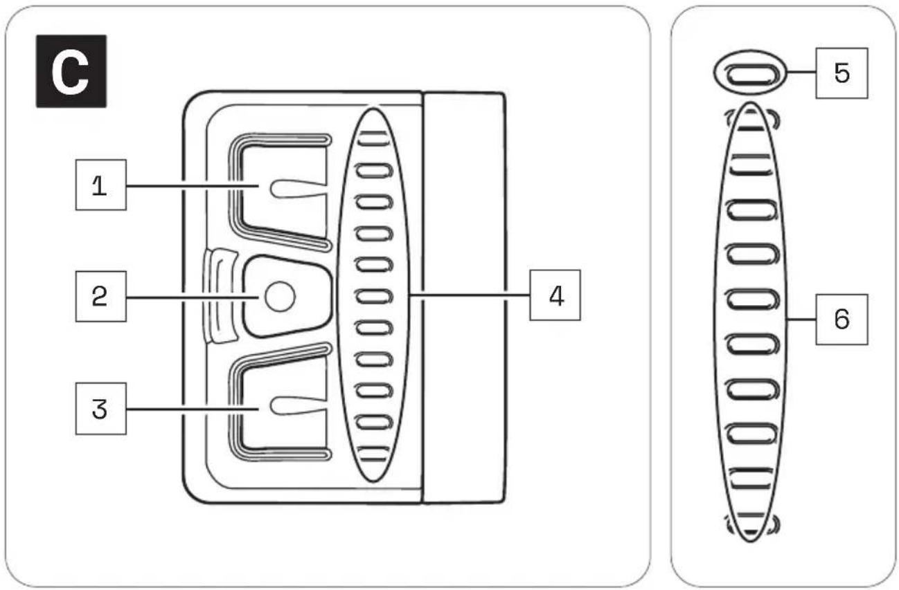
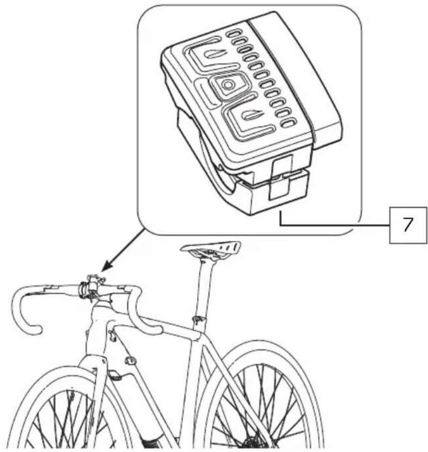
20 DETAILED VIEW & PART DESIGNATIONS: REMOTE b
text_image
C 1 2 3 4 5 6
text_image
Diagram showing a bicycle front panel with labeled components and a numbered annotation '7' pointing to it.Part designations
1 → Top button
2 → Centre button
3 → Bottom button
4 → LED display
5 → Status display
6 → Display of charging level/support level
7 → Remote fixing screw

The numbering 1-7 within this section refers to the individual parts of the component C (Remote b).
Individual parts of other components illustrated within this section are additionally marked with the corresponding component letter.
21 TECHNICAL DATA ON REMOTE b
| TECHNICAL DATA ON THE REMOTE | |
| Protection type | → IP54 |
| Weight, approx. | → 0.085 kg |
| Operating temperature | → -5 °C to +40 °C (ambient temperature) |
| Storage temperature (< 1 month) | → -15 °C to +60 °C |
| Storage temperature (> 1 month) | → -15 °C to +25 °C |
22 DISPLAYS ON THE REMOTE b
The LED displays on Remote b consists of 11 LEDs.
- The top LED serves as a status indicator informing you of the status of your e-bike.
- The remaining 10 LEDs serve as an indicator for the charge level and the pedal support level set.
22.1 Status display
The status display indicates a status change or an existing fault. The status display is not lit if no fault is detected. The LEDs light up in different colours depending on which status is displayed.
The status display:
- Flashing green = "Ready for operation"
Following successful installation of the drivepack into the e-bike, the status display flashes green briefly, indicating that you can now switch on the drive system using Remote b.
- Lit green continuously = "Bluetooth® device paired"
If you have paired a mobile device (e.g. your smartphone) via Bluetooth® function to Remote b, the status display is linked green continuously for the duration of the Bluetooth® connection between the two devices.
- Lit yellow = "Soft Fault"
If a "Soft Fault" occurs, the status display is lit yellow. In this way, the drive system indicates that there is a temporary or non-critical fault that in most cases will result in reduced performance.
If a "Soft Fault" occurs, you will be able to continue riding your e-bike, but Fazua strongly recommends not doing so to avoid further faults or damage to the drive system or to the e-bike.
- Lit red = "Hard Fault"
If a "Hard Fault" occurs, the status display is lit red. If a "Hard Fault" occurs on your e-bike, the e-bike can no longer be used and requires maintenance.
22.2 Display of charge level/support level
The charge level/support level display shows two parameters.
• The display for the charge level of the battery:
The charge level of the battery can be read off via the number of lit LEDs. Each of the 10 LEDs here represents 10 % of the total charging capacity. When the battery is fully charged, all 10 LEDs light up. If the battery is flat, no LEDs light up.
• The selected pedal support level:
Each support level is assigned a colour, i.e. You can read off the support level currently set via the colour of the lit LEDs on the display.
→ More detailed information can be found in chapter 23.3 "Support levels".
23 USING REMOTE b
WARNING
Danger due to distraction during operation!
If you are distracted when using Remote b while riding, this can result in accidents and serious injuries.
▶ Keep away from road traffic and familiarise yourself with the functions and usage of your Remote b before using your e-bike for the first time.
▶ Do not use Remote b whilst riding if you are distracted by it.
23.1 Switching the drive system on and off
▶ Switch on the drive system using Remote b by pressing one of the three buttons.
▶ Switch off the drive system using Remote b by holding down the centre button for 2 seconds.
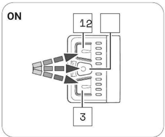
flowchart
graph TD
    A["ON"] --> B["12"]
    A --> C["3"]
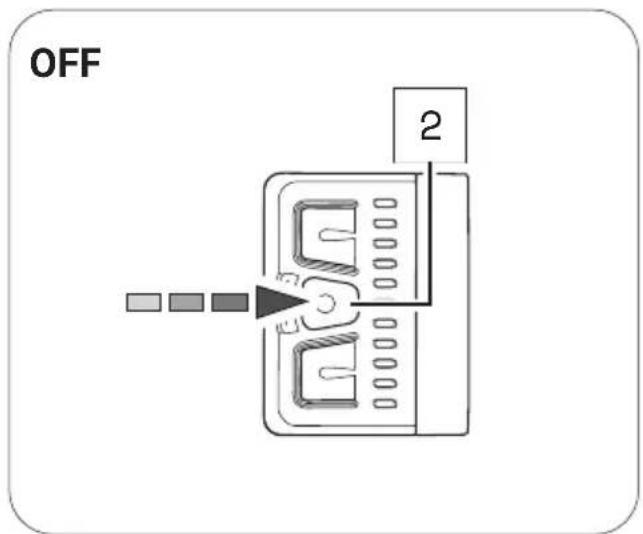
text_image
OFF 223.2 Setting the pedal support
Remote b can be used at any time to set the desired support level, including when riding.
▶ Press the top button on Remote b to switch to the next higher support level.
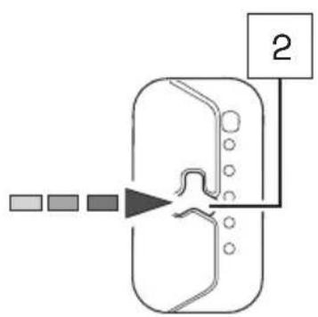
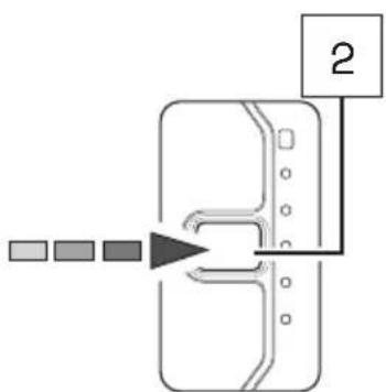
▶ Press the lower button on Remote b to switch to the next lower support level.
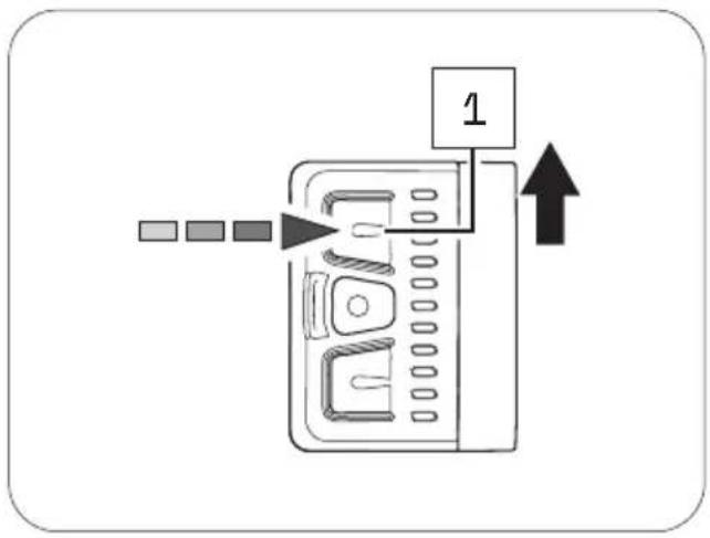
text_image
Diagram showing a device with labeled component '1' and directional arrow, likely illustrating a process or operation.
text_image
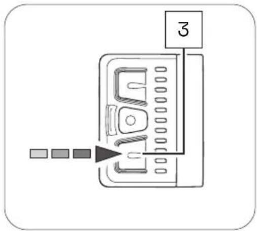
Diagram showing a device with labeled component '3' and directional arrow, likely illustrating a process or control mechanism.23.3 Support levels
No support
• The display LEDs on Remote b are lit in white.
- You are riding without electric pedal support (like a conventional bicycle).
"Breeze" support level
• The display LEDs on Remote b are lit in green.
- You are riding with minimal but active pedal support for maximum range.
"River" support level
• The display LEDs on Remote b are lit in blue.
- You are riding with reliable support for most applications.
"Rocket" support level
• The display LEDs on Remote b are lit in pink.
- You are riding with maximum support for challenging rides.

The maximum motor output for all modes can be individually configured by the manufacturer of your e-bike.
▶ Also observe the manufacturer's instructions for your e-bike to determine the maximum motor output level for your e-bike.
| "SUPPORT LEVELS" OVERVIEW TABLE | ||
| Support level Colour max. motor power: | ||
| none white 0 | W | |
| Breeze green 400 W* | ||
| River blue 400 W* | ||
| Rocket pink 400 W* | ||
* The values given here are the "theoretical" maximum motor power.
23.4 "Pushing support" mode
WARNING
Danger due to accidental start-up!
If the drive system is put into operation in inappropriate situations, this can result in accidents and serious injuries.
▶ Only use the "Pushing support" function when pushing the e-bike.
▶ Hold the e-bike securely with both hands when pushing support is active, and ensure that the wheels are in contact with the ground.
CAUTION
Risk of injury!
If you are pushing the e-bike with pushing support activated, the pedals will also turn slowly and you could be injured on them.
▶ Make sure you do not injure yourself on the rotating pedals when using the "Pushing support" function.
23.4.1 General information on the mode
Pushing support makes it easier to push the e-bike.
In "Pushing support" mode, your e-bike can reach a speed of up to 6 km/h depending on the gear set.
You can brake the speed of the e-bike to your walking pace by holding or restraining the e-bike while pushing.
Pushing support is automatically deactivated in the following situations:
• You release the bottom button,
• The wheels on the e-bike are blocked,
• The e-bike reaches a speed of more than 6 km/h.
23.4.2 Switching the "Pushing support" mode on and off
-
Use remote b to switch on support mode "none".
-
Hold down the bottom button on remote b to activate pushing support. After 2 seconds, the pushing support is activated and sets the e-bike in motion as long as you keep the button pressed.
-
Guide the e-bike with both hands and brake as necessary to adjust the speed of the e-bike with your own walking pace by holding or restraining the e-bike while pushing.
-
Switch off the pushing support by releasing the bottom button.
text_image
324 DETAILED VIEW & PART DESIGNATIONS: REMOTE fX AND REMOTE bX

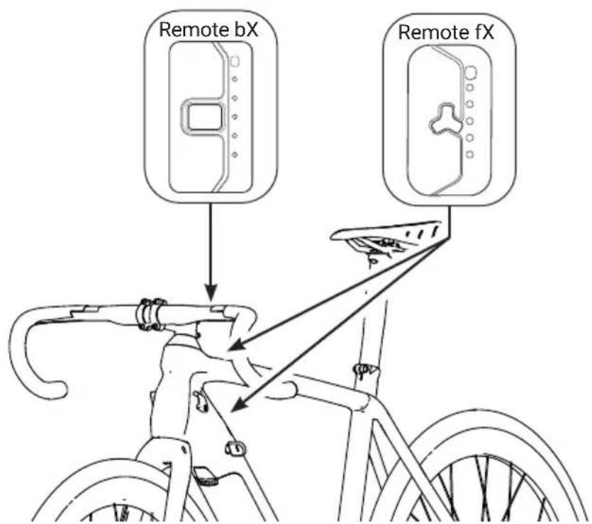
Remote fX and Remote bX are different in terms of where they are attached:
→ Remote fX is located on the frame (top or bottom tube),
→ Remote bX is located on the handlebars.

text_image
Remote bX Remote fX
Remote fX

flowchart
graph TD
    A["1"] --> B["2"]
    B --> C["3"]
    D["5"] --> E["4"]
    E --> F["Cell wall"]
Remote bX
text_image
1 2 3 4 5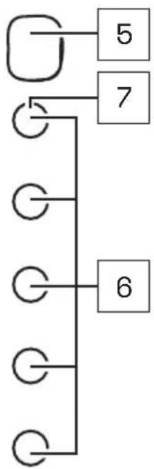
flowchart
graph TD
    A[" "] --> B["5"]
    A --> C["7"]
    C --> D["6"]
    D --> E[" "]
    E --> F[" "]
    F --> G[" "]
    G --> H[" "]
    H --> I[" "]
    I --> J[" "]
    J --> K[" "]
    K --> L[" "]
    L --> M[" "]
    M --> N[" "]
    N --> O[" "]
    O --> P[" "]
    P --> Q[" "]
    Q --> R[" "]
    R --> S[" "]
    S --> T[" "]
    T --> U[" "]
    U --> V[" "]
    V --> W[" "]
    W --> X[" "]
    X --> Y[" "]
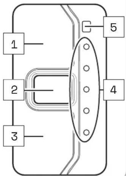
Part designations
1 → Top contact sensor
2 → Centre button
3 → Bottom contact sensor
4 → LED display
5 → Brightness sensor
6 → Display of charging level/support level
7 → Status display

The numbering 1-7 within this section refers to the individual parts of the component C (Remote fX and Remote bX).
Individual parts of other components illustrated within this section are additionally marked with the corresponding component letter.
25 TECHNICAL DATA FOR REMOTE fX AND REMOTE bX
| TECHNICAL DATA ON THE REMOTE | |
| Protection type(in installed condition) | → IP54 |
| Weight, approx. | → 0.048 kg |
| Operating temperature | → -5 °C to +40 °C (ambient temperature) |
| Storage temperature (< 1 month) | → -15 °C to +60 °C |
| Storage temperature (> 1 month) | → -15 °C to +25 °C |
26 DISPLAYS ON REMOTE fX AND REMOTE bX
The LED display on the remote consists of 5 LEDs.
- All five LEDs together serve as a display for the charge level and the pedal support level set.
- The upper of the five LEDs also serves as a status indicator, informing you about the status of your e-bike.
2 6.1 Status display
The status display indicates a status change or an existing fault. If no fault is detected, the status display LED functions as one of the five LEDs to display the charge level or the support level set.
The status display LEDs light up in different colours depending on which status is displayed.
The status display:
- Flashing green = "Ready for operation"
Following successful installation of the drivepack into the e-bike, the status display flashes green briefly, indicating that you can now switch on the drive system using Remote fX/Remote bX.
- Flashing yellow = "Soft Fault"
If a "Soft Fault" occurs, the status display flashes yellow. In this way, the drive system indicates that there is a temporary or non-critical fault that in most cases will result in reduced performance.
If a "Soft Fault" occurs, you will be able to continue riding your e-bike, but Fazua strongly recommends not doing so to avoid further faults or damage to the drive system or to the e-bike.
- Flashing red = "Hard Fault"
When a "Hard Fault" occurs, the status display flashes red. If a "Hard Fault" occurs on your e-bike, the e-bike can no longer be used and requires maintenance.
2 6.2 Display of charge level/support level
The charge level/support level display shows two parameters.
• The display for the charge level of the battery:
The charge level of the battery can be read off via the number of lit LEDs. Each of the 5 LEDs here represents 20 % of the total charging capacity. When the battery is fully charged, all 5 LEDs light up.
If the battery is flat, the upper LED of the status indicator lights up white or no LED lights up.
• The selected pedal support level:
Each support level is assigned a colour, i.e. You can read off the support level currently set via the colour of the lit LEDs on the display.
→ More detailed information can be found in chapter 27.3 "Support levels".
27 USING THE REMOTE fX AND REMOTE bX
WARNING
Danger due to distraction during operation!
If you are distracted when using Remote fX/Remote bX while riding, this can result in accidents and serious injuries.
▶ Keep away from road traffic and familiarise yourself with the functions and usage of your Remote fX/Remote bX before using your e-bike for the first time.
▶ Do not use Remote fX/Remote bX whilst riding if you are distracted by it.
2 7. 1 Switching the drive system on and off
▶ Switch on the drive system using Remote fX/Remote bX by pressing the centre button.
▶ Switch off the drive system using Remote fX/Remote bX by holding down the centre button for 1 second.
flowchart
graph TD
    A["Start"] --> B{Decision}
    B -->|Yes| C["Step 1"]
    B -->|No| D["Step 2"]
Remote fX
flowchart
graph TD
    A["Input 1"] --> B["Process Step"]
    B --> C["Output 2"]
Remote bX
2 7. 2 Setting the pedal support level
Remote fX/Remote bX can be used at any time to set the desired support level, including when riding.
Tap the top contact sensor on Remote fX/Remote bX to change to the next higher support level.
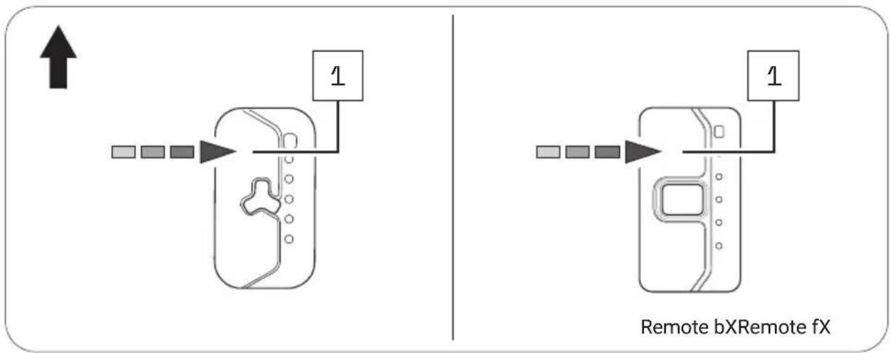
flowchart
graph TD
    A["Start"] --> B["Device with Path 1"]
    B --> C["Remote bX Remote fX"]
    C --> D["End"]
Tap the bottom contact sensor on Remote fX/Remote bX to change to the next lower support level.
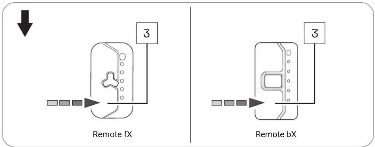
flowchart
graph TD
    A["Start"] --> B["Remote fX"]
    B --> C["3"]
    D["Start"] --> E["Remote bX"]
    E --> F["3"]

If you are riding in rain mode, set the desired support level using the centre button.
→ More detailed information can be found in chapter 27.5 "Rain mode".
27.3 Support levels
No support (white)
- The display LEDs on Remote fX/Remote bX are lit in white.
- You are riding without electric pedal support (like a conventional bicycle).
"Breeze" support level
- The display LEDs on Remote fX/Remote bX are lit in green.
- You are riding with minimal but active pedal support for maximum range.
"River" support level
- The display LEDs on Remote fX/Remote bX are lit in blue.
- You are riding with reliable support for most applications.
"Rocket" support level
- The display LEDs on Remote fX/Remote bX are lit in pink.
- You are riding with maximum support for challenging rides.

The maximum motor output for all modes can be individually configured by the manufacturer of your e-bike.
▶ Also observe the manufacturer's instructions for your e-bike to determine the maximum motor output level for your e-bike.
| "SUPPORT LEVELS" OVERVIEW TABLE | ||
| Support level Colour max. motor power: | ||
| none white 0 | W | |
| Breeze green 400 W* | ||
| River | blue | 400 W* |
| Rocket | pink | 400 W* |
* The values given here are the "theoretical" maximum motor power.
2 7. 4 Re-starting the drive system
▶ Hold down the centre button for 8 seconds to power down your drive system completely: Clear all LEDs.
If the drive system is ready for switching back on, the status display will flash green: You can then start your drive system again as normal.
2 7. 5 Rain mode
Rain mode prevents rain drops from accidentally adjusting the support level of your e-bike.
If you have activated the rain mode, use the centre button to set the desired support level:
- Activate rain mode by holding down the centre button for 2 seconds.
A short blue LED animation appears.
- In rain mode, press the centre button once briefly to switch to the next higher support level.
By briefly pressing the centre button again, you can switch to the next higher support level in the following order:
No support → "Breeze" → "River" → "Rocket" → No support etc.
- To return from the rain mode to the regular operating mode, hold down the centre button again for 2 seconds.
2 7. 6 Switching the bicycle lighting on and off

Depending on the model, your e-bike has a bicycle light that you can switch on and off using the Remote fX/Remote bX.
IMPORTANT: The bicycle lighting can only be switched on and off in regular operating mode using the Remote fX/Remote bX, not in rain mode!
- If necessary, deactivate rain mode by holding down the centre button for about 2 seconds.
- Press the centre button once briefly to turn on the bicycle lights.
- Press the centre button again once briefly to turn off the bicycle lights.
27.7 Bluetooth® connection
You can connect your mobile phone to your drive system via the Fazua Rider app. If the connection has been established successfully, the LEDs on the Remote fX/Remote bX flash blue three times.
BATTERY
28 MODEL VARIANTS OF THE BATTERY
Depending on the model, your drive system is powered by the Battery 250 or Battery 250 X.
Since the two model variants differ in appearance, you may find different model-dependent illustrations next to each other in this section.
Different handling of the model variants after automatic switch-off of the battery:
The Battery 250 switches off automatically if the e-bike has not moved for 8 hours and no button or touch sensor has been pressed on the remote.
The Battery 250 X switches off automatically if the e-bike has not moved for 1 hour and no button or touch sensor has been pressed on the remote.
▶ Press the on/off button once on the battery to switch the Battery 250 or Battery 250 X on again ("wake up").

Both model variants have the function for displaying the "state of health" (SOH) of the battery by double-clicking on the on/off button on the battery.
The SOH is displayed in 20% increments (similar to the battery charge indicator): If all five LED's are flashing, the battery has a SOH of 100%, if four LED's are flashing 80%, etc.
29 DETAILED VIEW & PART DESIGNATIONS: BATTERY
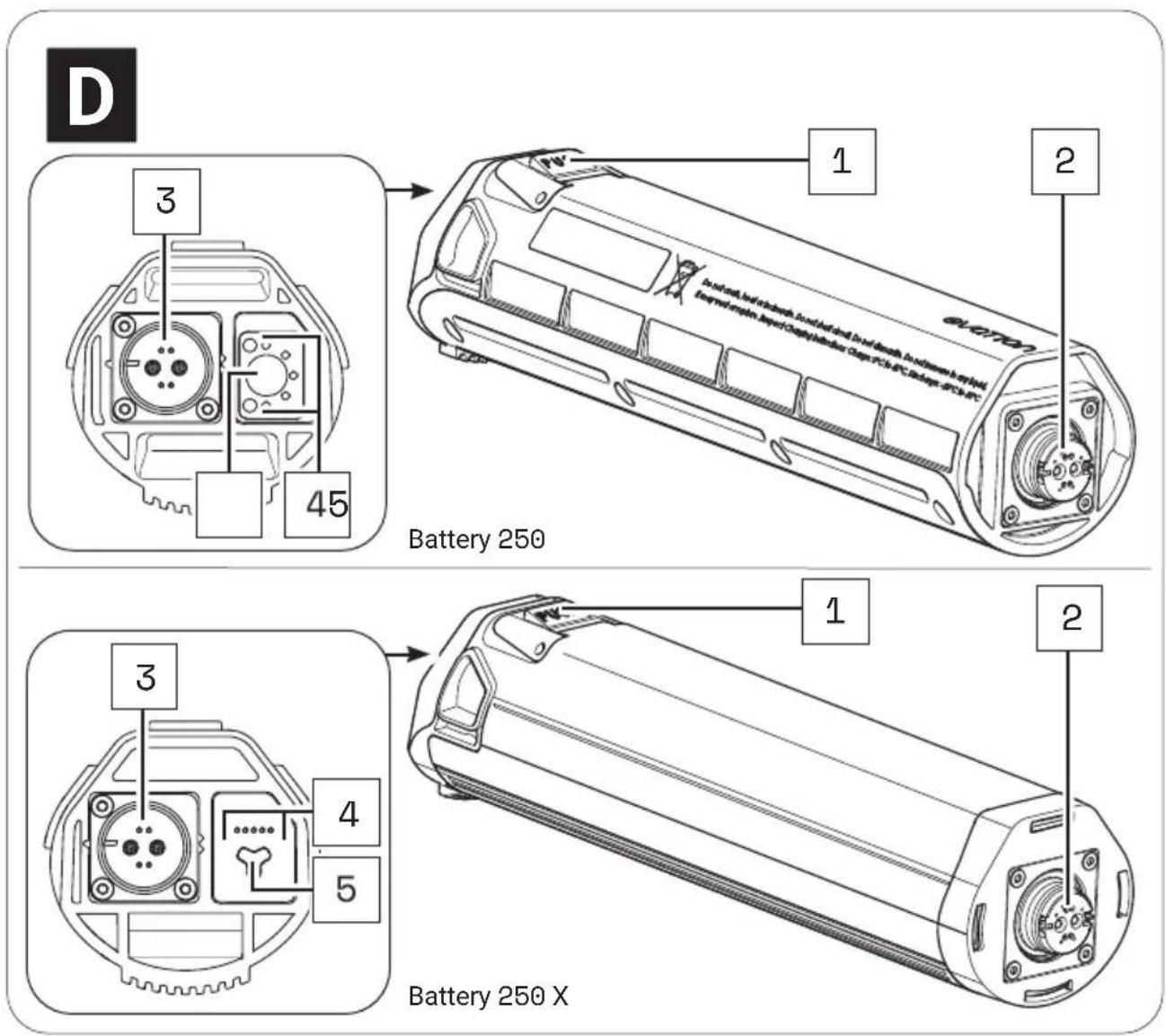
text_image
D 3 45 Battery 250 1 2 E-CT70 E-CT70 E-CT70 E-CT70 E-CT70 Battery 250 X 1 2 3 4 5Part designations
1 → Pushbutton (battery lock)
2 → Interface (Drivepack)
3 → Charging socket
4 → Charge level indicator*
5 → On/off button
* The charge level indicator of the Battery 250 X is only visible when the corresponding LEDs are lit, but not, for example, when the battery is switched off.

The numbering 1–5 within this section refers to the individual parts of the component D (battery).
Individual parts of other components illustrated within this section are additionally marked with the corresponding component letter.
30 TECHNICAL DATA
| TECHNICAL DATA ON THE BATTERY | |
| Nominal voltage | → 36 V |
| Nominal capacity | → 7 Ah |
| Output | → 252 Wh |
| Protection type | → IP54 |
| Weight, approx. | → 1.4 kg |
| Operating temperature | → -5 °C to +40 °C (ambient temperature) |
| Storage temperature (< 1 month)* | → -15 °C to +60 °C |
| Storage temperature (> 1 month)* | → -15 °C to +25 °C |
* Please also note the information on the storage time-dependent temperature ranges for the battery in chapter "Storage and transport".
31 USING THE BATTERY
31.1 Checking and switching on battery

WARNING
Risk of explosion and fire!
A damaged or dirty battery may explode and/or cause a fire.
▶ Never insert a damaged battery into the drivepack.
▶ Check the battery for visible damage, such as cracks or burn marks, before each insertion.
▶ Make sure that the interfaces on the battery are free of dirt before using it.

You can query the charge level of the battery at any time, by pressing the on/off button once: The number of illuminated LEDs indicate the charge level. Thus each illuminated LED corresponds to 20% of the total charging capacity. When the battery is fully charged, all 5 LEDs light up.
-
Check the battery for visible damage (visual check).
-
Press the on/off button on the battery once to turn on the battery:
The LEDs of the charge level indicator next to the on/off button light up and indicate the current charge level of the battery.
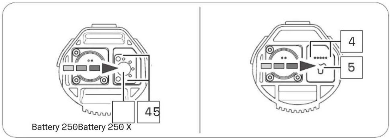
text_image
Battery 250Battery 250 X 45 4 5If none of the LEDs on the charge indicator light up after pressing the on/off button, this indicates that the battery is damaged.
In this case, do not insert the battery into the drivepack, but contact an authorised specialist.
31.2 Inserting the battery into the drivepack
-
Hold the drivepack with one hand and the battery with the other.
-
Position the battery with the interface forwards in front of the empty battery receptacle and align it so that the battery lock push button is on the same side as the corresponding opening on the drivepack.
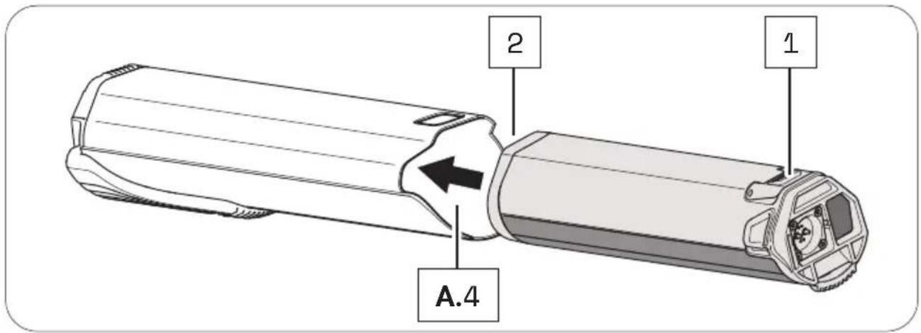
text_image
A.4 2 1The battery is designed so that it can only be inserted into the battery receptacle when correctly aligned. So, if you have problems inserting the battery into the battery holder, it may be because you have not aligned the battery correctly.
Therefore, in this case, first check the correct alignment of the battery and try inserting it again.
If the battery cannot be inserted into the battery receptacle despite correct alignment, this may indicate that one of the components is damaged.
Do not use the drive system if the battery cannot be inserted into the battery holder, but contact an authorised specialist.
- Carefully insert the battery as far as possible into the battery holder of the drivepack until you hear a click.
When you have inserted the battery correctly and completely into the battery holder, the push button on the battery slides into the corresponding opening on the drivepack and locks the battery in place.
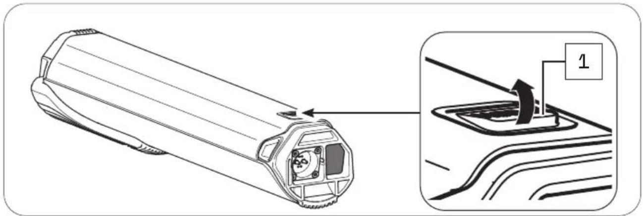
text_image
Technical diagram showing a cylindrical device with internal components and an inset view of the component labeled '1'If the battery does not lock, pull it out again if necessary, make sure that there is no dirt inside the drivepack to obstruct insertion, and then try inserting the battery again. Do not use the drive system if the battery cannot be locked. In this case, contact an authorised specialist to have the fault rectified.
31.3 Removing the battery from the drivepack
CAUTION
Pinch risk!
You can pinch your fingers when removing the battery from the drivepack.
When pressing the push button or removing the battery, be careful not to pinch your fingers.
- Hold the drivepack with one hand and secure the battery with the other.
- Press the push button as far as it will go to release the battery from the lock.
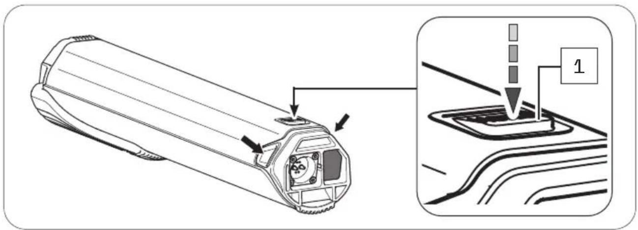
text_image
Technical diagram showing a mechanical component with labeled parts and an inset view of a control panel with step 1.- Press and hold the push button, grasp the battery on the two handles and gently pull the battery out of the battery holder.
The two handles are located at the side of the upper battery end (see arrows).
31.4 Switching off the battery
▶ Turn off the battery by pressing and holding the on/off button.
31.5 Charging the battery
WARNING
Fire hazard due to incorrect handling!
If you handle the battery improperly or try to charge it with an incompatible charger, you could cause a fire.
▶ To charge the battery, use only original and compatible evation chargers from Fazua.
The charger and battery heat up during charging, so keep away from combustible materials.
▶ Do not leave the battery and charger unattended during charging.
WARNING
Risk of electric shock!
Improper handling of the charger or incorrect mains connection may expose you and others to the risk of electric shock.
▶ Observe the instructions in section "Charging process".
You can either leave the battery in the drivepack during charging or remove it from the drivepack and charge it separately. The charging process can also be interrupted at any time.
You cannot charge the battery if the temperature is outside the permissible charging temperature. This is not possible even if the battery is connected to the charger.
Charging is only possible again when the permissible charging temperature has been reached.
▶ Fully charge the battery prior to initial operation so that you can use the full capacity of the battery.
31.5.1 Connect battery to the charger
- Insert the charging plug into the charging socket on the battery. Since the charging plug is magnetically coded, it can only be plugged in in the intended position.
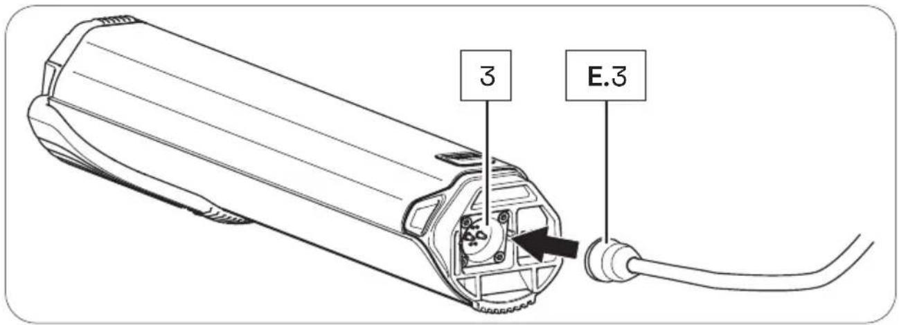
text_image
3 E.3- Plug the power plug into a suitable wall outlet to establish the power connection.
The charging process starts automatically after connection to the mains.
31.5.2 Ending the charging process
- Then disconnect the charger from the power supply by removing the mains plug from the socket.
- Disconnect the charger from the battery by removing the charger plug from the charging socket on the battery.
- Replace the drivepack with the battery correctly on the e-bike.
31.6 Charging process
Charging begins as soon as you have connected the charger's charger plug to the charger socket on the battery and the charger to the power supply.
The flashing LEDs on the battery charge indicator indicate that the battery is being charged.
3 1.7 Battery charge level indicator
As soon as you have switched on the battery, the charge status display automatically shows a start-up animation. Immediately afterwards, the LEDs briefly indicate the current charge level of the battery.
Depending on the charge level, the number of LEDs varies, with each LED representing 20 % of the capacity. If all five LEDs are lit, the battery is fully charged.
As soon as the battery is fully charged, the LEDs of the charge level indicator go out.
When the battery is switched on, press the on/off button on the battery to check the charge status, e.g. before or during a (longer) trip.
CHARGER
32 MODEL VARIANTS OF THE CHARGER
Depending on the model, you charge the battery of your drive system using Charger A or Charger S (EU/US).
The two model variants differ in some respects visually and with regard to their technical data. You may therefore find different model-dependent illustrations or information in this section.
If none of the model variants is explicitly mentioned, the descriptions refer to all model elements.
33 DETAILED VIEW & PART DESIGNATIONS: CHARGER
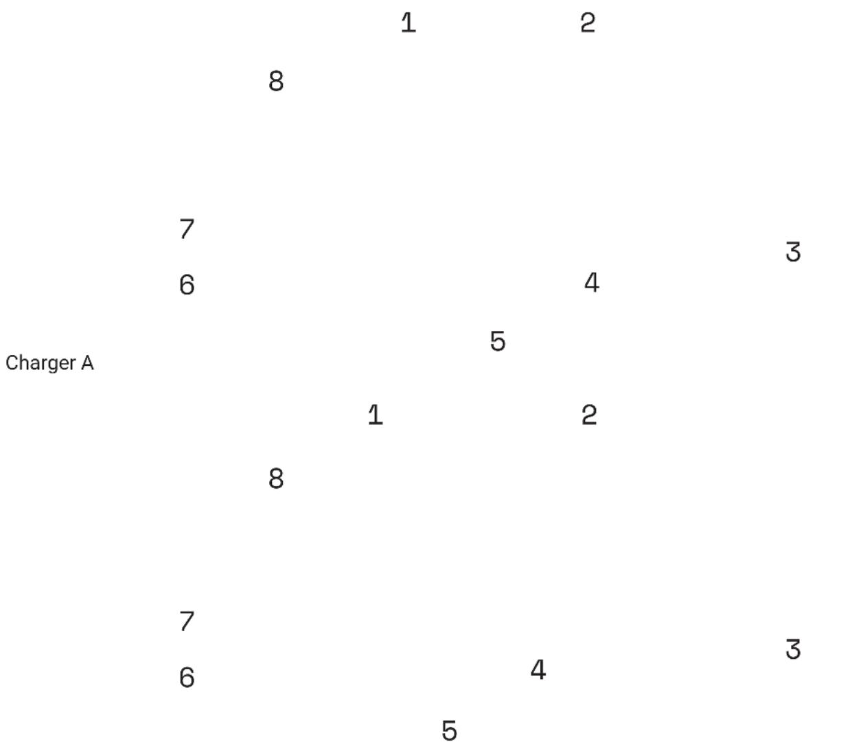
Charger S (EU/US)
| evation
EN-75
Part designations
1 → Mains adapter
2 → Charging cable
3 → Charging plug
4 → Mains cable
5 → Mains plug (power supply)*
6 → Plug
7 → Mains socket
8 → LED display
* Different from country to country, therefore not pictured.

The numbering 1–8 within this section refers to the individual parts of the components E (charger).
Individual parts of other components illustrated within this section are additionally marked with the corresponding component letter.
34 TECHNICAL DATA
| TECHNICAL DATA ON THE CHARGER | |
| Nominal input voltage | 100-240 V AC (Charger A)→ 220-240 V AC (Charger S (EU))100-110 V AC (Charger S (US)) |
| Frequency | → 50/60 Hz |
| Charging current | → 2 A |
| Charging time, approx. | → 3.5 h |
| Protection class | → 2 [Symbol: □] |
| Protection type | → IP54 |
| Weight, approx. | → 0.6 kg (Charger A)0.39 kg (Charger S (EU/US)) |
| Operating temperature | → 0 °C to +45 °C |
| Storage temperature | → 0 °C to +45 °C |
35 USING THE CHARGER
WARNING
Risk of electric shock and fire!
If you use a damaged charger you could expose yourself and others to the risk of an electric shock. If you use the charger improperly or with an incompatible battery, you could cause a fire.
Therefore check all individual part for damage before using the charger.
▶ Never use a damaged charger.
▶ Only use the charger in dry indoor areas.
▶ Keep water or any liquids away from the charger or all individual parts of the charger.
The charger and battery heat up during charging, so keep away from combustible materials and do not leave the two components unattended during charging.
▶ During charging place the charger and battery on a well ventilated surface.
▶ Only use the charger to charge the original and compatible evation battery from Fazua.
▶ Never attempt to charge non-rechargeable batteries!
35.1 Preparing the charger
- Take the mains adapter and the mains cable.
- Plug the appliance plug of the mains cable into the socket on the mains adapter.
35.2 Connector charger to the battery
WARNING
Risk of electric shock!
If the mains connection is incorrect, you and others may be exposed to the risk of electric shock.
▶ First connect the charger to the battery before you connect the charger to the power supply.
▶ Only connect the charger to an easily accessible and properly installed earth contact outlet.
▶ Make sure that the mains voltage at the mains connection corresponds to the information on the charger.
- Plug the charger plug into the charging socket on the battery.
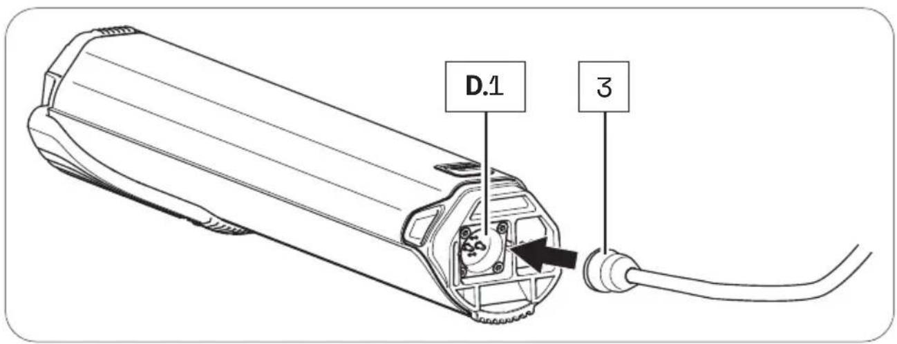
text_image
D.1 3- Plug the mains plug into a suitable wall outlet to establish the power connection.
The charging process starts automatically after connection to the mains. During the charging process, the LED indicator on the mains adapter lights up red and signals that the battery is being charged.
When the colour of the LED indicator changes to green, this signals that the battery is fully charged.
3 5.3 Unplugging the charger from the battery
WARNING
Risk of electric shock!
If the mains connection is incorrect, you and others may be exposed to the risk of electric shock.
▶ First disconnect the charger from the power supply before you disconnect the charger from the battery.
- When charging is complete, unplug the charger from the outlet to disconnect it from the mains.
- Then disconnect the charger from the battery by removing the charging plug from the socket.
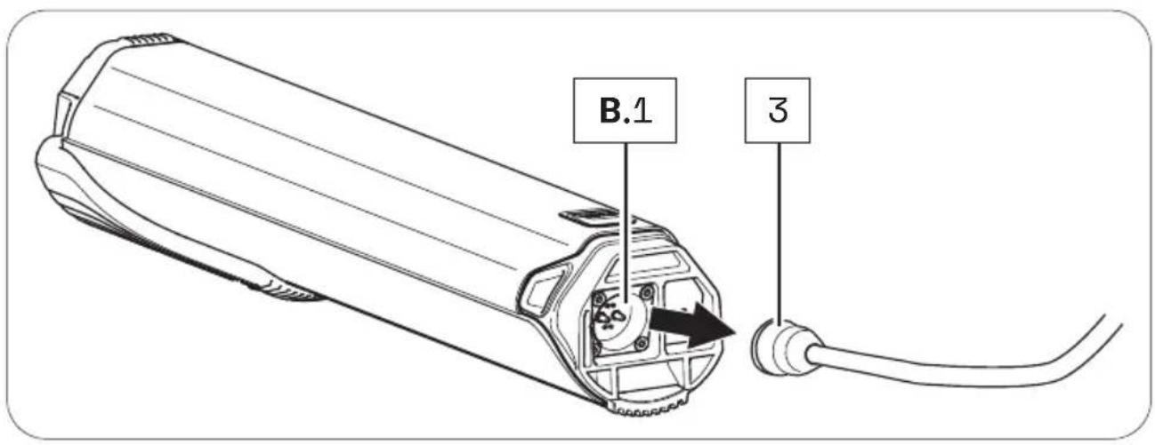
text_image
B.1 3- Then disconnect the mains cable from the mains adapter and keep the two parts of the charger separate from each other.

FAZUA
Fazua GmbH
pedelec drive system
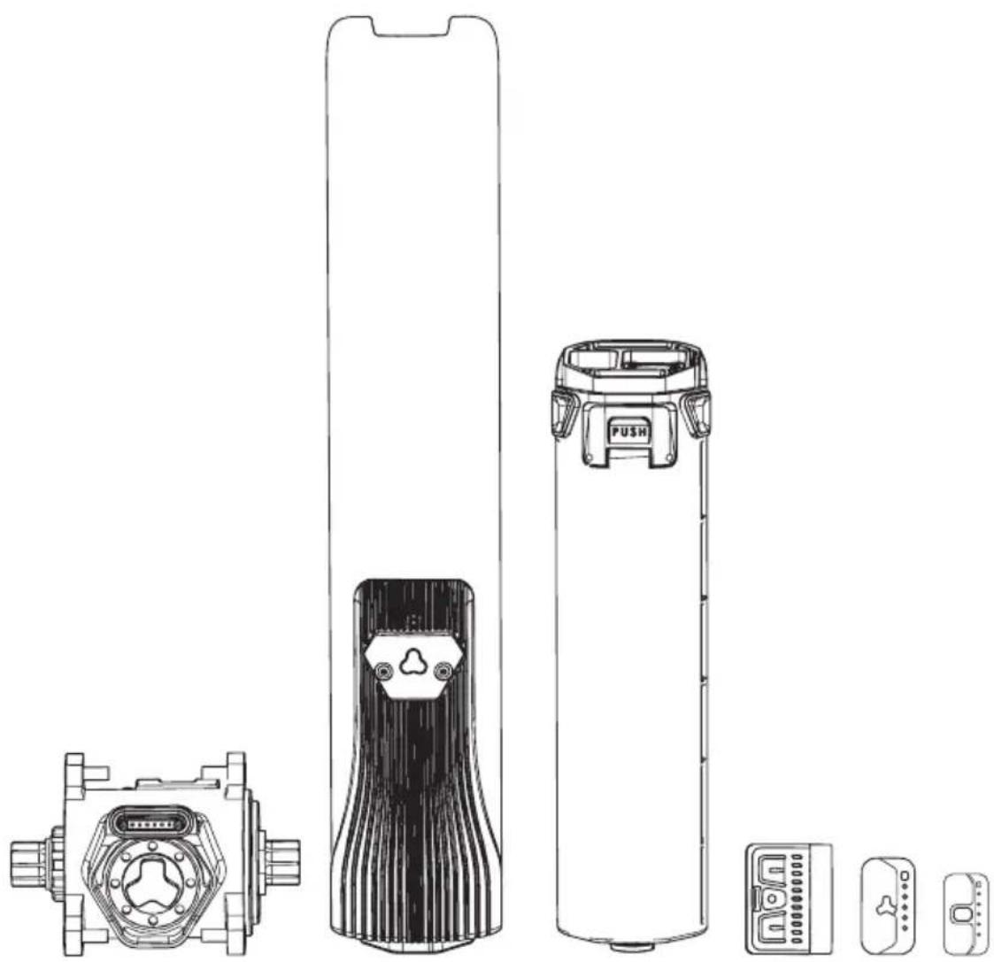
natural_image
Technical line drawings of various electronic devices including a battery, push button, and display components (no text or symbols)natural_image
Technical line drawing of a mechanical component with curved and straight sections (no text or symbols)B
natural_image
Technical line drawing of a mechanical assembly with gears and housing (no text or symbols)natural_image
Technical line drawing of a battery casing with internal compartments and mounting holes (no text or symbols)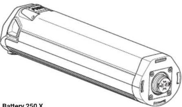
natural_image
Technical line drawing of a cylindrical battery with mounting flanges and internal components (no text or symbols)Battery 250 X
E
Charger
(Details ab Seite DE-75)
Charger A Charger S (EU/US)

natural_image
Line drawing of a charger S (EU/US) connected to a cable and terminal connector (no text or symbols on the diagram itself)
natural_image
Simple line drawing of a rectangular device connected to a terminal outlet (no text or symbols)
text_image
Diagram illustrating bicycle wheel assembly and battery pack installation, with labeled components and assembly steps.text_image
Diagram illustrating bicycle arm joint positioning with labeled parts A and B, showing structural changes and movement directions.text_image
Diagram illustrating bicycle seat positioning and movement, labeled A and B with directional arrows indicating movement.natural_image
Diagram of a device emitting beams from a fan, with a labeled component 'C' (no text or symbols on the diagram itself)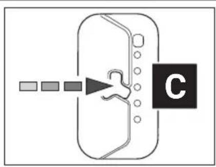
flowchart
graph TD
    A["Start"] --> B["Process Step"]
    B --> C["C"]
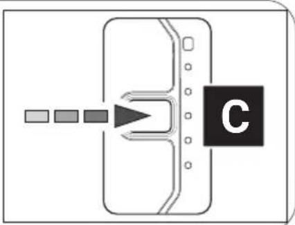
flowchart
graph TD
    A[" "] --> B[" "]
    B --> C[" "]
    C --> D["C"]
natural_image
Diagram of a device with a labeled component 'C' and directional arrows pointing to it (no text or symbols beyond the label)Fazua Rider App by CoModule:
natural_image
Technical diagram of a mechanical component with pins and a downward arrow indicating a process (no text or symbols present)text_image
Diagram showing a mechanical or electrical component with an arrow indicating direction and a label '7' pointing to it.BOTTOM BRACKET
text_image
Diagram showing a bicycle front panel with labeled components and a numbered annotation '7' pointing to it.Teilebezeichnungen
1 → Obere Taste
2 → Mitteltaste
3 → Untere Taste
4 → LED-Anzeige
5 → Statusanzeige
text_image
Diagram showing a device with labeled component '1' and an upward arrow indicating direction or flow.
text_image
3text_image
Remote bX Remote fX
Remote fX
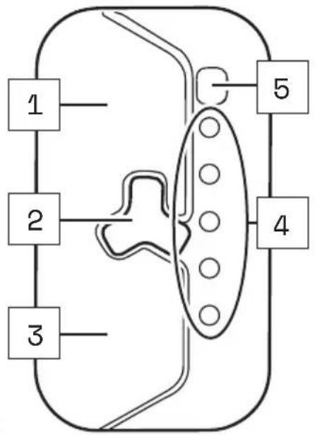
flowchart
graph TD
    A["1"] --> B["2"]
    B --> C["3"]
    C --> D["4"]
    D --> E["5"]
    E --> F["End"]
Remote bX

text_image
1 2 3 4 5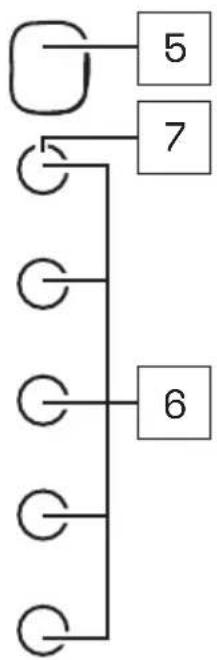
flowchart
graph TD
    A[" "] --> B["5"]
    A --> C["7"]
    C --> D["6"]
    D --> E[" "]
    E --> F[" "]
    F --> G[" "]
    G --> H[" "]
    H --> I[" "]
    I --> J[" "]
    J --> K[" "]
    K --> L[" "]
    L --> M[" "]
    M --> N[" "]
    N --> O[" "]
    O --> P[" "]
    P --> Q[" "]
    Q --> R[" "]
    R --> S[" "]
    S --> T[" "]
    T --> U[" "]
    U --> V[" "]
    V --> W[" "]
    W --> X[" "]
Teilebezeichnungen
flowchart
graph TD
    A["Input 1"] --> B["Process Step"]
    B --> C["Output 2"]
Remote bXRemote fX
text_image
Battery 250 45 Battery 250 X 4 5text_image
Technical diagram showing a cylindrical device with internal components and an inset view of the component labeled '1'text_image
Technical diagram showing a car interior with labeled components and a zoomed-in view of the component's center.text_image
E 1 2 8 7 6 4 3 5 Charger A Charger S (EU/US)Teilebezeichnungen
pedelec drive system

natural_image
Technical line drawings of various electronic devices including a pusher, battery pack, and display unit (no text or symbols present)natural_image
Technical line drawing of a mechanical component with curved and straight sections (no text or symbols)B
natural_image
Technical line drawing of a mechanical assembly with gears and housing (no text or symbols)C
Afstandsbediening
(Details vanafpag.NL-50)
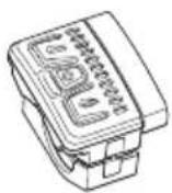
Afstandsbediening b
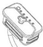
Afstandsbediening fX
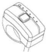
Afstandsbediening bX
natural_image
Technical line drawing of a cylindrical mechanical component with internal slots and mounting holes (no text or symbols)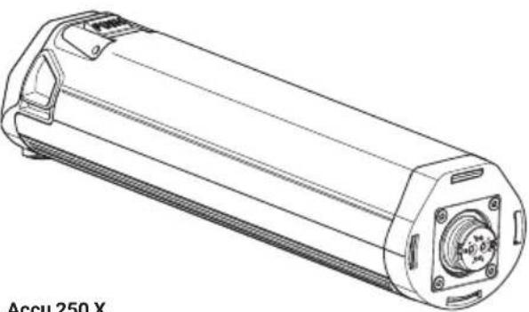
natural_image
Technical line drawing of a cylindrical mechanical component with mounting flanges and central hub (no text or symbols)E
Lader
(Details vanaf pag. NL-75)
Lader A Lader S (EU/US)
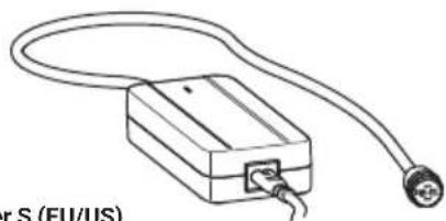
natural_image
Line drawing of a rectangular electronic device with a coiled cable and connector, labeled 'r S (EU/US)' at the bottom (no other text or symbols)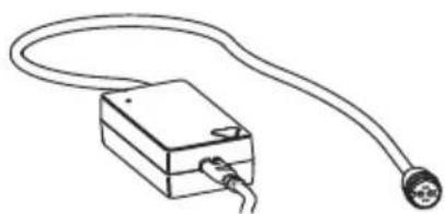
natural_image
Simple line drawing of a rectangular device connected to a terminal outlet (no text or symbols)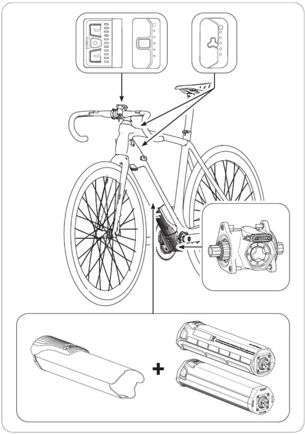
text_image
Diagram illustrating bicycle wheel assembly and battery pack installation, with labeled components and assembly stepstext_image
Diagram illustrating bicycle wheel assembly and rail handling steps, labeled A and B with directional arrows- Controleer of de motoreenheid stevig vastzit.
text_image
Diagram illustrating bicycle seat positioning and movement, labeled A and B with directional arrows indicating movement.natural_image
Diagram of a device with a labeled component 'C' and four colored square indicators pointing to its left side (no text or symbols on the device itself)6 OPTIONELE ACCESSOIRES
Onderbuisbeschermer
AANWIJZING
Fazua Rider App by CoModule:
text_image
Diagram showing a mechanical or electrical component with an arrow indicating direction and a label '7' pointing to a section.TRAPASAANDRIJVING
16 GEDETAILLEERD OVERZICHT EN COMPONENTNAMEN: TRAPASAANDRIJVING

text_image
B 1 2 3 4 5
text_image
B 42 1Componentnamen
text_image
Diagram showing a bicycle front panel with labeled components and a numbered annotation '7' pointing to it.Componentnamen
text_image
OFF/UIT 223.2 Trapondersteuning instellen
text_image
Diagram showing a device with labeled components and an upward arrow indicating direction or flow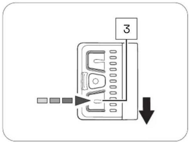
text_image
Diagram showing a device with labeled component '3' and directional arrow indicating movement or flowflowchart
graph TD
    A["1"] --> B["2"]
    B --> C["3"]
    C --> D["4"]
Afstandsbediening fX
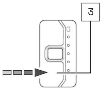
text_image
Diagram showing a device with labeled connection point '3' and color-coded indicators below itAfstandsbediening bX

text_image
Technical diagram showing a car interior with a component being inserted, labeled with number 1natural_image
Technical line drawings of various electronic devices including a battery, push button, and display components (no text or symbols)natural_image
Technical line drawing of a mechanical component with curved and straight sections (no text or symbols)B
natural_image
Technical line drawing of a mechanical assembly with gears and housing (no text or symbols)natural_image
Technical line drawing of a battery casing with internal compartments and mounting holes (no text or symbols)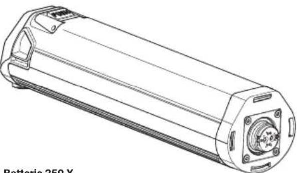
natural_image
Technical line drawing of a battery pack with mounting flanges and internal components (no text or symbols)Batterie 250 X
natural_image
Line drawing of a plug-in electrical connector with a terminal terminal (no text or symbols on the diagram itself)
natural_image
Simple line drawing of a rectangular device connected to a terminal outlet (no text or symbols)
text_image
Diagram illustrating bicycle wheel assembly and maintenance components with labeled parts and assembly steps2 À PROPOS DE CE MANUEL
text_image
Diagram illustrating bicycle wheel assembly and steering mechanism with labeled parts A and Btext_image
Diagram illustrating bicycle seat positioning and movement, labeled A and B with directional arrows indicating movement.flowchart
graph LR
    A["Device with sensor and signal arrows"] --> B["Device with connector and feedback loop"]
    B --> C["Device with connector and signal arrow"]
    C --> D["Device with connector and feedback loop"]
natural_image
Diagram of a device with color-coded indicators and a labeled section (no text or symbols)natural_image
Technical diagram of a mechanical component with pins and a downward arrow indicating a process (no text or symbols)12 DÉCLARATION DE CONFORMITÉ CE
1 → Interface (Drivepack)
text_image
Diagram showing a bicycle front panel with labeled components and a numbered annotation '7' pointing to it.flowchart
graph TD
    A["ON/MARCHE"] --> B["12"]
    A --> C["3"]
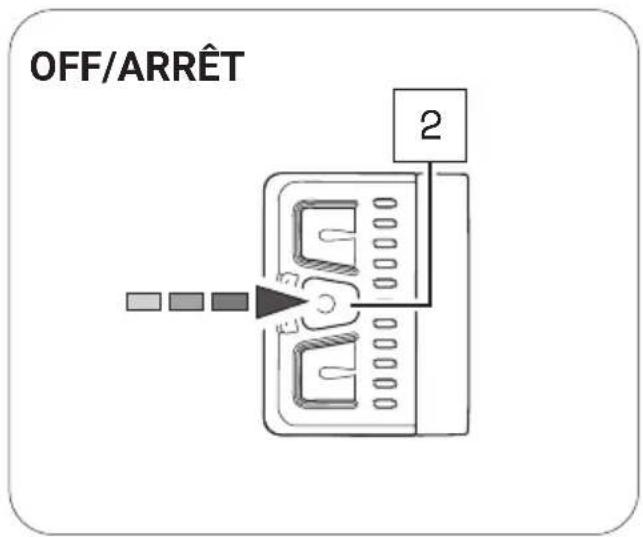
text_image
OFF/ARRÊT 2text_image
Diagram showing a device with labeled components and an upward arrow, likely indicating a process or operation.
text_image
3text_image
Technical diagram showing a cylindrical device with internal components and an inset view of the component being inserted into a fan.text_image
Technical diagram showing a cylindrical device with internal components and a zoomed-in view of the component labeled '1'Addresses and telephone numbers:
Bikeurope B.V. / Trek Benelux
Ceintuurbaan 2-20C
3847 LG Harderwijk
The Netherlands
Telephone: +31 (0)88-4500699
Internet: www.trekbikes.com
- For Service and Warranty, please contact your local dealer.
- Please refer to the website (Menu/Support) for the latest revision of this manual.
New features, as described in the latest manual, may not be applicable on your electric bicycle.