P47D Thunderbolt 20cc - Remote control toy Hangar 9 - Free user manual and instructions
Find the device manual for free P47D Thunderbolt 20cc Hangar 9 in PDF.

User questions about P47D Thunderbolt 20cc Hangar 9
0 question about this device. Answer the ones you know or ask your own.
Ask a new question about this device
Download the instructions for your Remote control toy in PDF format for free! Find your manual P47D Thunderbolt 20cc - Hangar 9 and take your electronic device back in hand. On this page are published all the documents necessary for the use of your device. P47D Thunderbolt 20cc by Hangar 9.
USER MANUAL P47D Thunderbolt 20cc Hangar 9
P-47D Thunderbolt 20cc
Almost-Ready-To-Fly
HANGAR 9
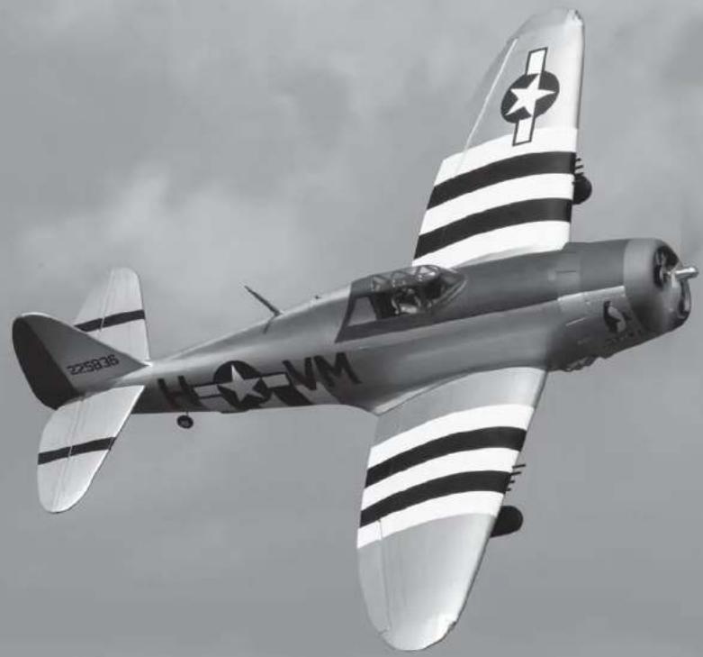
natural_image
Black-and-white photo of a vintage American military aircraft in flight with stripes and insignia, no visible text or symbols on the aircraft body.Instruction Manual
Bedienungsanleitung
All instructions, warranties and other collateral documents are subject to change at the sole discretion of Horizon Hobby, LLC. For up-to-date product literature, visit horizonhobby.com and click on the support tab for this product. The following terms are used throughout the product literature to indicate various levels of potential harm when operating this product:
Meaning of Special Language
WARNING: Procedures, which if not properly followed, create the probability of property damage, collateral damage, and serious injury OR create a high probability of superficial injury.
CAUTION: Procedures, which if not properly followed, create the probability of physical property damage AND a possibility of serious injury.
NOTICE: Procedures, which if not properly followed, create a possibility of physical property damage AND a little or no possibility of injury.
WARNING: Read the ENTIRE instruction manual to become familiar with the features of the product before operating. Failure to operate the product correctly can result in damage to the product, personal property and cause serious injury.
This is a sophisticated hobby product. It must be operated with caution and common sense and requires some basic mechanical ability. Failure to operate this Product in a safe and responsible manner could result in injury or damage to the product or other property. This product is not intended for use by children without direct adult supervision. Do not attempt disassembly, use with incompatible components or augment product in any way without the approval of Horizon Hobby, LLC. This manual contains instructions for safety, operation and maintenance. It is essential to read and follow all the instructions and warnings in the manual, prior to assembly, setup or use, in order to operate correctly and avoid damage or serious injury.
AGE RECOMMENDATION: NOT FOR CHILDREN UNDER 14 YEARS. THIS IS NOT A TOY.
□ USING THE MANUAL
This manual is divided into sections to help make assembly easier to understand.
□ SAFETY WARNINGS AND PRECAUTIONS
Read and follow all instructions and safety precautions before use. Improper use can result in fire, serious injury and damage to property.
Components
Use only with compatible components. Should any compatibility questions exist, please refer to the product instructions, component instructions or contact the appropriate Horizon Hobby office.
Flight
Fly only in open areas to ensure safety. It is recommended fl ying be done at radio control fl ying fi elds. Consult local ordinances before choosing a fl ying location.
Propeller
Keep loose items that can become entangled in the propeller away from the prop. This includes loose clothing or other objects such as pencils and screwdrivers. Keep your hands away from the propeller as injury can occur.
Batteries
Always follow the manufacturer's instructions when using and disposing of any batteries. Mishandling of Li-Po batteries can result in fi re causing serious injury and damage.
Small Parts
This kit includes small parts and should not be left unattended near children as choking and serious injury could result.
SAFE OPERATING RECOMMENDATIONS
- Inspect your model before every flight to ensure it is airworthy.
- Be aware of any other radio frequency user who may present an interference problem.
• Always be courteous and respectful of other users in your selected flight area. - Choose an area clear of obstacles and large enough to safely accommodate your flying activity.
- Make sure this area is clear of friends and spectators prior to launching your aircraft.
- Be aware of other activities in the vicinity of your flight path that could cause potential conflict.
- Carefully plan your flight path prior to launch.
- Abide by any and all established AMA National Model Aircraft Safety Code.
BEFORE STARTING ASSEMBLY
- Remove parts from bag.
- Inspect fuselage, wing panels, rudder and stabilizer for damage.
- If you find damaged or missing parts, contact your place of purchase.
- Charge transmitter and receiver batteries.
• Center trims and sticks on your transmitter. - For a computer radio, create a model memory for this particular model.
- Bind your transmitter and receiver, using your radio system's instructions.
IMPORTANT: Rebind the radio system once all control throws are set. This will keep the servos from moving to their endpoints until the transmitter and receiver connect. It will also guarantee the servo reversal settings are saved in the radio system.
FAA INFORMATION
If you own this product, you may be required to register with the FAA. For up-to-date information on how to register with the FAA, please visit https://registermyuas.faa.gov/. For additional assistance on regulations and guidance on UAS usage, visit knowbeforeyoufl y.org/.
BUILDING PRECAUTIONS
During assembly, we recommend resting the parts on a soft surface such as a soft towel to help prevent denting the sheeting.
HINWEIS
Use the 3-view drawing at the back of this manual to determine the amount of space required to transport and store your model. The model can be disassembled, so the amount of room necessary can vary. We recommend the use of a wing bag to help protect these surfaces during transport and storage. The control horns and linkages can also cause damage to nearby surfaces even when placed in storage bags. Always place surfaces so the tops are together to prevent damage from the control horns and linkages.
□ PRINTED COVERING NOTES
- The covering used on your model has the coloring and markings printed directly on the covering.
- The covering has a self-adhesive backing, and it is not recommended to use heat as it may damage the covering.
- Use only mild cleaning agents on the printed fi nish. Denatured alcohol is the most aggressive agent we recommend, but test on an inconspicuous area fi rst. Prolonged use will remove the paint.
- Use tape with care. Anything other than low-tack tape can remove the fi nish, particularly on edges.
- Avoid contact with raw fuel, especially alcohol-based fuels containing nitro methane.
- Remove exhaust residue as soon as practical to avoid staining or damaging of the fi nish.
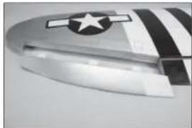
There are two areas on your aircraft that will receive wear under normal use. The fi rst area is where the cowling fi ts over the fuselage hatch, and where the wing fi ts into the fuselage. Placing a piece of clear tape on the wing where it fi ts into the fuselage, and on the hatch underneath the cowling, will reduce the wear on the covering in these areas. Sanding the inside of the cowling smooth will also help in preventing wear of the covering under the cowling.
- Use a piece of low-tack tape to hold the aileron in position. This will keep the aileron in position while aligning the II ap.
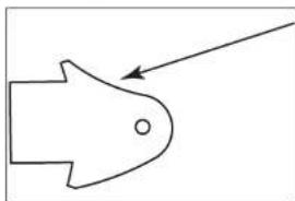
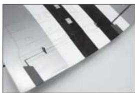
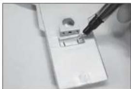
- Locate the two fl ap control horns. When installed, the concaved portion of the horn (as indicated in the drawing) will face toward the top of the fl aps.
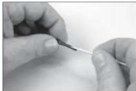
- Use a pin vise and 1/16-inch (1.5mm) drill bit to remove the paint from the hole in the fl ap control horn for the clevis. Prepare all the control horns at this time.
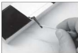
- Use medium-grit sandpaper to remove the paint from the fl ap control horn where it fi is into the fl ap. Clean the sanded area using a paper towel and isopropyl alcohol to remove any debris or oils. Removing the paint provides the surface texture necessary for the epoxy to bond to.
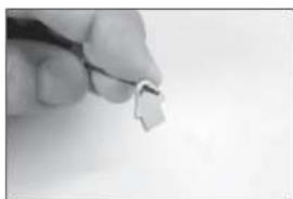
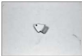
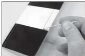
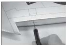
- Remove the fl ap from the wing. Run your fi nger down the leading edge of the fl ap to locate the area for the fl ap control horn. Use a hobby knife and #11 blade to remove the covering, exposing the slot for the control horn. Use 15-minute epoxy to glue the fl ap control horn in position. Remove any excess epoxy using a paper towel and isopropyl alcohol.
1.

natural_image
Close-up of a white plastic object with a gray rectangular indentation on the side (no visible text or symbols)2.
natural_image
Simple line drawing of a fish-like shape with an arrow pointing to its body (no text or symbols)3.
natural_image
Close-up of a hand holding a small white object with a thin black line, against a plain background (no text or symbols visible)4.
natural_image
Simple sketch of a small object on a plain surface (no text or symbols)5.
natural_image
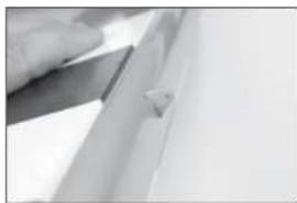
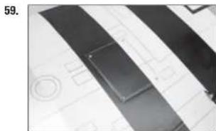
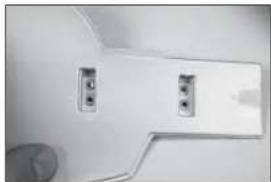
Close-up of a hand holding a flat blade over a surface, with no visible text or symbols- Run your finger down the lower surface leading edge of the fl ap to locate the areas for the fl ap hinges. Use a hobby knife and #11 blade to remove the covering, exposing the holes for the fl ap hinges. Test fl t the hinges to the fl ap. Do not use any adhesives now. Slide the hinge into position. Position as shown, checking to make sure it can move freely.
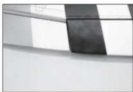
- Run your fl nger down the lower surface trailing edge of the wing to locate the areas for the fl ap hinges. Use a hobby knife and #11 blade to remove the covering, exposing the holes for the fl ap hinges. Check the fl t of the fl ap to the wing. The top of the fl ap will align to the top of the wing. It will also line up with the aleron. The fl ex point of the hinges will align with the hinge line of the fl aps when installed properly. Test the operation of the fl ap to make sure the hinges are properly aligned and the fl ap movies freely.
- Apply a small amount of petroleum jelly to the fl ex point of the hinge to prevent epoxy from entering the hinge.
→ Use care to only apply the petroleum jelly to the flex point. If applied to the hinge portion, it could cause the epoxy not to adhere to the hinge, resulting in a poor glue joint.
The flaps must be positioned to the wing before the epoxy begins to cure. Make sure to read through all the steps before mixing any epoxy. Glue only one flap at a time to allow enough working time to properly install the hinges.
→ Use 15-minute or 30-minute epoxy to allow enough working time during the hinge installation.
- Remove the fl ap from the wing and remove the hinges. Apply epoxy into each of the holes in the fl ap.
Do not use an excessive amount of epoxy when gluing the hinges so that it expels from the hinge. Also make sure to use enough epoxy so it securely adheres the hinge to the surfaces.
6.
natural_image
Close-up of a metallic rectangular object with a black horizontal line, no visible text or symbols7.
natural_image
Close-up of a striped fabric or fabric with a small black-and-white object attached (no visible text or symbols)8.

natural_image
Close-up of hands holding a pen tip, no visible text or symbols9.
natural_image
Close-up of a hand holding a pen writing on a black and white object (no visible text or symbols)-
Apply epoxy to each hinge where it will be inserted into the flap. Insert the hinges as shown in Step 6.
-
Apply epoxy to each hinge where it will be inserted into the wing.
-
Apply epoxy into each of the holes in the wing.
-
Fit the fl ap to the wing as shown in Step 7. Check that the fl ap can move freely and the hinges are all aligned properly. Use low-tack tape to hold the fl ap in position until the epoxy fully cures.
-
Use a paper towel and isopropyl alcohol to remove any excess epoxy before it can fully cure. Use care not to get epoxy in the moving part of the hinge or between the fl ap and wing. Continue once the epoxy has fully cured for both sets of fl ap hinges.
→ Repeat this section for the remaining flap installation.
10.
natural_image
Close-up of hands holding a small tool, no visible text or symbols11.
natural_image
Close-up of a gloved hand holding a small tool, with a dark rectangular object in the background (no visible text or symbols)12.

natural_image
Close-up of a hand holding a small white object over a metallic surface (no visible text or symbols)13.
natural_image
Abstract geometric pattern with diagonal striped and rectangular shapes (no text or symbols)14.

natural_image
Close-up of a hand holding a small object over a document or paper (no visible text or symbols)-
Remove the tape and aileron from the wing panel.
-
Use a pin vise and 1/16-inch (1.5mm) drill bit to drill a hole in the center of each hinge slot. Drill the hole 1/4-inch (6mm) deep into the wood. Drill holes in both the wing and alleron hinges slots now.
-
Check the gap between the wing tip and aileron.
-
Check the gap between the flap and aileron. The gaps in Steps 16 and 17 must be equal before applying CA to the hinges.
→ When the flap is lowered and the aileron is in the full down position, there may be some interference between the flap and aileron. In flight, the aileron will not drop down far enough to interfere with the flap.
- Apply thin CA to the top of each of the hinges. Make sure to fully soak the hinges so the CA can wick into the hinge and bond to the surrounding wood.
→ Use thin CA so it wicks into the hinge. A thicker CA will not wick into the hinge properly. Do not to allow the CA to run over the covering on the wing and aileron.
15.
natural_image
Close-up of a metallic object with a star symbol and curved edge, no visible text or markings16.
natural_image
Close-up of a hand holding a small object over a white architectural or mechanical component (no visible text or symbols)17.

natural_image
Close-up of a computer mouse with a curved handle and grid pattern (no visible text or symbols)18.
natural_image
Abstract grayscale geometric pattern with diagonal stripes and a dark central band (no text or symbols)19.

natural_image
Close-up of a hand holding a pen over a grid of paper with a star symbol in the background (no readable text or symbols)- Allow the CA to cure for 10 to 15 minutes. Gently pull on the fixed surface and control surface to make sure the hinges are glued securely. If not, apply additional CA to secure each of the hinges.
- Move the alleron through its range of throw to break in the hinges.
- Check both the up and down movement of the hinges before proceeding.
- Run your fl nger along the bottom of the aileron to locate the area for the fl ap control horn. Use a hobby knife and #11 blade to remove the covering, exposing the slot for the control horn. Place tape around the slot in the aileron for the aileron control horn.
-
Locate the two silver aileron control horns. Use medium-grit sandpaper to remove the paint from the bottom of the control horn where it fits into the aileron.
-
- Apply epoxy to the area of the control horns that fi ts into 25.
-
Apply epoxy to the area of the control horns that fi ts into the slots. Use enough epoxy so the control horns will be fully bonded to the fi xed surfaces.
-
Remove the control horns from the control surfaces. Apply epoxy to the slot in the aileron and flap. Make sure the epoxy gets into the slot for a good bond between the surfaces and control horn.
-
Before the epoxy fully cures, remove the tape from around the control horn. This will allow the epoxy to flow around the control horn, creating a small fi let between the control horn and surface for a fi nished look and secure bond.
→ Repeat this section for the remaining aileron installation.
☐ AILERON SERVO INSTALLATION 28.
- Use a hobby knife or other sharp tool to puncture the covering at the screw holes that will secure the cover to the wing. Also remove the covering for the aileron servo arm in the cover.
- Place the cover back into position. Use a pin vise and 1/16-inch (1.5mm) drill bit to drill the mounts for the servo covers. Use care not to drill through the covering on the top of the wing.
15/16 inch (24mm)
-
Thread an M2 x 10 sheet metal screw into each hole using a #1 Phillips screwdriver. Remove the screws before proceeding.
-
Apply a small amount of thin CA to harden the threads made in the previous step. Allow the CA to fully cure before installing the aileron servo cover.
→ Prepare the flap servo covers at this time as well.
-
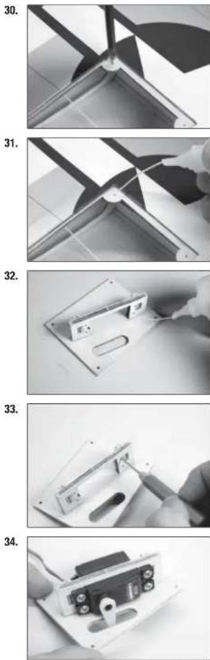
Check that the vertical servo mount is glued securely to the servo cover. If the mount is not secure, use a small amount of medium CA or epoxy to securely adhere the servo mount to the cover.
-
Use a pin vise and 5/32-inch (2mm) drill bit to drill the holes for the servo mounting screws. Make sure to harden the holes using the technique outlined in Steps 30 and 31. Use the screws provided with the servo and a #1 Phillips screwdriver when installing the screws.
-
Secure the servo to the cover using a #1 Phillips screwdriver and the screws provided with the servo. Center the servos, then secure the servo arm so it is perpendicular to the servo centerline. Use side cutters to remove any arms that do not protrude to the outside of the cover.
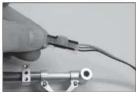
- Secure a 12-inch (300mm) servo extension to the servo using a commercially available fastener (SPMA3054).
- Tie or tape the string located inside the wing to the end of the servo lead.
- Use the string to pull the servo lead through the wing and out at the root.
- Secure the servo to the wing using four M2 x 10 sheet metal screws. Use a #1 Phillips screwdriver to tighten the screws.
-
Slide a silicone tube on the clevis. Thread the clevis on the 4718 inch (124mm) pushrod. Allow 1/16 inch (1.5mm) of the threads on the pushrod protrude between the forks of the clevis.
-
natural_image
Close-up of a hand holding a small electronic component with wires, no visible text or symbols
natural_image
Close-up of a hand inserting a small electronic component into a device (no visible text or symbols)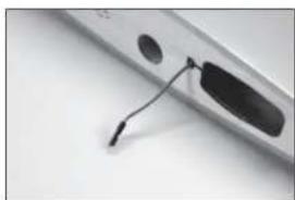
natural_image
Close-up of a metallic electronic device with a black cable inserted, showing no visible text or symbols.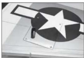
natural_image
Close-up of a mechanical device with a star-shaped component and a rectangular block, no visible text or symbols.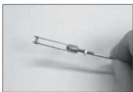
natural_image
Close-up of a hand holding a small metallic object with a looped end (no visible text or symbols)- Attach the clevis to the inside hole on the aileron control horn.
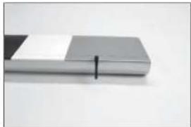
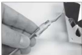
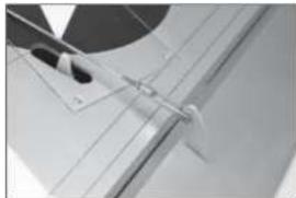
- Center the aileron servo using the radio system. With the aileron centered, use a felt-tipped pen to mark the pushrod where it crosses the outer hole of the servo arm.
- Remove the clevis from the control horn. Use pliers to bend the pushrod at the mark made in the previous step.
- Insert the pushrod into the outer hole on the servo arm. It may be necessary to enlarge the hole using a pin vise and 5/64-inch (2mm) drill bit. Reattach the clevis to the control horn.
-
Slide the pushrod keeper on the pushrod wire.
-
natural_image
Close-up of a sewing machine needle stitching a metal wire (no text or symbols visible)
natural_image
Close-up of a hand using a pen to draw a chart with a triangular overlay (no visible text or symbols)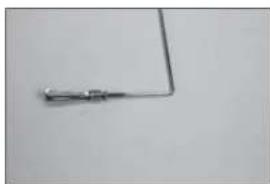
natural_image
Simple electrical circuit lines without any symbols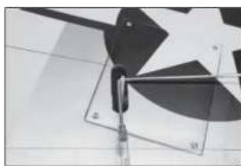
natural_image
Close-up of a metallic pinwheel with mounting bracket and grid pattern (no visible text or symbols)
natural_image
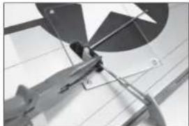
Close-up of a mechanical component with a curved bracket and mounting base (no visible text or symbols)- Slide the keeper tightly against the servo arm. Use pliers to snap the keeper on the pushrod wire.
- Use side cutters to trim the pushrod wire 1/16 inch (1.5mm) from the pushrod keeper.
- Check the operation of the aileron using the radio system. Trim the servo cover if the keeper or pushrod wire hits the cover during the operation of the aileron. Slide the clevis retainer over the forks of the clevis. Apply a drop of threadlock on the threads near the clevis, then tighten the nut against the clevis using pliers.
→ Repeat this section for the remaining aileron servo installation.
FLAP SERVO INSTALLATION
- Slide a silicone tube on the clevis. Thread the clevis on the 4^7/_8 inch (124mm) pushrod. Allow 1/16 inch (1.5mm) of the threads on the pushrod protrude between the forks of the clevis.
-
Attach the clevis to the fl ap control horn.
-
natural_image
Close-up of a mechanical component with angular blades and a ruler, no visible text or symbols
natural_image
Close-up of a mechanical tool interacting with a circular component, showing alignment marks (no visible text or symbols)
natural_image
Close-up of aircraft wing structure with star symbol (no text or labels visible)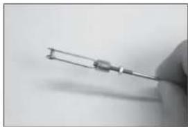
natural_image
Close-up of a hand holding a small electronic component (no visible text or symbols)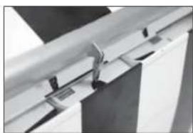
natural_image
Close-up of a metallic mechanical bracket or hinge assembly (no visible text or symbols)- Secure an 3-inch (75mm) servo extension to the servo using a commercially available fastener (SPMA3054). Secure the servo in the wing using a #1 Phillips screwdriver and the screws provided with the servo. Make sure the servo output faces toward the leading edge of the wing. Pull the fl ap servo extension through the wing so it exits near the aileron servo lead.
→ The servo arm for the flap servos will point toward the right wing tip.
-
Center the flap servo using the radio system. Attach the servo arm to the servo using the hardware included with the servo. Remove any arms that may interfere with the operation of the servo.
-
Use a pin vise and 5/64-inch (2mm) drill bit to enlarge the hole in the servo arm that is 1/2-inch (12mm).
-
Place the fl ap in the UP fl ap position. We recommend using low-tack tape to keep the fl ap in position during the next few steps.
-
natural_image
Exterior view of a modern office building (no signage)
natural_image
Pure geometric diagram with curved and straight lines, no text or symbols present
natural_image
Interior view of a room with furniture and doorways (no visible text or symbols)
text_image
1/2-inch (13mm)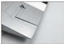
natural_image
Close-up of a white mechanical component with a diagonal seam and a small triangular feature (no text or symbols visible)-
Use the radio system to move the servo to the UP fl ap position. Use a felt-tipped pen to mark the pushrod where it crosses the outer hole in the servo arm.
-
Remove any tape holding the fl ap in position. Connect the linkage to the servo arm using a pushrod keeper. Use the radio system to center the fl ap servo.
→ Remove the screw securing the servo arm to make adjustments to the linkage in the next step.
-
Make sure the flap is in the MID flap position according to the control throws in this manual. Adjust the linkage as necessary to set the throw.
-
Move the servo to the FULL fl ap position using the radio system. Adjust the throws in the radio system to obtain the measurements listed in the manual for the full fl ap position.
-
Move the servo to the UP fl ap position using the radio system. Adjust the throws at the radio system to bring the fl ap in alignment with the trailing edge of the wing.
-

natural_image
Close-up of a hand using a screwdriver to adjust or install electronic components in a circuit board (no visible text or symbols)
natural_image
Interior view of a mechanical or electronic device with no visible text, numbers, or symbols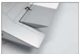
natural_image
Close-up of a white plastic sheet with a metal bracket and angled edge (no text or symbols visible)
natural_image
Close-up of a metallic architectural component with angled surfaces and a small bracket (no text or symbols visible)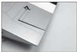
natural_image
Close-up of a white mechanical component with a diagonal line and circular mark (no visible text or symbols)-
Secure the servo arm to the servo. Secure the clevis to the control horn following the same procedures as the aileron linkage. Always use threadlock on metal-to-metal fasteners. Secure the flap servo cover in position using four 2mm x 10mm sheet metal screws.
-
Use canopy glue to glue the navigation lights in position at the wing tips. The left navigation light is red, the right is green.
→ Do not use CA when attaching the navigation lights and covers as it will fog the covers as it cures.
- Use canopy glue to glue the covers to the wing tips. Use low-tack tape to hold the covers in position until the adhesive fully cures.
→ Repeat this section for the remaining flap servo installation.
FIXED GEAR INSTALLATION
→ Skip this section of the manual if you are installing the optional retracts.
-
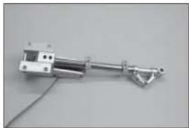
Use a fl at fi le to make a 1/2-inch long fl at area on the strut. The setscrew from the mount will tighten on the fl at, preventing the gear from rotating.
-
Attach the landing gear strut in the mount. Use threadlock on the setscrew before tightening it on the fl at area on the strut. Use a 2mm hex wrench to tighten the setscrew.
natural_image
Abstract geometric pattern with diagonal black bands and grid lines on a light background (no text or symbols)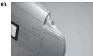
natural_image
Close-up of a metallic vehicle's side profile with no visible text or symbols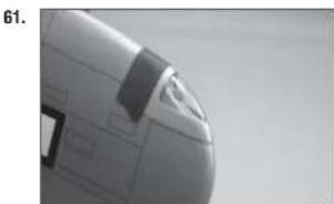
natural_image
Close-up of a jet aircraft nose section (no visible text or symbols)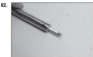
natural_image
Close-up of a metallic screwdriver tip with no visible text or markings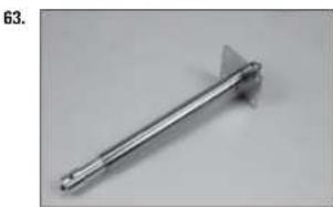
natural_image
Metal tool with a triangular handle and pointed tip, shown against a plain background (no text or symbols visible)-
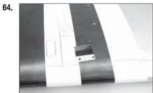
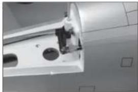
Use a hobby knife and #11 blade to remove the covering from the mounting rails in the wing. Trim the covering inside the opening.
-
Attach the strut mount to the wing using four M3 x 25 socket head cap screws, four M3 washers and four M3 lock washers. Place a drop of threadlock on each screw before installing them. Tighten the screws using a 2.5mm hex wrench.
-
Place the landing gear door mount near in the opening in the landing gear door. Use a felt-tipped pen to transfer the locations for the mounting screws on the gear door.
-
Use a drill and 1/8-inch (3mm) drill bit to drill the locations for the gear door mounting screws.
-
Slide the landing gear door mounts on the landing gear struts. The position of the mounts will be adjusted during the landing gear door installation.
natural_image
Close-up of a metallic panel with white and black bands, showing internal cutouts and a small object (no text or symbols visible)
natural_image
Close-up of a sewing machine needle stitching fabric (no visible text or symbols)
natural_image
Close-up of a hand using a tool to cut a small electronic component (no visible text or symbols)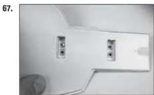
natural_image
Close-up of a white electronic device with two connected ports and a curved panel (no visible text or symbols)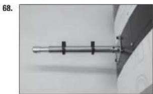
natural_image
Close-up of a metallic cylindrical object with black connectors, mounted on a wall (no visible text or symbols)-
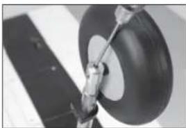
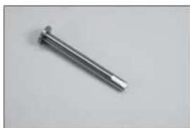
Slide the M5 washer on the M5 x 45 socket head cap screw. Slide the screw into the wheel. Make sure the wheel rotates freely on the screw. If not, use a hobby knife with a #11 blade or 5mm drill bit to remove any fl ashing that may be interfering with the rotation of the wheel on the screw.
-
Slide the M5 plastic spacer on the screw.
-
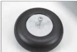
Thread the screw into the landing gear strut. Make sure the wheel can rotate freely on the screw. Tighten the setscrew using a 2mm hex wrench to secure the screw.
→ Always use threadlock on metal-to-metal fasteners.
→ It may be necessary to add an additional washer to provide clearance between the wheel and strut if the wheel rubs against the strut.
-
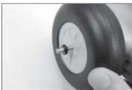
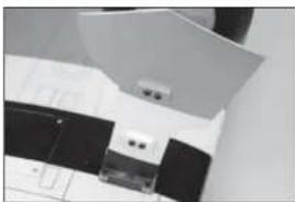
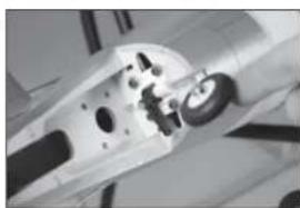
Position the gear door mounts so there will be a 1/8-inch (3mm) gap between the gear door and wing. Use four M3 x 6 button head screws to attach the gear doors to the gear door mounts.
-
Check that there is a slight amount of toe-in (roughly 1-degree). Adjustments can be made by loosening the two setscrews on the strut near the mount using a 1.5mm hex wrench.
→ The amount of toe-in shown has been exaggerated so it can be seen clearly in the photo.
→ Always use threadlock on metal-to-metal fasteners.
→ Repeat this section for the remaining fixed gear installation.
69.
natural_image
Close-up of a black circular object with a metallic knob, possibly a knob or knob (no text or symbols visible)70.
natural_image
Close-up of a hand holding a small black tire with a metallic screw (no visible text or symbols)71.
natural_image
Close-up of a mechanical component with a circular head and lever mechanism (no visible text or symbols)72.
natural_image
Close-up of a mechanical component with no visible text or symbols73.
natural_image
Close-up of a dark, oval-shaped object on a white surface with a grid background (no visible text or symbols)□ RETRACT INSTALLATION
→ Skip this section of the manual if the fixed gear has been installed on your model.
-
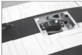
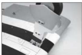
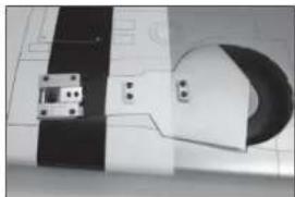
Use a hobby knife and #11 blade to remove the covering from the retract openings in the wing. Trim the covering inside the opening.
-
Place the landing gear door mount near in the opening in the landing gear door. Use a felt-tipped pen to transfer the locations for the mounting screws on the gear door.
-
Use a drill and 1/8-inch (3mm) drill bit to drill the locations for the gear door mounting screws.
-
Slide the gear door mounts on the retract strut. Insert the retract strut into the retract frame. Secure the strut by tightening the two setscrews using a 2mm hex wrench.
→ The gear door mount positions will be adjusted later in this section of the manual.
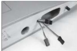
- Secure a 9-inch (230mm) servo extension to the lead on the retract.
74.
natural_image
Close-up of a white mechanical component with a circular opening and metallic fittings (no visible text or symbols)75.
natural_image
Close-up of a white electronic component being inserted with a pen, no visible text or symbols76.
natural_image
Close-up of a white plastic electronic component with two metallic pins (no visible text or symbols)77.
natural_image
Mechanical device with articulated arm and connecting rod, no visible text or symbols78.
natural_image
Close-up of a hand holding a cable with a connector, no visible text or symbols- Fit the retract frame to the wing. Guide the servo extension through the wing, exiting the same location as the flap and aileron servo leads.
→ Make sure to mark each servo lead so they can be identified easily when connection them to the receiver.
- Secure the retract in the wing using the hardware included with the retract.
→ Always use threadlock on metal-to-metal fasteners.
→ It may be necessary to use the spacers included with the retracts to make sure there is no torsional stress on retract frame when tightened into position. Torsional stress can cause intermittent operation of the retract unit.
-
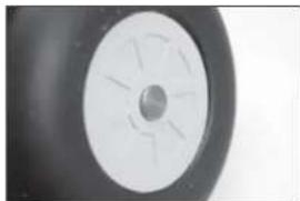
Use a fl at fi le to make a 1/4 inch (6mm) wide fl at area on the retract axle.
-
Slide the axle into the wheel. Make sure the wheel rotates freely on the axle. If not, use a hobby knife with a #11 blade or 5mm drill bit to remove any fl ashing that may be interfering with the rotation of the wheel on the axle.
-
Place a nylon spacer on the axle.
79.
natural_image
Close-up of a computer monitor with a black plastic cover and attached cables (no visible text or symbols)80.

natural_image
Close-up of a mechanical assembly with a rotating component and a circular housing (no visible text or symbols)81.
natural_image
Metal mechanical component with a pointed tip, isolated on a plain background (no text or symbols visible)82.
natural_image
Close-up of a black and white wheel rim with a central hole (no text or symbols visible)83.
natural_image
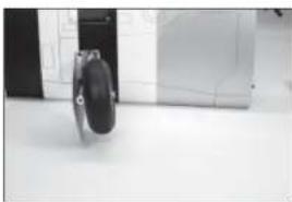
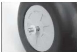
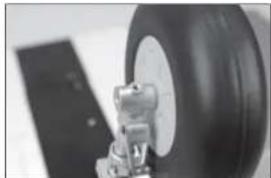
Close-up of a car wheel rim with a small valve or knob on the rim (no visible text or symbols)- Slide the axle into the retract strut. Tighten the setscrew to secure the axle to the strut. Make sure the wheel can rotate freely on the axle.
→ Always use threadlock on metal-to-metal fasteners.
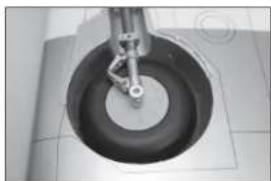
- Check the operation of the retract using the radio system. The wheel must be centered in the opening. If not, loosen the mounting screws and adjust as necessary.
→ Spacers have been included with the retracts. Use these to adjust the positioning of the retract to allow the wheel to retract without interfering with the wheel well. Once adjusted, check that there is no torsional stress on retract frame.
-
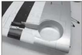
Attach the landing gear doors to the gear door mounts using the hardware included with the retracts. The mounts should be easily moved so the gear door can be positioned in the following step.
-
Use the radio system to cycle the retracts. Position the gear doors so they align with the recess in the wing. It may be necessary to cycle the gear a few times to correctly position the gear doors. Make sure there is no binding during the operation of the retract, which could cause it to stop during its operation. Tighten all the hardware to complete the retract installation.
84.
natural_image
Close-up of a mechanical component with a large tire and attached bracket (no visible text or symbols)85.
natural_image
Close-up of a mechanical component with a circular base and central shaft (no visible text or symbols)86.
natural_image
Close-up of a mechanical assembly with no visible text or symbols87.
natural_image
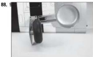
Close-up of a mechanical component with black and white striped pattern (no visible text or symbols)- Check that there is a slight amount of toe-in (roughly 1-degree). Adjustments can be made by loosening the setscrews on the retract frame. After adjusting the toe in, check the alignment of the wheel as it retracts into the wheel well to verify that it is not binding in the up position.
→ The amount of toe-in shown has been exaggerated so it can be seen clearly in the photo.
→ Always use threadlock on metal-to-metal fasteners.
→ Repeat this section for the remaining retract installation.
natural_image
Close-up of a mechanical device with a circular component and a curved arm, placed on a surface (no visible text or symbols)-
Slide the wing panel into position. Guide the fl ap and aileron leads into the fuselage.
-
Secure the wing to the fuselage using the 1/4-20 x 2 nylon wing bolt.
□ STABILIZER AND RUDDER INSTALLATION
-
Move the canopy latch toward the front of the fuselage.
-
Lift the canopy hatch from the fuselage at the rear. Slide the hatch back and remove it from the fuselage. Set it aside in a safe location.
-
Slide the wing tube into the wing tube socket.
natural_image
Close-up of a hand pressing down on a curved surface with grid lines (no text or symbols visible)
natural_image
Close-up of a hand interacting with a mechanical component (no visible text or symbols)
natural_image
Close-up of a metallic electronic device with a metallic clip and mounting holes (no visible text or symbols)-
Use a razor saw to remove the tail post at the rear of the fuselage. Use medium grit sandpaper to sand the area fl at so the stabilizer will fi t into the opening.
-
Place the stabilizer in position. The black stripe on the stabilizer will face toward the top of the fuselage.
-
Center the stabilizer on the fuselage.
natural_image
Interior view of a bathroom with tiled walls and a bathtub (no visible text or symbols)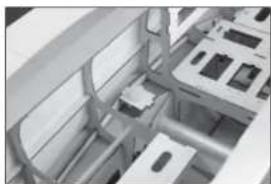
natural_image
Interior view of a modern office or retail space with furniture and display areas (no visible text or symbols)
natural_image
Close-up of a metallic mechanical component with no visible text or symbols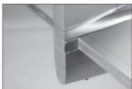
natural_image
Close-up of metallic structural beams or joints (no text or symbols visible)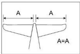
text_image
A A A=A-
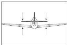
Stand back 8-10 feet (2-3 meters) and check that the stabilizer is aligned with the wing. Lightly sand the stabilizer saddle on the fuselage to correct any misalignment.
-
Measure from each wing tip to each stabilizer tip. Adjust the stabilizer so the measurements are the same for both sides.
-
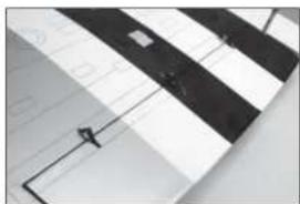
Use a felt-tipped pen to transfer the fuselage outline onto the bottom of the stabilizer.
-
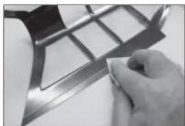
Use a ruler and carefully cut the covering 1/8 inch (3 mm) inside the line drawn on the bottom of the stabilizer to remove the covering from the center of the stabilizer. Use care not to cut into the underlying wood, weakening the stabilizer.
-
Mix 1/2 ounce (15ml) of 30-minute epoxy. Use an epoxy brush to apply epoxy to the exposed wood on the bottom of the stabilizer.
-
natural_image
Simple line drawing of an airplane viewed from above, showing aerodynamic airflow direction (no text or symbols)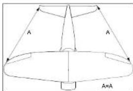
text_image
A A A=A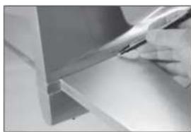
natural_image
Close-up of a hand holding a pen over a white surface, possibly part of a technical or architectural component (no visible text or symbols)
natural_image
Close-up of a rolled-up document or scroll with a hand holding it (no visible text or symbols)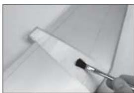
natural_image
Close-up of a hand holding a paintbrush touching a white rectangular object (no text or symbols visible)-
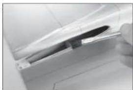
Use an epoxy brush to apply epoxy to the stabilizer mounting surface for the stabilizer.
-
Position the stabilizer back on the fuselage and check its alignment. Use a paper towel and a small amount isopropyl alcohol to remove any excess epoxy from the fuselage and stabilizer before the epoxy fully cures. Allow the epoxy to fully cure before proceeding.
→ Check the position of the stabilizer repeatedly during the curing process to make sure it has not moved.
→ The wing can be removed from the fuselage now.
-
Locate the two silver elevator control horns. Use medium-grit sandpaper to remove the paint from the bottom of the control horn where it fi ts into the elevator.
-
Run your finger along the bottom (side without the black stripe) of the elevator to locate the area for the control horns. Use a hobby knife and #11 blade to remove the covering, exposing the slot for the control horn. Use 15-minute epoxy to glue the elevator control horns in the elevators. Follow the technique outlined in the aileron control horn installation.
-
Fit the elevators to the stabilizer. Align the tips of the elevators to the stabilizer. Glue the hinges following the procedure outlined earlier for the alleron hinges.
-
natural_image
Close-up of a car door handle and seat area (no visible text or symbols)
natural_image
Close-up of a metallic structural joint or bracket detail (no text or symbols visible)
text_image
15/16 inch (24mm)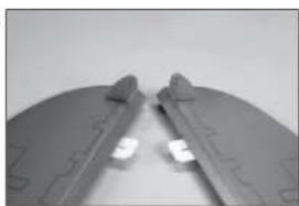
natural_image
Close-up of two gray plastic components with cutouts and mounting holes (no text or symbols visible)
natural_image
Close-up of a metallic cylindrical object with a curved edge and a flat surface, possibly part of a mechanical or architectural component (no visible text or symbols)- Locate the red rudder control horn. Use medium grit-sandpaper to remove the paint from the bottom of the control horn where it fi ts into the rudder.
- Use 15-minute epoxy to glue the rudder control horn in the rudder. Follow the technique outlined in the aileron control horn installation.
- Fit the rudder to the fi n. Align the tip of the rudder to the top of the fi n. Glue the hinges following the procedure outlined earlier for the aileron hinges.
☐ ELEVATOR AND RUDDER SERVO INSTALLATION
- Use a hobby knife with a #11 blade to remove the covering from the fuselage to expose the exits for the rudder and elevator pushrods. The opposite side has only the exit for the elevator.
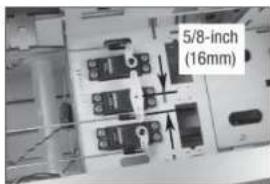
- Install the rudder and elevator servos using the hardware provided with the servos. Make sure to pre-drill the holes for the servo mounting screws, and prep them using thin CA as outlined in the aileron servo installation.
→ The rudder is the center servo.

text_image
15/16 inch (24mm)
natural_image
Close-up of a dark gray plastic component with a small protrusion on the side (no visible text or symbols)
natural_image
Close-up of a propeller blade with a small handle, no visible text or symbols
natural_image
Close-up of a white cylindrical object with a rectangular opening, possibly a vent or duct (no visible text or symbols)
natural_image
Interior view of an electronic device with multiple ports and wiring (no visible text or symbols)- Secure the receiver in the fuselage using hook and loop tape and hook and loop straps. Locate the remote receiver based on the instructions included with the receiver or radio system.
→ Make sure the receiver is securely installed if using an AS3X-equipped item. Read the instructions included with the receiver for additional mounting details. - Slide the pushrod into the pushrod tube for the elevator. Slide a clevis retainer on the clevis, then thread the clevis on the pushrod. Connect the clevis to the outer hole of the elevator control horn.
- Center the elevator servo using the radio system. Installing the pushrod follows the same procedure as the aileron and flap linkages. The pushrod connects to the hole of the elevator servo arm that is 1/2-inch (13mm) from the center of the servo arm.
- Install the remaining elevator pushrod.
-
Connect the pushrod to the elevator servo. Use Step 114 for more details to connect the pushrod to the elevator servo.
-
natural_image
Interior view of an electronic device with visible circuit boards and wiring (no readable text or symbols)
natural_image
Close-up of a curved mechanical component with internal wiring and mounting features (no visible text or symbols)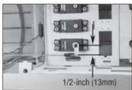
text_image
1/2-inch (13mm)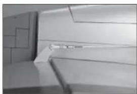
natural_image
Interior view of a modern kitchen or bathroom area with tiled walls and appliances (no visible text or symbols)
natural_image
Interior view of an electrical enclosure with visible circuitry and wiring (no text or symbols)-
Complete the installation be installing the rudder pushrod. Make sure to slide all clevis retainers into position, and use threadlock on all metal-to-metal fasteners.
-
Connect the rudder pushrod at the servo. Use the hole in the arm that is 5/8-inch (16mm) from the center of the servo arm.
☐ TAIL WHEEL ASSEMBLY INSTALLATION
-
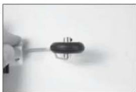
Slide the metal bushing on the tail wheel wire, then the tail wheel. Apply thread lock to the M3 setscrew. Secure the tail wheel to the wire using a 3mm wheel collar and M3 setscrew. Tighten the setscrew using a 1.5mm hex wrench.
-
Remove the tail wheel hatch from the fuselage.
→ A plastic hatch has been included with this model for modelers that may install an optional retractable tail wheel. Installation of a retractable tail wheel is at the discretion of the modeler and not covered in this manual. Trimming of the hatch will be required to allow operation of the tail wheel retract mechanism.
- Secure the tail wheel mount in the fuselage using M3 x 12 socket head cap screws and M3 washers. Place a drop of threadlock on the screws before installing them in position. Use a 2.5mm hex wrench to tighten the screws.
117.
natural_image
Close-up of a jet engine component with visible blades and mounting bracket (no text or symbols)118.
text_image
5/8-inch (16mm)119.
natural_image
Close-up of a hand holding a black electrical plug (no visible text or symbols)120.
natural_image
Close-up of a hand holding a metallic cylindrical device with a small inset showing internal components (no visible text or symbols)121.
natural_image
Close-up of a mechanical component with visible gears and shafts (no text or symbols)- Remove the nut from the pushrod and install it into the tube from inside the fuselage. Thread the nut on the pushrod and prepare the clevis with a clevis retainer. Attach the clevis to the tail wheel arm. Secure the clevis and retainer.
- Attach the pushrod to the rudder servo arm using a pushrod keeper. Use the hole in the arm that is 5/8-inch (16mm) from the center of the servo arm.
→ Use the rudder trim to flight trim your model. Adjust the linkage if your model requires adjustments during taxi.
- Replace the tail wheel cover on the fuselage.
→ There may be a wooden cross bar on the front inside edge of the tail wheel cover hatch that needs to be broken away in order for the hatch to fit.
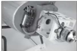
□ ELECTRIC MOTOR INSTALLATION
→ Skip to the next section if you are installing a gas or glow engine.
→ This section covers the installation of the recommended engine. Using a different engine may require changes not covered in this manual.
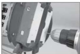
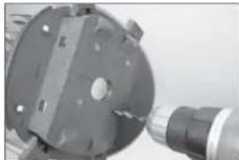
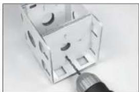
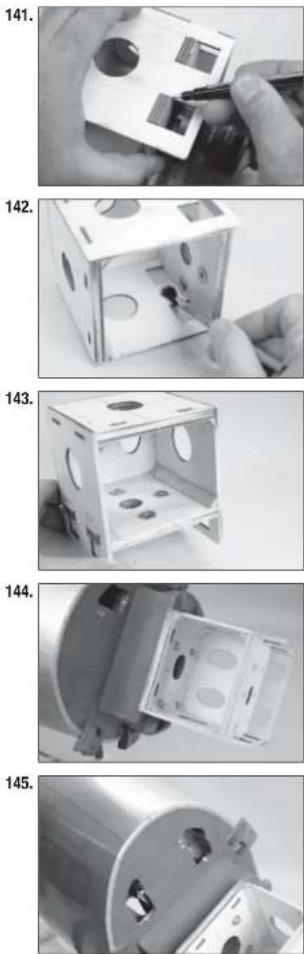
- Place the mounting template on the fuselage. Use a 5/64-inch (2mm) drill bit to drill the holes into the fuselage.
122.
natural_image
Close-up of a white plastic panel with circular cutouts and a small inset component, mounted on a ceiling (no visible text or symbols)123.

text_image
5/8-inch (16mm)124.

natural_image
Close-up of a metallic aircraft wing with a circular emblem on top (no visible text or symbols)125.
natural_image
Close-up of a mechanical component with a cylindrical shaft and housing (no visible text or symbols)-
Use a drill and 7/32-inch (5.5mm) drill bit to enlarge the holes to mount the engine.
-
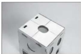
Extend the centerlines on the back (fixed portion) of the motor mounting box.
→ The front of the mount is adjustable to allow a variety of motor installation options.
- Align the centerlines on the template with the centerlines on the motor box. Use tape to secure the template to the motor box. Make sure all drill locations can be clearly seen when taping the template to the motor box.
→ Check to make sure the template is positioned properly on the motor box.
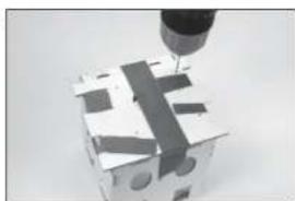
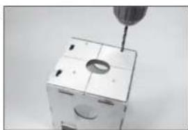
-
Use a 5/32-inch (2mm) drill bit to drill the holes in the motor box using the template as a guide.
-
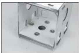
Use a drill and 7/32-inch (5.5mm) drill bit to enlarge the holes to mount the motor box to the fl rewall.
126.
natural_image
Close-up of a mechanical component with a circular housing and a cylindrical shaft (no visible text or symbols)127.
natural_image
Close-up of a white plastic cube with cutouts and mounting holes (no text or symbols visible)128.

natural_image
Close-up of a hand holding a small electronic component with a circular cutout (no visible text or symbols)129.
natural_image
Close-up of a mechanical component with a cylindrical tool inserted, showing no visible text or symbols.130.
natural_image
Close-up of a mechanical component with a screwdriver inserted into a square housing (no visible text or symbols)-
Align the X-mount on the centerlines on the fi rewall. Use a felt-tipped pen to mark the locations for the mounting positions.
-
Use a drill and 11/64-inch (5mm) drill bit to enlarge the holes to mount the engine.
-
Insert the blind nuts supplied with the motor in the back of the motor box plate.
-
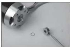
The motor shaft must be repositioned to allow the installation of the propeller adapter. Use a 1.5mm hex wrench to remove the setscrew from the collar. Remove the collar and shim from the motor shaft.
-
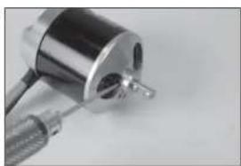
Use a 1.5mm hex wrench to remove the two setscrews that secure the motor shaft to the motor bell housing.
131.

natural_image
Close-up of hands using a screwdriver to adjust a black mechanical component (no text or symbols visible)132.
natural_image
Close-up of a small electronic component with circular cutouts and a metallic connector (no visible text or symbols)133.
natural_image
Transparent plastic cube with multiple circular holes and a central black dot (no text or symbols visible)134.
natural_image
Close-up of a metallic mechanical component with a circular hole and a separate rod-like object (no text or symbols visible)135.
natural_image
Close-up of a metallic mechanical component with threaded shaft and housing (no visible text or symbols)- Use a press to carefully reposition the motor shaft so it is flush with the face of the bell housing. Apply a drop of threadlock on each of the setscrews. Replace the setscrews and tighten them using a 1.5mm hex wrench.
→ Make sure not to damage the motor when repositioning the shaft.
-
Slide the shim on the motor shaft. Apply a drop of threadlock on the setscrew. Slide the collar on the shaft and secure it to the motor shaft using the setscrew and a 1.5mm hex wrench.
-
Attach the X-mount to the motor. Place a drop of threadlock on each of the screws provided with the motor, then use a #2 Phillips screwdriver to tighten the screws attaching the mount to the motor.
-
Attach the propeller adapter to the motor. Apply a drop of threadlock on each of the screws. Use a 2.5mm hex wrench to tighten the screws attaching the adapter to the motor.
-
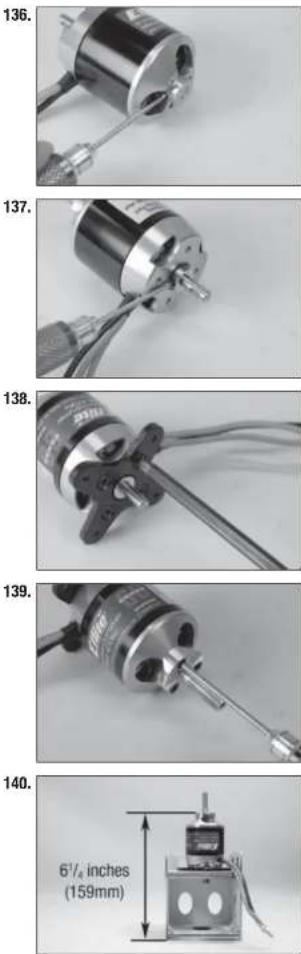
Place the motor on the sliding fi rewall. Adjust the sliding fi rewall so the measurement from the drive washer to the rear face of the motor box measures 6^1/_4 inches (159mm).
→ The mount is adjustable for a variety of motors.
- Use a felt-tipped pen to mark the location of the sliding fi rewall on the outside of the motor box.
- Remove the motor. Move the sliding fl rewall so a thin coat of 30-minute epoxy can be applied to the motor box where the plate contacts the box. Slide the plate into position. Use a paper towel and isopropyl alcohol to remove any excess epoxy.
- Once the epoxy fully cures, install the triangle stock on the inside of the motor box. Make sure to cut the triangle stock so it does not cover the blind nuts and fi ts tight into the corners of the motor box.
- Attach the motor mount to the fi rewall using four M4 blind nuts, M4 x 20 machine screws, four M4 nuts and eight M4 washers. Make sure to use threadlock on all hardware to prevent them from vibrating loose.
- Use a hobby knife to remove the openings in the sub-fl rewall to allow the leads from the speed control to enter the fuselage.
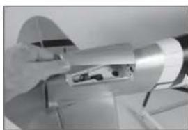
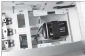
- Remove the battery tray from the fuselage using a #1 Phillips screwdriver. Secure the receiver battery in the area below the battery tray.
→ We highly recommend using a receiver battery when retracts are installed to reduce the load on the motor battery.
-
Mount the switch for the receiver in the fuselage. Secure the connection between the switch and receiver battery. Connect the switch to the receiver.
-
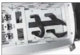
Apply hook and loop tape to the battery tray. Place two hook and loop straps through the openings in the battery tray.
→ Apply a small amount of 5-minute epoxy to the straps to secure them to the battery tray. This will prevent them from falling through the holes when the battery is removed.
-
Install the battery tray back in the fuselage using the hardware previously removed.
-
Attach the motor to the motor box using the hardware provided with the motor.
146.
natural_image
Interior view of a computer setup with monitor, keyboard, and drive unit (no visible text or labels)147.

natural_image
Close-up of a white electronic device with a black internal component and a small rectangular slot (no visible text or symbols)148.

natural_image
Close-up of two black metal bracket components mounted on a white base plate (no text or symbols visible)149.
natural_image
Close-up of a mechanical component with black 3D lettering and mounting holes (no visible text or symbols)150.

natural_image
Close-up of a mechanical device with a cylindrical component and wires, no visible text or symbols- Use hook and loop tape to mount the speed control to the fuselage. Connect the leads from the motor and speed control and secure them using tie wraps so they don't interfere with the operation of the motor. Guide the leads for the battery and receiver through the tray. Connect the servo lead from the speed control to the throttle port of the receiver.
→ A tie wrap is also recommended to prevent the speed control from moving.
- Mount the battery in the fuselage using hook and loop straps and hook and loop tape.
→ Do not cover safely warnings on the battery with hook and loop tape.
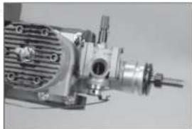
GAS ENGINE INSTALLATION
→ Skip to the section Cowling Installation if you have installed an electric power system.
→ This section covers the installation of the recommended engine. Using a different engine may require changes not covered in this manual.
- Place the mounting template on the fuselage. Use low-tack tape to keep the template held tightly in position during drilling. Use a 5/64-inch (2mm) drill bit to drill the holes into the fuselage necessary to mount your particular motor choice.
→ Make sure to verify the holes in the template align with the holes required for mounting your particular motor before drilling any holes.
151.
natural_image
Close-up of a mechanical device with internal components and wiring (no visible text or symbols)152.

natural_image
Interior view of a vehicle showing internal compartments and structural elements (no visible text or symbols)153.

natural_image
Close-up of a mechanical component with a cylindrical tool inserted, no visible text or symbols-
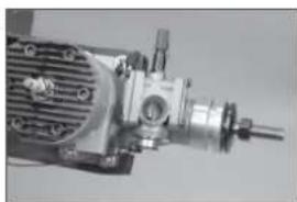
Use a drill and 7/32-inch (5.5mm) drill bit to enlarge the holes to mount the engine.
-
Use a drill and 5/32-inch (4mm) drill bit to drill the hole for the throttle pushrod in the fi rewall in the location shown.
-
Attach the motor mount to the fi rewall using four M4 x 30 machine screws, four M4 lock nuts and eight M4 washers. Use a #2 Phillips screwdriver to tighten the screws.
-
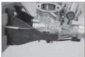
Fit the engine in the mounts and use a clamp to hold it in position. Adjust the engine so the face of the drive washer is 6 ^1/4 inches (159mm) forward of the firewall.
-
Use a pencil or felt-tipped pen to mark the locations for the engine mounting screws on the engine mount.
154.

natural_image
Close-up of a mechanical component with a tool inserted, no visible text or symbols155.

text_image
25/32 inch (20mm) 1½ inch (40mm)156.

natural_image
Close-up of a mechanical clamp or bracket component (no visible text or symbols)157.
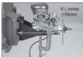
text_image
6½ inches (159mm)158.

natural_image
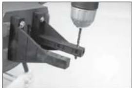
Close-up of a mechanical assembly with hoses and components (no visible text or symbols)- Remove the engine from the mounts. Use a drill and 5/32-inch (4mm) drill bit to drill the holes for the engine mounting screws.
→ TIP: Remove the mounts and use a drill press when drilling the holes in the engine mount to ensure the mounting screws are straight and the motor mounts easily.
-
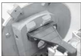
Fit the engine to the mounts. Slide an M4 washer on each of the M4 x 30 machine screws, then into the holes in the engine mounting lugs and into the mount.
-
Place an M4 washer on each screw, then a drop of threadlock on each screw. Use a 5.5mm nut driver and #2 Phillips screwdriver to install the M4 nuts that secure the engine to the engine mount.
-
Use a drill and 5/32-inch (4mm) drill bit to drill the hole for the throttle pushrod. Locate the hole near the mount and protrusion from the fi rewall.
-
Use a hobby knife with a #11 blade to remove the area in the sub-fl rewall to allow the lead for the spark plug to exit the fuselage.
159.
natural_image
Close-up of a mechanical tool with a drill bit inserted, no visible text or symbols160.

natural_image
Close-up of a mechanical engine component with visible gears and housing (no text or symbols)161.

natural_image
Mechanical assembly showing a metallic cylindrical component with bolts and mounting brackets (no visible text or symbols)162.
natural_image
Close-up of a mechanical device with a lever mechanism (no visible text or symbols)163.
natural_image
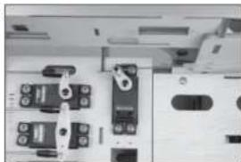
Close-up of a mechanical component with a circular housing and a lever mechanism (no visible text or symbols)- Remove the fuel tank fl oor from the fuselage by removing the four screws with a #1 Phillips screwdriver. Secure the ignition module in the fuselage. Use a hook and loop strap to ensure its location. Make any connections using the instructions provided with the engine.
→ The ignition module can also be located anywhere in the fuselage that it is convenient.
→ The ignition battery and/or the receiver battery can also be mounted in this location if necessary.
-
Replace the fuel tank floor and connect the leads between the engine and ignition module.
-
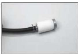
Mount the switch for the receiver and ignition module in the fuselage. The switches will be on opposite sides of the fuselage when installed. Secure a 3-inch (150mm) extension to the receiver switch using commercially available fastener (SPMA3054) to connect the switch to the receiver battery.
-
Use sandpaper to lightly sand the length of the throttle pushrod tube. Use a paper towel and isopropyl alcohol to remove any oils or debris from the tube.
-
Use medium CA to glue the tube in the fi rewall. Leave 1^3/_4 inch (19mm) of the tube exposed forward of the fi rewall.
→ Make sure the CA does not enter the tube, which could make the installation of the pushrod wire difficult.
natural_image
Interior view of a computer case with visible wiring and components (no text or symbols)
natural_image
Close-up of a mechanical device with internal components and mounting holes (no visible text or symbols)
natural_image
Close-up of a white electronic device with a black connector and ventilation slots (no visible text or symbols)
natural_image
A plain white cylindrical object on a neutral gray surface, no text or symbols visible.
natural_image
Close-up of a mechanical assembly with no visible text or symbols-
Slide the throttle pushrod into the pushrod tube. Connect the Z-bend in the throttle pushrod to the carburetor arm. It may be necessary to remove the engine for this step. Bend the pushrod slightly so it moves without binding.
-
Mount the throttle servo connector in the throttle servo arm so it is 7/16-inch (11m) from the center of the servo arm. Place a drop of canopy glue on the M2 nut, then install it on the underside of the arm to secure the connector.
→ It may be necessary to enlarge the hole in the servo arm so the connector can rotate freely.
-
Without the servo arm on the servo, switch on the radio system and center the throttle stick and trim. Install the servo arm on the servo parallel to the servo centerline.
-
Move the carburetor to the mid-throttle position and tighten the setscrew securing the pushrod to the connector at the servo.
-
Check the operation of the carburetor using the radio system. Move the throttle stick to full throttle.
natural_image
Close-up of a mechanical engine component with internal gears and shafts (no visible text or symbols)
text_image
7/16-inch (11mm)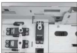
natural_image
Close-up of electronic components with no visible text or symbols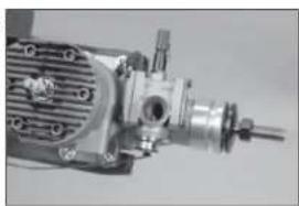
natural_image
Close-up of a mechanical assembly with gears and shafts (no visible text or symbols)
natural_image
Close-up of electronic components with no visible text or symbols-
Check that the carburetor opens fully. Adjust the settings in the radio if necessary to fully open the carburetor without binding the servo.
-
Check that the carburetor closes fully. Adjust the settings in the radio if necessary to fully close the carburetor without binding the servo.
-
Check that the throttle closes. Adjust the linkage as necessary.
Adjustments can also be made at the radio when using a computer radio. Make any large adjustment with the linkage and its position and fine-tune the operation of the carburetor using the radio features.
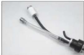
FUEL TANK INSTALLATION
-
Secure the tubing to the tube from the stopper using thin locking wire or a tie wrap. This will keep the tubing from sliding loose inside the tank. Use the clunk and tubing included with the engine.
-
Secure the tubing to the clunk using thin wire. This will keep the tubing from sliding loose inside the tank.
174.
natural_image
Close-up of a mechanical pump or motor assembly (no visible text or symbols)175.
natural_image
Close-up of electronic components including connectors and switches (no visible text or symbols)176.
natural_image
Close-up of a mechanical assembly with gears and shafts (no visible text or symbols)177.

natural_image
Close-up of a black electrical plug with a coiled cable (no text or symbols visible)178.
natural_image
Close-up of a white and black cable with metallic ends, isolated on plain background (no text or symbols)- Attach the clunk included with the kit to the stopper. Secure the tubing to the stopper and clunk.
→ This will be used for fueling and defueling.
→ Apply a very small amount of soapy water to the stopper to make it easier to install the stopper into the tank.
-
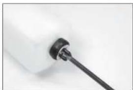
Insert the stopper fully into the tank. Check that the clunk can move freely in the tank. The tube to the clunk can be moved in or out to fl ne-tune the position of the clunk inside the tank. Once set, tighten the screw using a #1 Phillips screwdriver to secure the stopper in the tank.
-
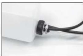
Secure a 5-inch (127mm) fuel line to the fi II line of the tank. The overflow line can be attached to the vent, as well as the remaining tubing to the clunk line that will eventually attach to the carburetor. Tie wraps can also be used to secure the fuel lines as well as wire ties.
-
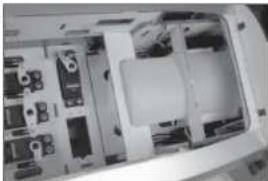
Secure the receiver and ignition batteries in the fuselage using hook and loop tape.
→ The batteries can also be mounted under the fuel tank tray.
- Slide the tubing from the tank through the hole in the fl rewall. The tank will fl t between the batteries. Foam rubber can be placed between the batteries and fuel tank to hold everything securely in the fuselage.
179.
natural_image
Close-up of a black and white electrical connector with wires (no visible text or symbols)180.
natural_image
Close-up of a white plastic bottle with a black screwdriver inserted (no text or symbols visible)181.
natural_image
Close-up of a white electronic device with black cable connectors (no visible text or symbols)182.

natural_image
Close-up of a mechanical device with visible wiring and components (no text or symbols)183.

natural_image
Interior view of a vehicle chassis showing internal components and wiring (no visible text or symbols)- Use medium CA to glue the fuel tank braces in the fuselage. Slide the fuel tank back against the rear brace once the CA fully cures.
→ The fuel tank can also be secured in the fuselage using hook and loop straps or tie-wraps.
COWLING INSTALLATION
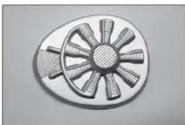
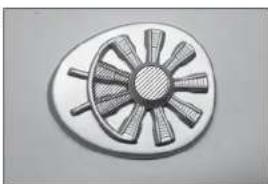
→ Trim the Radial Engine, EP ONLY.
- Trim the dummy radial engine as shown to allow cooling air to pass across the ESC. Remove the material in the center of the dummy radial for the propeller shaft and drive washer for your particular motor.
→ Trim the Radial Engine, GAS ONLY.
-
Trim the dummy radial engine to allow air to pass over the engine and to clear the carburetor. Remove the material in the center of the dummy radial for the propeller shaft and drive washer for your particular engine.
-
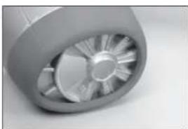
Use sandpaper to remove the paint from the dummy radial where it contacts the inside of the cowling. This will increase the bond of the adhesive to the dummy radial. Use 15-minute epoxy to glue the radial engine inside the cowling. Allow the epoxy to fully cure before proceeding.
-
Attach the cowling mounts to the fuselage using M3 x 10 socket head cap screws, M3 washers and M3 lock washers. Leave the mounts loose enough that they can be aligned with the cowling in the following steps.
→ Use care not to cross-thread the screws in the blind nuts when attaching the cowl mounts.
184.
natural_image
Interior view of a computer case showing internal components and connectors (no visible text or symbols)185.
natural_image
Illustration of a circular mechanical component with radial blades and a central hub (no text or symbols)186.
natural_image
Circular mechanical component with radial blades and central hub (no text or symbols)187.
natural_image
Close-up of a metallic turbine or impeller component with visible blades and central hub (no text or symbols)188.
natural_image
Close-up of a mechanical device with attached components and wiring (no visible text or symbols)-
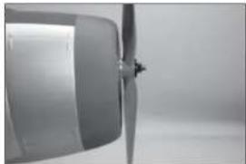
Slide the cowling into position. Attach the propeller to the motor shaft using the hardware included with the engine. Position the cowling so the propeller is equal distance from the cowling at the top and bottom.
-
Check the left right alignment of the cowling now as well.
-
Mark the location of the mounts on the inside of the cowling using a felt-tipped pen. Make sure the cowling does not move when making these marks. Note if the mounts fit fl at to the inside of the cowling.
→ The cowl mounts can also be tack glued to the cowl using medium CA. Be careful not to accidentally glue the mounts to the tabs, or get glue in the threads of the blind nuts.
- Remove the propeller and cowling. Use medium grit sandpaper to sand the mounts to make sure they fit tightly against the cowling.
→ If the mounts do not fit tightly they may come loose after they are glued to the cowling.
- Sand the area inside the cowling where the mounts rest. Use a paper towel and isopropyl alcohol to remove any oils or debris from the inside of the cowling.
→ Preparation for gluing the mounts is important to guarantee the adhesive can properly bond the mounts to the inside of the cowling.
189.
natural_image
Close-up of a propeller blade and fan blade (no text or symbols visible)190.

natural_image
Close-up of a metallic propeller or fan blade with a central hub (no visible text or symbols)191.

natural_image
Close-up of a white cylindrical mechanical component with a black metal rod inserted, no visible text or symbols.192.
natural_image
Close-up of a hand holding a small electronic component, with wiring and circuit board in background (no visible text or symbols)193.
natural_image
Close-up of a hand holding a white sheet of paper on a plain surface (no text or symbols visible)- Apply a coat of 15-minute epoxy to the mounts where the fit to the cowling.
Do not apply too much glue and be very careful not to glue the cowling mounts to the mounts already fitted to the fuselage.
→ Using a thickening agent in the epoxy, such as micro balloons or colloidal silica, can help prevent the epoxy from running.
- Apply epoxy to the cowling in the mount locations. Fit the cowling to the fuselage and align as instructed earlier. Allow the epoxy to fully cure before proceeding.
Once the epoxy has cured, remove the cowling from the fuselage. Apply a fillet of epoxy between the mount and cowl to strengthen the joint between the cowl and mounts.
196. Attach the fuel lines and muffler. Make sure to secure all the connections to the engine so they don't vibrate cause interference with the engine during flight.
197. Trim the cowl as necessary to provide access to any carburetor adjustments. Use a fuel fler and "T" flting to allow fueling of the model without removing the cowling. Cut the bottom of the cowling to allow for the exhaust pipes to exit.
☐ SCALE ACCESSORY INSTALLATION
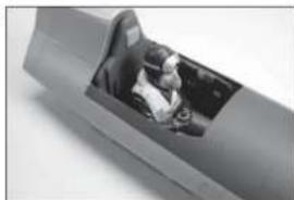
- Glue the pilot into the pilot seat using a silicone adhesive or contact adhesive. Allow the adhesive to fully cure before proceeding.
194.

natural_image
Person operating a robotic arm with sensors and wiring (no visible text or symbols)195.

natural_image
Close-up of a gloved hand holding a small object with a black mark, against a plain white background (no text or symbols visible)196.

natural_image
Close-up of a mechanical assembly with gears and shafts (no visible text or symbols)197.

natural_image
Close-up of a mechanical component with a metallic knob and circular base (no visible text or symbols)198.
natural_image
Close-up of a person inside a car seat, viewed from the side (no visible text or symbols)- Lightly sand the inside edge of the canopy using medium grit sandpaper. Remove any oils or debris with a paper towel and isopropyl alcohol.
- Use canopy glue or contact adhesive to attach the canopy to the cockpit hatch. Use low-tack tape to hold the canopy in position until the adhesive fully cures.
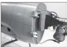
→ Placing wooden sticks between the tape and canopy will hold the canopy tightly against the hatch until the adhesive has cured. - Remove the covering on the top of the fuselage for the antenna. Thread the antenna into the pre-installed nut in the fuselage.
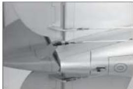
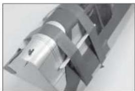
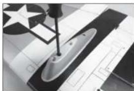
→ Remove the antenna for transport to avoid damage to it or the fuselage. - Lightly sand the intakes where they fit against the fuselage. Use canopy glue or contact adhesive to glue the intakes to the fuselage. Use the printing on the covering to locate their correct position. Use low-tack tape to hold them secure until the adhesive fully cures.
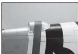
- Lightly sand the exhaust where it fi ts against the fuselage. Use canopy glue or contact adhesive to glue the exhaust to the fuselage. Use the printing on the covering to locate the correct position. Use low-tack tape to hold it secure until the adhesive fully cures.
199.
natural_image
Close-up of a hand using a tool to cut a metal grid structure (no text or symbols visible)200.
natural_image
Close-up of a metallic mechanical component with interlocking parts (no visible text or symbols)201.

natural_image
Close-up of a white aircraft fuselage with a star emblem, against a plain sky background (no text or symbols visible)202.

natural_image
Close-up of a medical imaging device with a transparent lens and screen (no visible text or symbols)203.
natural_image
Close-up of a camera lens and optical fiber assembly (no visible text or symbols)-
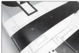
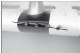
Remove the covering on the bottom of the wing for the bomb mounts.
-
Attach the bomb mounts to the bottom of the wing using two M2.6 x 10 machine screws and two M2.6 washers. Thread the screws into the pre-installed nuts in the wing. Use a #2 Phillips screwdriver to tighten the screws.
-
Attach the bombs to the bomb mounts using two M3 x 10 machine screws and two M3 washers. Use a #2 Phillips screwdriver to tighten the screws.
→ Remove the bombs for transport to avoid damage to them.
-
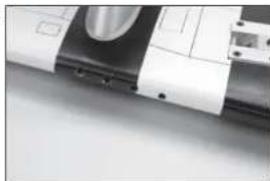
Use a hobby knife to remove the covering from the leading edge of the wing for the gun mounts.
-
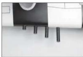
Insert the rounded ends of the guns into the holes in the loading edge of the wing. The depth of each gun is determined by the structure installed inside the wing. Check to make sure each gun is parallel as shown.
204.
natural_image
Close-up of a mechanical component with black and white bands (no visible text or symbols)205.
natural_image
Close-up of a mechanical component with a hammer and screwdriver, featuring star patterns on a grid background (no visible text or symbols)206.

natural_image
Black-and-white photo of a missile on display with a star emblem in the background (no visible text or symbols)207.
natural_image
Close-up of a mechanical component with metallic parts and mounting holes (no visible text or symbols)208.
natural_image
Interior view of a minimalist room with dark cylindrical objects and a circular object on the wall (no visible text or symbols)- Check that the guns are aligned as shown in the photo. If there are any alignment issues, use a 15/64-inch (6mm) drill bit to carefully alter the holes. Once aligned, use 15-minute epoxy to glue the guns into position.
→ Small adjustments can be made by moving them slightly. If larger adjustments are necessary, the holes may require enlargement carefully using a drill bit.
209.
natural_image
Close-up of a mechanical component with a metallic shaft and cylindrical head (no visible text or symbols)□ CENTER OF GRAVITY
An important part of preparing the aircraft for flight is properly balancing the model.
- Attach the wing panels to the fuselage. Make sure to connect the leads from the aileron, flap and retract to the appropriate leads from the receiver. Make sure the leads are not exposed outside the fuselage before tightening the wing bolts. Your model should be flight-ready before balancing.
- The recommended Center of Gravity (CG) location for your model is 4–4 12 inches (102–114mm) behind the leading edge of the wing.
- When balancing your model, make sure it is assembled and ready for flight. Support the plane inverted at the marks made on the wing with your fingers or a commercially available balancing stand.
→ It may be necessary to add weight to the nose of your model to achieve the correct Center of Gravity, or to adjust the flight handling to suit your flying style.
CAUTION: You must adjust your aircraft's center of gravity and balance your model properly before attempting flights.

text_image
4-4½ inches (102-114mm)CONTROL THROWS
- Turn on the transmitter and receiver of your model. Check the movement of the rudder using the transmitter. When the stick is moved to the right, the rudder should also move right. Reverse the direction of the servo at the transmitter if necessary.
- Check the movement of the elevator with the radio system. Moving the elevator stick toward the bottom of the transmitter will make the airplane elevator move up.
- Check the movement of the ailerons with the radio system. Moving the aileron stick to the right will make the right aileron move up and the left aileron move down.
- Use a throw meter to adjust the throw of the elevator, allerons and rudder. Set the high rates first, then use the rate functions to set the remaining rates.
Aileron:
High Rate Low Rate
Up: 19/32 inches (15mm) 11/32 inches (9mm)
Down: 15/32 inches (12mm) 9/32 inches (7mm)
Elevator:
High Rate Low Rate
Up: 25/32 inches (20mm) 15/32 inches (12mm)
Down: 25/32 inches (20mm) 15/32 inches (12mm)
Rudder:
High Rate Low Rate
Right: 1^3/_16 inches (30mm) 19/32 inches (15mm)
Left: 1^3/_16 inches (30mm) 19/32 inches (15mm)
Flaps:
19/32–25/32 inches (15–20mm)
Landing 1^3/4-2^5/32 inches (45–55mm)
These are general guidelines measured from our own flight tests. You can experiment with different rates to match your preferred style of flying.
Travel Adjust and Sub-Trims are not listed and should be adjusted according to each individual model and preference. Always install the control horns 90 degrees to the servo center line. Use sub-trim as a last resort to center the servos.
We highly recommend re-binding the radio system once all of the control throws are set. This will keep the servos from moving to their endpoints until the transmitter and receiver connect.
□ PREFLIGHT CHECKLIST
- Charge the transmitter, receiver and motor battery for your airplane. Use the recommended charger supplied with your radio system. Follow the instructions provided with the radio. Charge the radio system the night before each flying session. Charge the transmitter and receiver batteries using only included or manufacturer-recommended chargers. Follow all manufacturer's instructions for your electronic components.
- Check the radio installation and make sure all control surfaces (aileron, elevator, rudder and throttle) move correctly (i.e., the correct direction and with the recommended throws).
- Check all the hardware (control horns, servo horns, and clevises) to make sure they are secure and in good condition.
- Prior to each 11 ying session (and especially with a new model), perform a range check of your radio system. See your radio manual for the recommended range and instructions for your particular radio system.
- Run the motor. With the model securely anchored, repeat the range check procedure. The range should not be signifi cantly affected. If it is, do not attempt to fly! Remove the radio equipment and have it inspected by the manufacturer.
DAILY FLIGHT CHECKS
- Check the battery voltage of the transmitter battery. Do not fly below the manufacturer's recommended voltage. To do so can crash your aircraft.
When you check these batteries, ensure you have the polarities correct on your expanded scale voltmeter.
- Check all hardware (linkages, screws, nuts, and bolts) prior to each day's fl light. Ensure that binding does not occur and that all parts are properly secured.
- Ensure all surfaces are moving in the proper manner.
- Perform a ground range check before each day's fl ying session.
- Prior to starting your aircraft, turn off your transmitter, then turn it back on. Do this each time you start your aircraft. If any critical switches are on without your knowledge, the transmitter alarm will sound a warning.
- Check that all trim levers are in the proper location.
- All servo pigtails and switch harness plugs should be secured in the receiver. Make sure the switch harness moves freely in both directions.
□ LIMITED WARRANTY
What this Warranty Covers
Horizon Hobby, LLC, (Horizon) warrants to the original purchaser that the product purchased (the "Product") will be free from defects in materials and workmanship at the date of purchase.
What Is Not Covered
This warranty is not transferable and does not cover (i) cosmetic damage, (ii) damage due to acts of God, accident, misuse, abuse, negligence, commercial use, or due to improper use, installation, operation or maintenance, (iii) modification of or to any part of the Product, (iv) attempted service by anyone other than a Horizon Hobby authorized service center, (v) Product not purchased from an authorized Horizon dealer, (vi) Product not compliant with applicable technical regulations, or (vii) use that violates any applicable laws, rules, or regulations.
OTHER THAN THE EXPRESS WARRANTY ABOVE, HORIZON MAKES NO OTHER WARRANTY OR REPRESENTATION, AND HEREBY DISCLAIMS ANY AND ALL IMPLIED WARRANTIES, INCLUDING, WITHOUT LIMITATION, THE IMPLIED WARRANTIES OF NON-INFRINGEMENT, MERCHANTABILITY AND FITNESS FOR A PARTICULAR PURPOSE. THE PURCHASER ACKNOWLEDGES THAT THEY ALONE HAVE DETERMINED THAT THE PRODUCT WILL SUITABLY MEET THE REQUIREMENTS OF THE PURCHASER'S INTENDED USE.
Purchaser's Remedy
Horizon's sole obligation and purchaser's sole and exclusive remedy shall be that Horizon will, at its option, either (i) service, or (ii) replace, any Product determined by Horizon to be defective. Horizon reserves the right to inspect any and all Product(s) involved in a warranty claim. Service or replacement decisions are at the sole discretion of Horizon. Proof of purchase is required for all warranty claims. SERVICE OR REPLACEMENT AS PROVIDED UNDER THIS WARRANTY IS THE PURCHASER'S SOLE AND EXCLUSIVE REMEDY.
Limitation of Liability
HORIZON SHALL NOT BE LIABLE FOR SPECIAL, INDIRECT, INCIDENTAL OR CONSEQUENTIAL DAMAGES, LOSS OF PROFITS OR PRODUCTION OR COMMERCIAL LOSS IN ANY WAY, REGARDLESS OF WHETHER SUCH CLAIM IS BASED IN CONTRACT, WARRANTY, TORT, NEGLIGENCE, STRICT LIABILITY OR ANY OTHER THEORY OF LIABILITY, EVEN IF HORIZON HAS BEEN ADVISED OF THE POSSIBILITY OF SUCH DAMAGES. Further, In no event shall the liability of Horizon exceed the individual price of the Product on which liability is asserted. As Horizon has no control over use, setup, finl assembly, modification or misuse, no liability shall be assumed nor accepted for any resulting damage or injury. By the act of use, setup or assembly, the user accepts all resulting liability. If you as the purchaser or user are not prepared to accept the liability associated with the use of the Product, purchaser is advised to return the Product immediately in new and unused condition to the place of purchase.
Law
These terms are governed by Illinois law (without regard to conflict of law principals). This warranty gives you specific legal rights, and you may also have other rights which vary from state to state. Horizon reserves the right to change or modify this warranty at any time without notice.
WARRANTY SERVICES
Questions, Assistance, and Services
Your local hobby store and/or place of purchase cannot provide warranty support or service. Once assembly, setup or use of the Product has been started, you must contact your local distributor or Horizon directly. This will enable Horizon to better answer your questions and service you in the event that you may need any assistance. For questions or assistance, please visit our website at www.horizonhobby.com, submit a Product Support Inquiry, or call the toll free telephone number referenced in the Warranty and Service Contact Information section to speak with a Product Support representative.
Inspection or Services
If this Product needs to be inspected or serviced and is compliant in the country you live and use the Product in, please use the Horizon Online Service Request submission process found on our website or call Horizon to obtain a Return Merchandise Authorization (RMA) number. Pack the Product securely using a shipping carton. Please note that original boxes may be included, but are not designed to withstand the rigors of shipping without additional protection. Ship via a carrier that provides tracking and insurance for lost or damaged parcels, as Horizon is not responsible for merchandise until it arrives and is accepted at our facility. An Online Service Request is available at http://www.horizonhobby.com/content/_service-centerRender-service-center. If you do not have internet access, please contact Horizon Product Support to obtain a RMA number along with instructions for submitting your product for service. When calling Horizon, you will be asked to provide your complete name, street address, email address and phone number where you can be reached during business hours. When sending product into Horizon, please include your RMA number, a list of the Included items, and a brief summary of the problem. A copy of your original sales receipt must be included for warranty consideration. Be sure your name, address, and RMA number are clearly written on the outside of the shipping carton.
NOTICE: Do not ship LiPo batteries to Horizon. If you have any issue with a LiPo battery, please contact the appropriate Horizon Product Support office.
Warranty Requirements
For Warranty consideration, you must include your original sales receipt verifying the proof-of-purchase date. Provided warranty conditions have been met, your Product will be serviced or replaced free of charge. Service or replacement decisions are at the sole discretion of Horizon.
Non-Warranty Service
Should your service not be covered by warranty, service will be completed and payment will be required without notification or estimate of the expense unless the expense exceeds 50% of the retail purchase cost. By submitting the item for service you are agreeing to payment of the service without notification. Service estimates are available upon request. You must include this request with your item submitted for service. Non-warranty service estimates will be billed a minimum of 12 hour of labor. In addition you will be billed for return freight. Horizon accepts money orders and cashier's checks, as well as Visa, MasterCard, American Express, and Discover cards. By submitting any item to Horizon for service, you are agreeing to Horizon's Terms and Conditions found on our website http://www.horizonhobby.com/content/_service-center_render-service-center.
ATTENTION: Horizon service is limited to Product compliant in the country of use and ownership. If received, a non-compliant Product will not be serviced. Further, the sender will be responsible for arranging return shipment of the un-serviced Product, through a carrier of the sender's choice and at the sender's expense. Horizon will hold non-compliant Product for a period of 60 days from notification, after which it will be discarded.
☐ WARRANTY AND SERVICE CONTACT INFORMATION
| Country of Purchase | Horizon Hobby Contact Information Address | ||
| United States of America | Horizon Service Center (Repairs and Repair Requests) | servicecenter.horizonhobby.com/RequestForm/ | 4105 Fieldstone RdChampaign, Illinois, 61822 USA |
| Horizon Product Support (Product Technical Assistance) | productsupport@horizonhobby.com.877-504-0233 | ||
| Sales | websales@horizonhobby.com | ||
| 800-338-4639 | |||
| EU | Horizon Technischer Service service@horizonhobby.euSales: Horizon Hobby GmbH +49 (0) 4121 2655 100 | Hanskampring 9D 22885 Barsbüttel, Germany | |

☐ INSTRUCTIONS FOR DISPOSAL OF WEEE BY USERS IN THE EUROPEAN UNION

This product must not be disposed of with other waste. Instead, it is the user's responsibility to dispose of their waste equipment by handing it over to a designated collections point for the recycling of waste electrical and electronic equipment. The separate collection and recycling of your waste equipment at the time of disposal will help to conserve natural resources and ensure that it is recycled in a manner that protects human health and the environment. For more information about where you can drop off your waste equipment for recycling, please contact your local city offi ce, your household waste disposal service or where you purchased the product.
INSTALLATION DER KLAPPE
natural_image
Close-up of a white plastic sheet with a gray adhesive clip attached (no text or symbols visible)2.

natural_image
Simple line drawing of a fish-like shape with an arrow pointing to its body (no text or symbols)3.
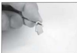
natural_image
Close-up of a hand holding a small metallic clip against a plain background (no text or symbols visible)4.
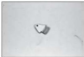
natural_image
Simple geometric shape resembling a pin or block on a plain background (no text or symbols)5.
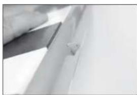
natural_image
Close-up of a metallic tool interacting with a surface, possibly a cutting or cleaning tool (no visible text or symbols)natural_image
Close-up of a metallic rectangular object with a black horizontal line and white top section, no visible text or symbols.7.
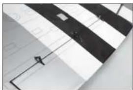
natural_image
Close-up of a striped fabric with a small square mark, mounted on a metal frame (no text or symbols visible)8.
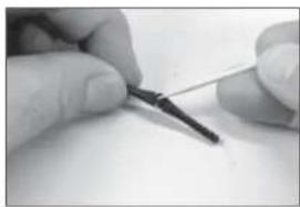
natural_image
Close-up of hands holding a small tool with a dark tip, no visible text or symbols9.
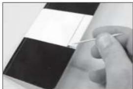
natural_image
Close-up of a hand holding a small object against a dark and white striped surface (no text or symbols visible)natural_image
Close-up of hands holding a pen, no visible text or symbols11.

natural_image
Close-up of a hand holding a small wire with a pen, next to a dark rectangular object (no visible text or symbols)12.

natural_image
Close-up of a hand holding a small white object over a flat surface, possibly part of a device or tool (no visible text or symbols)13.
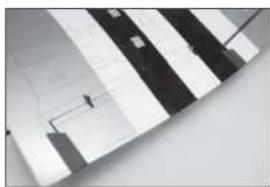
natural_image
Close-up of a striped patterned surface with no visible text or symbols14.
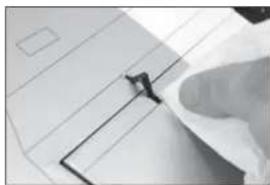
natural_image
Close-up of a hand holding a small object over a document (no visible text or symbols)□ MONTAGE DES QUERRUDERS
natural_image
Close-up of a metallic object with a star symbol on its surface (no text or symbols visible)16.
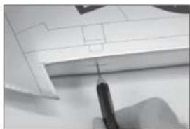
natural_image
Close-up of a hand holding a pen, partially visible through a white architectural or mechanical component (no text or symbols)17.
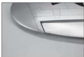
natural_image
Close-up of a metallic curved object with grid pattern, possibly a tool or component (no visible text or symbols)18.
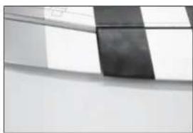
natural_image
Abstract grayscale geometric pattern with diagonal stripes and a central dark band (no text or symbols)19.
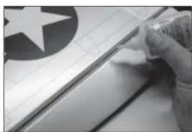
natural_image
Close-up of a hand holding a small object over a grid-patterned surface, with no visible text or symbols.natural_image
Close-up of hands holding a document with a star emblem and grid paper (no visible text or symbols)
natural_image
Close-up of a hand holding a pen, with a large symbol on the left (no readable text or symbols)
natural_image
Close-up of a hand holding a small object, possibly a tool or device, with no visible text or symbols.
natural_image
Close-up of a mechanical component with a circular inset showing a magnified view (no visible text or symbols)
text_image
15/16 inch (24mm)natural_image
Close-up of hands holding a small object with a thin rod (no visible text or symbols)
natural_image
Close-up of a hand holding a small object with a tool, possibly a component or tool, against a plain background (no visible text or symbols)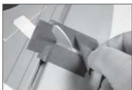
natural_image
Close-up of a hand using a tool to cut or mark a small object, no visible text or symbols
natural_image
Close-up of a hand holding a black and white electronic device (no visible text or symbols)
natural_image
Close-up of a sewing machine needle stitching a star-patterned sheet (no text or symbols visible)natural_image
Close-up of a sewing machine needle stitching a metal sheet (no text or symbols visible)41.

natural_image
Close-up of a hand using a pen to write on a chart with a line graph in the background (no visible text or symbols)42.

natural_image
Simple electrical component with a bent wire and terminal block (no text or symbols visible)43.

natural_image
Abstract geometric shapes with angular and linear markings (no text or symbols)44.
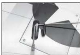
natural_image
Close-up of a metallic mechanical component with curved blades and mounting base (no visible text or symbols)natural_image
Close-up of a mechanical fan or propeller with blades and blades, no visible text or symbols46.
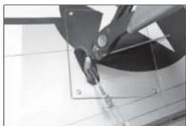
natural_image
Close-up of a mechanical component with a circular base and triangular blades, no visible text or symbols47.

natural_image
Close-up of a mechanical component with a star-like symbol and a triangular base (no visible text or symbols)48.
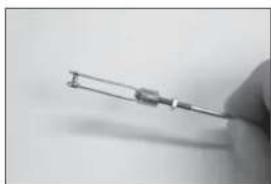
natural_image
Close-up of a hand holding a small metallic tool or wire (no visible text or symbols)natural_image
Close-up of a metal bracket with clamps and mounting holes (no text or symbols visible)50.
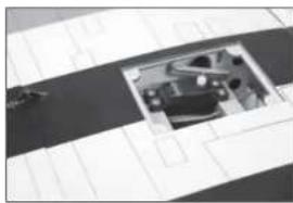
natural_image
Abstract geometric pattern with curved lines and a central framed picture (no text or symbols)51.
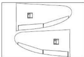
natural_image
Pure geometric diagram with curved and straight lines, no text or symbols present52.
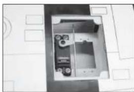
natural_image
Interior view of a room with furniture and fixtures (no visible text or symbols)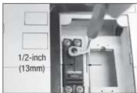
text_image
1/2-inch (13mm)natural_image
Close-up of a metallic mechanical component with a small protrusion and a diagonal line (no visible text or symbols)54.
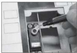
natural_image
Close-up of a hand using a tool to adjust or install electronic components (no visible text or symbols)55.
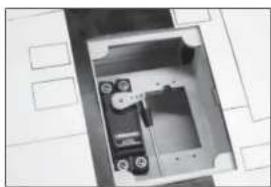
natural_image
Interior view of a room with furniture and doorways (no visible text or symbols)56.
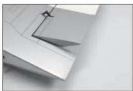
natural_image
Close-up of a white mechanical component with a metal bracket and angled edge (no visible text or symbols)57.
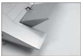
natural_image
Close-up of a metallic architectural element with angled surfaces and a small bracket (no text or symbols visible)natural_image
Close-up of a metallic mechanical component with a small protrusion and a diagonal line (no visible text or symbols)59.
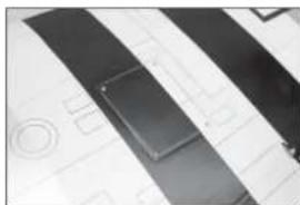
natural_image
Abstract geometric shapes with diagonal stripes and a central rectangular element (no text or symbols)60.
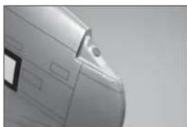
natural_image
Close-up of a metallic mechanical component with mounting holes and a small inset view (no text or symbols visible)61.
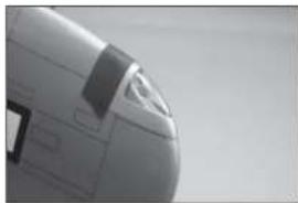
natural_image
Close-up of a jet aircraft's side profile showing nose, fuselage, and fuselage (no visible text or symbols)62.
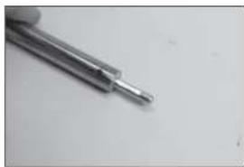
natural_image
Close-up of a metallic tool tip with a pointed tip, resting on a plain surface (no text or symbols visible)natural_image
Metal mechanical tool with triangular tip and cylindrical body (no text or symbols visible)64.
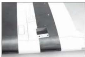
natural_image
Close-up of a metallic panel with white and black stripes, showing internal components (no text or symbols visible)65.
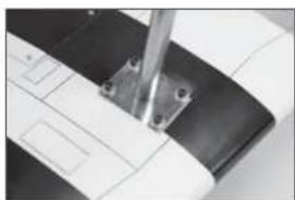
natural_image
Close-up of a mechanical component with a black and white curved surface, featuring a metal bracket and mounting holes (no visible text or symbols)66.
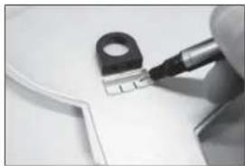
natural_image
Close-up of a hand using a power tool to cut a small electronic component (no visible text or symbols)67.
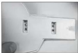
natural_image
Close-up of a white toilet or showerhead with two metallic buttons and a handle (no visible text or symbols)natural_image
Close-up of a metallic cylindrical object with black connectors, mounted on a wall (no visible text or symbols)69.
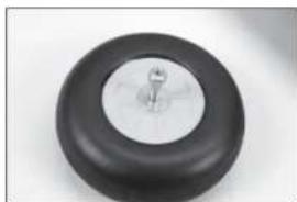
natural_image
Close-up of a black circular object with a metallic knob, possibly a knob or knob (no text or symbols visible)70.
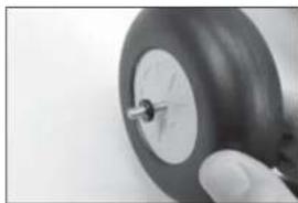
natural_image
Close-up of a hand holding a small black tire with a metallic screw (no visible text or symbols)71.
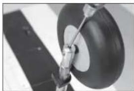
natural_image
Close-up of a mechanical component with a circular head and attached rod (no visible text or symbols)natural_image
Close-up of a mechanical component with no visible text or symbols73.
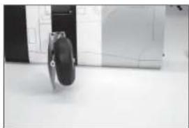
natural_image
Black and white photo of a dark, oval-shaped object on a light surface, with no visible text or symbols.74.
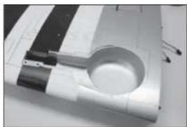
natural_image
Close-up of a white electronic device with a circular component and metallic components, possibly a lens or socket (no visible text or symbols)natural_image
Close-up of a white electronic component being inserted with a pen, no visible text or symbols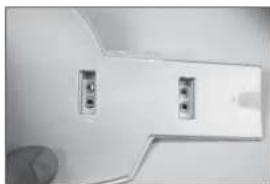
natural_image
Close-up of a white plastic door panel with two small buttons and a finger pointing to it (no text or symbols visible)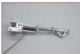
natural_image
Mechanical component with metallic shaft and attached rod, shown against plain background (no text or symbols visible)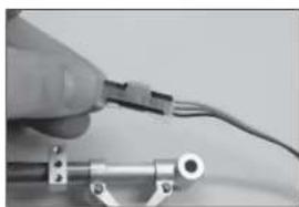
natural_image
Close-up of a hand holding a small electronic component with wires, no visible text or symbols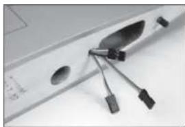
natural_image
Close-up of a computer monitor with a metallic clip and attached USB port (no visible text or symbols)natural_image
Close-up of a mechanical component with a spherical part and metallic shaft, set on a checkered floor (no visible text or symbols)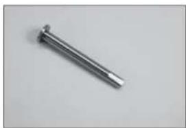
natural_image
Metal nail on a plain background (no text or symbols)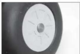
natural_image
Close-up of a black and white circular object with radial lines, resembling a wheel or tire (no text or symbols visible)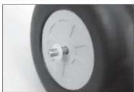
natural_image
Close-up of a car tire with a small metallic component inserted into the wheel (no visible text or symbols)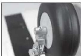
natural_image
Close-up of a mechanical component with a large tire and attached bracket (no visible text or symbols)natural_image
Close-up of a mechanical component with a circular dial and lever mechanism (no visible text or symbols)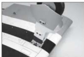
natural_image
Close-up of a sewing machine needle stitching fabric (no visible text or symbols)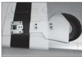
natural_image
Close-up of a mechanical component with black and white striped sections and a circular feature (no visible text or symbols)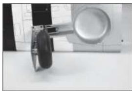
natural_image
Close-up of a mechanical device with a circular component mounted on a white surface (no visible text or symbols)
INSTALLATION VON STABILISATOR UND EITENRUDER
natural_image
Close-up of a hand holding a pen over a curved surface with grid lines (no text or symbols visible)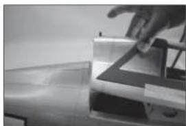
natural_image
Close-up of a hand interacting with a mechanical component (no visible text or symbols)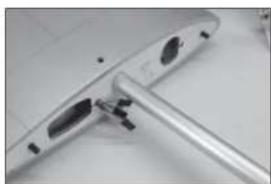
natural_image
Close-up of a metallic electronic device with a cylindrical port and mounting bracket (no visible text or symbols)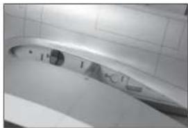
natural_image
Close-up of a metallic tool or component with a curved surface and a small inset view (no visible text or symbols)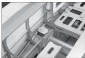
natural_image
Interior view of a modern office or retail space with furniture and display areas (no visible text or symbols)natural_image
Close-up of a metallic mechanical component with a curved edge detail (no visible text or symbols)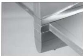
natural_image
Close-up of metallic structural beams or joints (no text or symbols visible)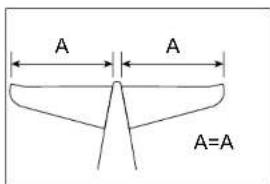
text_image
A A A=A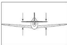
natural_image
Simple line drawing of an airplane with directional arrows indicating flight or movement (no text or symbols)
text_image
A A A=Anatural_image
Close-up of a hand holding a pen over a white surface, possibly part of a technical or architectural material (no visible text or symbols)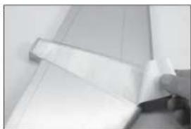
natural_image
Close-up of a hand holding a rolled-up sheet of paper or paper, with no visible text or symbols.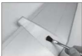
natural_image
Close-up of a hand holding a brush near a white rectangular object (no visible text or symbols)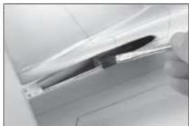
natural_image
Close-up of a car door handle with a knife inserted (no visible text or symbols)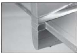
natural_image
Close-up of a metallic structural joint or bracket (no visible text or symbols)text_image
15/16 inch (24mm)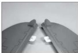
natural_image
Close-up of a mechanical component with two metallic clips and a small white component, no visible text or symbols.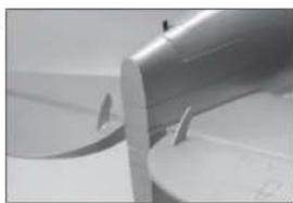
natural_image
Close-up of a metallic cylindrical component with a flanged edge and a circular base (no visible text or symbols)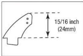
text_image
15/16 inch (24mm)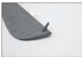
natural_image
Close-up of a gray plastic component with a small protrusion on the side (no visible text or symbols)natural_image
Close-up of a propeller blade with a metallic handle and mounting bracket (no visible text or symbols)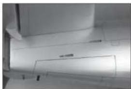
natural_image
Close-up of a mechanical component with no visible text or symbols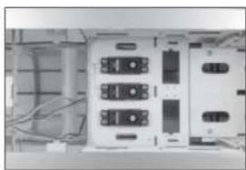
natural_image
Interior view of an electronic device showing a rack-mounted unit with multiple ports and cables (no visible text or labels)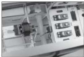
natural_image
Close-up of an electronic device with ports and wiring (no visible text or symbols)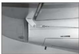
natural_image
Close-up of a curved mechanical or architectural component with no visible text or symbolsnatural_image
Close-up of a metallic aircraft wing with visible structural details and a circular emblem (no text or symbols)125.
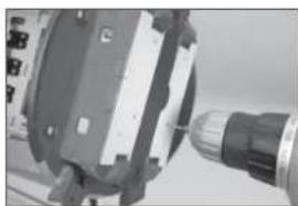
natural_image
Close-up of a mechanical component with a cylindrical shaft and housing (no visible text or symbols)126.
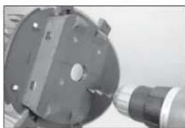
natural_image
Close-up of a mechanical component with a cylindrical housing and a threaded shaft (no visible text or symbols)127.
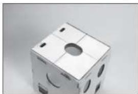
natural_image
Close-up of a white cube with circular cutouts and small holes, no visible text or symbolsnatural_image
Close-up of a hand holding a small object with abstract geometric shapes (no text or symbols visible)129.
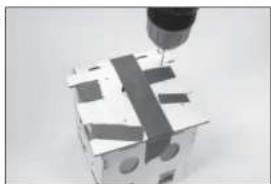
natural_image
Close-up of a mechanical component being cut with a tool, showing no visible text or symbols130.
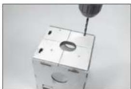
natural_image
Close-up of a precision screwdriver inserted into a small white mechanical component (no visible text or symbols)131.
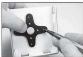
natural_image
Close-up of hands using a tool to adjust a black mechanical component (no visible text or symbols)132.
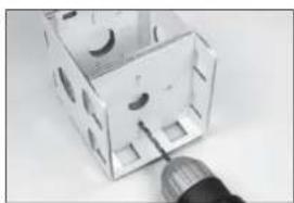
natural_image
Close-up of a small electronic component with circular cutouts and a metallic tip, no visible text or symbols.natural_image
Exterior view of a transparent plastic enclosure with internal compartments and bolt holes (no text or symbols visible)134.
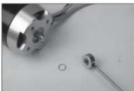
natural_image
Close-up of a metallic cylindrical component with a small circular hole and a separate cylindrical component (no text or symbols visible)135.
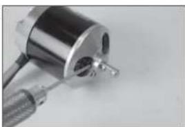
natural_image
Close-up of a metallic mechanical component with a cylindrical body and attached rod (no visible text or symbols)136.
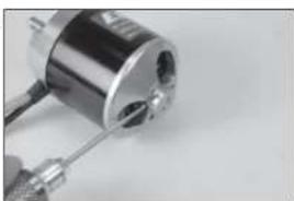
natural_image
Close-up of a metallic cylindrical mechanical component with a coiled spring and threaded end (no visible text or symbols)137.
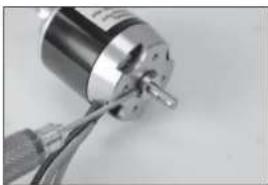
natural_image
Close-up of a metallic cylindrical electronic component with wires attached, no visible text or symbolsnatural_image
Close-up of a mechanical component with a metallic rod and attached housing (no visible text or symbols)139.
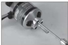
natural_image
Close-up of a mechanical component with a metallic shaft and threaded end (no visible text or symbols)140.
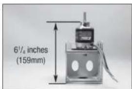
text_image
6½ inches (159mm)141.
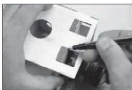
natural_image
Close-up of hands using a pen to apply a small electronic component (no visible text or symbols)142.
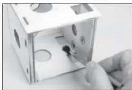
natural_image
Close-up of a hand inserting a small black object into a white box-like device (no visible text or symbols)natural_image
Exterior view of a white rectangular box with cutouts and circular holes (no text or symbols visible)144.
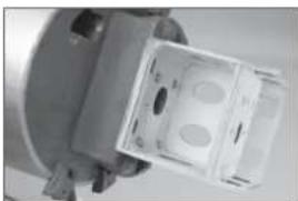
natural_image
Close-up of a mechanical component with two circular holes and a rectangular housing (no visible text or symbols)145.
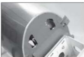
natural_image
Close-up of a metallic cylindrical component with two circular holes, partially stacked on a base (no visible text or symbols)146.
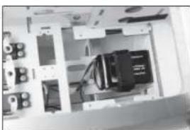
natural_image
Interior view of an electronic device with visible circuitry and components (no readable text or symbols)147.

natural_image
Close-up of a white electronic device with two ports and a black connector (no visible text or symbols)natural_image
Close-up of a black metal bracket mounted on a white base plate (no text or symbols visible)149.
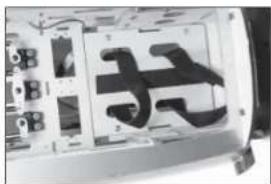
text_image
天150.
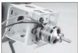
natural_image
Close-up of a mechanical device with a cylindrical component and wires, no visible text or symbols151.
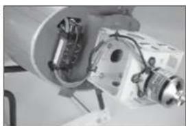
natural_image
Close-up of a mechanical assembly with internal components and wiring (no visible text or symbols)152.
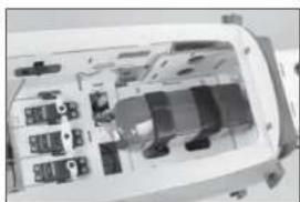
natural_image
Interior view of a device casing showing internal components and wiring (no visible text or symbols)natural_image
Close-up of a mechanical component with a cylindrical tool inserted, no visible text or symbols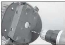
natural_image
Close-up of a mechanical component with a cylindrical housing and a threaded shaft (no visible text or symbols)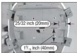
text_image
25/32 inch (20mm) 1½ inch (40mm)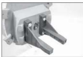
natural_image
Close-up of a mechanical clamp or bracket component (no visible text or symbols)text_image
6½ inches (159mm)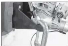
natural_image
Close-up of a mechanical assembly with hoses and components (no visible text or symbols)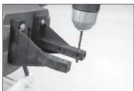
natural_image
Close-up of a precision tool tip with a drill bit (no visible text or symbols)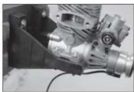
natural_image
Close-up of a mechanical assembly with metallic components and wiring (no visible text or symbols)
natural_image
Mechanical assembly with metallic components and bolts (no visible text or symbols)natural_image
Close-up of a mechanical device with a lever and handle (no visible text or symbols)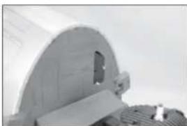
natural_image
Close-up of a metallic mechanical component with a circular top and internal cutout (no visible text or symbols)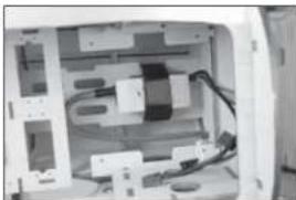
natural_image
Interior view of a computer room showing internal components and wiring (no visible text or symbols)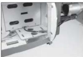
natural_image
Close-up of a mechanical component with mounting holes and a cylindrical housing (no visible text or symbols)natural_image
Close-up of a white electronic device with a black connector and ventilation slots (no visible text or symbols)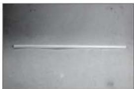
natural_image
A plain white cylindrical object on a plain gray surface, no text or symbols visible.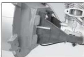
natural_image
Close-up of a mechanical component with no visible text or symbols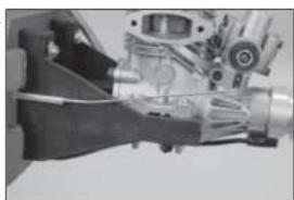
natural_image
Close-up of a mechanical assembly with gears and a lever mechanism (no visible text or symbols)
text_image
7/16-inch (11mm)natural_image
Close-up of electronic components including connectors and switches (no visible text or symbols)172.
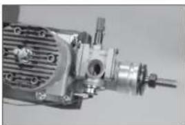
natural_image
Close-up of a mechanical assembly with gears and shafts (no visible text or symbols)173.
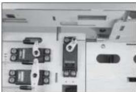
natural_image
Close-up of a mechanical or electronic component with multiple ports and connectors (no visible text or symbols)174.
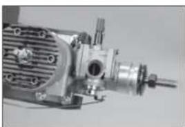
natural_image
Close-up of a mechanical pump or motor assembly (no visible text or symbols)175.
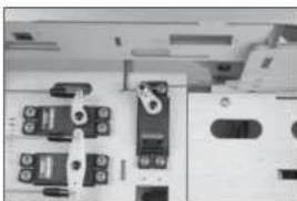
natural_image
Close-up of a mechanical or electronic component with multiple connectors and mounting holes (no visible text or symbols)natural_image
Close-up of a mechanical device with cooling fan and shaft (no visible text or symbols)177.
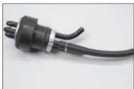
natural_image
Close-up of a black electrical plug with a coiled cable (no text or symbols visible)178.
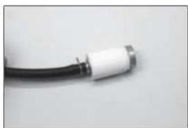
natural_image
Close-up of a black cable with white connector (no text or symbols visible)179.
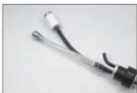
natural_image
Close-up of a black and white electronic device with wires and connectors (no visible text or symbols)180.

natural_image
Close-up of a white plastic bottle with a black screwdriver inserted (no text or symbols visible)natural_image
Close-up of a white electronic device with black connectors and wires (no visible text or symbols)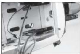
natural_image
Interior view of a device showing internal components and wiring (no visible text or symbols)
natural_image
Interior view of a vehicle chassis showing internal components and wiring (no visible text or symbols)
natural_image
Interior view of a computer case showing internal components and casing (no visible text or labels)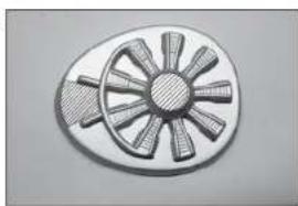
natural_image
Illustration of a fan-shaped mechanical component with radial blades and central hub (no text or symbols)natural_image
Illustration of a circular fan with radial blades, no text or symbols present
natural_image
Close-up of a mechanical component with radial blades and central hub (no visible text or symbols)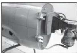
natural_image
Close-up of a mechanical device with attached components and wiring (no visible text or symbols)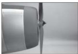
natural_image
Close-up of a metallic propeller or fan blade against a plain background (no text or symbols visible)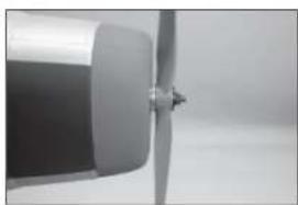
natural_image
Close-up of a metallic propeller or fan blade with a central hub (no visible text or symbols)natural_image
Close-up of a hand holding a tool interacting with a white cylindrical object (no visible text or symbols)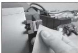
natural_image
Close-up of a hand inserting a small electronic component into a circuit board (no visible text or symbols)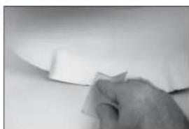
natural_image
Close-up of a hand holding a piece of paper on a plain surface (no text or symbols visible)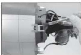
natural_image
Close-up of a robotic arm gripping a mechanical component (no visible text or symbols)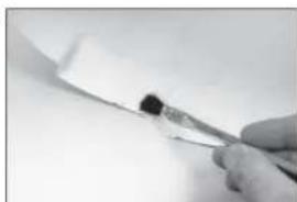
natural_image
Close-up of a gloved hand holding a pen with a black ink mark, against a plain white background (no text or symbols visible)natural_image
Close-up of a mechanical assembly with gears and shafts (no visible text or symbols)
natural_image
Close-up of a mechanical component with a central shaft and circular base (no visible text or symbols)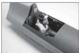
natural_image
Close-up of a mechanical component with a visible internal opening (no text or symbols)
natural_image
Close-up of a hand holding a metal tray with grid pattern (no visible text or symbols)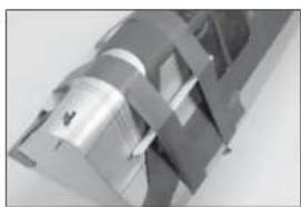
natural_image
Close-up of a metallic mechanical component with interlocking brackets (no visible text or symbols)natural_image
Close-up of a jet aircraft wing with visible propellers and nose cone (no text or symbols)202.
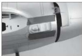
natural_image
Close-up of a medical imaging device with no visible text or symbols203.

natural_image
Close-up of a mechanical component with black and white bands (no visible text or symbols)204.
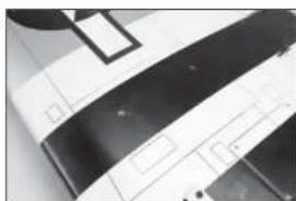
natural_image
Close-up of a white electronic device with black insulation bands and control panel (no visible text or symbols)205.
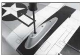
natural_image
Close-up of a sewing machine needle stitching fabric with star-patterned fabric (no visible text or symbols)natural_image
Black-and-white photo of a missile on display with a flag and star emblem in the background (no visible text or symbols)207.
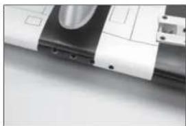
natural_image
Close-up of a mechanical component with a metallic blade and mounting holes (no visible text or symbols)208.
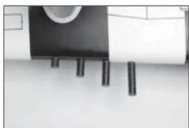
natural_image
Close-up of a black-and-white photo of a wall-mounted cylindrical object with three vertical rods, no visible text or symbols.209.
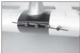
natural_image
Close-up of a mechanical component with a cylindrical shaft and flange, no visible text or symbolsDER SCHWERPUNKT
text_image
4-4½ inches (102-114mm)□ RUDERAUSSCHLAG
INSTALLATION DES VOLETS
natural_image
Close-up of a white plastic object with a gray rectangular indentation on the side (no visible text or symbols)2.

natural_image
Simple line drawing of a fish-like shape with an arrow pointing to its body (no text or symbols)3.

natural_image
Close-up of a hand holding a small white object with a thin black line, against a plain background (no text or symbols visible)4.

natural_image
Simple sketch of a small object on a plain surface (no text or symbols)5.

natural_image
Close-up of a hand holding a flat blade over a surface, with no visible text or symbolsnatural_image
Close-up of a metallic rectangular object with a black horizontal line, no visible text or symbols7.

natural_image
Close-up of a striped fabric or fabric with a small black-and-white object attached (no visible text or symbols)8.

natural_image
Close-up of hands holding a pen tip, no visible text or symbols9.
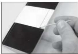
natural_image
Close-up of a hand holding a pen over a small object on a dark surface (no visible text or symbols)natural_image
Close-up of hands holding a small tool, no visible text or symbols11.

natural_image
Close-up of a gloved hand holding a small tool, with a dark rectangular object in the background (no visible text or symbols)12.

natural_image
Close-up of a hand holding a small white object over a metallic surface (no visible text or symbols)13.

natural_image
Abstract geometric pattern with diagonal striped and rectangular shapes (no text or symbols)14.
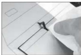
natural_image
Close-up of a hand holding a small object over a document or paper (no visible text or symbols)INSTALLATION DE L'AILERON
natural_image
Close-up of a metallic object with a star symbol and curved edge, no visible text or markings16.

natural_image
Close-up of a hand holding a small object over a white architectural or mechanical component (no visible text or symbols)17.
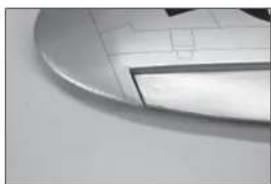
natural_image
Close-up of a computer mouse with a curved handle and grid pattern (no visible text or symbols)18.

natural_image
Abstract grayscale geometric pattern with diagonal stripes and a dark central band (no text or symbols)19.

natural_image
Close-up of a hand holding a pen over a grid of paper with a star symbol in the background (no readable text or symbols)natural_image
Close-up of hands holding a document with a star emblem (no visible text or symbols)
natural_image
Close-up of a hand holding a pen, with a large symbol on the wall (no readable text or symbols)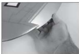
natural_image
Close-up of a hand holding a small object, possibly a tool or device, with no visible text or symbols.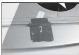
natural_image
Close-up of a mechanical component with a circular head and rectangular base (no visible text or symbols)
text_image
15/16 inch (24mm)natural_image
Close-up of hands holding a small object with a tool, possibly a tool or component (no visible text or symbols)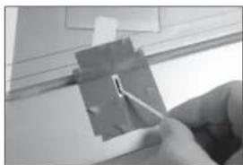
natural_image
Close-up of a hand using a tool to cut or mark a small component on a light surface (no visible text or symbols)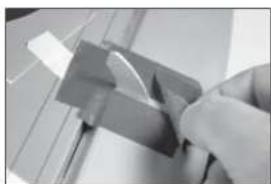
natural_image
Close-up of a hand using a tool to cut or apply a metallic component (no visible text or symbols)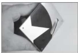
natural_image
Hand holding a compact electronic device with a curved screen and black casing (no visible text or symbols)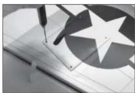
natural_image
Close-up of a sewing machine needle stitching a star-patterned fabric (no text or symbols visible)natural_image
Close-up of a hand holding a small electronic component with wires, no visible text or symbols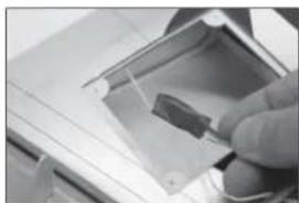
natural_image
Close-up of a hand inserting a small electronic component into a device (no visible text or symbols)
natural_image
Close-up of a metallic electronic device with a black cable inserted, showing internal components (no text or symbols visible)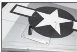
natural_image
Close-up of a mechanical device with a star-shaped component and a rectangular plate (no visible text or symbols)
natural_image
Close-up of a hand holding a small metallic object with a looped end (no visible text or symbols)natural_image
Close-up of a sewing machine needle stitching a white fabric (no text or symbols visible)
natural_image
Close-up of a hand holding a pen, with abstract geometric shapes and lines in the background (no readable text or symbols)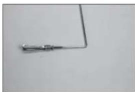
natural_image
Simple electrical circuit lines without any symbols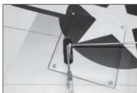
natural_image
Abstract geometric shapes with overlapping squares and diagonal lines, no text or symbols present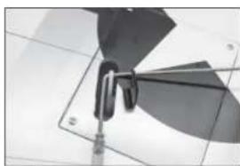
natural_image
Close-up of a metallic mechanical component with curved blades and mounting base (no visible text or symbols)natural_image
Close-up of a mechanical fan or propeller with blades and blades, mounted on a stand (no visible text or symbols)
natural_image
Close-up of a mechanical component with a circular base and triangular blades, no visible text or symbols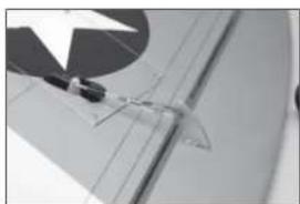
natural_image
Close-up of a document with a star symbol and faint lines, no readable text or symbols present.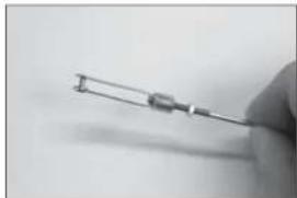
natural_image
Close-up of a hand holding a small cylindrical electronic component (no visible text or symbols)
natural_image
Close-up of a metallic mechanical bracket with mounting holes and a curved metal clip (no text or symbols visible)natural_image
Exterior view of a modern office building (no signage)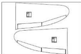
natural_image
Pure geometric diagram with curved and straight lines, no text or symbols present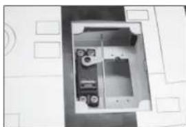
natural_image
Interior view of a room with furniture and doorways (no visible text or symbols)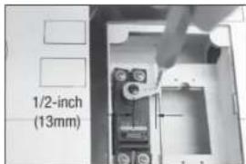
text_image
1/2-inch (13mm)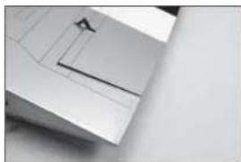
natural_image
Close-up of a metallic mechanical component with a small protrusion and a diagonal line (no visible text or symbols)natural_image
Close-up of a hand using a screwdriver to adjust or install electronic components on a circuit board (no visible text or symbols)
natural_image
Interior view of a mechanical or electronic device with no visible text, numbers, or symbols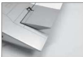
natural_image
Close-up of a white plastic sheet with a metal clip, no visible text or symbols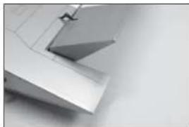
natural_image
Close-up of metallic architectural elements with no visible text or symbols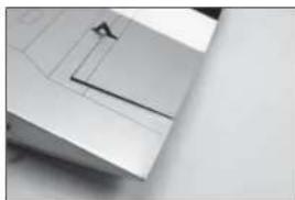
natural_image
Close-up of a metallic mechanical component with a small triangular feature and a diagonal line (no visible text or symbols)natural_image
Abstract geometric pattern with diagonal black bands and grid lines on a light background (no text or symbols)
natural_image
Close-up of a metallic mechanical component with no visible text or symbols
natural_image
Close-up of a jet aircraft nose section (no visible text or symbols)
natural_image
Close-up of a metallic tool tip with a pointed tip, no visible text or symbols
natural_image
Metal tool with a triangular tip and handle, shown against a plain background (no text or symbols visible)natural_image
Close-up of a metallic panel with white and black bands, showing internal cutouts and a small object (no text or symbols visible)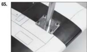
natural_image
Close-up of a sewing machine needle stitching fabric (no visible text or symbols)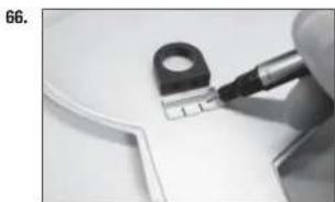
natural_image
Close-up of a hand using a tool to cut a small electronic component (no visible text or symbols)
natural_image
Close-up of a white electronic device with two connected ports and a curved edge (no visible text or symbols)
natural_image
Close-up of a metallic cylindrical object with black connectors, mounted on a wall (no visible text or symbols)natural_image
Close-up of a black circular object with a metallic knob, possibly a knob or knob (no text or symbols visible)70.

natural_image
Close-up of a hand holding a small black tire with a metallic screw (no visible text or symbols)71.
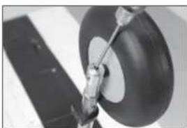
natural_image
Close-up of a mechanical component with a circular ring and attached rod (no visible text or symbols)72.
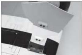
natural_image
Close-up of a kitchen appliance with a white oven and black handle (no visible text or symbols)73.
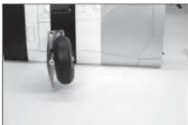
natural_image
Exterior view of a modern office building (no signage)□
INSTALLATION DU SYSTÈME DE RENTRÉE
natural_image
Close-up of a mechanical component with a circular opening and metallic parts (no visible text or symbols)75.
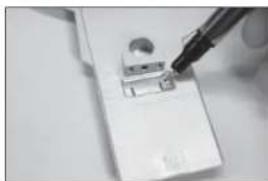
natural_image
Close-up of a hand using a pen to apply material to a small electronic component (no visible text or symbols)76.
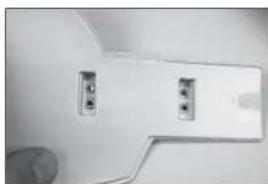
natural_image
Close-up of a white toilet or showerhead with two small buttons and a handle, no visible text or symbols.77.
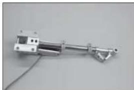
natural_image
Mechanical device with metallic shaft and attached bracket, shown against plain background (no text or symbols visible)78.
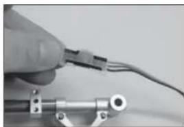
natural_image
Close-up of a hand holding a cable with wires, no visible text or symbolsnatural_image
Close-up of a computer monitor with a black plastic object inserted into a slot, showing ports and cables (no visible text or symbols)80.
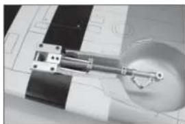
natural_image
Close-up of a mechanical component with a circular base and metallic parts, no visible text or symbols81.
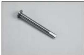
natural_image
Metal mechanical component with a pointed tip and threaded end (no text or symbols visible)82.

natural_image
Close-up of a black and white wheel rim with a central hub (no text or symbols visible)natural_image
Close-up of a mechanical tire with a central hub and side teeth (no visible text or symbols)84.
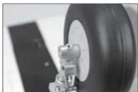
natural_image
Close-up of a tire mounted on a flat surface with a metal bracket (no visible text or symbols)85.
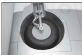
natural_image
Close-up of a mechanical component with a circular base and central shaft (no visible text or symbols)86.
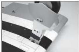
natural_image
Close-up of a sewing machine needle stitching fabric (no visible text or symbols)87.
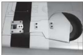
natural_image
Close-up of a mechanical component with black and white striped sections and a circular cutout (no visible text or symbols)natural_image
Close-up of a mechanical device with a black lever and circular component on a white surface (no visible text or symbols)natural_image
Close-up of a hand pointing at a grid-like object on a surface (no visible text or symbols)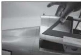
natural_image
Close-up of a hand interacting with a mechanical component (no visible text or symbols)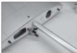
natural_image
Close-up of a metallic electronic device with a metallic clip and mounting bracket (no visible text or symbols)natural_image
Interior view of a bathroom with tiled walls and a small object on the floor (no visible text or symbols)
natural_image
Interior view of a modern office or library space with desks, chairs, and storage compartments (no visible text or symbols)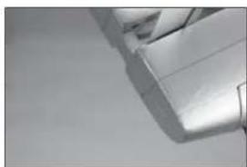
natural_image
Close-up of a metallic mechanical component with stepped edges and a flat surface (no visible text or symbols)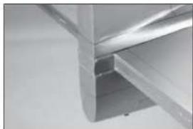
natural_image
Close-up of a metallic structural joint or bracket component (no visible text or symbols)
text_image
A A A=Anatural_image
Simple line drawing of an airplane viewed from above, with no text or symbols present.
text_image
A A A=A
natural_image
Close-up of a hand holding a pen over a white surface, possibly part of a mechanical or architectural component (no visible text or symbols)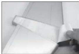
natural_image
Close-up of a rolled-up document or scroll with a hand holding it (no visible text or symbols)
natural_image
Close-up of a hand holding a paintbrush touching a white rectangular object (no text or symbols visible)natural_image
Close-up of a car door handle and seat area (no visible text or symbols)
natural_image
Close-up of a metallic structural joint or bracket detail (no text or symbols visible)
text_image
15/16 inch (24mm)
natural_image
Close-up of two gray plastic components with cutouts and mounting holes (no text or symbols visible)
natural_image
Close-up of a metallic cylindrical object with a curved edge and a flat surface, possibly part of a mechanical or architectural component (no visible text or symbols)text_image
15/16 inch (24mm)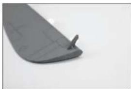
natural_image
Close-up of a dark gray plastic component with a small protrusion on the side (no visible text or symbols)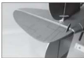
natural_image
Close-up of a propeller blade with a small handle, no visible text or symbols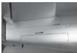
natural_image
Close-up of a white cylindrical object with a rectangular opening, possibly a vent or duct (no visible text or symbols)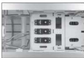
natural_image
Interior view of an electronic device showing multiple connected modules and wiring (no visible text or symbols)natural_image
Interior view of an electronic device with visible circuit boards and wiring (no readable text or symbols)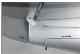
natural_image
Close-up of a mechanical component with no visible text or symbols
text_image
1/2-inch (13mm)
natural_image
Interior view of a modern office or hotel room with white furniture and ceiling fixtures (no visible text or symbols)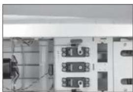
natural_image
Interior view of an electrical enclosure with visible circuitry and numbered components (no readable text or symbols)natural_image
Close-up of a jet engine component with visible blades and mounting features (no text or symbols)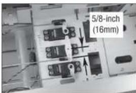
text_image
5/8-inch (16mm)☐ INSTALLATION DE L'ENSEMBLE DE ROUE DE119. QUEUE
natural_image
Close-up of a hand holding a small electronic component (no visible text or symbols)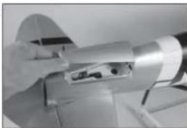
natural_image
Close-up of a hand holding a cylindrical mechanical component with a small inset showing internal components (no visible text or symbols)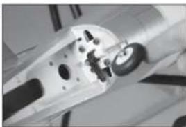
natural_image
Close-up of a mechanical component with visible internal parts and a central hub (no text or symbols)natural_image
Close-up of a white electrical socket with black components, mounted on a tiled wall (no visible text or symbols)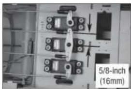
text_image
5/8-inch (16mm)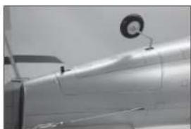
natural_image
Close-up of a metallic aircraft wing with a circular emblem on top (no visible text or symbols)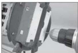
natural_image
Close-up of a mechanical component with a drill bit and a cylindrical head (no visible text or symbols)natural_image
Close-up of a metallic mechanical component with a coiled spring and handle (no visible text or symbols)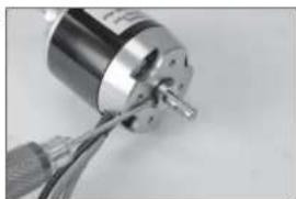
natural_image
Close-up of a metallic cylindrical mechanical component with a coiled cable, no visible text or symbols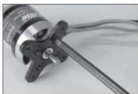
natural_image
Close-up of a mechanical component with a metallic shaft and attached housing (no visible text or symbols)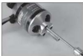
natural_image
Close-up of a mechanical component with a metallic shaft and cylindrical body (no visible text or symbols)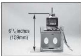
text_image
61/4 inches (159mm)natural_image
Close-up of hands using a tool to adjust or install a small electronic component (no visible text or symbols)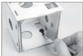
natural_image
Close-up of a hand inserting a small object into a white box-like device (no visible text or symbols)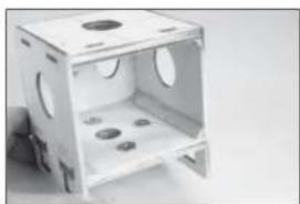
natural_image
Exterior view of a white plastic enclosure with circular cutouts and internal compartments (no text or symbols visible)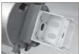
natural_image
Close-up of a mechanical component with a transparent housing and two circular holes (no visible text or symbols)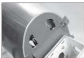
natural_image
Close-up of a metallic cylindrical mechanical component with mounting holes (no visible text or symbols)natural_image
Interior view of a computer setup with monitor, keyboard, and drive unit (no visible text or labels)147.
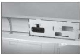
natural_image
Close-up of a white electronic device with a black internal component and a small rectangular slot (no visible text or symbols)148.
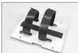
natural_image
Close-up of two black metal bracket components mounted on a white base plate (no text or symbols visible)149.

natural_image
Close-up of a mechanical component with black 3D lettering and mounting holes (no visible text or symbols)150.
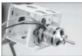
natural_image
Close-up of a mechanical device with a cylindrical component and wires, no visible text or symbolsnatural_image
Close-up of a mechanical device with internal components and wiring (no visible text or symbols)152.
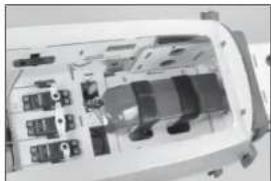
natural_image
Interior view of a vehicle's dashboard and engine compartment (no visible text or symbols)153.
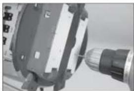
natural_image
Close-up of a mechanical component with a cylindrical tool inserted, no visible text or symbolsnatural_image
Close-up of a mechanical component with a tool inserted, no visible text or symbols155.
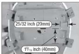
text_image
25/32 inch (20mm) 1½ inch (40mm)156.
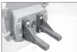
natural_image
Close-up of a mechanical clamp or bracket component (no visible text or symbols)157.

text_image
6½ inches (159mm)158.
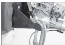
natural_image
Close-up of a mechanical assembly with hoses and components (no visible text or symbols)natural_image
Close-up of a mechanical tool with a drill bit inserted, no visible text or symbols160.
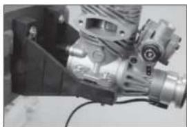
natural_image
Close-up of a mechanical engine component with visible gears and housing (no text or symbols)161.
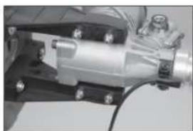
natural_image
Mechanical assembly showing a metallic cylindrical component with bolts and mounting brackets (no visible text or symbols)162.

natural_image
Close-up of a mechanical device with a lever mechanism (no visible text or symbols)163.

natural_image
Close-up of a metallic mechanical component with a circular housing and support structure (no visible text or symbols)natural_image
Interior view of a computer case with visible wiring and components (no text or symbols)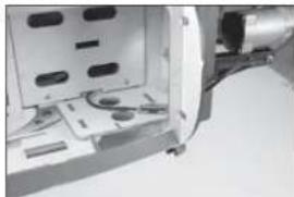
natural_image
Close-up of a mechanical device with internal components and mounting holes (no visible text or symbols)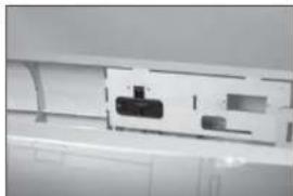
natural_image
Close-up of a white electronic device with internal components and connectors (no visible text or symbols)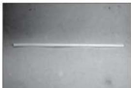
natural_image
A plain white cylindrical object on a neutral gray surface, no text or symbols visible.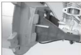
natural_image
Close-up of a mechanical assembly with no visible text or symbolsnatural_image
Close-up of a mechanical engine component with visible internal parts and shaft (no text or symbols)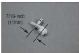
text_image
7/16-inch (11mm)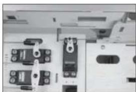
natural_image
Close-up of electronic components and connectors (no visible text or symbols)
natural_image
Close-up of a mechanical assembly with no visible text or symbols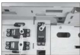
natural_image
Close-up of a mechanical or electronic component with multiple ports and connectors (no visible text or symbols)natural_image
Close-up of a mechanical pump or motor assembly (no visible text or symbols)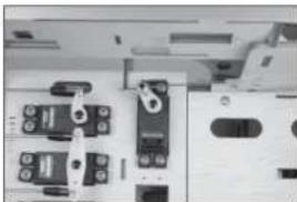
natural_image
Close-up of electronic components and connectors (no visible text or symbols)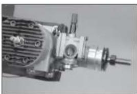
natural_image
Close-up of a mechanical assembly with gears and shafts (no visible text or symbols)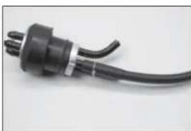
natural_image
Close-up of a black electrical plug with a coiled cable (no text or symbols visible)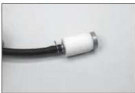
natural_image
Close-up of a black cable with white connector (no text or symbols visible)natural_image
Close-up of a black and white electrical connector with wires (no visible text or symbols)
natural_image
Close-up of a white plastic bottle with a black screwdriver inserted (no text or symbols visible)
natural_image
Close-up of a white electronic device with black connectors and wires (no visible text or symbols)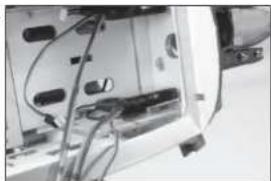
natural_image
Close-up of a mechanical device with visible internal components and wiring (no text or symbols)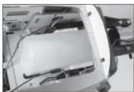
natural_image
Interior view of a vehicle chassis showing internal components and wiring (no visible text or symbols)natural_image
Interior view of a computer case showing internal components and storage areas (no visible text or symbols)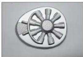
natural_image
Circular mechanical component with radial blades and central hub (no text or symbols)。
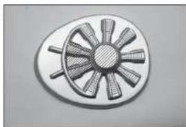
natural_image
Circular mechanical component with radial blades and central hub (no text or symbols)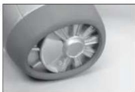
natural_image
Close-up of a metallic turbine or impeller component (no visible text or symbols)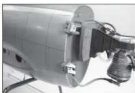
natural_image
Close-up of a mechanical device with visible wiring and components (no text or symbols)natural_image
Close-up of a metallic propeller or fan blade against a plain background (no text or symbols visible)
natural_image
Close-up of a metallic propeller or fan blade with a small protrusion, no visible text or symbols.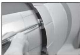
natural_image
Close-up of a mechanical component with a tool inserted, no visible text or symbols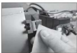
natural_image
Close-up of a hand holding a small electronic component with wires in the background (no visible text or symbols)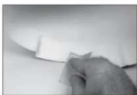
natural_image
Close-up of a hand holding a white sheet of paper on a plain surface (no text or symbols visible)natural_image
Close-up of a robotic arm operating a mechanical device (no visible text or symbols)195.
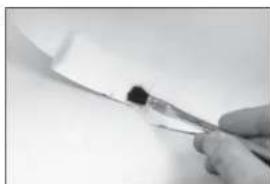
natural_image
Close-up of a gloved hand holding a small object with a black mark, against a plain white background (no text or symbols visible)196.
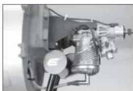
natural_image
Mechanical assembly diagram showing internal components and gears (no visible text or labels)197.
natural_image
Close-up of a mechanical component with a metallic knob and central shaft (no visible text or symbols)198.

natural_image
Close-up of a person inside a vehicle's seat frame (no visible text or symbols)natural_image
Close-up of a hand holding a metal tool interacting with a grid-patterned surface (no text or symbols visible)200.

natural_image
Close-up of a metallic mechanical component with interlocking parts (no visible text or symbols)201.
natural_image
Close-up of a white aircraft wing with a star emblem, no visible text or symbols202.
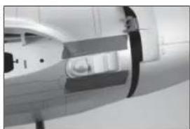
natural_image
Close-up of a medical imaging device with a transparent lens and screen (no visible text or symbols)203.

natural_image
Close-up of a camera lens and optical fiber assembly (no visible text or symbols)natural_image
Close-up of a mechanical component with black and white bands (no visible text or symbols)205.

natural_image
Close-up of a mechanical component with a hammerhead and star symbol, placed on a patterned surface (no visible text or symbols)206.
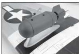
natural_image
Black-and-white photo of a missile on display with a star emblem in the background (no visible text or symbols)207.

natural_image
Close-up of a mechanical component with metallic parts and mounting holes (no visible text or symbols)208.

natural_image
Interior view of a minimalist room with dark cylindrical objects and a circular object on the wall (no visible text or symbols)natural_image
Close-up of a mechanical component with a metallic shaft and cylindrical head (no visible text or symbols)CENTRE DE GRAVITÉ
text_image
4-4½ inches (102-114mm)DÉBATTEMENTS
Atterrissage 45–55mm
□ CHECKLIST D'AVANT VOL
natural_image
Close-up of a white plastic sheet with a gray adhesive clip attached (no visible text or symbols)2.

natural_image
Simple line drawing of a fish-like shape with an arrow pointing to its body (no text or symbols)3.

natural_image
Close-up of a hand holding a small metallic clip against a plain background (no text or symbols visible)4.

natural_image
Simple geometric shape resembling a wedge or pinhole on a plain background (no text or symbols)5.
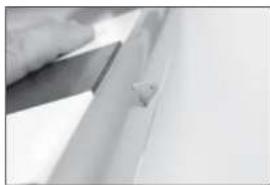
natural_image
Close-up of a hand holding a flat blade over a surface, with no visible text or symbolsnatural_image
Close-up of a metallic object with a black horizontal line and a white rectangular base (no text or symbols visible)7.
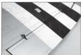
natural_image
Close-up of a striped surface with a small object near the edge (no text or symbols visible)8.
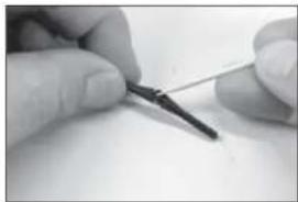
natural_image
Close-up of hands holding a pen, no visible text or symbols9.
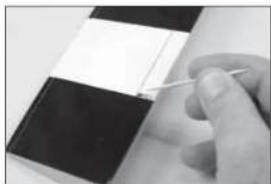
natural_image
Close-up of a hand holding a pen over a black and white striped surface (no text or symbols visible)natural_image
Close-up of hands holding a pen, no visible text or symbols11.
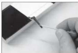
natural_image
Close-up of a hand holding a thin wire with a small object nearby (no visible text or symbols)12.
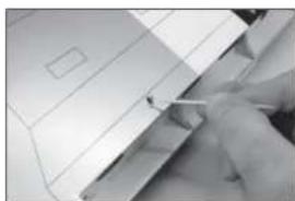
natural_image
Close-up of a hand holding a small object over a flat surface, possibly part of a device or tool (no visible text or symbols)13.
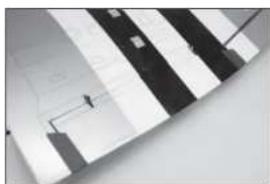
natural_image
Abstract geometric pattern with diagonal striped and rectangular shapes (no text or symbols)14.

natural_image
Close-up of a hand holding a small object over a document (no visible text or symbols)natural_image
Close-up of a metallic object with a star symbol on its surface (no text or symbols visible)16.

natural_image
Close-up of a hand holding a pen, partially visible through a white architectural or mechanical component (no text or symbols)17.

natural_image
Close-up of a metallic curved object with grid pattern, possibly a tool or component (no visible text or symbols)18.

natural_image
Abstract grayscale geometric pattern with diagonal stripes and a central dark band (no text or symbols)19.

natural_image
Close-up of a hand holding a small object over a grid-patterned surface, with no visible text or symbols.natural_image
Close-up of hands holding a document with a star emblem and grid paper (no visible text or symbols)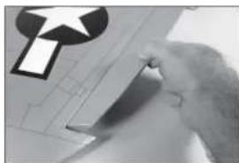
natural_image
Close-up of a hand holding a pen, with a large symbol on the left (no readable text or symbols)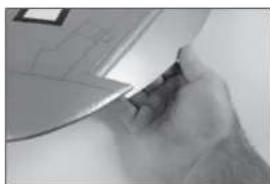
natural_image
Close-up of a hand holding a small object, possibly a tool or device, with no visible text or symbols.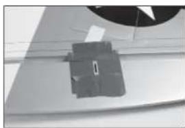
natural_image
Close-up of a mechanical component with a circular head and rectangular base (no visible text or symbols)
text_image
15/16 inch (24mm)natural_image
Close-up of hands holding a small object with a thin rod (no visible text or symbols)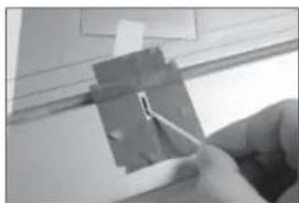
natural_image
Close-up of a hand holding a small electronic component with wires, no visible text or symbols
natural_image
Close-up of a hand using a tool to cut or mark a metallic component (no visible text or symbols)E28.
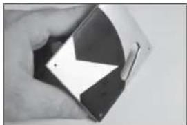
natural_image
Close-up of a hand holding a smartphone with a black and white abstract design (no visible text or symbols)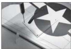
natural_image
Close-up of a sewing machine needle stitching a star-patterned sheet (no text or symbols visible)natural_image
Close-up of a metallic architectural structure with angular and radial elements (no text or symbols visible)31.
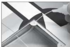
natural_image
Close-up of a mechanical component with metallic blades and a tool, no visible text or symbols32.
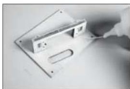
natural_image
Close-up of a hand holding a white electronic device with a rectangular panel and a U-shaped slot (no visible text or symbols)33.

natural_image
Close-up of a hand using a tool to adjust or install electronic components on a white surface (no visible text or symbols)34.

natural_image
Close-up of a small electronic device component with a metallic housing and mounting bracket (no visible text or symbols)natural_image
Close-up of a hand holding a small electronic component with wires, no visible text or symbols36.
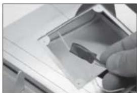
natural_image
Close-up of a hand holding a small electronic device with a screen (no visible text or symbols)37.
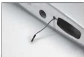
natural_image
Close-up of a metallic electronic device with a black cable inserted, showing internal components and a small inset (no text or symbols visible)38.
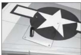
natural_image
Close-up of a mechanical device with a star-shaped component and a rectangular block, no visible text or symbols.39.

natural_image
Close-up of a hand holding a small metallic tool with a small component, against a plain background (no text or symbols visible)natural_image
Close-up of a sewing machine needle stitching fabric (no text or symbols visible)
natural_image
Close-up of a hand using a pen to write on a chart (no visible text or symbols)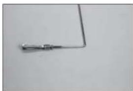
natural_image
Simple electrical component with a bent wire and terminal block (no text or symbols visible)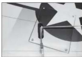
natural_image
Abstract geometric shapes with overlapping squares and diagonal lines, no text or symbols present
natural_image
Close-up of a mechanical component with curved and straight elements, possibly a valve or clamping mechanism (no visible text or symbols)natural_image
Close-up of a mechanical fan or propeller with blades and blades, no visible text or symbols
natural_image
Close-up of a mechanical component with a circular base and triangular tip, no visible text or symbols
natural_image
Close-up of a mechanical component with a star-like symbol and angled features (no visible text or symbols)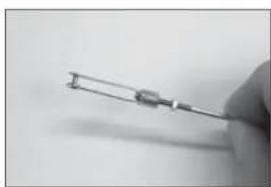
natural_image
Close-up of a hand holding a small metallic tool or wire (no visible text or symbols)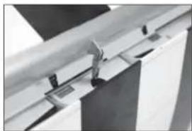
natural_image
Close-up of a metal rail or pipe assembly with a clamp, no visible text or symbolsnatural_image
Abstract geometric pattern with a central dark figure and surrounding grid-like shapes (no text or symbols)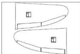
natural_image
Pure geometric diagram with curved and straight lines, no text or symbols present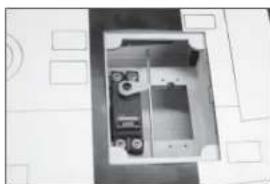
natural_image
Interior view of a room with shelves and equipment (no visible text or symbols)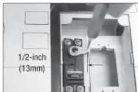
text_image
1/2-inch (13mm)
natural_image
Close-up of a metallic mechanical component with a diagonal seam and arrow (no visible text or symbols)natural_image
Close-up of a hand using a screwdriver to adjust or install electronic components inside a device casing (no visible text or symbols)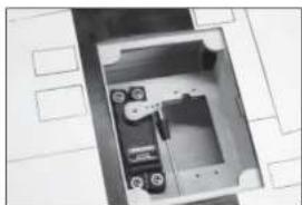
natural_image
Interior view of a mechanical or electronic device with no visible text, numbers, or symbols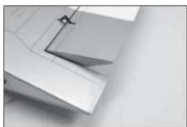
natural_image
Close-up of a metallic mechanical component with a triangular cutout and mounting bracket (no visible text or symbols)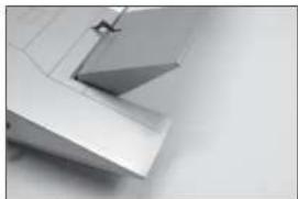
natural_image
Close-up of metallic architectural elements with no visible text or symbols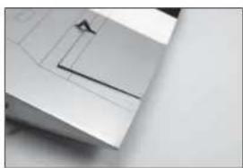
natural_image
Close-up of a white mechanical component with a diagonal line and a small triangular feature (no text or symbols visible)natural_image
Abstract geometric shapes and grid patterns on a white background, no text or symbols visible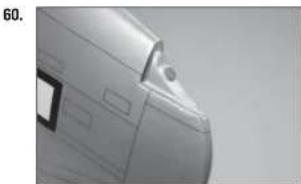
natural_image
Close-up of a white car's side profile with visible door and window (no text or symbols)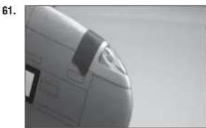
natural_image
Close-up of a white aircraft fuselage with visible structural details (no text or symbols)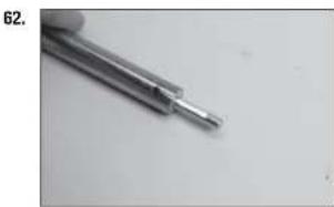
natural_image
Close-up of a metallic screwdriver tip against a plain background (no text or symbols visible)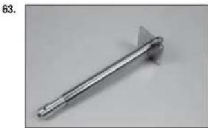
natural_image
Metal tool with triangular tip and handle, no visible text or symbolsnatural_image
Close-up of a metallic mechanical component with white and black sections, no visible text or symbols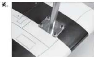
natural_image
Close-up of a sewing machine needle stitching a curved fabric (no visible text or symbols)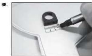
natural_image
Close-up of a hand using a pen to cut a small electronic component (no visible text or symbols)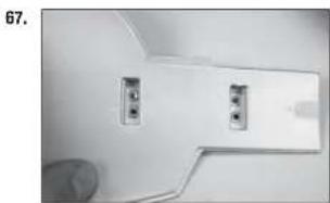
natural_image
Close-up of a white wall-mounted electrical outlet with two outlets, no visible text or symbols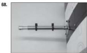
natural_image
Close-up of a metallic cylindrical object with black connectors, possibly a tool or device (no visible text or symbols)natural_image
Close-up of a black circular object with a metallic knob, possibly a knob or knob (no text or symbols visible)70.
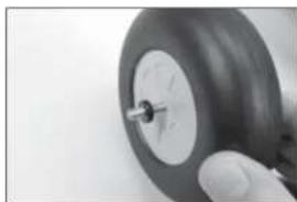
natural_image
Close-up of a hand holding a small black tire with a metallic screw (no visible text or symbols)71.
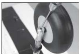
natural_image
Close-up of a mechanical component with a circular head and attached rod (no visible text or symbols)72.
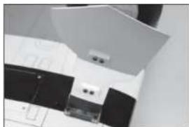
natural_image
Close-up of a mechanical component with no visible text or symbolsnatural_image
Close-up of a dark, oval-shaped object on a white surface with a black panel in the background (no visible text or symbols)74.
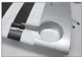
natural_image
Close-up of a mechanical component with a circular opening and two protruding rods (no visible text or symbols)75.
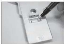
natural_image
Close-up of a sewing machine needle stitching a small component (no visible text or symbols)76.
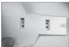
natural_image
Close-up of a white plastic door panel with two small buttons and a finger pointing to it (no text or symbols visible)natural_image
Mechanical component with attached rod and wires, no visible text or symbols78.
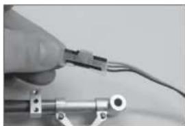
natural_image
Close-up of a hand holding a small electronic component with wires, no visible text or symbols79.
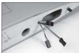
natural_image
Close-up of a computer monitor with a black plastic fan and attached cable (no visible text or symbols)80.
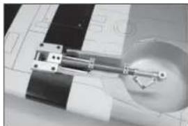
natural_image
Close-up of a mechanical assembly with a circular component and a metallic sphere (no visible text or symbols)81.
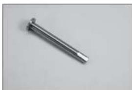
natural_image
Metal mechanical component with a pointed tip, isolated on a plain background (no text or symbols visible)natural_image
Close-up of a black tire with a white circular rim and a central hole (no text or symbols visible)83.
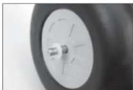
natural_image
Close-up of a car wheel rim with visible tire and hub (no text or symbols)84.
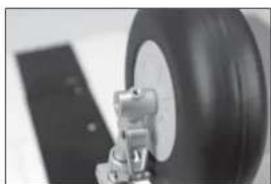
natural_image
Close-up of a mechanical component with a large tire and attached bracket (no visible text or symbols)85.
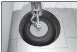
natural_image
Close-up of a mechanical component with a circular base and central shaft (no visible text or symbols)natural_image
Close-up of a sewing machine needle stitching fabric (no visible text or symbols)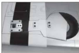
natural_image
Pure electrical circuit lines without any symbols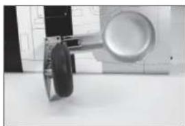
natural_image
Close-up of a mechanical device with a circular component mounted on a table, no visible text or symbols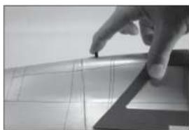
natural_image
Close-up of a hand pressing down on a curved surface with grid lines (no text or symbols visible)natural_image
Close-up of a hand interacting with a mechanical component (no visible text or symbols)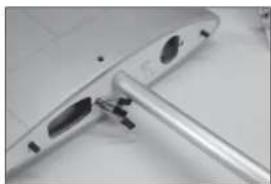
natural_image
Close-up of a metallic electronic device with a cylindrical port and internal components (no visible text or symbols)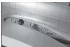
natural_image
Interior view of a bathroom with tiled walls and a curved glass fixture (no visible text or symbols)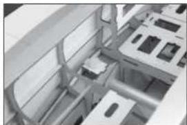
natural_image
3D rendered mechanical assembly with no visible text or symbols
natural_image
Close-up of a metallic mechanical component with no visible text or symbolsnatural_image
Close-up of a metallic structural joint or bracket (no text or symbols visible)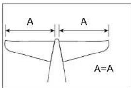
text_image
A A A=A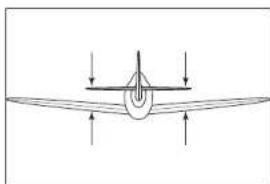
natural_image
Simple line drawing of an airplane viewed from above, with no text or symbols present.
text_image
A A A=A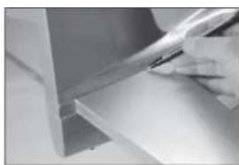
natural_image
Close-up of a hand using a tool to cut or mark a white surface, no visible text or symbolsnatural_image
Close-up of a rolled-up sheet of paper or paper with a hand partially visible (no text or symbols)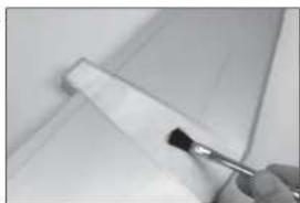
natural_image
Close-up of a hand holding a brush applying paint to a white panel, no visible text or symbols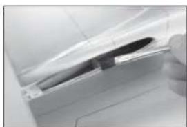
natural_image
Close-up of a white car door handle with a dark plastic clip, no visible text or symbols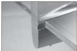
natural_image
Close-up of a metallic structural joint or bracket (no text or symbols visible)
text_image
15/16 inch (24mm)natural_image
Close-up of a mechanical component with two white components, no visible text or symbols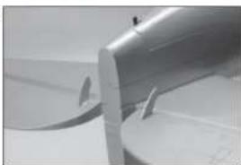
natural_image
Close-up of a metallic cylindrical object with a pointed tip and circular base, no visible text or symbols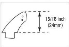
text_image
15/16 inch (24mm)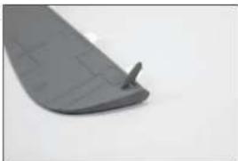
natural_image
Close-up of a gray plastic curved object with a small protrusion on the side (no text or symbols visible)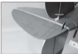
natural_image
Close-up of a propeller blade with a curved handle and mounting bracket (no visible text or symbols)
INSTALLAZIONE DEI SERVO DI ELEVATORE E110. MONE
natural_image
Close-up of a mechanical component with no visible text or symbols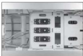
natural_image
Interior view of an electronic device showing multiple connected modules and wiring (no visible text or symbols)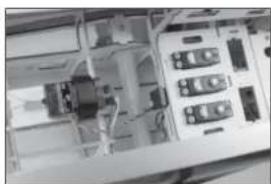
natural_image
Interior view of an electronic device with visible circuit boards and wiring (no readable text or symbols)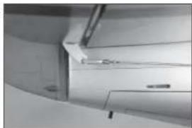
natural_image
Interior view of a curved room with horizontal panels and a small fixture (no visible text or symbols)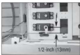
text_image
1/2-inch (13mm)natural_image
Interior view of a modern kitchen appliance with tiled walls and a door handle (no visible text or symbols)116.
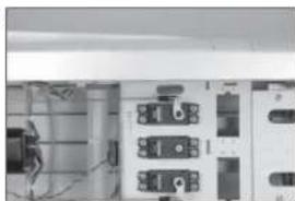
natural_image
Interior view of an electrical cabinet or enclosure with visible wiring and circuit breakers (no text or symbols)117.
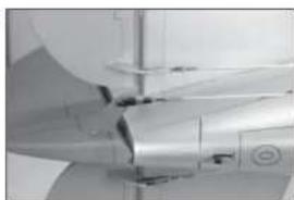
natural_image
Close-up of a jet engine component with visible blades and mounting brackets (no text or symbols)118.
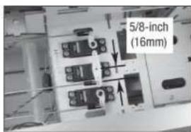
text_image
5/8-inch (16mm)119.
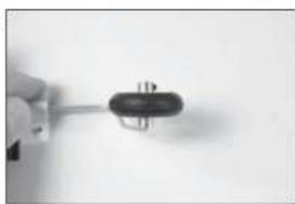
natural_image
Close-up of a hand holding a small electronic component (no visible text or symbols)natural_image
Close-up of a hand holding a metallic cylindrical device with a small inset showing internal components (no visible text or symbols)121.
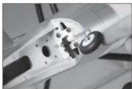
natural_image
Close-up of a mechanical component with visible gears and joints (no text or symbols)122.
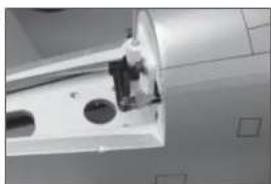
natural_image
Close-up of a mechanical component with two circular holes and a central housing (no visible text or symbols)123.
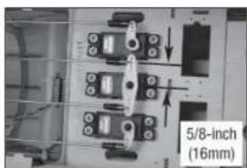
natural_image
Close-up of electronic components with a 5/8-inch (16mm) dimension label, no readable text or symbols beyond the measurement annotation.124.
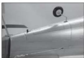
natural_image
Close-up of a metallic aircraft wing with a circular component attached (no visible text or symbols)☐ INSTALLAZIONE DEL MOTORE ELETTRICO
natural_image
Close-up of a mechanical component with a cylindrical shaft and housing (no visible text or symbols)126.

natural_image
Close-up of a mechanical component with a circular housing and a cylindrical shaft (no visible text or symbols)127.
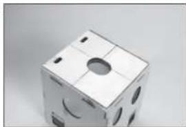
natural_image
3D rendered cube with cutouts and mounting holes (no text or symbols)128.
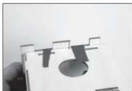
natural_image
Close-up of a hand holding a small object with abstract geometric shapes (no text or symbols visible)natural_image
Close-up of a mechanical component being cut with a tool, no visible text or symbols130.
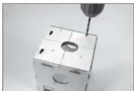
natural_image
Close-up of a mechanical component with a screwdriver inserted into a grid (no visible text or symbols)131.

natural_image
Close-up of hands using a tool to adjust a black mechanical component (no visible text or symbols)132.
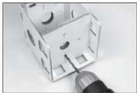
natural_image
Close-up of a small mechanical component with cutouts and a metallic tool inserted (no visible text or symbols)133.
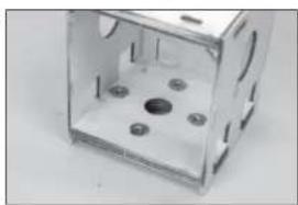
natural_image
Exterior view of a transparent plastic enclosure with multiple bolt holes (no text or symbols visible)natural_image
Close-up of a white electrical outlet box mounted on a cylindrical base (no visible text or symbols)145.
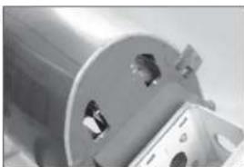
natural_image
Close-up of a metallic mechanical component with circular holes and a flanged base (no visible text or symbols)146.
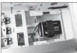
natural_image
Interior view of a computer setup with monitor, keyboard, and drive unit (no visible text or labels)147.
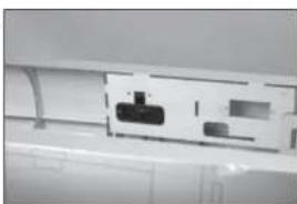
natural_image
Close-up of a white electronic device with a black internal component and ventilation duct (no visible text or symbols)148.
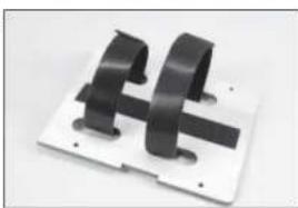
natural_image
Close-up of two black metal bracket components mounted on a white plate (no text or symbols visible)text_image
Close-up of a cylindrical object with embossed Chinese characters and small cutouts, likely from a technical or educational material.150.
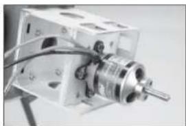
natural_image
Close-up of a mechanical device with a metallic cylindrical component and wiring (no visible text or symbols)151.
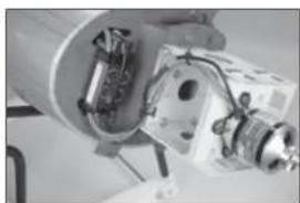
natural_image
Close-up of a mechanical device with internal components and wiring (no visible text or symbols)152.
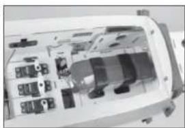
natural_image
Interior view of a device casing with internal compartments and connectors (no visible text or symbols)☐ INSTALLAZIONE DEL MOTORE A BENZINA
natural_image
Close-up of a mechanical component with a cylindrical tool inserted, no visible text or symbols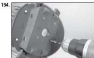
natural_image
Close-up of a mechanical component with a tool inserted, no visible text or symbols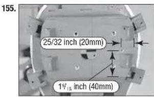
text_image
155. 25/32 inch (20mm) 1½ inch (40mm)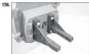
natural_image
Close-up of a mechanical clamp or bracket component (no visible text or symbols)text_image
157. 6½ inches (159mm)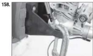
natural_image
Close-up of a mechanical assembly with a pipe and valve (no visible text or symbols)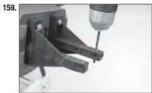
natural_image
Close-up of a mechanical tool with a drill bit inserted, no visible text or symbols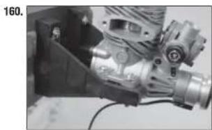
natural_image
Close-up of a mechanical assembly with gears and housing (no visible text or symbols)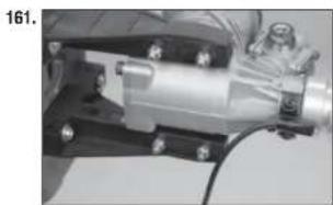
natural_image
Mechanical assembly with metallic components and bolts (no visible text or symbols)natural_image
Close-up of a mechanical device with a lever and handle (no visible text or symbols)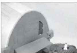
natural_image
Close-up of a metallic mechanical component with a curved top and internal slot (no visible text or symbols)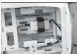
natural_image
Interior view of a computer case showing internal components and wiring (no visible text or symbols)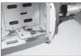
natural_image
Close-up of a mechanical component with internal parts and mounting holes (no visible text or symbols)natural_image
Close-up of a white electronic device with a black connector and ventilation slots (no visible text or symbols)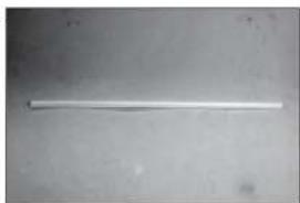
natural_image
A plain white cylindrical object on a plain gray surface, no text or symbols visible.
natural_image
Close-up of a mechanical component with no visible text or symbols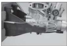
natural_image
Close-up of a mechanical component with no visible text or symbols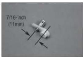
text_image
7/16-inch (11mm)natural_image
Close-up of electronic components with no visible text or symbols172.

natural_image
Close-up of a mechanical assembly with gears and shafts (no visible text or symbols)173.
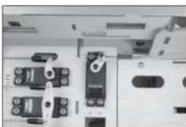
natural_image
Close-up of a mechanical or electronic component with multiple ports and connectors (no visible text or symbols)174.
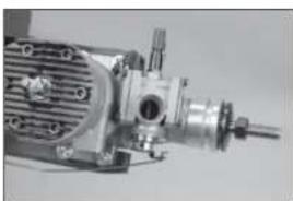
natural_image
Close-up of a mechanical pump or motor assembly (no visible text or symbols)175.

natural_image
Close-up of electronic components including connectors and switches (no visible text or symbols)natural_image
Close-up of a mechanical device with cooling fan and shaft (no visible text or symbols)177.
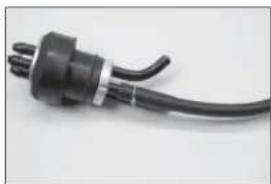
natural_image
Close-up of a black electrical plug with a coiled cable (no text or symbols visible)178.

natural_image
Close-up of a black cable with white connector (no text or symbols visible)179.

natural_image
Close-up of a black and white electrical connector with wires (no visible text or symbols)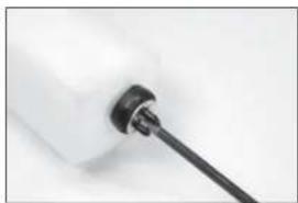
natural_image
Close-up of a white plastic bottle with a black screwdriver inserted (no text or symbols visible)natural_image
Close-up of a white electronic device with black connectors and wires (no visible text or symbols)
natural_image
Interior view of a device showing internal components and wiring (no visible text or symbols)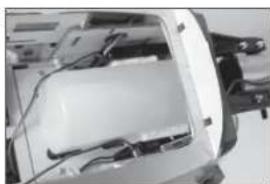
natural_image
Interior view of a vehicle chassis showing internal components and wiring (no visible text or symbols)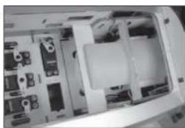
natural_image
Interior view of a computer case showing internal components and casing (no visible text or labels)
natural_image
Illustration of a fan-shaped mechanical component with radial blades and central hub (no text or symbols)natural_image
Illustration of a circular fan with radial blades, no text or symbols present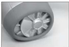
natural_image
Close-up of a mechanical component with radial blades and central hub (no visible text or symbols)
natural_image
Close-up of a mechanical device with attached components and wiring (no visible text or symbols)
natural_image
Close-up of a metallic propeller or fan blade against a plain background (no text or symbols visible)
natural_image
Close-up of a metallic propeller or fan blade with a central hub (no visible text or symbols)natural_image
Close-up of a hand using a tool to adjust or install a white cylindrical component (no visible text or symbols)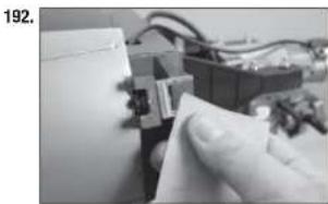
natural_image
Close-up of a hand holding a small electronic component with wires in the background (no visible text or symbols)
natural_image
Close-up of a hand holding a white paper with a curled edge, no visible text or symbols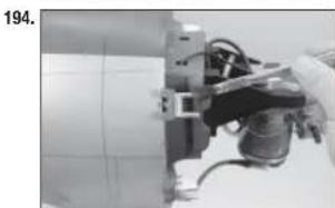
natural_image
Close-up of a mechanical assembly with wires and components, no visible text or symbolsnatural_image
Close-up of a gloved hand holding a pen with a black ink mark, against a plain white background (no text or symbols visible)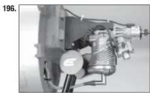
natural_image
Mechanical assembly diagram showing internal components and gears (no visible text or labels)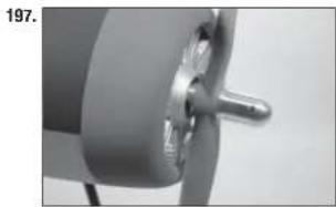
natural_image
Close-up of a mechanical component with a metallic knob and circular base (no visible text or symbols)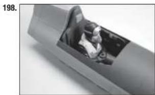
natural_image
Close-up of a mechanical component with a visible internal opening, no text or symbols present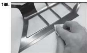
natural_image
Close-up of a hand holding a metallic object with grid-like structure (no visible text or symbols)natural_image
Close-up of a metallic mechanical component with internal components (no visible text or symbols)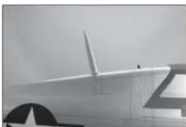
natural_image
Side profile of a white aircraft fuselage with star insignia (no visible text or symbols)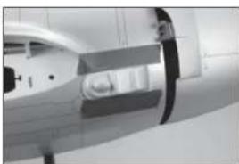
natural_image
Close-up of a medical imaging device with no visible text or symbols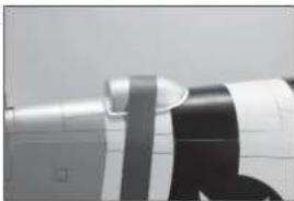
natural_image
Close-up of a mechanical component with a metallic tool and black bands (no visible text or symbols)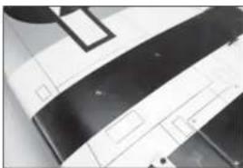
natural_image
Close-up of a white and black electronic device with no visible text or symbolsnatural_image
Close-up of a sewing machine needle stitching fabric with star pattern (no visible text or symbols)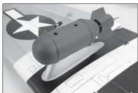
natural_image
Black-and-white photo of a military bomb on display with a star emblem in the background (no visible text or symbols)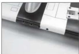
natural_image
Close-up of a mechanical component with a metallic cylindrical part inserted, showing no visible text or symbols.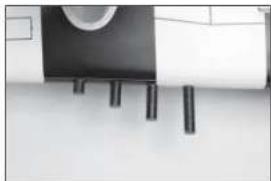
natural_image
Interior view of a modern kitchen appliance with cylindrical fixtures and a wall-mounted dish (no visible text or symbols)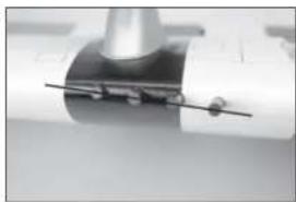
natural_image
Close-up of a mechanical component with a cylindrical shaft and a metallic end (no visible text or symbols)BARICENTRO
text_image
4-4½ inches (102-114mm)CORSE DEI COMANDI
text_image
58½-inches (1485.90mm) 55½-inches (1409.70mm)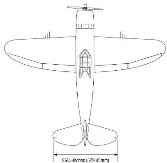
natural_image
Line drawing of a vintage propeller airplane with labeled dimensions (26½-inches, 679.45mm) — no text or symbols on the diagram itself.HANGAR 9®
© 2017 Horizon Hobby, LLC.
Hangar 9, Evolution, AS3X, EC5 and the Horizon Hobby logo are trademarks or registered trademarks of Horizon Hobby, LLC. The Spektrum trademark is used with permission of Bachmann Industries, Inc. All other trademarks, service marks and logos are the property of their respective owners.
54929
Created
10/2017