Ki43 Oscar 60cc - Remote control toy Hangar 9 - Free user manual and instructions
Find the device manual for free Ki43 Oscar 60cc Hangar 9 in PDF.
User questions about Ki43 Oscar 60cc Hangar 9
0 question about this device. Answer the ones you know or ask your own.
Ask a new question about this device
Download the instructions for your Remote control toy in PDF format for free! Find your manual Ki43 Oscar 60cc - Hangar 9 and take your electronic device back in hand. On this page are published all the documents necessary for the use of your device. Ki43 Oscar 60cc by Hangar 9.
USER MANUAL Ki43 Oscar 60cc Hangar 9
All instructions, warranties and other collateral documents are subject to change at the sole discretion of Horizon Hobby, LLC. For up-to-date product literature, visit horizonhobby.com or www.towerhobbies.com and click on the support or resources tab for this product.
MEANING OF SPECIAL LANGUAGE
The following terms are used throughout the product literature to indicate various levels of potential harm when operating this product:
WARNING: Procedures, which if not properly followed, create the probability of property damage, collateral damage, and serious injury OR create a high probability of superficial injury.
CAUTION: Procedures, which if not properly followed, create the probability of physical property damage AND a possibility of serious injury.
NOTICE: Procedures, which if not properly followed, create a possibility of physical property damage AND a little or no possibility of injury.

WARNING: Read the ENTIRE instruction manual to become familiar with the features of the product before operating. Failure to operate the product correctly can result in damage to the product, personal property and serious injury.
This is a sophisticated hobby product. It must be operated with caution and common sense and requires some basic mechanical ability. Failure to operate this Product in a safe and responsible manner could result in injury or damage to the product or other property. This product is not intended for use by children without direct adult supervision. Do not attempt disassembly, use with incompatible components or augment product in any way without the approval of Horizon Hobby, LLC. This manual contains instructions for safety, operation and maintenance. It is essential to read and follow all the instructions and warnings in the manual, prior to assembly, setup or use, in order to operate correctly and avoid damage or serious injury.
Age Recommendation: Not For Children Under 14 Years. This Is Not A Toy.
SAFETY WARNINGS AND PRECAUTIONS
Read and follow all Instructions and safety precautions before use. Improper use can result in fire, serious injury and damage to property.
Components
Use only with compatible components. Should any compatibility questions exist, please refer to the product instructions, component instructions or contact the appropriate Horizon Hobby office.
Flight
Fly only in open areas to ensure safety. It is recommended fl ying be done at radio control fl ying fi elds. Consult local ordinances before choosing a fl ying location.
Propeller
Always keep loose items that can become entangled in the propeller away from the prop. This includes loose clothing or other objects such as pencils and screwdrivers. Keep your hands away from the propeller as injury can occur.
Batteries
Always follow the manufacturer's instructions when using and disposing of any batteries. Mishandling of Li-Po batteries can result in fire causing serious injury and damage.
Small Parts
This kit includes small parts and should not be left unattended near children as choking and serious injury could result.
SAFE OPERATING RECOMMENDATIONS
- Inspect your model before every flight to ensure it is airworthy.
- Be aware of any other radio frequency user who may present an interference problem.
• Always be courteous and respectful of other users in your selected flight area. - Choose an area clear of obstacles and large enough to safely accommodate your flying activity.
- Make sure this area is clear of friends and spectators prior to launching your aircraft.
- Be aware of other activities in the vicinity of your flight path that could cause potential conflict.
- Carefully plan your flight path prior to launch.
- Abide by any and all established AMA National Model Aircraft Safety Code.
BEFORE STARTING ASSEMBLY
- Remove parts from bag.
- Inspect fuselage, wing panels, rudder and stabilizer for damage.
- If you find damaged or missing parts, contact your place of purchase.
- Charge transmitter and receiver batteries.
• Center trims and sticks on your transmitter. - For a computer radio, create a model memory for this particular model.
- Bind your transmitter and receiver, using your radio system's instructions.
NOTICE: Rebind the radio system once all control throws are set. This will keep the servos from moving to their endpoints until the transmitter and receiver connect. It will also guarantee the servo reversal settings are saved in the radio system.
FAA INFORMATION
If you own this product, you may be required to register with the FAA.
For up-to-date information on how to register with the FAA, please visit https://registermyuas.faa.gov/.
For additional assistance on regulations and guidance on UAS usage, visit knowbeforeyoufl y.org/.
TABLE OF CONTENTS
| Notice | 2 |
| Meaning of Special Language | 2 |
| Safety Warnings and Precautions | 2 |
| Safe Operating Recommendations | 2 |
| Before Starting Assembly | 2 |
| FAA Information | 2 |
| Replacement Parts | 3 |
| Required Adhesives | 3 |
| Required for Completion, All Power Options | 4 |
| Required for Completion, Gas Engine Installation | 4 |
| Required for Completion, Electric Motor Installation | 4 |
| Optional Parts | 4 |
| Tools Required | 4 |
| Printed Covering Notes | 5 |
| Building Precautions | 5 |
| Transportation and Storage | 5 |
| Checking Blind Nuts | 5 |
| Nose Weight | 5 |
| For the Visually Challenged | 5 |
| Retract Installation | 5 |
| Alleron Installation | 9 |
| Hinging the Ailerons | 11 |
| Alleron Servo Installation | 12 |
| Hinging the Flaps | 14 |
| Flap Servo Installation | 15 |
| Drop Tank Installation | 17 |
| Stabilizer Installation | 18 |
| Elevator Installation | 20 |
| Rudder Installation | 21 |
| Rudder Linkage Installation | 21 |
| Tail Wheel Installation | 22 |
| Pilot and Canopy Installation | 24 |
| Electric Motor Installation | 25 |
| Gas Engine Installation | 27 |
| Fuel Tank Installation | 29 |
| Retract Air System Installation | 30 |
| Receiver Installation | 32 |
| Cowling and Spinner Installation | 32 |
| Center of Gravity | 34 |
| Control Throws | 35 |
| Preflight Checklist | 35 |
| Daily Flight Checks | 35 |
| Limited Warranty | 35 |
| Warranty and Service Contact Information | 36 |
| Instructions for Disposal of WEEE by Users in the European Union | 36 |
| Academy of Model Aeronautics National Model Aircraft Safety Code | 37 |
REPLACEMENT PARTS
| Part # Description | |
| HAN472001 KI-43 | Oscar 60cc Airframe Only |
| HAN472002 Fuselage with Hatch: Ki-43 60cc | |
| HAN472003 LH Wing with Aileron & Flap: Ki-43 60cc | |
| HAN472004 RH Wing with Aileron & Flap: Ki-43 60cc | |
| HAN472005 Stabilizer with Elevator: KI-43 60cc | |
| HAN472006 Rudder: Ki-43 60cc | |
| HAN472007 Cowling & Dummy Engine:Ki-43 60cc | |
| HAN472008 Top Hatch: KI-43 60cc | |
| HAN472009 Canopy: Ki-43 60cc | |
| HAN472010 Painted Pilot: KI-43 60cc | |
| HAN472011 Hardware Set: Ki-43 60cc | |
| HAN472012 Mainwheels 5-inch: Ki-43 60cc | |
| HAN472013 Tail Wheel Assembly: KI-43 60cc | |
| HAN472014 Pushrod Set: Ki-43 60cc | |
| HAN472015 Spinner 3 34 -inch: Ki-43 60cc | |
| HAN472016 Wing Tube: KI-43 60cc | |
| HAN472017 Fuel Tank: KI-43 60cc | |
| HAN472018 EP Motor Mount: Ki-43 60cc | |
| HAN472019 Gear Door Set: Ki-43 60cc | |
| HAN472020 Scale Details: KI-43 60cc | |
| HAN472025 Retract Set: KI-43 60cc | |
| HAN472026 Retracts and Struts: KI-43 60cc | |
| HAN472027 Air System Hardware: Ki-43 60 cc | |
| HAN472028 Retract Struts: Ki-43 60cc | |
REQUIRED ADHESIVES
| Description |
| 15-minute epoxy |
| 30-minute epoxy |
| Thin CA |
| Medium CA |
| Threadlock, low and high strength |
REQUIRED FOR COMPLETION, ALL POWER OPTIONS
| # Required Part # Description | ||
| 1 | SPMAR1231 | OT AR12310T 12CH Power Safe Tele RX |
| 7 | SPMSA6320 | A6320 H-T/H-S Brushless HV Servo |
| 1 | SPMSA6110 | A6110 M-T / M-S Standard HV Servo (retract air valve) |
| 2 | SPMA3000 | Heavy-Duty Servo Extension 3-inch |
| 4 | SPMA3002 | Heavy-Duty Servo Extension 9-inch |
REQUIRED FOR COMPLETION, GAS ENGINE INSTALLATION
| # Required Part # Description | ||
| 2 SPMSA6110 | A6110 M-T / M-S Standard | HV Servo (throttle and choke) |
| 1 DLEG0061 | DLE-61cc Gas Engine w/Elec | Ignition |
| 1 DUB800 Tygon | Gas Tubing, 3' Large | |
| 1 HAN116 Fuld | Filler with "T" and Overfl ow Fittings | |
| 1 SPM9530 | Spektrum 3-Wire Switch Harness | |
| 3 SPMB4000L | PRX 4000mAh 2S 7.4V LiPo Rx Battery | |
REQUIRED FOR COMPLETION, ELECTRIC MOTOR INSTALLATION
| # Required Part # Description | ||
| 1 GPMG4805 | Rimfi re 65cc Electric Motor | |
| 1 CSE010013100 | Talon HV120 | ESC 010-0131-00 |
OPTIONAL PARTS
| Part # | Description |
| EVOA100 | Optical Ignition Kill Switch |
| SAIEG90R3 | FG-90R3 90cc 3-Cyl Radial Engine |
| SPMAS3000 | AS3000 AS3X Stabilization Module |
TOOLS REQUIRED
| Description |
| Adjustable wrench |
| Balancing stand |
| Box wrench: 14mm and 17mm |
| Crimping tool |
| Drill and tap set, metric |
| Drill bit set, Imperial or Metric |
| Epoxy brushes |
| Felt-tipped pen |
| Hemostats |
| Hex wrench set, Imperial and Metric |
| Hobby knife with #11 blade |
| Hobby scissors |
| Hook and loop straps |
| Hook and loop tape |
| Isopropyl alcohol |
| Light machine oil |
| Low-tack tape |
| Mixing sticks |
| Needle nose pliers |
| Nut driver set, Imperial and Metric |
| Paper towels |
| Pencil |
| Petroleum jelly |
| Phillips screwdriver: #1, #2 |
| Pin vise |
| Razor saw |
| Rotary tool |
| Ruler |
| Sanding bar |
| Sanding drum for rotary tool |
| Sandpaper |
| Scissors |
| Side cutters |
| Square |
| Tap handle |
| Tapered reamer |
| Tie wraps |
| Toothpicks |
| Wire stripper |
PRINTED COVERING NOTES
- The covering used on your model has the coloring and markings printed directly on the covering.
- The covering has a self-adhesive backing, and it is not recommended to use heat as it may damage the covering.
- Use only mild cleaning agents on the printed finish. Denatured alcohol is the most aggressive agent we recommend, but test on an inconspicuous area fi rst. Prolonged use will remove the paint.
- Use tape with care. Anything other than low-tack tape can remove the finish, particularly on edges.
- Avoid contact with raw fuel, especially alcohol-based fuels containing nitro methane.
- Remove exhaust residue as soon as practical to avoid staining or damaging of the fi nish.
There are two areas on your aircraft that will receive wear under normal use. The fi rst area is where the cowling fi ts over the fuselage hatch, and where the wing fi ts into the fuselage. Placing a piece of clear tape on the wing where it fi ts into the fuselage, and on the hatch underneath the cowling, will reduce the wear on the covering in these areas. Sanding the inside of the cowling smooth will also help prevent wear of the covering under the cowling.
BUILDING PRECAUTIONS
Prepare the work surface prior to beginning the build. The surface should be soft and free of any sharp objects. We recommend resting the airframe parts on a soft towel or pit mat to prevent scratching or denting the surface of the aircraft.
TRANSPORTATION AND STORAGE
When transporting and storing your model, you will need a minimum of 70 inches (1.8m) in length, and 28 inches (54cm) in height to accommodate the size of the fuselage. We also recommend the use of wing and stabilizer bags to help protect these surfaces during transport and storage. The control horns and linkages can cause damage to other surfaces even when placed in storage bags. Always transport and store the wings and stabilizer so the linkages do not contact other panels to prevent damage.
CHECKING BLIND NUTS
When building the aircraft, you will be required to thread machine screws into blind nuts. We recommend pre-threading the screws to make sure the blind nuts are clear of any debris. If the screws do not thread in easily, clear the threads using the appropriate tap and tap handle.
NOSE WEIGHT
This model will likely require the addition of nose weight to properly balance. Testing has been performed on all power options. Using a heavier engine or motor will help in reducing the amount of weight required. Make sure to use proper throttle management when fl ying with these larger and more powerful options. Our test aircraft with the recommended Evolution® 62cc engine and muffler, and receiver and ignition batteries under the fuel tank. Using engines other than those recommended may require the additional weight to properly balance. This may vary from plane to plane. Add this weight as far forward in the fuselage as possible to reduce the amount required to balance. This weight must be secure so it does not come loose in fl light, causing an unsafe model which could result in the loss of the aircraft.
FOR THE VISUALLY CHALLENGED
A copy of this manual can be found at www.horizonhobby.com under the tab for this particular model. Feel free to download this manual and use a PDF viewer to zoom in on any text or images that may be in question when building from the printed manual.
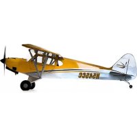
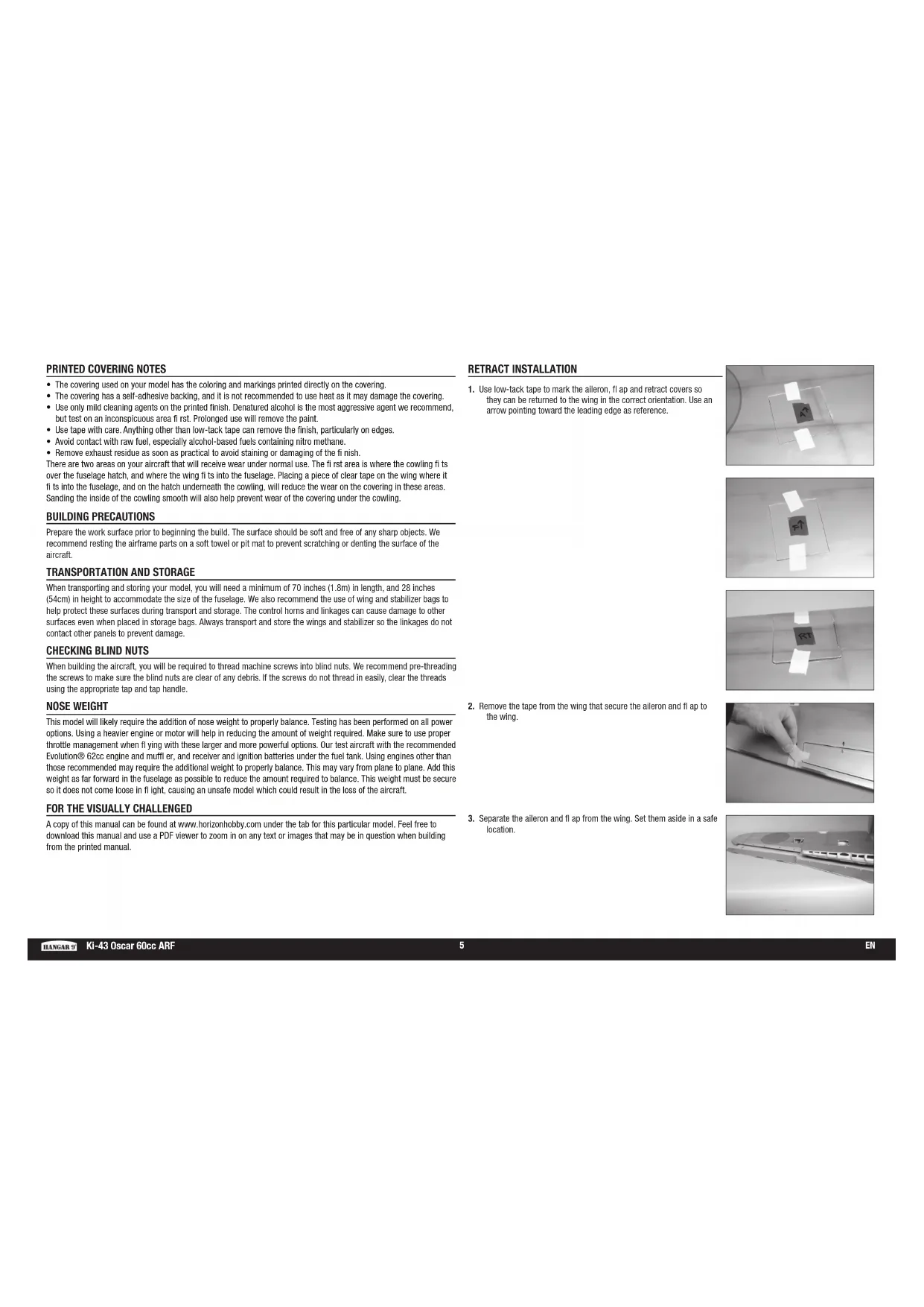
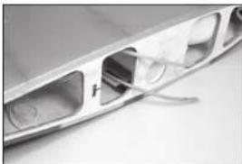
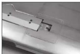
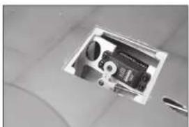
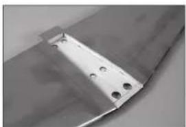
RETRACT INSTALLATION
-
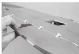
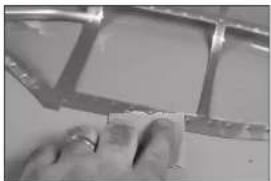
Use low-tack tape to mark the aileron, flap and retract covers so they can be returned to the wing in the correct orientation. Use an arrow pointing toward the leading edge as reference.
-
Remove the tape from the wing that secure the aileron and fl ap to the wing.
-
Separate the alleron and flap from the wing. Set them aside in a safe location.
natural_image
Interior ceiling view with two white rectangular panels and a central dark square, no visible text or symbols
natural_image
Abstract geometric composition with a central dark square and scattered white squares, no text or symbols present.
natural_image
Close-up of a ceiling-mounted electrical socket with a black square component and white tape (no visible text or symbols)
natural_image
Close-up of a hand holding a white object with a small black dot and arrow, on a surface (no text or symbols visible)
natural_image
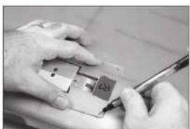
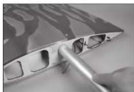
Close-up of a silver electronic device with a curved top and internal components (no visible text or symbols)- Use a hobby knife and #11 blade to remove the covering from the retract openings in the wing. Trim the covering inside the opening.
natural_image
Close-up of a metallic kitchen appliance with a bowl and handle (no visible text or symbols)- Both air lines can be retrieved at the fl ap servo opening. Use a piece of low-tack tape to secure the lines together so they don't fall back into the wing.
natural_image
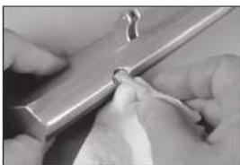
Close-up of a metallic electronic component with a small rectangular cutout and wiring (no visible text or symbols)- Use low-tack tape to secure a piece of cardboard over the wing. This will provide a place to rest the retract when routing the air lines and prevent damage to the underside of the wing.
natural_image
Interior view of a stainless steel kitchen appliance with visible door, sink, and handle (no text or symbols)- Fit the retract in the wing. Trim as necessary to provide clearance.
natural_image
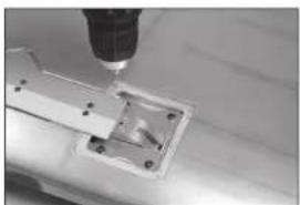
Interior view of a mechanical assembly or enclosure with no visible text or symbols- Use a pin vise and 1/8-inch (3mm) drill bit to make a hole in the retract well for the air line.
natural_image
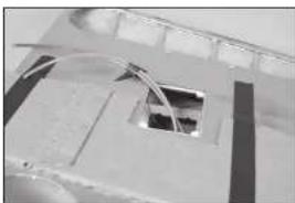
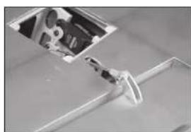
Close-up of a metallic mechanical component with internal cavities and mounting holes (no visible text or symbols)- The air lines can now be retrieved at the wing root.
natural_image
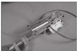
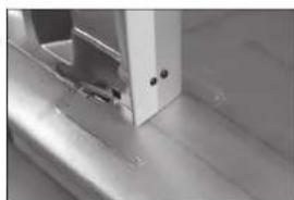
Close-up of a metallic mechanical component with visible internal cutouts and a small inset showing a circular feature (no text or symbols)- Cut a 19-inch (482mm) piece of the orange and blue air line. Attach each air line to the retract. Using different colors makes connecting the retracts correctly much easier when assembling the model.
natural_image
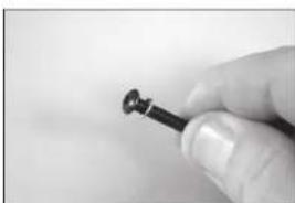
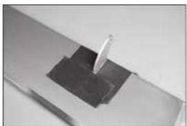
Close-up of a mechanical or electronic device with metallic components and wires (no visible text or symbols)- Place a lock washer on the M4 x 25 button head cap screw. Prepare four screws at this time.
natural_image
Close-up of a hand holding a small black nail (no text or symbols visible)→ Use a heat gun on low to soften the air lines slightly so they will slide on the fittings. → Make sure to orient the air line colors the same on both the left and right retracts so they operate in the same manner.
- Route the air lines into the wing.
natural_image
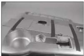
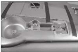
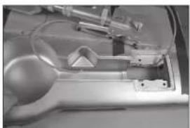
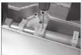
Interior view of a mechanical device with visible components and wiring (no text or symbols)- Use the M4 x 25 button head cap screws to secure the retract in the wing. Place a drop of threadlock on each of the screws before their installation. Tighten the screws using a 2.5mm hex wrench.
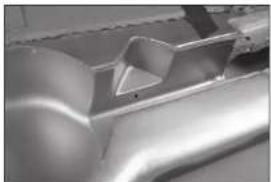
→ The cardboard can be removed from the wing after the retract has been secured.
It may be necessary to use spacers under the retract frame to make sure there is no torsional stress when tightened into position. Torsional stress can cause intermittent operation of the retract unit.
natural_image
Close-up of a mechanical assembly with a metallic component and mounting holes (no visible text or symbols)- Place a drop of light machine oil on the M6 x 55 socket head cap screw that will function as the wheel axle.
natural_image
Close-up of a metallic tool or bracket on a flat surface (no visible text or symbols)- Use an M3 x 5 setscrew and 1.5mm hex wrench to secure the position of the gear door mount.
Do not over tighten the screws or use threadlock as it will damage the composite material of the mounts.
natural_image
Close-up of a mechanical component with a precision tool inserted, showing internal structure and mounting holes (no visible text or symbols)- Slide the M6 x 55 socket head cap screw through the wheel. Make sure the wheel spins freely on the screw.
natural_image
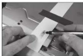
Close-up of a hand holding a dark circular object with a central hole, no visible text or symbols.- Tape a piece of paper to the wing that will go over the upper mount. Rub a pencil on the paper to reveal the locations for the mounting holes.
natural_image
Close-up of a mechanical assembly with a white sheet and metal components (no visible text or symbols)- Thread the screw into the retract. Tighten the screw enough that the wheel can spin freely, yet there isn't any excess movement of the wheel on the screw. Once set, use an M3 x 5 setscrew and 2mm hex wrench to tighten the setscrew. Use a drop of threadlock on both the M6 x 55 socket head cap screw and M3 x 5 setscrew to prevent them from vibrating loose.
natural_image
Close-up of a mechanical component with a metallic tool inserted, showing a circular ring and a flat blade (no text or symbols visible)- Use a drill and 1/8-inch (3mm) drill bit to drill the holes for the lower gear mounting holes in the gear door.
natural_image
Close-up of a metallic tool inserted into a white rectangular block with a small hole, no visible text or symbols.- Position the gear door mount near the wheel as close to the wheel as possible. The fl at area will align with the bottom of the wing. Use an M3 x 5 setscrew and 1.5mm hex wrench to secure the position of the gear door mount.
natural_image
Close-up of a mechanical assembly with metal components and a tool (no visible text or symbols)- Attach the gear door to the mount using two M3 x 12 button head screws and a 2mm hex wrench.
→ Check the positioning of the door to make sure it is centered in the opening and aligns with the opening near the wheel.
Do not over tighten the screws or use threadlock as it will damage the composite material of the mounts.
natural_image
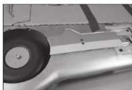
Close-up of a car wheel assembly with visible components (no text or symbols)- Position the upper mount 2 3' inches (70mm) from the lower mount.
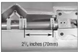
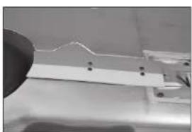
- Use a felt-tipped pen to mark the location for the upper gear door mounting screws on the gear door.
natural_image
Close-up of hands using a tool to adjust or install a white sheet on a mechanical component (no visible text or symbols)- Remove the cover and use a drill and 1/8-inch (3mm) drill bit to drill the two holes for the upper gear door mounting screws. The door can now be attached to the mounts using the four M3 x 12 button head screws and 2mm hex wrench.
natural_image
Close-up of a mechanical component with a circular feature and mounting holes (no visible text or symbols)- Thread an M2 x 10 sheet metal screw into each hole using a #1 Phillips screwdriver. Remove the screws before proceeding.
natural_image
Close-up of a mechanical assembly with metal components and a vertical rod (no visible text or symbols)- If the gear door is not fl ush with the bottom of the wing, the mounts may need to be adjusted. The mounting area for the lower mount can also be sanded using medium grit sandpaper to make any adjustments to the gear door alignment.
natural_image
Close-up of a metallic mechanical part with a small inset showing a small component, partially held by a hand (no visible text or symbols)- Apply a small amount of thin CA to harden the threads made in the previous step. Allow the CA to fully cure before installing the retract cover.
natural_image
Close-up of a mechanical component with a white fluid jet or pipe inserted, showing no visible text or symbols.- Use a hobby knife or other sharp tool to puncture the covering at the screw holes that will secure the cover to the wing. Also remove the covering to clear the retract mechanism.
natural_image
Close-up of a hand holding a small white plastic component with a dark square patch, against a plain background (no text or symbols visible)- Secure the retract cover to the wing using four M2 x 10 sheet metal screws. Use a #1 Phillips screwdriver to tighten the screws.
natural_image
Close-up of a metallic mechanical component with mounting holes and internal structure (no visible text or symbols)- Place the cover into position. Use a felt-tipped pen to mark the locations for the mounting screws
natural_image
Close-up of hands assembling electronic components with a pen (no visible text or symbols)- Check that the retract can be fully extended without the gear door hitting the cover. Trim the gear door as necessary if it hits the cover.
natural_image
Close-up of a metallic mechanical component with mounting holes and a flat surface (no visible text or symbols)- Use a pin vise and 1/16-inch (1.5mm) drill bit to drill the mounts for the retract covers.
natural_image
Close-up of a precision tool tiping a mechanical component (no visible text or symbols)There will be movement in the gear during their operation so make sure there is a gap between the gear door and wing so they do not contact each other during the operation of the gear.
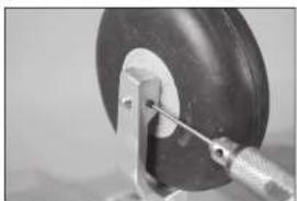
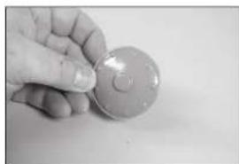
- Use hobby scissors and medium grit sandpaper to prepare the hub caps for installation.
The hub caps can be painted if desired. Be sure to fully scuff and prepare the surface. Applying paint directly to the hub cap with no preparation will result in flaking paint. Always test paint on a piece of scrap material to check its compatibility to the plastic.
natural_image
Hand holding a circular object with a small mark, possibly a button or knob (no text or symbols visible)- Use contact adhesive to glue the hub cap to the wheel. Use low-tack tape to hold the hub cap in position until the adhesive fully cures.
→ Repeat this section to install the remaining retract assembly.
natural_image
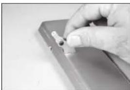
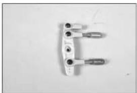
Close-up of a circular mechanical component with a central hole (no visible text or symbols)AILERON INSTALLATION
- Use medium-grit sandpaper to lightly sand the control horn where it fits into the control surface. Clean the sanded area using a paper towel and isopropyl alcohol to remove any debris or oils. This provides the surface texture necessary for the epoxy to bond to.
→ Use tape on the painted area to help prevent removing the exposed portion of the control horn. Remove the tape once the control horn has been sanded.
- Insert the M3 x 10 button head screw into the hole in the control horn. Remove any paint using a hobby knife and #11 blade so the screw fl ts into the hole easily. Check all the control horns.
→ The hole should be just large enough for the screw to slide through, yet still fit snugly in the hole and not move excessively.
-
Run your fl nger along the bottom of the alleron to locate the area for the control horn. Use a hobby knife and #11 blade to remove the covering, exposing the slots for the control horn.
-
Test fit the control horn in the slot. Do not force the control horn into the slot. Use a square to make sure the control horn is square to the control surface. Do not force the control horn in the slot.
If the control horn fits tight, or is not square, use a rotary tool 3/32-inch (2.5mm) drill bit to carefully enlarge and reshape the hole. Wrap a piece of low-tack tape around the drill bit to set the depth of the drill bit so it won't accidentally pass through the opposite side of the control surface.
natural_image
Close-up of a hand holding a small metallic object with a white tip, possibly part of a device or tool (no visible text or symbols)
natural_image
Close-up of a hand holding a small object, possibly a tool or device, against a plain background (no text or symbols visible)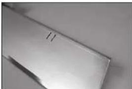
natural_image
Close-up of a metallic surface with a small mark and diagonal line (no text or symbols visible)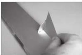
natural_image
Close-up of a hand holding a knife, showing a curved blade (no text or symbols visible)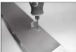
natural_image
Close-up of a precision tool tip interacting with a metallic surface (no visible text or symbols)- Place tape around the slot in the aileron for the aileron control horn.
natural_image
Close-up of a metallic mechanical component with a small protrusion on top (no visible text or symbols)- Once the epoxy has fully cured, pull on the control horn to make sure it is glued securely in the aileron. If not, remove the control horn and sand off any adhesives. Repeat this section to glue the control horn in the aileron.
natural_image
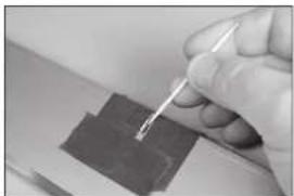
Close-up of a hand holding a small object on a surface (no visible text or symbols)- Remove the control horns from the control surfaces. Apply epoxy to the slot in the alleron. Make sure the epoxy gets into the slot for a good bond between the surfaces and control horn.
natural_image
Close-up of a hand holding a pen over a dark rectangular object (no visible text or symbols)- Apply epoxy to the area of the control horn that fl is into the slot. Use enough epoxy so the control horn will be fully bonded to the control surfaces.
natural_image
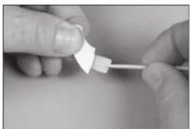
Close-up of hands holding a small white plastic object with a string (no text or symbols visible)- Before the epoxy fully cures, remove the tape from around the control horn. This will allow the epoxy to flow around the control horn, creating a small fi let between the control horn and surface for a fi nished look and secure bond. Allow the epoxy to fully cure before proceeding.
natural_image
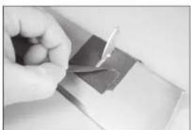
Close-up of a hand holding a small metallic object with a tool, possibly a component or tool, on a plain surface (no visible text or symbols)- Test fl t the remaining control horn. When gluing the control horn, place the ball end between the horns and insert the M3 x 10 button head screw through the control horns and rod ends. This will align the horns correctly, making the linkage installation easier later.
natural_image
Close-up of a metallic object with a curved handle, possibly a tool or bracket, against a plain background (no text or symbols visible)→ Do not mix any epoxy until instructed to do so.
→ Use the short hinges for the ailerons. The longer hinges are used for the flaps due to the hinging technique used.
-
Apply a small amount of oil to the fl ex point of the hinge to prevent epoxy from entering the hinge.
-
Insert the hinge so the center of the hinge point aligns with the front edge of the bevel on the control surface. Check that the hinge can move freely.
-
Position the hinge so it is perpendicular to the hinge line when fully deflected.
-
Mix 1/2 ounces (15mL) of 30-minute epoxy. Remove the hinges, then use a toothpick to apply epoxy inside each of the holes for the hinges.
-
Apply epoxy to the outside of the hinge using a toothpick
natural_image
Close-up of a hand holding a small wire with a small hole, no visible text or symbols
natural_image
Close-up of a white plastic tool with a metallic clip, no visible text or symbols
natural_image
Close-up of a hand holding a metallic cylindrical object with two small protrusions (no visible text or symbols)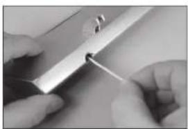
natural_image
Close-up of hands using a tool to apply material or tools on a surface (no visible text or symbols)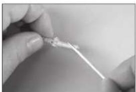
natural_image
Close-up of hands holding a thin, thin wire or filament against a plain background (no text or symbols visible)-
Insert the hinges into the control surface. Verify the hinge position is correct. Use a paper towel and isopropyl alcohol to remove any excess epoxy. Allow the epoxy to fully cure before proceeding.
-
Mix 1/2 ounces (15mL) of 30-minute epoxy. Use a toothpick to apply epoxy inside each of the holes for the hinges.
-
Apply epoxy to the outside of the hinge using a toothpick
-
Fit the aileron to the wing. Check that the aileron can move freely, and the hinges are all aligned properly.
-
Use a paper towel and Isopropyl alcohol to remove any excess epoxy. Use low-tack tape to hold the aileron in position until the epoxy fully cures.
natural_image
Close-up of hands holding a metal tool with a small ring (no visible text or symbols)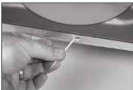
natural_image
Close-up of a hand holding a small tool near a curved surface (no visible text or symbols)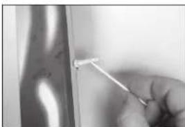
natural_image
Close-up of a hand holding a small metal object with a pointed tip, against a blurred background (no text or symbols visible)
natural_image
Close-up of a textured surface with a circular hole, possibly a material sample or pattern (no text or symbols visible)
natural_image
Close-up of a hand holding a tool over a metallic surface (no visible text or symbols)- Once the epoxy has fully cured, pull on the wing and aileron to make sure the hinges are glued securely. If not, remove the aileron and sand off any adhesives. Repeat this section to glue the hinges.
natural_image
Close-up of hands holding a circular object with a grid pattern, possibly part of a technical or mechanical component (no visible text or symbols)AILERON SERVO INSTALLATION
- Use a hobby knife and #11 blade to remove the covering for the aileron pushrod exit.
- Center the aileron servo. Attach the servo horn on the servo perpendicular to the servo centerline.
- When attaching the linkage to the alleron servo arm, use the hole in the arm that is 5/8-inch (16mm) from the center of the arm.
- Prepare both the left and right aileron servos at this time.
- Assemble the linkage for the alleron using two ball ends and the 3^15/16 inch (100mm) threaded rod. Thread each ball end 12 turns on the link. Adjust the length so the distance between the ball ends measures 3^5/32 inches (80mm).
natural_image
Close-up of a hand using tweezers to apply a mechanical component (no visible text or symbols)
natural_image
Close-up of a hand holding a small black mechanical component with a white clip, attached to a wire (no visible text or symbols)
natural_image
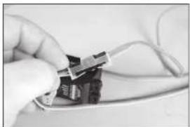
Two black plastic connectors with white connectors and wires, no visible text or symbols
- Secure the servo ball link to the servo arm using an M3 x 10 button head screw, M3 washer and M3 lock nut. Use a 2.5mm hex wrench and 5.5mm nut driver to tighten the hardware.
natural_image
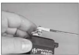
Close-up of a hand holding a small electronic device with a white cable, no visible text or symbols on the device itself.- Secure a 6-inch (150mm) servo extension to the servo using a commercially available retainer (SPMA3054).
→ The length of the extension may vary depending on servo selection. The extension listed works with the recommended servos.
natural_image
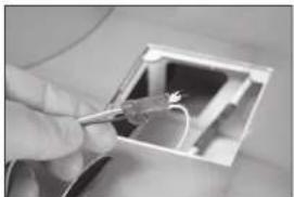
Close-up of a hand inserting a small electronic component into a device (no visible text or symbols)- Tie or tape the string located inside the wing to the end of the servo lead.
natural_image
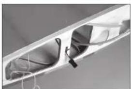
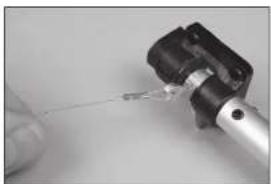
Close-up of hands holding a wire inside an open electrical socket (no visible text or symbols)- Use the string to pull the servo lead through the wing and out at the root.
→ We left a small amount of the string on the aileron servo lead so it can be quickly differentiated between the flap servo lead that will be installed later.
natural_image
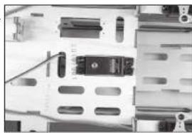
Close-up of a metallic mechanical component with internal cavities and a strap (no visible text or symbols)- Install the alleron servo in the wing with the output facing the leading edge. Make sure to prepare the servo mounting holes by threading a servo mounting screw into each hole and removing them. Harden the mounting screw locations with thin CA before installing the servo.
natural_image
Interior view of a small electronic device with visible internal components and wiring (no text or symbols)- Secure the servo ball link to the control horn using an M3 x 10 button head screw, M3 washer and M3 lock nut. Use a 2.5mm hex wrench and 5.5mm nut driver to tighten the hardware.
→ Connect the servo to the radio system to hold the aileron servo in the centered position. Disconnect the ball from the control horn and adjust the linkage so the aileron is in the neutral position. Reinstall the hardware once the linkage has been adjusted.
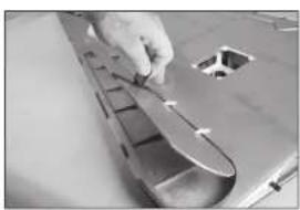
- Use the steps outlined for the retract cover to install the aileron cover.
natural_image
Close-up of a mechanical component with internal parts, possibly an optical or electrical assembly (no visible text or symbols)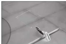
natural_image
Close-up of a white mechanical component attached to a grid-patterned surface (no visible text or symbols)HINGING THE FLAPS
The flaps must be positioned to the wing before the epoxy begins to cure. Make sure to read through all the steps before mixing any epoxy. Glue only one flap at a time to allow enough working time to properly install the hinges.
- Locate the flap control horns. When installed, the concave portion of the horn (as indicated in the drawing) will face toward the top of the fl aps.
- Run your finger down the leading edge of the fl ap to locate the area for the fl ap control horns. Use a hobby knife and #11 blade to remove the covering, exposing the slots for the control horn. Use 15-minute epoxy to glue the fl ap control horns in position. Remove any excess epoxy using a paper towel and isopropyl alcohol.
→ Use the steps outlined for the aileron control horns to install the flap control horns. Make sure to check that the flap control horns are glued securely in the flaps once the adhesive fully cures. - Wrap a piece of low-tack tape around the fl ap to create a tab so the fl ap can be lifted and lowered into position when fl tting the hinges.
natural_image
Simple line drawing of a fish head with an arrow pointing to it (no text or symbols)
natural_image
Close-up of a metallic object with a triangular tip and circular hole, possibly part of a mechanical or architectural component (no text or symbols visible)
natural_image
Close-up of a metallic mechanical component with a clamping mechanism (no text or symbols visible)→ Use the long hinges when installing the flaps to the wing.
- Test fit the hinges to the flap. Do not use any adhesives now. Slide the hinge into position. Position as shown, checking to make sure it can move freely.
- Check the fl t of the fl ap to the wing. It will fl t centered in the opening. The hinge pin will be positioned directly over the gap between the leading edge of the fl ap and the aft edge of the wing opening. Test the operation of the fl ap to make sure the hinges are properly aligned and the fl ap movies freely.
natural_image
Close-up of a hand holding a metal object with a small protrusion (no visible text or symbols)
natural_image
Close-up of a metallic panel with visible internal components and wiring (no text or symbols)- The flap will also align to the bottom of the wing when the hinges are positioned correctly.
→ Use 15-minute or 30-minute epoxy to allow enough working time during the hinge installation. - Remove the fl ap from the wing and remove the hinges. Apply epoxy into each of the holes in the fl ap.
Do not use an excessive amount of epoxy when gluing the hinges. Use enough epoxy to securely adhere the hinges to the surfaces. - Apply epoxy to each hinge where it will be inserted into the flap. Insert the hinges in the flap.
- Apply epoxy to each hinge where it will be inserted into the wing.
- Apply epoxy into each of the holes in the wing.
natural_image
Close-up of a hand holding a small object with white triangular elements, possibly part of a mechanical or architectural component (no visible text or symbols)
natural_image
Close-up of a hand holding a small metallic tool over a flat surface (no text or symbols visible)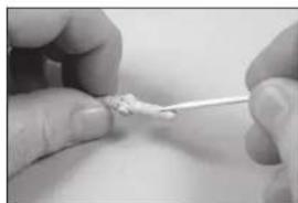
natural_image
Close-up of hands using a pipette to apply a small object (no visible text or symbols)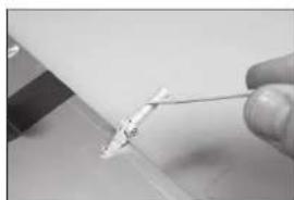
natural_image
Close-up of a hand holding a pen tip, no visible text or symbols
natural_image
Close-up of a hand holding a small electronic component with a screwdriver inserted (no visible text or symbols)- Fit the fl ap to the wing. Check that the fl ap can move freely, and the hinges are all aligned properly. Use low-tack tape to hold the fl ap in position until the epoxy fully cures.
natural_image
Close-up of a hand using a tool to cut or inspect a component on a metal tray (no visible text or symbols)- Use a paper towel and isopropyl alcohol to remove any excess epoxy before it can fully cure. Use care not to get epoxy in the moving part of the hinge or between the fl ap and wing. Continue once the epoxy has fully cured for both sets of fl ap hinges.
→ Make sure to check that the flap hinges are glued securely once the adhesive has fully cured.
→ Repeat this section for the remaining flap hinge installation.
natural_image
Close-up of a hand holding a small white object on a surface, with no visible text or symbols.FLAP SERVO INSTALLATION
- Center the fl ap servo. Attach the servo horn on the servo perpendicular to the servo centerline.
→ We recommend setting the throws to 0% for radios using a three-position switch to prevent damaging the servo if the linkage is not the correct length.
-
When attaching the linkage to the aileron servo arm, use the hole in the arm that is 5/8-inch (16mm) from the center of the arm.
-
Prepare both the left and right flap servos at this time.
-
Assemble the linkage for the fl ap using two ball ends and the 4^23/12 inch (120mm) threaded rod. Thread each ball end 12 turns on the link. Adjust the length so the distance between the ball ends measures 4^/4 inches (108mm).
-
Remove the servo arm from the servo. Secure the servo ball link to the servo arm using an M3 x 10 button head screw, M3 washer and M3 lock nut. Use a 2.5mm hex wrench and 5.5mm nut driver to tighten the hardware.
natural_image
Close-up of a hand holding a small electronic component with a white handle, against a plain background (no text or symbols visible)
natural_image
Two black mechanical components with metallic fittings and wires, placed on a plain white surface (no text or symbols visible)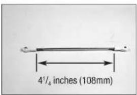
natural_image
Close-up of a small mechanical component with a metallic shaft and connector (no visible text or symbols)- The ball link will be attached to the underside of the servo arm as shown.
natural_image
Close-up of a white mechanical component with a cylindrical end and a threaded shaft (no text or symbols visible)- Move the servo to the UP fl ap position using the radio system. Adjust the throws at the radio system to bring the fl ap in alignment with the bottom of the wing.
natural_image
Interior view of an open electrical enclosure with visible internal components (no text or symbols)- Install the fl ap servo in the wing with the output facing the leading edge. Make sure to prepare the servo mounting holes by threading a servo mounting screw into each hole and removing them. Harden the mounting screw locations with thin CA before installing the servo.
natural_image
Interior view of an open electrical enclosure with a small device inside (no visible text or symbols)- Move the servo to the FULL flap position of 1^31/32-2^3/5 inches (50–60mm) using the radio system. Adjust the throws in the radio system to obtain the measurements listed.
natural_image
Exterior view of a metallic electronic component with internal traces and mounting holes (no visible text or symbols)→ The flap servos can be positioned in the wing to allow the use of a Y-harness to connect the servos to the receiver.
- Secure the servo ball link to the control horn using an M3 x 10 button head screw, M3 washer and M3 lock nut. Use a 2.5mm hex wrench and 5.5mm nut driver to tighten the hardware.
natural_image
Close-up of a mechanical component with a central knob and flanges (no visible text or symbols)
natural_image
Interior view of a room with a framed picture showing internal mechanical components (no visible text or symbols)- Attach the servo arm to the servo.
natural_image
Interior view of a mechanical device with no visible text or symbols- The linkage may rub against the wing structure depending on servo selection. Use a hobby knife with a #11 blade or a rotary tool and sanding drum to trim the wing structure as necessary to clear the linkage.

natural_image
Metallic boat hull on a flat surface, no visible text or symbols- Adjust the length of the linkage to position the fl ap in the mid fl ap position of 1-1116 inches (25–30mm).
→ Remember to set the throws to 0% in both the up and down positions to prevent damage to the servo, flap or linkage.
natural_image
Metallic electronic component with curved and rectangular features, no visible text or symbols
natural_image
Close-up of a white train or high-speed train with multiple windows and side compartments (no visible text or symbols)- Use the steps outlined for the retract cover to install the flap cover.
→ Repeat this section for the remaining flap servo installation.
natural_image
Close-up of a transparent plastic sheet with visible internal markings and a circular object on top (no text or symbols)DROP TANK INSTALLATION
- Run your fi inger along the bottom of the wing to locate the blind nuts for the drop tank mount. Use a hobby knife and #11 blade to remove the covering, exposing the blind nuts.
Thread a screw into the blind nuts by hand first to make sure the threads are clear. Cross threading, stripping, or damaging the blind nuts within the wing will require considerable work to rectify.

- Thread the drop tank mounts into the blind nuts in the pylons. Do not over-tighten the mounts and damage the pylon.
natural_image
Metal mechanical bracket with two side slots and a flat top (no text or symbols visible)- Attach the pylon to the wing using two M4 x 15 socket head cap screws and two M4 lock washers. Use a 3mm hex wrench to tighten the screws.
→ Place a drop of canopy glue on each screw before their installation. This will keep them from vibrating loose yet leave them easily removable.

natural_image
Exterior view of a modern office building (no signage)- Attach the drop tank to the mounts using four M3 x 12 button head screws. Use a 2mm hex wrench to tighten the screws.
→ Place a drop of canopy glue on each screw before their installation. This will keep them from vibrating loose yet leave them easily removable.
→ Repeat this section for the remaining tank installation.

natural_image
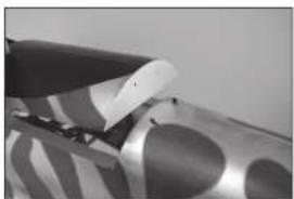
Exterior view of a modern office building (no signage)STABILIZER INSTALLATION
- Remove the tape and packing materials from the fuselage.
natural_image
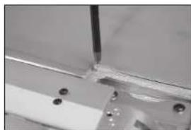
Close-up of a gloved hand holding a small object over a patterned surface (no text or symbols visible)- Run your fi nger along the sides of the fuselage to locate the opening for the stabilizer. Use a hobby knife and #11 blade to remove the covering from the fuselage.
natural_image
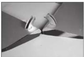
Close-up of a jet aircraft in flight, showing blade and fuselage details (no visible text or symbols)
natural_image
Close-up of hands holding a transparent plastic bag over a patterned fabric (no visible text or symbols)- Use a razor saw to remove the section of the tail post from the stabilizer slot.
The tail post is left in position at the factory to prevent damage and maintain the structural integrity of the fuselage during shipping and must be removed to install the stabilizer.

natural_image
Close-up of a metallic mechanical component with a tool inserted, no visible text or symbols- Move the canopy latch toward the front of the fuselage. Lift the canopy hatch from the fuselage at the rear and remove it from the fuselage. Set it aside in a safe location.
natural_image
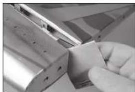
Close-up of a metallic object with a pointed tip and circular patterns, possibly part of a mechanical or electronic component (no visible text or symbols)- Use medium grit sandpaper to sand the fuselage smooth with the stabilizer slot.
natural_image
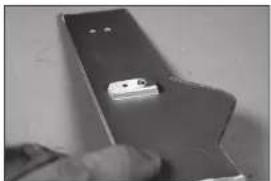
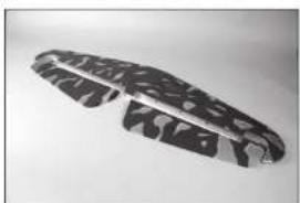
Close-up of a hand holding a small metallic object, possibly a tool or component, with no visible text or symbols.- Separate the elevators from the stabilizer.
natural_image
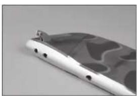
Close-up of a textured, dark metallic object with no visible text or symbols- Run your finger along the top of the wing to locate the blind nut for the wing retaining bolt. Use a hobby knife with a #11 blade to remove the covering from the wing to expose the blind nut for the wing retaining bolt.
For additional security, glue can be applied to the blind nut on the inside of the wing. Epoxy with micro balloons to thicken it works well for this task. Make sure not to get any adhesive inside the threads of the blind nut.
natural_image
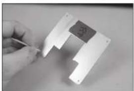
Close-up of a mechanical component with a tool tip and circular features (no visible text or symbols)- Run your finger along the bottom of the stabilizer to locate the center. Use a hobby knife and #11 blade to remove the covering from the center section.
natural_image
Close-up of a metallic mechanical component with four circular holes (no text or symbols visible)- Slide the wing tube into the wing tube socket.
The wing tube may be a tight fit in the socket. Polishing the wing tube with fine sand paper or steel wool will help ease the installation of the wing tube. Do not force the wing tube in the socket as it can damage the structure inside the wing.
natural_image
Close-up of a hand holding a metallic object with a curved panel and a small inset showing a camera lens (no text or symbols visible)- Slide the wing panel into position. Guide the flap and aileron leads, as well as the retract air lines, into the fuselage.
natural_image
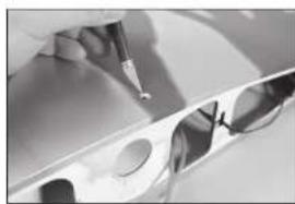
Close-up of a rolled-up fabric with abstract wavy patterns on the surface (no text or symbols visible)- Use a felt-tipped pen to transfer the fuselage outline onto the top of the stabilizer.
natural_image
Close-up of a hand holding a pen, writing on paper with blurred background (no visible text or symbols)- Secure the wing to the fuselage using the 1/4-20 x 1 nylon wing bolt.
→ Repeat the steps to secure the remaining wing panel on the fuselage.
natural_image
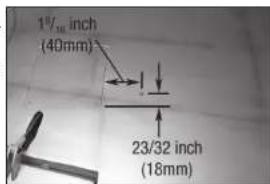
Architectural floor plan showing room layouts and structural elements (no text or labels visible)- Use a ruler and a hobby knife with a #11 blade to carefully cut the covering 1/8 inch (3 mm) inside the line drawn on the top of the stabilizer to remove the covering from the center of the stabilizer. Use care not to cut into the underlying wood, weakening the stabilizer.
natural_image
Close-up of a hand holding a small white object on a dark surface, with no visible text or symbols.- Place the stabilizer in position. Use a straight edge to align the rear of the stabilizer and fin.
natural_image
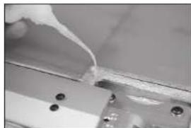
Close-up of a hand holding a ruler measuring a quantity (no visible text or symbols)- Mix 3/4 ounce (25ml) of 30-minute epoxy. Use an epoxy brush to apply epoxy to the exposed wood on the top of the stabilizer.
natural_image
Close-up of a tool applying material to a white strip on a dark surface (no visible text or symbols)- Stand back 8-10 feet (2-3 meters) and check that the stabilizer is aligned with the wing. Lightly sand the stabilizer saddle on the fuselage to correct any misalignment.
- Use an epoxy brush to apply epoxy to the exposed wood on the bottom of the stabilizer as well.
natural_image
Close-up of a metal bracket with a tool applying material to a surface (no visible text or symbols)- Measure from each wing tip to each stabilizer tip. Adjust the stabilizer so the measurements are the same for both sides.
- Use an epoxy brush to apply epoxy to the stabilizer mounting surface for the stabilizer. Position the stabilizer back on the fuselage and check its alignment. Use a paper towel and a small amount of isopropyl alcohol to remove any excess epoxy from the fuselage and stabilizer before the epoxy fully cures. Allow the epoxy to fully cure before proceeding.
→ Check the position of the stabilizer repeatedly during the curing process to make sure it has not moved.
natural_image
Close-up of a hand holding a pen, with blurred background (no visible text or symbols)ELEVATOR INSTALLATION
- Install the elevator control horns. Their installation is the same as the aileron control horns.
→ Make sure to check that the control homs are securely glued before proceeding.
-
Glue the hinges in the elevator using 30-minute epoxy. The Installation of the elevator hinges is similar to the aileron hinges. Use the short hinges to hinge the elevators
-
Glue the hinges to the stabilizer using 30-minute epoxy.
→ Make sure to check that the elevator hinges are glued securely once the adhesive has fully cured.
-
Prepare the holes in the fuselage for the elevator servo by threading a screw into each hole. Remove the screws and place 2 to 3 drops of thin CA in each hole to harden the surrounding wood. Once the CA has fully cured, install the elevator servo with the servo output shaft toward the front of the fuselage.
-
Slide a 36 58 inch (930mm) pushrod into the pushrod tube.
natural_image
Close-up of metallic mechanical components or clamps on a flat surface (no visible text or symbols)
natural_image
Close-up of a metallic support structure with multiple metal pins, mounted on a flat surface (no text or symbols visible)
natural_image
Close-up of a metallic object with embossed text, possibly a shoe or part (no readable text or symbols)
natural_image
Close-up of a mechanical assembly with a central component (no visible text or symbols)
natural_image
Interior architectural rendering of a modern building with curved structural elements (no visible text or symbols)-
Use a hobby knife with a #11 blade to trim the covering so the pushrod can exit the fuselage.
-
Thread a ball end 12 turns on the pushrod. Secure the servo ball link to the control horn using an M3 x 10 button head screw, M3 washer and M3 lock nut. Use a 2.5mm hex wrench and 5.5mm nut driver to tighten the hardware.
-
Center the elevator servo using the radio system. Attach the servo horn on the servo perpendicular to the pushrod. Thread a ball end 12 tums on the pushrod. Secure the servo ball link to the control horn using an M3 x 10 button head screw, M3 washer and M3 lock nut. Use a 2.5mm hex wrench and 5.5mm nut driver to tighten the hardware.
-
Repeat the previous steps to install the remaining elevator servo and pushrod.
natural_image
Abstract grayscale image with vertical striped patterns and layered textures (no text or symbols)
natural_image
Close-up of a mechanical component with a ruler and roller, no visible text or symbols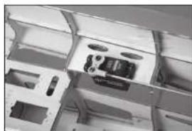
natural_image
Interior view of a transparent filing cabinet with internal compartments and ventilation slots (no visible text or symbols)
natural_image
Close-up of a mechanical component with a central metallic bracket and mounting holes (no visible text or symbols)
natural_image
Close-up of a metallic mechanical component with a curved edge and flange (no visible text or symbols)RUDDER INSTALLATION
- Install the rudder control horns. Their installation is the same as the aileron control horns. Make sure to install the rudder control horns on the correct side of the rudder.
→ Make sure to check that the rudder control horns are glued securely once the adhesive has fully cured.
-
Glue the hinges in the rudder using 30-minute epoxy. The installation of the rudder hinges is similar to the alleron hinges.
-
Glue the hinges to the fin using 30-minute epoxy.
→ Make sure to check that the rudder hinges are glued securely once the adhesive has fully cured.
natural_image
Close-up of a flat electronic device with metallic contacts and a patterned cover (no visible text or symbols)
natural_image
Curved metallic object with abstract wavy patterns, mounted on a flat surface (no text or symbols visible)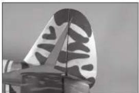
natural_image
Close-up of a butterfly wing with black and white patterned design (no text or symbols visible)RUDDER LINKAGE INSTALLATION
-
Prepare the holes in the fuselage for the rudder servo by threading a screw into each hole. Remove the screws and place 2 to 3 drops of thin CA in each hole to harden the surrounding wood. Once the CA has fully cured, install the rudder servo with the servo shaft toward the front of the fuselage.
-
Slide a 40 16 inch (1020mm) pushrod into the rudder pushrod tube.
-
Thread a ball end 12 turns on the pushrod. Secure the servo ball link to the control horn using an M3 x 10 button head screw, M3 washer and M3 lock nut. Use a 2.5mm hex wrench and 5.5mm nut driver to tighten the hardware.
-
Center the rudder servo using the radio system. Place the servo arm on the servo so it is perpendicular to the servo centerline. It may be necessary to rotate the arm 180-degrees to achieve a better alignment of the arm on the servo. Mark the arm so it can be returned to its position on the servo.
-
Thread a ball end 12 turns on a cable fl tting. Prepare two cable fi ttings at this time.
natural_image
Close-up of a computer motherboard with visible circuitry and connectors (no readable text or symbols)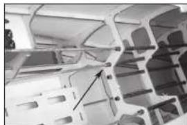
natural_image
Close-up of a mechanical component with internal cavities and mounting holes (no visible text or symbols)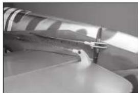
natural_image
Close-up of a jet engine component with visible cutting edge and mounting bracket (no text or symbols)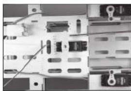
natural_image
Close-up of a computer motherboard with visible circuit breakers and connectors (no text or symbols)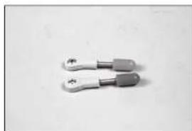
natural_image
Two metallic tool holders with handles, no visible text or symbols-
Attach a ball end, and the two ball ends with cable fittings, to the rudder servo arm. Use three M3 x 10 button head screws, three M3 washers and three M3 lock nuts. Use a 2.5mm hex wrench and 5.5mm nut driver to tighten the hardware.
-
Thread the pushrod into the ball end on the servo arm. With the radio system on, adjust the linkage so the rudder is centered when the arm is on the servo. Do not install the servo arm screw at this time.
natural_image
Close-up of a mechanical clamp or bracket component (no visible text or symbols)
natural_image
Close-up of an electronic circuit board with visible components and wiring (no text or symbols)TAIL WHEEL INSTALLATION
- Use hobby scissors to trim the tail gear fairing.
→ The installation of the tail gear fairing is optional.
-
Place medium grit sandpaper against the fuselage. Lightly sand the tall gear fairing to match the shape of the fuselage.
-
Slide the latch toward the rear of the fuselage and remove the tail gear cover. Set the cover aside.
-
Slide a sleeve on one end of the cable.
-
Pass the cable through the hole in the tail wheel arm. Pass the cable back through the sleeve.
natural_image
Hand holding a small black object with a white circular hole, against a plain background (no text or symbols visible)
natural_image
Close-up of hands holding a small black object with a dark square, possibly part of a device or tool (no visible text or symbols)
natural_image
Close-up of a hand holding a striped fabric with a smiley face pattern (no text or symbols visible)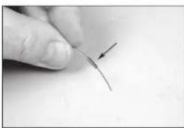
natural_image
Close-up of a finger pointing to a thin, curved wire or filament (no text or symbols visible)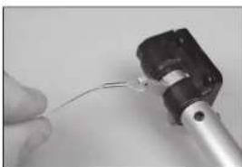
natural_image
Close-up of a hand holding a thin wire with a metallic component (no visible text or symbols)- Use crimping pliers to secure the sleeve to the cable.
→ Use caution to not apply excessive pressure and cut the sleeve instead of securing it to the wire.
-
Repeat the process to secure the remaining cable to the tail wheel arm.
-
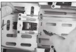
Slide an M3 lock washer, then an M3 washer on an M3 x 15 socket head cap screw. Prepare all four screws.
-
Place a drop of threadlock on each of the screws. Secure the tail wheel bracket in the fuselage using the screws from the previous step and a 2.5mm hex wrench.
-
Slide the cables into the tubes in the fuselage. Retrieve the cables inside the fuselage.
natural_image
Close-up of a hand holding a small metallic tool with a black connector (no visible text or symbols)
natural_image
Close-up of a mechanical lever component with attached bracket and connecting rod (no visible text or symbols)
natural_image
Five black plastic screwdrivers arranged on a plain white surface (no text or symbols visible)
natural_image
Close-up of a mechanical assembly with metal components and a hand holding a tool (no visible text or symbols)
natural_image
Close-up of a transparent cylindrical mechanical component with internal channels (no visible text or symbols)- Slide a sleeve on one end of the cable. Pass the cable through the hole in the cable fi tting. Pass the cable back through the sleeve. With the rudder servo and tail wheel centered, apply light tension on the cable. Use crimping pliers to secure the sleeve to the cable.
→ The servo arm can be removed from the servo if necessary. Use caution to not press too hard and cut the crimp instead of securing it to the wire.
→ Repeat the process to secure both cables.
→ The cables may stretch slightly over time. Periodically check the cables to make sure there is still light tension on them. Use side cutters to trim any excess cable to prevent it from interfering with the operation of the model.
-
Secure the rudder servo arm using the screw provided with the rudder.
-
Place the tail wheel cover back on the fuselage.
-
Use hobby scissors to cut a slot in the fairing so it can be placed over the tail wheel assembly.
natural_image
Close-up of hands installing or adjusting a mechanical component with a tool (no visible text or symbols)
natural_image
Close-up of a computer motherboard with a hand holding a cable and a pen, no visible text or symbols
natural_image
Close-up of a mechanical component with a metallic ring and striped pattern, no visible text or symbols
natural_image
Close-up of hands holding a metallic object with a pointed tip (no visible text or symbols)- Glue the tail wheel fairing to the tail wheel cover using contact adhesive. Make sure not to glue the cover to the fuselage in case the cover requires removal to access the tail gear.
natural_image
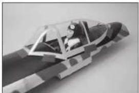
Close-up of a robotic arm operating on a cylindrical mechanical component (no visible text or symbols)PILOT AND CANOPY INSTALLATION
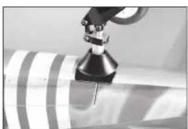
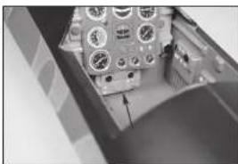
- When fitting the pilot in the cockpit, the lower portion of the instrument panel must be removed.
→ Production models may not need the lower portion of the instrument panel removed. - Carefully remove the lower instrument panel using a hobby knife and #11 blade.
- Use contact adhesive to glue the pilot in the cockpit. Allow the adhesive to fully cure before proceeding.
- Glue the head rest in position using medium CA or contact adhesive.
- Glue the control stick in the cockpit using medium CA or 5-minute epoxy. Position the control stick near the hands of the pilot when a pilot has been installed.
natural_image
Close-up of an aircraft cockpit with visible instrument dial and control panel (no text or symbols)
natural_image
Close-up of a hand holding a small electronic device with control knobs and buttons (no visible text or symbols)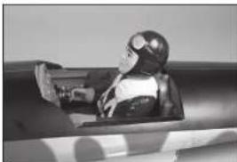
natural_image
Black-and-white photo of a person in a futuristic helmet and goggles, seated in a vehicle (no visible text or symbols)
natural_image
Close-up of a mechanical component with a spherical object inside, possibly a tool or device (no visible text or symbols)
natural_image
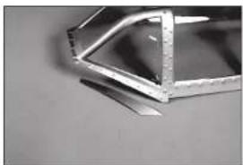
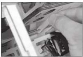
Cross-sectional view of a mechanical device showing internal components (no visible text or symbols)- It may be necessary to trim excess material from the canopy. Use hobby scissors to trim the canopy, then use medium grit sandpaper to smooth the edges.
natural_image
Close-up of a metallic structural component with triangular and rectangular elements (no visible text or symbols)- Use medium-grit sandpaper to lightly sand the inside edge of the canopy where it contacts the canopy hatch. Clean the sanded area using a paper towel and isopropyl alcohol to remove any debris or oils. This provides the surface texture necessary for the adhesive to bond to.
natural_image
Close-up of a hand holding a small metallic object with grid-like surfaces (no visible text or symbols)- Use canopy glue or contact adhesive to glue the canopy to the canopy hatch. Use tape to hold the canopy in position until the adhesive fully cures.
natural_image
3D rendered model of a futuristic jet cockpit with visible cockpit and fuselage (no text or symbols)Do not use CA when gluing the canopy. When CA cures, it releases gases that can fog the canopy and detract from its appearance.
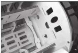
ELECTRIC MOTOR INSTALLATION
As with many scale warbirds, the Ki-43 Oscar has a short nose moment. It maybe necessary to add nose weight depending on what power system is used. Be aware of this when assembling and try to keep all components as far forward in the fuselage as possible.
natural_image
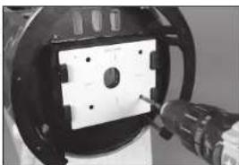
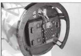
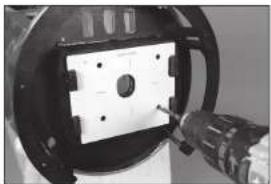
Close-up of a mechanical component with a hand holding a tool, showing a circular housing and mounting holes (no text or symbols visible)- Place the mounting template on the fi rewall. Use low-tack tape to hold the template in position. Use a drill and 1/4-inch (6mm) drill bit to drill the four holes in the fi rewall to attach the motor.
→ When using power systems other than the recommended choices, we advise using the mounting template as a test to ensure hole alignment before drilling the firewall.
natural_image
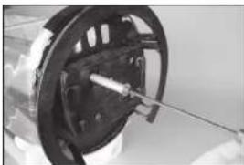
Close-up of a mechanical component with a wire and shaft, no visible text or symbols- Use the screws and standoffs to draw the blind nuts into the fl rewall from inside the fuselage.
natural_image
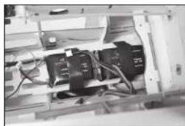
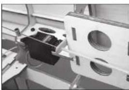
Close-up of a mechanical component with internal channels and mounting holes (no visible text or symbols)- Solder any connectors necessary to connect the speed control to the motor and battery. Secure the speed control to the firewall using screws or tie wraps.
natural_image
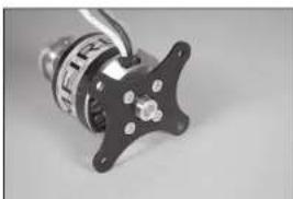
Close-up of a mechanical component with internal circuitry and mounting brackets (no visible text or symbols)- Attach the mount to the motor using the hardware Included with the motor. Use a drop of threadlock on each screw to prevent them from vibrating loose.
natural_image
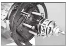
Close-up of a mechanical component with a star-shaped base and metallic shaft (no visible text or symbols)-
Attach your motor to the firewall using the aluminum standoffs and screws. Use a drop of threadlock on each screw to prevent them from vibrating loose. Connect the leads between the speed control and motor. Secure the leads so they don't interfere with the operation of the motor.
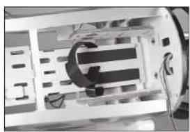
-
Secure the battery for the radio system in the lower section of the fuselage. Use hook and loop tape and hook and loop straps to keep the battery secure.
-
Apply a thin layer of 5-minute epoxy to the battery tray where the hook and loop will be attached. Allow the epoxy to fully cure before applying hook and loop tape to the battery tray.
→ The adhesive on the hook and loop tape will not adhere to the raw wood. Using epoxy creates a surface suitable for the hook and loop adhesive.
- Apply the mating hook and loop tape to the batteries.
→ Do not cover safety warnings on the battery with hook and loop tape.
- Use hook and loop straps around the battery tray to secure the batteries to the tray.
→ Apply a small amount of 5-minute epoxy to the straps to secure them to the battery tray. This will prevent them from falling through the holes when the battery is removed.
natural_image
Close-up of a mechanical assembly with gears and shafts (no visible text or symbols)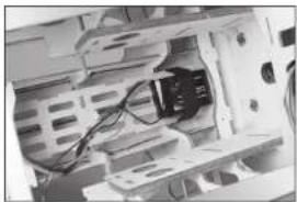
natural_image
Interior view of a computer motherboard showing CPU socket, drive bays, and cable (no visible text or labels)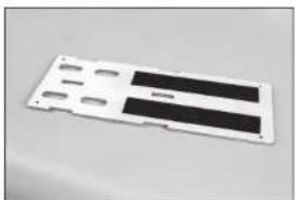
natural_image
White plastic electronic component with black tab and slots, no visible text or symbols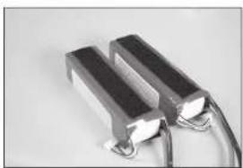
natural_image
Close-up of two metallic USB flash drives with a coiled cable (no text or symbols visible)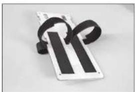
natural_image
Close-up of a white rectangular object with black ribbons, resembling a device or component (no visible text or symbols)-
Prepare and harden the holes in the fuselage for the battery tray screws using an M3 x 15 sheet metal screw and thin CA. Secure the battery tray in the fuselage using four M3 x 15 sheet metal screws and four M3 washers.
-
Secure the batteries in the fuselage using the hook and loop straps. The position of the batteries can be moved to help balance the model.
natural_image
Close-up of a mechanical device interior with visible internal components and wiring (no text or symbols)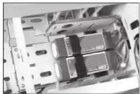
natural_image
Interior view of an electronic device showing internal components and wiring (no visible text or symbols)GAS ENGINE INSTALLATION
As with many scale warbirds, the Ki-43 Oscar has a short nose moment. It maybe necessary to add nose weight depending on what power system is used. Be aware of this when assembling and try to keep all components as far forward in the fuselage as possible.
- Place the mounting template on the fi rewall. Use low-tack tape to hold the template in position. Use a drill and 1/4-inch (6mm) drill bit to drill the four holes in the fi rewall to attach the motor.
→ When using power systems other than the recommended choices, we advise using the mounting template as a test to ensure hole alignment before drilling the firewall.
-
Use the screws and standoffs to draw the blind nuts into the fl rewall from inside the fuselage.
-
Use a drill and 9/64-inch (3.5mm) drill bit to drill the hole for the throttle pushrod.
The location shown is for the Evolution 62GX. Make sure to properly locate the throttle tube when using other engines.
natural_image
Close-up of a mechanical component with a tool inserted, showing a circular opening and a black housing (no visible text or symbols)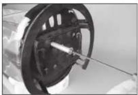
natural_image
Close-up of a mechanical component with a rod inserted, no visible text or symbols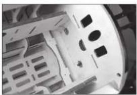
natural_image
Close-up of a mechanical component with internal cavities and mounting holes (no visible text or symbols)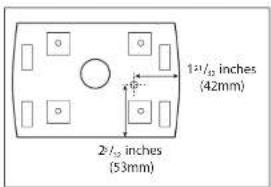
-
Secure the batteries for the radio system and ignition in the lower section of the fuselage. Use hook and loop tape and hook and loop straps to keep the batteries secure.
-
Use medium grit sandpaper to lightly sand the pushrod tube. Remove any oils or debris from the tube using a paper towel and isopropyl alcohol.
-
Slide the tube into the hole in the fi rewall. Leave 1/4 Inch (6mm) of the tube protruding from the fi rewall. Use medium CA to glue the tube in place.
-
Use side cutters to trim the pushrod tube 3/16 inch (5mm) behind the edge of the inner fuselage side.
-
Use a drill and 9/64-Inch (3.5mm) drill bit to drill a hole in a mixing stick. Cut the stick to a length of 1^1/2 inches (38mm). This will be the rear support for the throttle pushrod tube.
natural_image
Interior view of an electronic device with visible components and wiring (no text or symbols)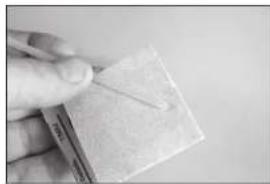
natural_image
Close-up of a hand holding a small rectangular object with a thin wire, possibly a tool or marker (no visible text or symbols)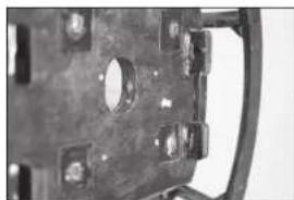
natural_image
Close-up of a mechanical component with bolt holes and mounting holes (no visible text or symbols)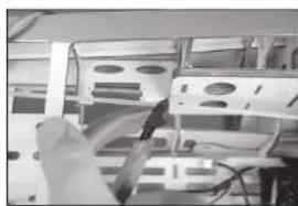
natural_image
Close-up of a hand holding a tool interacting with a rack of electronic equipment (no visible text or symbols)
natural_image
Simple white rectangular object on a plain surface with faint markings (no text or symbols)- Slide the support on the pushrod tube.
natural_image
Close-up of hands holding a small electronic component (no visible text or symbols)- Center the servo using the radio system and install the servo arm on the servo perpendicular to the servo center line. Make sure to slide the connector on the pushrod wire. Use side cutters to remove any arms that may interfere with the operation of the servo.
natural_image
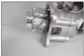
Close-up of a mechanical assembly with no visible text or symbols- Connect the Z-bend in the pushrod to the carburetor arm.
natural_image
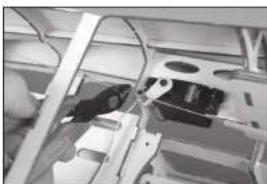
Close-up of a mechanical assembly with metallic components and wiring (no visible text or symbols)- Move the carburetor and servo to the low-throttle position and tighten the setscrew securing the pushrod to the connector at the servo. Use slide cutters to trim the excess wire. Check the operation of the carburetor using the radio system. Make any adjustments necessary to fully open and close the carburetor using the radio system.

natural_image
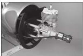
Close-up of a mechanical assembly with wires and components, no visible text or symbols- Guide the throttle pushrod into the pushrod tube. Attach the engine to the fi rewall using four spacers, four machine screws, and four washers. Apply a drop of threadlock on the end of each screw before installation.
natural_image
Close-up of a mechanical engine component with internal gears and housing (no visible text or symbols)- Use side cutters to remove any excess pushrod wire that may interfere with the operation of the throttle servo.
natural_image
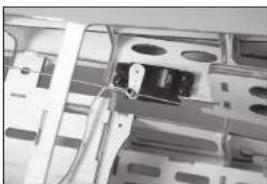
Interior view of a vehicle cabin with seats and overhead equipment (no visible text or symbols)- Prepare the holes in the fuselage for the throttle servo by threading a screw into each hole. Remove the screws and place 2 to 3 drops of thin CA in each hole to harden the surrounding wood. Once the CA has fully cured, install the throttle servo with the servo shaft toward the rear of the fuselage.
natural_image
Interior view of a server rack with ventilation slots and cables (no visible text or symbols)- Use 15-minute epoxy to glue the pushrod tube support to the rear edge of the inner fuselage side.
natural_image
Close-up of a mechanical assembly with circular components and a black housing (no visible text or symbols)- Mount the throttle servo connector in the throttle servo arm so it is 7/16-inch (11mm) from the center of the servo arm. Place a drop of canopy glue on the M2 nut, then install it on the underside of the arm to secure the connector.
natural_image
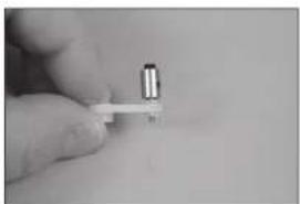
Close-up of a hand holding a small cylindrical object with a white base (no visible text or symbols)FUEL TANK INSTALLATION
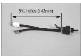
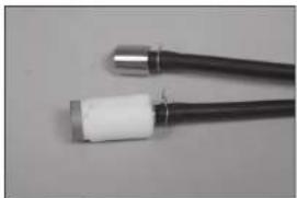
- Cut a piece of fuel tubing that will result in the end of the clunk being 5½ inches (143mm) from the back of the aluminum plate.
- Secure the tubing to the clunk and stopper using thin wire. This will keep the tubing from sliding loose inside the tank. Make sure to use the clunk supplied with your engine.
→ A second clunk can be installed to provide a line to fuel/de-fuel your aircraft.
→ We recommend using a clunk with a filter for all engine installations.
natural_image
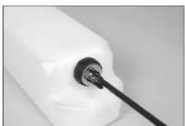
Close-up of two black cables with metallic connectors and white plastic caps (no text or symbols visible)- Insert the clunks into the tank. Install the larger clunk, then the small clunk. The vent line will angle toward the top of the fuel tank.
natural_image
Close-up of a hand holding a small black object with a curved line, next to a white plastic container (no visible text or symbols)- Mark the lines from the tank so the fuel lines can be identified from outside the tank. Tighten the screw in the stopper using a #1 Phillips screwdriver.
→ Check that both clunks can move freely inside the tank. If not, adjust the tubing from outside the tank so they can move freely to ensure consistent fuel flow to the engine.
natural_image
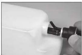
Close-up of a white plastic container with a black cable inserted (no visible text or symbols)- Use a hobby knife with a #11 blade to remove the covering from the fuselage for the fi ll line fi tting. Install the fi tting in the fuselage.
The fill line can also be left inside the fuselage to retain the scale look of the model. The removal of the canopy hatch will be required to add fuel to the fuel tank.

natural_image
Interior view of a storage or warehouse with a cow-shaped container and metal shelving (no visible text or symbols)-
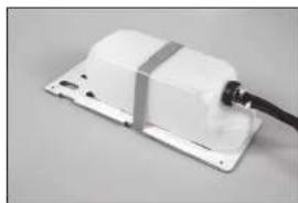
Secure the fuel tank to the fuel tank tray using hook and loop straps Secure 7½ inch (190mm) pieces of fuel line to the three lines exiting the tank. Use tie wraps to prevent the lines from sliding loose.
-
Prepare and harden the holes in the fuselage for the fuel tank tray screws using an M3 x 15 sheet metal screw and thin CA. Secure the fuel tank tray in the fuselage using four M3 x 15 sheet metal screws and four M3 washers.
-
Pass the fi II line through the fi tting in the fuselage. Insert the fi II plug in the fi II line from the tank.
-
Press the plug into the fi tting to secure the fi ll line. Route the vent line from the tank to the bottom of the fuselage. Use a fi tting at the underneath the fuselage to secure the vent line.
-
Connect the line from the fil itered clunk to the carburetor. Use a tie wrap to secure the line to the carburetor.
→ Use a filter between the fuel tank and carburetor to avoid the potential of debris that could be in the fuel from entering the carburetor and engine.
natural_image
White electronic device with a black cable inserted, mounted on a flat base (no visible text or symbols)
natural_image
Interior view of a computer room showing internal components and wiring (no visible text or symbols)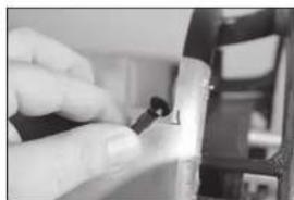
natural_image
Close-up of a hand holding a small black object, possibly a tool or device, with no visible text or symbols.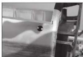
natural_image
Interior view of a room with shelves and a ladder, no visible text or symbols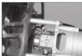
natural_image
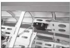
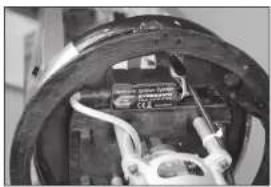
Close-up of a mechanical assembly with metallic components and a central component (no visible text or symbols)- Mount the ignition module to the fi rewall. Use the instructions provided with the engine to connect the module to the engine and ignition battery.
natural_image
Close-up of a mechanical component with visible wiring and components (no text or symbols)RETRACT AIR SYSTEM INSTALLATION
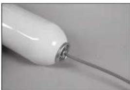
- Cut a 12-inch (305mm) piece of air line and attach it to the air tank.
→ Use a heat gun on low to soften the air lines slightly so they will slide on the fittings.
natural_image
Close-up of a white cylindrical object with a metallic wire inserted, no visible text or symbols.- Remove the servo arm from the rudder servo, Place straps around the tank in the fuselage.

natural_image
Close-up of internal mechanical components with no visible text or symbols- Apply a small amount of contact adhesive on the tray. Use the straps to secure the air tank in the fuselage.
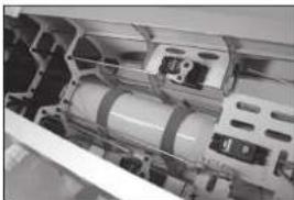
natural_image
Close-up of internal mechanical components with no visible text or symbols- Route the air line under the servo tray to the location for the air valve.
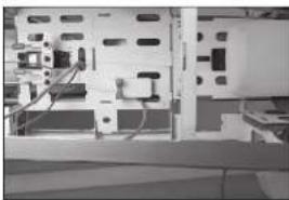
natural_image
Interior view of a computer setup with monitor, keyboard, and mouse (no visible text or labels)- Cut two 4 inch (102mm) pieces of orange air line and one 4 inch (102mm) piece of blue air line. Attach the orange air lines to the fi tting near the end and center fi ttings of the air valve, and the blue air line to the fi tting near the actuator.
Do not remove the actuator from the valve body as it will damage the O-rings and cause an air leak in the valve.
→ Use a heat gun on low to soften the air lines slightly so they will slide on the fittings.
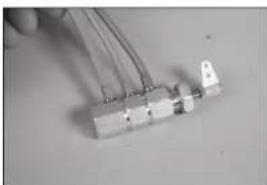
natural_image
Close-up of a small electronic component with wires and connectors (no visible text or symbols)- Secure the air valve in the fuselage. Use a 14mm wrench to tighten the nut, securing the valve in place.
natural_image
Close-up of a computer motherboard with visible circuit breakers and connectors (no text or symbols)- Prepare the holes in the fuselage for the retract valve servo by threading a screw into each hole. Remove the screws and place 2 to 3 drops of thin CA in each hole to harden the surrounding wood. Once the CA has fully cured, install the retract valve servo with the servo shaft toward the rear of the fuselage.
natural_image
Close-up of a mechanical assembly with visible components and no readable text or symbols- Insert the Z-bend of the retract valve pushrod through the hole in the actuator.
natural_image
Close-up of hands operating a mechanical device with no visible text or symbols- Mount the servo connector in the servo arm so it is 11/32-inch (9mm) from the center of the servo arm. Place a drop of canopy glue on the M2 nut, then install it on the underside of the arm to secure the connector. Set the throws for the retract servo to 0% in both directions. Center the actuator as close to center as possible, then tighten the setscrew securing the pushrod in the connector.
natural_image
Close-up of electronic components with visible wiring and connectors (no text or symbols)→ It does not require much throw to operate the valve. Make sure not to damage the valve using too much throw at the servo.
- Slowly increase the servo throw at the radio system to move the actuator into the valve. Make sure not to bottom out the actuator and damage the valve.
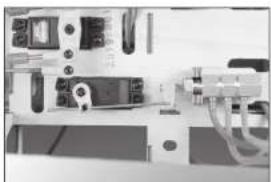
natural_image
Interior view of a laboratory or industrial equipment setup with control panels and tubing (no visible text or symbols)- Toggle the switch at the radio and slowly increase the throw until the edge of the actuator is flush with the edge of the valve body.
→ Make sure not to pull the actuator out of the valve body and damage the O-rings.
- Connect a Y fl tting to the tube from the center of the valve. Fully press the air line into the fl tting.
→ The air lines can be removed by pressing the shoulder against the body of the fitting and pulling the air lines free.
- Cut a 2-inch (51mm) piece of air line and connect the fl ll valve. The arrow will point to the fi tting/valve. Attach the line from the air tank to the fi tting.
The arrow indicates the flow of air from the external fill pump into the retract system. There is a check valve inside the valve that stops air from flowing the other way and emptying the air tank.
- Connect the remaining Y fi ttings for the up and down air lines. Use air line colors that match those from the valve to differentiate the operation of the retracts. Route the air lines in the fuselage along the edges of the radio tray toward the openings for the wing. Secure all the air lines and fi ttings in the fuselage. Add fi ttings at the ends of the air lines to connect the air lines from the retracts in the wing panels.
→ With the push-in type pneumatic connectors it is important to make sure the air line is pushed all the way into the air connectors to seal the air lines. Failure to do so will result in air leaks.
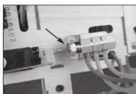
natural_image
Close-up of a computer motherboard with visible wiring and a black arrow pointing to a component (no text or symbols)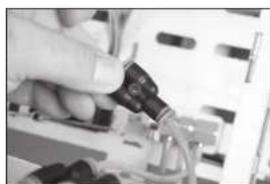
natural_image
Close-up of a hand inserting electronic components into a circuit board (no visible text or symbols)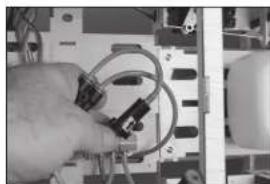
natural_image
Close-up of hands holding a coiled cable or wire component mounted on an electronic circuit board (no visible text or symbols)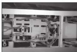
natural_image
Interior view of an electronic device showing internal circuitry and wiring (no visible text or symbols)RECEIVER INSTALLATION
-
Install the receiver in the fuselage. Secure the receiver using the methods included in the receiver or radio instructions.
-
Mount any remote receivers in the fuselage using hook and loop tape. Use the instructions provided with the receiver to orient the remote receivers in the fuselage for the optimum operation of the receiver.
→ Apply a small amount of 5-minute epoxy to the hook and loop tape to secure them in the fuselage.
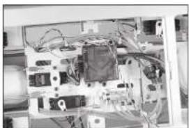
natural_image
Interior view of an electronic device with visible circuitry and wiring (no text or symbols)
natural_image
Interior view of a room with shelves and equipment (no visible text or symbols)
natural_image
Interior view of a technical enclosure or enclosure with exposed wiring and internal components (no visible text or symbols)
natural_image
Close-up of a white aircraft fuselage opening a cylindrical structure (no visible text or symbols)COWLING AND SPINNER INSTALLATION
The spinner cone has been prepared with the slots for the propeller. Most engines of this size use four bolts to retain the propeller. Careful positioning of the drilled holes is required to make sure the propeller aligns with the cutouts in the spinner cone.
→ We recommend preparing at least two propellers in case a new propeller is required when out flying the model.
-
Place the washer from the engine on the spinner backplate. Mark the locations for the propeller mounting screws using a felt-tipped pen.
-
Remove the washer from the backplate. Use a drill and 7/32-inch (5mm) drill bit to drill the holes for the propeller mounting screws.
→ A drill press is highly recommended for drilling the holes to guarantee the holes are properly aligned when installing the propeller.
-
Use a stepped reamer or bolt through the spinner back plate and propeller to hold them in alignment so the bolt holes for attaching the propeller can be marked.
-
Use the four M3 x 10 socket head cap screws to secure the spinner cone to the back plate. Use a 3mm hex wrench to tighten the screws. Position the propeller so it does not contact the spinner cone. Use a pin vise and 3/16-inch (4.5mm) drill bit to drill and indent or marker for the mounting bolt locations.
→ It may be necessary to trim the spinner cone to clear the propeller depending on the choice of propellers.
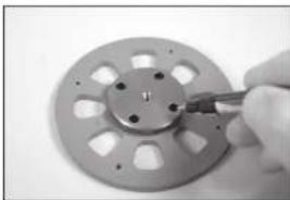
natural_image
Close-up of a hand using a tool to adjust a circular mechanical component with holes (no text or symbols visible)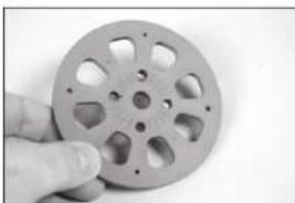
natural_image
Hand holding a metallic film reel with multiple holes (no text or symbols visible)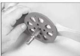
natural_image
Close-up of hands holding a metallic cylindrical component with a metal rod inserted (no visible text or symbols)
natural_image
Close-up of a mechanical component with a cylindrical housing and a metal rod inserted (no visible text or symbols)- Disassemble the spinner and remove the propeller. Use a drill and 7/32-inch (5mm) drill bit to drill the holes in the propeller for the mounting screws.
→ A drill press is highly recommended for drilling the holes to guarantee the holes are properly aligned when installing the propeller.
- Remove the material in the center of the dummy radial for the propeller shaft and drive washer for your particular motor.
The dummy engine is supplied unpainted. It is functional as an air baffle which helps direct air over the gas engines cylinder head. Failure to fit the dummy engine may result in your gas engine overheating due to poor airflow through the cowling vents.
-
The top of the radial engine is indicated by two indentations that will align with the gun exits in the cowling. Use this as a reference when trimming the engine.
-
Gas: Trim the dummy radial engine to allow air to pass over the engine and to clear the carburetor if necessary. EP: Trim the material between the cylinders of the dummy radial engine to allow cooling air to pass across the motor and ESC.
→ The photo shows the radial engine prepared for the gas engine installation.
The dummy radial engine can be detailed using paint before securing it in the cowling. Make sure to test any paints on the trimmed pieces to make sure they are compatible with the plastic.
- Use sandpaper to remove the paint from the dummy radial where it contacts the inside of the cowling. This will increase the bond of the adhesive to the dummy radial. Use 15-minute epoxy to glue the radial engine inside the cowling. Allow the epoxy to fully cure before proceeding.
natural_image
Close-up of a metallic blade with four small holes, possibly a tool or component (no text or symbols visible)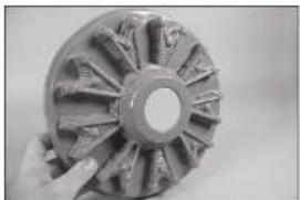
natural_image
Close-up of a hand holding a metallic gear or impeller with visible blades and central hub (no text or symbols)
natural_image
Close-up of a mechanical component with multiple teeth and directional arrows indicating motion (no text or symbols)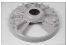
natural_image
Close-up of a mechanical gear or wheel component with radial grooves and central bore (no visible text or symbols)
natural_image
Close-up of a mechanical component with internal gear-like structure (no visible text or symbols)-
Place a piece of clear plastic between the cowl mounts and the cowl ring. Secure the cowl mounts to the fuselage using the M4 x 15 socket head cap screws, M4 lock washer and M4 washer. Align the mount with the cowl ring and tighten the hardware using a 3mm hex wrench.
-
Slide the cowling into position. Center the drive washer in the opening.
-
Attach the propeller to the motor shaft using the hardware included with the engine. Position the cowling so the propeller is equal distance from the cowling when rotated.
-
Use thin CA to tack glue the mounts to the cowling.
The mounts will be removed to be glued securely in the following steps. Do not use excessive amounts of glue in this step.
- Carefully remove the screws and cowling from the fuselage. Use a felt-tipped pen to trace the outline of the mounts on the inside of the cowling.
natural_image
Close-up of a mechanical component with metallic rods and a small rectangular block (no visible text or symbols)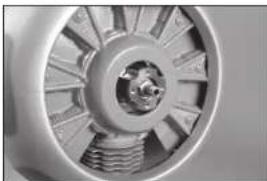
natural_image
Close-up of a mechanical component with radial blades and central hub (no visible text or symbols)
natural_image
Close-up of a white cylindrical object with abstract black patterns, possibly a container or container (no visible text or symbols)
natural_image
Close-up of a person's hand holding an object, possibly a tool or device, against a blurred background (no visible text or symbols)
natural_image
Close-up of hands using a pen to apply a small electronic component (no visible text or symbols)- Remove the mounts and use medium grit sandpaper to sand the area inside the cowling where the mounts rest, and an area at least 1/2 inch (13mm) outside of the area marked. Use a paper towel and isopropyl alcohol to remove any oils or debris from the inside of the cowling.
→ Preparation for gluing the mounts is important to guarantee the adhesive can properly bond the mounts to the inside of the cowling.
-
Mix 1/2 ounce (15ml) of 30-minute epoxy. Apply epoxy inside the cowling in the areas for the mounts.
-
Apply epoxy to the mounts using an epoxy brush.
-
Place the mounts in position in the cowling. Allow the epoxy to fully cure before proceeding.
→ Create a fillet extending out 1/2 inch (13mm) from the mounts to increase the bond between the mount and cowling.
- Install the muffler on the engine. Trim the cowling as necessary to clear the muffler or any other parts of the engine that may protrude outside the cowling. Mount the cowling back on the fuselage. Install the spinner backplate, propeller and spinner on the engine.
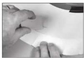
natural_image
Close-up of hands holding a piece of paper or paper with a small object, no visible text or symbols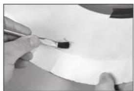
natural_image
Close-up of hands using a tool to apply black ink on a white surface (no text or symbols visible)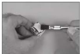
natural_image
Close-up of hands using a tool to adjust or install a small component (no visible text or symbols)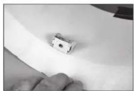
natural_image
Close-up of a small electronic component on a white surface, possibly a switch or sensor, with no visible text or symbols.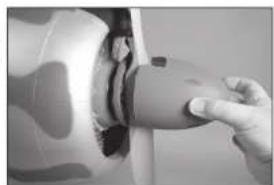
natural_image
Close-up of a hand pressing down on a car wheel rim (no visible text or symbols)CENTER OF GRAVITY
An important part of preparing the aircraft for II light is properly balancing the model. The Center of Gravity range supplied here is a guideline based on testing. Deviation from the measurements we provide is possible and may result in a model that suits your flying style better. Start with the recommended Center of Gravity, then feel free to experiment with different balance points. We advise adjusting progressively and cautiously.
- Attach the wing panels to the fuselage. Make sure to connect the leads from the alleron and flaps to the appropriate leads from the receiver. Make sure the leads, as well as the air lines from the retracts, are not exposed outside the fuselage before tightening the wing bolts. Your model should be flight-ready before balancing.
- The recommended Center of Gravity (CG) location for your model is 6 inches (152.5mm) behind the leading edge of the wing. Take this measurement against the fuselage where the wheel well extends forward of the leading edge of the wing.
- When balancing your model, make sure it is assembled and ready for flight. Support the plane inverted at the marks made on the wing with your fingers or a commercially available balancing stand.
The overall CG range for this model is 75 inches (140–178mm). We recommend starting at the measurement listed above, then adjusting to suit your particular flying style.
→ Nose weight may be required when using lighter weight engines. Move the batteries as far forward in the fuselage to help reduce the amount of weight required.

CAUTION: You must adjust your aircraft's center of d balance your model properly before attempting flights.
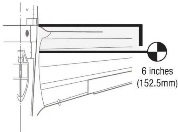
CONTROL THROWS
- Turn on the transmitter and receiver of your model. Check the movement of the rudder using the transmitter. When the stick is moved to the right, the rudder should also move right. Reverse the direction of the servo at the transmitter if necessary.
- Check the movement of the elevator with the radio system. Moving the elevator stick toward the bottom of the transmitter will make the airplane elevator move up.
-
Check the movement of the ailerons with the radio system. Moving the aileron stick to the right will make the right aileron move up and the left aileron move down.
-
Use a ruler to adjust the throw of the elevator, ailerons and rudder.
These are general guidelines for general sport and aerobatic fl ying from our own fl ight tests. You can experiment with higher or lower rates to match your preferred style of fl ying.
Travel Adjust and Sub-Trims are not listed and should be adjusted according to each individual model and preference. Always install the control horns 90 degrees to the servo center line. Use sub-trim as a last resort to center the servos. Always re-bind the radio system once all the control throws are set to keep the servos from moving to their endpoints until the transmitter and receiver connect.
| Surface Rate Direction Throw | |||
| Alleron | High | Up 25/32 inches (20mm) | |
| Down 19/32 inches (15mm) | |||
| Low | Up 19/32 inches (15mm) | ||
| Down 1/2 inches (13mm) | |||
| Elevator | High | Up 1/2 inches (13mm) | |
| Down 1/2 inches (13mm) | |||
| Low | Up 13/32 inches (10mm) | ||
| Down 13/32 inches (10mm) | |||
| Rudder | High | Left | 1^31/_32 inches (50mm) |
| Right | 1^31/_32 inches (50mm) | ||
| Low | Left | 1^3/_16 inches (30mm) | |
| Right | 1^3/_16 inches (30mm) | ||
| Flaps | Take-Off | 1-1^3/_16 inches (25–30mm) | |
| Landing | 1^31/_32-2^5/_8 inches (50–60mm) | ||
PREFLIGHT CHECKLIST
- Charge the transmitter, receiver and motor batteries. Follow the instructions provided with the charger. Follow all manufacturer's instructions for your electronic components.
- Check the radio installation and make sure all control surfaces (aileron, elevator, rudder, and flaps) move correctly (i.e., the correct direction and with the recommended throws).
- Check all the hardware (control homs, servo homs, and clevises) to make sure they are secure and in good condition.
- Prior to each flying session (and especially with a new model), perform a range check of your radio system. See your radio manual for the recommended range and instructions for your particular radio system.
- Check the battery voltage of the transmitter battery. Do not fly below the manufacturer's recommended voltage. Doing so can cause your aircraft to crash.
- Check all hardware (linkages, screws, nuts, and bolts) prior to each day's flight. Ensure that binding does not occur and that all parts are properly secured.
- Ensure all surfaces are moving in the proper manner.
- Perform a ground range check before each day's fl ying session.
- All servo leads and switch harness plugs should be secured in the receiver.
DAILY FLIGHT CHECKS
LIMITED WARRANTY
What this Warranty Covers
Horizon Hobby, LLC, (Horizon) warrants to the original purchaser that the product purchased (the "Product") will be free from defects in materials and workmanship at the date of purchase.
What Is Not Covered
This warranty is not transferable and does not cover (i) cosmetic damage, (ii) damage due to acts of God, accident, misuse, abuse, negligence, commercial use, or due to improper use, installation, operation or maintenance, (iii) modification of or to any part of the Product, (iv) attempted service by anyone other than a Horizon Hobby authorized service center, (v) Product not purchased from an authorized Horizon dealer, (vi) Product not compliant with applicable technical regulations, or (vii) use that violates any applicable laws, rules, or regulations.
OTHER THAN THE EXPRESS WARRANTY ABOVE, HORIZON MAKES NO OTHER WARRANTY OR REPRESENTATION, AND HEREBY DISCLAIMS ANY AND ALL IMPLIED WARRANTIES, INCLUDING, WITHOUT LIMITATION, THE IMPLIED WARRANTIES OF NON-INFRINGEMENT, MERCHANTABILITY AND FITNESS FOR A PARTICULAR PURPOSE. THE PURCHASER ACKNOWLEDGES THAT THEY ALONE HAVE DETERMINED THAT THE PRODUCT WILL SUITABLY MEET THE REQUIREMENTS OF THE PURCHASER'S INTENDED USE.
Purchaser's Remedy
Horizon's sole obligation and purchaser's sole and exclusive remedy shall be that Horizon will, at its option, either (i) service, or (ii) replace, any Product determined by Horizon to be defective. Horizon reserves the right to inspect any and all Product(s) involved in a warranty claim. Service or replacement decisions are at the sole discretion of Horizon. Proof of purchase is required for all warranty claims. SERVICE OR REPLACEMENT AS PROVIDED UNDER THIS WARRANTY IS THE PURCHASER'S SOLE AND EXCLUSIVE REMEDY.
Limitation of Liability
HORIZON SHALL NOT BE LIABLE FOR SPECIAL, INDIRECT, INCIDENTAL OR CONSEQUENTIAL DAMAGES, LOSS OF PROFITS OR PRODUCTION OR COMMERCIAL LOSS IN ANY WAY, REGARDLESS OF WHETHER SUCH CLAIM IS BASED IN CONTRACT, WARRANTY, TORT, NEGLIGENCE, STRICT LIABILITY OR ANY OTHER THEORY OF LIABILITY, EVEN IF HORIZON HAS BEEN ADVISED OF THE POSSIBILITY OF SUCH DAMAGES. Further, in no event shall the liability of Horizon exceed the individual price of the Product on which liability is asserted. As Horizon has no control over use, setup, final assembly, modification or misuse, no liability shall be assumed nor accepted for any resulting damage or Injury. By the act of use, setup or assembly, the user accepts all resulting liability. If you as the purchaser or user are not prepared to accept the liability associated with the use of the Product, purchaser is advised to return the Product immediately in now and unused condition to the place of purchase.
Law
These terms are governed by Illinois law (without regard to conflict of law principals). This warranty gives you specific legal rights, and you may also have other rights which vary from state to state. Horizon reserves the right to change or modify this warranty at any time without notice.
WARRANTY SERVICES
Questions, Assistance, and Services
Your local hobby store and/or place of purchase cannot provide warranty support or service. Once assembly, setup or use of the Product has been started, you must contact your local distributor or Horizon directly. This will enable Horizon to better answer your questions and service you in the event that you may need any assistance. For questions or assistance, please visit our website at www.horizonhobby.com, submit a Product Support Inquiry, or call the toll free telephone number referenced in the Warranty and Service Contact Information section to speak with a Product Support representative.
Inspection or Services
If this Product needs to be inspected or serviced and is compliant in the country you live and use the Product in, please use the Horizon Online Service Request submission process found on our website or call Horizon to obtain a Return Merchandise Authorization (RMA) number. Pack the Product securely using a shipping carton. Please note that original boxes may be included, but are not designed to withstand the rigors of shipping without additional protection. Ship via a carrier that provides tracking and insurance for lost or damaged parcels, as Horizon is not responsible for merchandise until it arrives and is accepted at our facility. An Online Service Request is available at http://www.horizonhobby.com/content/service-center_render-service-center. If you do not have internet access, please contact Horizon Product Support to obtain a RMA number along with instructions for submitting your product for service. When calling Horizon, you will be asked to provide your complete name, street address, email address and phone number where you can be reached during business hours. When sending product into Horizon, please include your RMA number, a list of the included items, and a brief summary of the problem. A copy of your original sales receipt must be included for warranty consideration. Be sure your name, address, and RMA number are clearly written on the outside of the shipping carton.
NOTICE: Do not ship LiPo batteries to Horizon. If you have any issue with a LiPo battery, please contact the appropriate Horizon Product Support office.
Warranty Requirements
For Warranty consideration, you must include your original sales receipt verifying the proof-of-purchase date. Provided warranty conditions have been met, your Product will be serviced or replaced free of charge. Service or replacement decisions are at the sole discretion of Horizon.
Non-Warranty Service
Should your service not be covered by warranty, service will be completed and payment will be required without notification or estimate of the expense unless the expense exceeds 50% of the retail purchase cost. By submitting the item for service you are agreeing to payment of the service without notification. Service estimates are available upon request. You must include this request with your item submitted for service. Non-warranty service estimates will be billed a minimum of 12 hour of labor. In addition you will be billed for return freight. Horizon accepts money orders and cashier's checks, as well as Visa, MasterCard, American Express, and Discover cards. By submitting any Item to Horizon for service, you are agreeing to Horizon's Terms and Conditions found on our website http://www.horizonhobby.com/content/service-center_render-service-center.
ATTENTION: Horizon service is limited to Product compliant in the country of use and ownership. If received, a non-compliant Product will not be serviced. Further, the sender will be responsible for arranging return shipment of the un-serviced Product, through a carrier of the sender's choice and at the sender's expense. Horizon will hold non-compliant Product for a period of 60 days from notification, after which it will be discarded.
10/15
WARRANTY AND SERVICE CONTACT INFORMATION
| Country of Purchase | Horizon Hobby Contact Information Address | ||
| United States of America | Horizon Service Center (Repairs and Repair Requests) | servicecenter.horizonhobby.com/RequestForm/ | 2904 Research Road Champaign, IL 61822 |
| Horizon Product Support (Product Technical Assistance) | productsupport@horizonhobby.com877-504-0233 | ||
| Sales | websales@horizonhobby.com800-338-4639 | ||
| European Union | Horizon Technischer Service service@horizonhobby.eu | Hanskampring 9D 22885 Barsbüttel, Germany | |
| Sales: Horizon Hobby GmbH 49 (0) 4121 2655 100 | |||
INSTRUCTIONS FOR DISPOSAL OF WEEE BY USERS IN THE EUROPEAN UNION

This product must not be disposed of with other waste. Instead, it is the user's responsibility to dispose of their waste equipment by handing it over to a designated collections point for the recycling of waste electrical and electronic equipment. The separate collection and recycling of your waste equipment at the time of disposal will help to conserve natural resources and ensure that it is recycled in a manner that protects human health and the environment. For more information about where you can drop off your waste equipment for recycling, please contact your local city office, your household waste disposal service or where you purchased the product.
ACADEMY OF MODEL AERONAUTICS NATIONAL MODEL AIRCRAFT SAFETY CODE
Effective January 1, 2018
A model aircraft is a non-human-carrying device capable of sustained fl light within visual line of sight of the pilot or spotter(s). It may not exceed limitations of this code and is intended exclusively for sport, recreation, education and/or competition. All model fl lights must be conducted in accordance with this safety code and related AMA guidelines, any additional rules specific to the fl ying site, as well as all applicable laws and regulations.
As an AMA member I agree:
- I will not fly a model aircraft in a careless or reckless manner.
- I will not interfere with and will yield the right of way to all human-carrying aircraft using AMA's See and Avoid Guidance and a spotter when appropriate.
- I will not operate any model aircraft while I am under the influence of alcohol or any drug that could adversely affect my ability to safely control the model.
- I will avoid flying directly over unprotected people, moving vehicles, and occupied structures.
- I will fly Free Flight (FF) and Control Line (CL) models in compliance with AMA's safety programming.
- I will maintain visual contact of an RC model aircraft without enhancement other than corrective lenses prescribed to me. When using an advanced flight system, such as an autopilot, or flying First-Person View (FPV), I will comply with AMA's Advanced Flight System programming.
- I will only fly models weighing more than 55 pounds, including fuel, if certified through AMA's Large Model Airplane Program.
- I will only fly a turbine-powered model aircraft in compliance with AMA's Gas Turbine Program.
- I will not fly a powered model outdoors closer than 25 feet to any individual, except for myself or my helper(s) located at the flightline, unless I am taking off and landing, or as otherwise provided in AMA's Competition Regulation.
- I will use an established safety line to separate all model aircraft operations from spectators and bystanders.
For a complete copy of AMA's Safety Handbook please visit:
www.modelaircraft.org/fi les/100.pdf
HINWEIS
natural_image
Interior ceiling view with two transparent square light fixtures and a small dark object on the wall (no visible text or symbols)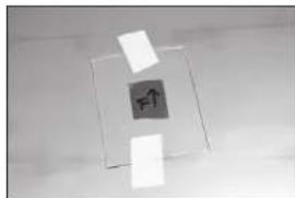
natural_image
Abstract geometric composition with a central upward arrow and surrounding rectangular fragments (no text or symbols)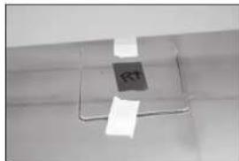
natural_image
Close-up of a ceiling-mounted electrical outlet with metal wiring and a small square component (no visible text or symbols)natural_image
Close-up of a hand holding a white object with a small rectangular outline on a surface (no text or symbols visible)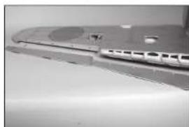
natural_image
Close-up of a silver computer disc with a small inset showing internal components (no visible text or symbols)natural_image
Close-up of a metallic kitchen sink with a bowl and handle (no visible text or symbols)natural_image
Close-up of a metallic electronic component with a small rectangular cutout and mounting brackets (no visible text or symbols)natural_image
Interior view of a stainless steel kitchen appliance with visible sink and door (no text or symbols)natural_image
Interior view of a mechanical assembly with a metallic component and housing (no visible text or symbols)natural_image
Close-up of a metallic mechanical component with internal cavities and mounting holes (no visible text or symbols)natural_image
Close-up of a metallic mechanical component with internal cutouts and a visible hatched area (no text or symbols)natural_image
Close-up of a mechanical or electronic device with metallic components and wiring (no visible text or symbols)natural_image
Close-up of a hand holding a small black screw (no text or symbols visible)natural_image
Interior view of a mechanical device with visible components and wiring (no text or symbols)natural_image
Close-up of a mechanical assembly with a cylindrical component and mounting holes (no visible text or symbols)natural_image
Close-up of a mechanical assembly with a tool inserted into a housing (no visible text or symbols)natural_image
Close-up of a metallic tool or bracket on a plain surface (no text or symbols visible)natural_image
Close-up of a hand holding a dark circular object with a central hole, no visible text or symbols.natural_image
Close-up of a precision tool interacting with a mechanical component (no visible text or symbols)natural_image
Close-up of a mechanical measuring tool interacting with a circular object (no visible text or symbols)natural_image
Close-up of a mechanical assembly with a white sheet and metal components (no visible text or symbols)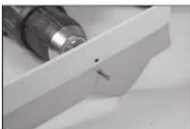
natural_image
Close-up of a metallic tool tip inserted into a white plastic block, no visible text or symbolsnatural_image
Close-up of a mechanical component with a large wheel and metallic frame (no visible text or symbols)natural_image
Close-up of hands assembling a small electronic component with a pen (no visible text or symbols)natural_image
Close-up of hands using a tool to adjust or mark a white strip on a mechanical component (no visible text or symbols)natural_image
Close-up of a precision tool tip cutting through a metal bracket (no visible text or symbols)natural_image
Close-up of a mechanical component with a white curved line and mounting holes (no visible text or symbols)natural_image
Close-up of a metallic mechanical joint or bracket with mounting holes and a vertical rod (no visible text or symbols)natural_image
Close-up of a hand holding a metallic electronic component with a small inset slot (no visible text or symbols)natural_image
Close-up of a metallic mechanical component with a piping bag pouring liquid into a housing (no visible text or symbols)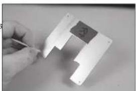
natural_image
Close-up of a hand holding a small electronic component with a square component, no visible text or symbolsnatural_image
Close-up of a metallic mechanical component with mounting holes and a small internal feature (no visible text or symbols)natural_image
Close-up of a metallic mechanical component with mounting holes and a vertical rod (no visible text or symbols)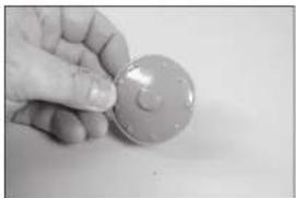
natural_image
Hand holding a circular object with a small mark, possibly a coin or button (no visible text or symbols)
natural_image
Close-up of a circular mechanical component with a central hole and textured surface (no visible text or symbols)MONTAGE DES QUERRUDERS
natural_image
Close-up of a hand holding a small object with a metallic clip, possibly a tool or device (no visible text or symbols)natural_image
Close-up of a hand holding a small object, possibly a tool or device, against a plain background (no text or symbols visible)
natural_image
Close-up of a metallic surface with a small mark labeled '11' (no other text or symbols visible)natural_image
Close-up of a hand holding a knife, showing a curved blade and pointed tip (no text or symbols visible)natural_image
Close-up of a precision tool tip pressing down on a metallic surface (no text or symbols visible)natural_image
Close-up of a metallic object with a curved handle, possibly a tool or bracket, mounted on a dark surface (no visible text or symbols)natural_image
Close-up of a metallic mechanical component with a small white rod inserted into a dark square base (no text or symbols visible)natural_image
Close-up of a hand holding a small object on a metallic surface (no visible text or symbols)natural_image
Close-up of a hand holding a pen over a dark, textured surface (no visible text or symbols)natural_image
Close-up of hands holding a small white tool tip, no visible text or symbolsnatural_image
Close-up of a hand holding a small metallic object with a tool, possibly a component or tool, against a plain background (no text or symbols visible)natural_image
Close-up of hands holding a small tool with a small hole, no visible text or symbols
natural_image
Close-up of a white plastic clip holding a small cylindrical object (no text or symbols visible)
natural_image
Close-up of a hand holding a metallic rod with two small pins inserted (no text or symbols visible)
natural_image
Close-up of hands holding a metallic tool or tool with a small hole, no visible text or symbols
natural_image
Close-up of hands holding a thin, thin wire or filament against a plain background (no text or symbols visible)natural_image
Close-up of hands holding a metal tool with a ring (no visible text or symbols)
natural_image
Close-up of a hand holding a small tool near a curved surface (no text or symbols visible)
natural_image
Close-up of a hand holding a thin wire with a small object, possibly a tool or component (no visible text or symbols)
natural_image
Close-up of a textured surface with a circular hole, possibly a material sample or patterned object (no text or symbols visible)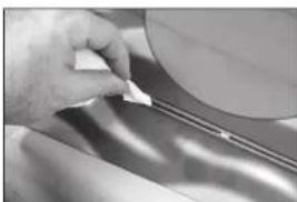
natural_image
Close-up of a hand holding a small object over a metallic surface (no visible text or symbols)natural_image
Close-up of hands holding a circular object with a rectangular extension, no visible text or symbolsMONTAGE DES QUERRUDER-SERVOS
natural_image
Close-up of a hand using tweezers to apply a small mechanical component (no visible text or symbols)
natural_image
Close-up of a hand holding a small black mechanical component with a white clip, attached to a wire (no visible text or symbols)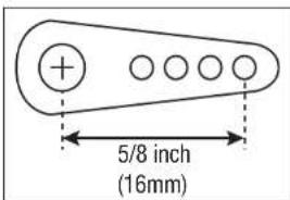
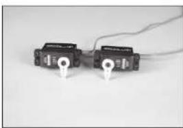
natural_image
Two black electronic components with white connectors and wires, no visible text or symbols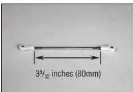
natural_image
Close-up of a hand holding a small electronic device with a white cable, no visible text or symbols on the device itself.natural_image
Close-up of a hand inserting a small electronic component into a device (no visible text or symbols)natural_image
Close-up of hands holding a wire inside an open electrical socket (no visible text or symbols)natural_image
Close-up of a metallic mechanical component with internal cavities and a strap (no visible text or symbols)natural_image
Interior view of a small electronic device with visible internal components and a tool (no text or symbols)natural_image
Close-up of a mechanical component with internal parts and a curved bracket (no visible text or symbols)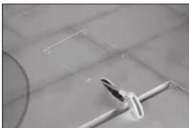
natural_image
Close-up of a white mechanical component attached to a tiled floor, with no visible text or symbols.natural_image
Simple line drawing of a fish-like shape with an arrow pointing to its head (no text or symbols)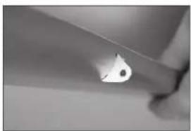
natural_image
Close-up of a metallic blade with a small droplet on its edge (no text or symbols visible)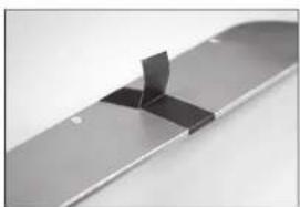
natural_image
Close-up of a metallic electronic component with a clamped slot (no visible text or symbols)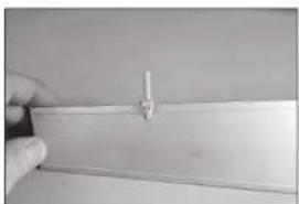
natural_image
Close-up of a hand holding a thin wire or rod against a plain background (no text or symbols visible)natural_image
Close-up of a transparent plastic electronic component with internal traces and mounting holes (no visible text or symbols)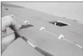
natural_image
Close-up of a hand holding a small object with white markings, possibly part of a fabric or mechanical component (no visible text or symbols)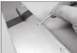
natural_image
Close-up of a hand holding a small tool near a metallic component (no visible text or symbols)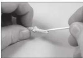
natural_image
Close-up of hands holding a small white object with a string, possibly a tool or tool tip (no visible text or symbols)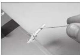
natural_image
Close-up of a hand holding a medical catheter or needle inserted into a tissue (no visible text or symbols)natural_image
Close-up of a hand holding a small electronic component, possibly a battery or connector (no visible text or symbols)natural_image
Close-up of a hand using a tool to cut or adjust a metallic component (no visible text or symbols)natural_image
Close-up of a gloved hand holding a small white object on a surface, with no visible text or symbols.natural_image
Close-up of a hand holding a small electronic component with wires (no visible text or symbols)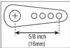
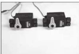
natural_image
Two black mechanical components with metallic levers and wires, placed on a plain white surface (no text or symbols visible)
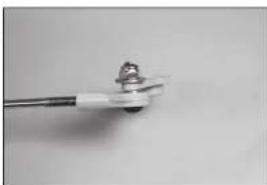
natural_image
Close-up of a small electronic component with a metallic rod and connector (no visible text or symbols)natural_image
Close-up of a white mechanical component with a cylindrical end and a threaded shaft (no text or symbols visible)natural_image
Interior view of an open electrical enclosure with visible internal components (no text or symbols)natural_image
Interior view of an open electrical enclosure with a small device inside (no visible text or symbols)natural_image
Exterior view of a metallic electronic component with internal traces and mounting holes (no visible text or symbols)natural_image
Close-up of a mechanical component with a central knob and flanges (no visible text or symbols)natural_image
Interior view of a mechanical device with no visible text or symbolsnatural_image
Metallic electronic component with curved and rectangular features, no visible text or symbolsnatural_image
Interior view of a room with a framed picture showing internal mechanical components (no visible text or symbols)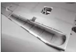
natural_image
Metallic boat hull on a flat surface, no visible text or symbols
natural_image
Close-up of a white train or high-speed train with multiple windows and side compartments (no visible text or symbols)natural_image
Close-up of a transparent plastic sheet with visible surface markings and a circular object on top (no text or symbols)MONTAGE DES ABWURFTANKS

natural_image
Metal mechanical bracket with two side slots and a flat top (no text or symbols visible)natural_image
Exterior view of a modern office building (no signage)natural_image
Exterior view of a modern office building (no signage)MONTAGE DES STABILISATORS
natural_image
Close-up of a hand holding a small white object over a patterned surface (no text or symbols visible)
natural_image
Close-up of hands holding a transparent plastic bag over a patterned fabric (no visible text or symbols)natural_image
Close-up of a metallic object with a white cylindrical object inserted, possibly part of a container or tool (no visible text or symbols)natural_image
Close-up of a textured, patterned object with no visible text or symbolsnatural_image
Close-up of a metallic mechanical component with four circular holes (no text or symbols visible)natural_image
Close-up of a jet aircraft in flight, showing blade and fuselage details (no visible text or symbols)
natural_image
Close-up of a metallic mechanical component with a rod inserted, no visible text or symbols
natural_image
Close-up of a hand holding a small rectangular object with metallic components (no visible text or symbols)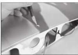
natural_image
Close-up of a mechanical component with a pointed tool and circular features (no visible text or symbols)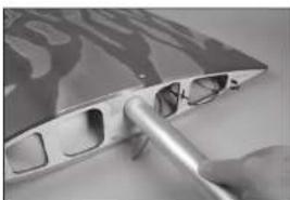
natural_image
Close-up of a hand holding a metallic tool interacting with a metal panel (no visible text or symbols)natural_image
Close-up of a metallic fabric with wavy patterns on the surface (no text or symbols visible)natural_image
Close-up of a hand holding a pen, writing on paper with faint background patterns (no visible text or symbols)natural_image
Architectural floor plan showing room layouts and structural elements (no text or labels visible)natural_image
Close-up of a hand holding a small white object on a dark surface, with no visible text or symbols.natural_image
Close-up of a hand holding a ruler measuring a quantity (no visible text or symbols)natural_image
Close-up of a tool applying material to a white strip, with no visible text or symbolsnatural_image
Close-up of a metal bracket with a tool inserted, showing bolt holes and a small black object (no text or symbols visible)natural_image
Close-up of a hand holding a pen, with blurred background (no visible text or symbols)natural_image
Close-up of metallic mechanical components or clamps on a flat surface (no visible text or symbols)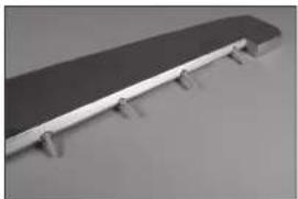
natural_image
Exterior view of a modern office building (no signage)
natural_image
Close-up of a metallic object with embossed text, possibly a shoe or part (no readable text or symbols)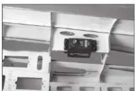
natural_image
Close-up of a mechanical assembly with a central component (no visible text or symbols)
natural_image
Interior view of a modern architectural structure with curved and rectangular elements (no visible text or symbols)natural_image
Abstract grayscale image with vertical striped patterns and layered textures (no text or symbols)
natural_image
Close-up of a mechanical component with a ruler and sheet of paper (no visible text or symbols)
natural_image
Interior view of a transparent filing cabinet with internal compartments and ventilation slots (no visible text or symbols)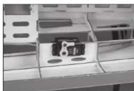
natural_image
Close-up of a mechanical component with a central metallic bracket and mounting holes (no visible text or symbols)
natural_image
Close-up of a metallic mechanical component with a curved edge and flange (no visible text or symbols)natural_image
Close-up of a flat electronic device with metallic connector and black buttons (no visible text or symbols)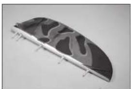
natural_image
Curved metallic object with abstract black and gray patterns, mounted on a flat surface (no text or symbols visible)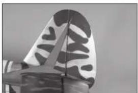
natural_image
Close-up of a metallic butterfly wing with black and white patterned design (no text or symbols visible)natural_image
Close-up of a computer motherboard with visible slots, connectors, and ventilation grilles (no text or symbols)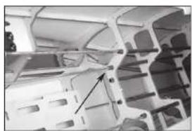
natural_image
Interior view of a vehicle chassis frame with structural ribs and mounting holes (no visible text or symbols)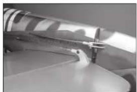
natural_image
Close-up of a mechanical component with a metallic tool inserted, no visible text or symbols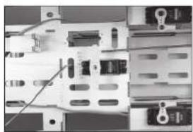
natural_image
Close-up of an electronic circuit board with components and wiring (no visible text or symbols)
natural_image
Two metallic tool holders with handles, no visible text or symbolsnatural_image
Close-up of a mechanical clamp or bracket component (no visible text or symbols)
natural_image
Close-up of an electronic circuit board with visible components and wiring (no text or symbols)MONTAGE DES SPORNRADS
natural_image
Hand holding a small black object with a white circular hole, against a plain background (no text or symbols visible)
natural_image
Close-up of gloved hands holding a small dark object over a surface, no visible text or symbols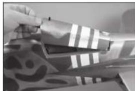
natural_image
Close-up of a hand holding a rolled-up fabric with striped pattern and a smiley face (no text or symbols visible)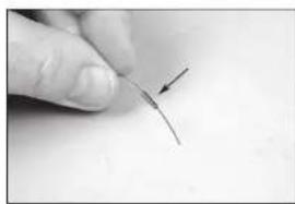
natural_image
Close-up of a finger pointing to a thin, curved wire or filament (no text or symbols visible)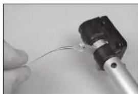
natural_image
Close-up of a hand holding a thin wire with a small metallic component attached (no visible text or symbols)natural_image
Close-up of a hand holding a small mechanical component with a thin wire or filament (no visible text or symbols)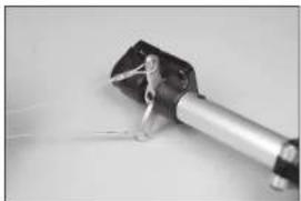
natural_image
Close-up of a mechanical lever component with attached bracket and connecting rod (no visible text or symbols)
natural_image
Five black plastic screwdrivers arranged on a plain white surface (no text or symbols visible)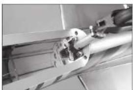
natural_image
Close-up of a mechanical assembly with metal components and a hand holding a tool (no visible text or symbols)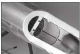
natural_image
Close-up of a transparent cylindrical mechanical component with internal channels (no visible text or symbols)natural_image
Close-up of hands installing or adjusting a mechanical component with a tool (no visible text or symbols)
natural_image
Close-up of a computer motherboard with a hand holding a cable and a small electronic component (no visible text or symbols)
natural_image
Close-up of a mechanical component with a metallic ring and striped pattern, no visible text or symbols
natural_image
Close-up of hands holding a metallic object with a pointed tip (no visible text or symbols)natural_image
Close-up of a robotic arm operating on a cylindrical mechanical component (no visible text or symbols)MONTAGE VON PILOT UND KANZEL
natural_image
Close-up of an aircraft cockpit with visible instrument dial and control panel (no text or symbols)
natural_image
Close-up of a hand holding a small electronic device with control knobs and buttons (no visible text or symbols)
natural_image
Black-and-white photo of a person in a futuristic helmet and goggles, seated in a vehicle (no visible text or symbols)
natural_image
Close-up of a mechanical component with a spherical object inside, possibly a tool or device (no visible text or symbols)
natural_image
Cross-sectional view of a mechanical device showing internal components and housing (no visible text or symbols)natural_image
Close-up of a metallic structural component with triangular and rectangular elements (no visible text or symbols)natural_image
Close-up of a hand holding a small metallic object with grid-like surfaces (no visible text or symbols)natural_image
Model of a futuristic jet aircraft with cockpit and fuselage (no visible text or symbols)natural_image
Close-up of a mechanical component with a tool inserted, showing a circular housing and a black plastic plate (no text or symbols visible)
natural_image
Close-up of a mechanical component with a rod inserted, no visible text or symbols
natural_image
Close-up of a mechanical component with internal cavities and mounting holes (no visible text or symbols)natural_image
Close-up of a mechanical component with internal components and mounting brackets (no visible text or symbols)natural_image
Close-up of a mechanical component with a star-shaped base and metallic shaft (no visible text or symbols)natural_image
Close-up of a white rectangular device with black bands and a black strap, no visible text or symbols.natural_image
Close-up of a mechanical assembly with gears and shafts (no visible text or symbols)natural_image
Interior view of a mechanical device with internal components and wiring (no visible text or symbols)natural_image
Interior view of a computer room showing a computer with cables and a small electronic device (no visible text or symbols)natural_image
Interior view of an electronic device showing internal components and wiring (no visible text or symbols)natural_image
White plastic electronic component with two black rectangular strips, no visible text or symbolsnatural_image
Close-up of two metallic electronic components with wires, no visible text or symbolsMONTAGE DES BENZINMOTORS
natural_image
Close-up of a mechanical component with a tool inserted, showing a circular opening and a black housing (no visible text or symbols)
natural_image
Close-up of a mechanical component with a tool inserted, no visible text or symbols
natural_image
Close-up of a mechanical component with internal cavities and mounting holes (no visible text or symbols)
natural_image
Interior view of an electronic device with visible wiring and components (no text or symbols)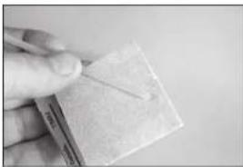
natural_image
Close-up of a hand holding a small, textured object with a diagonal line (no visible text or symbols)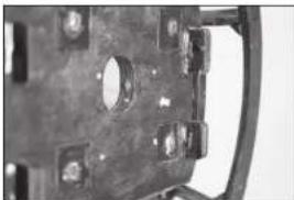
natural_image
Close-up of a mechanical component with circular holes and mounting brackets (no visible text or symbols)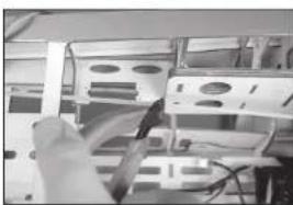
natural_image
Close-up of a hand holding a tool interacting with a rack of electronic components (no visible text or symbols)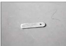
natural_image
Simple white rectangular object on a plain surface with faint markings (no text or symbols)natural_image
Close-up of hands holding a small electronic component (no visible text or symbols)natural_image
Close-up of a mechanical assembly with metallic components and wiring (no visible text or symbols)natural_image
Close-up of a mechanical engine component with internal gears and housing (no visible text or symbols)natural_image
Interior view of a server rack with ventilation grilles and cables (no visible text or labels)natural_image
Close-up of a hand holding a small cylindrical object with a white base (no visible text or symbols)natural_image
Close-up of a mechanical assembly with no visible text or symbols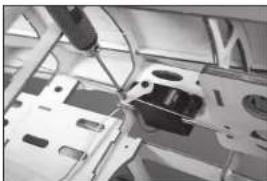
natural_image
Close-up of a mechanical assembly with wires and components, no visible text or symbols
natural_image
Interior view of a vehicle cabin with seats and overhead equipment (no visible text or symbols)
natural_image
Close-up of a mechanical assembly with circular components and a black housing (no visible text or symbols)MONTAGE DES KRAFTSTOFFTANKS
natural_image
Two black cables with metallic connectors, one white and one metallic (no text or symbols visible)natural_image
Close-up of a hand holding a small black object with a curved line, next to a white plastic container (no visible text or symbols)
natural_image
Close-up of a white plastic container with a black cable inserted (no visible text or symbols)
natural_image
Interior view of a storage or warehouse with a cow-shaped container and ladder (no visible text or symbols)natural_image
White electronic device with a black cable inserted, no visible text or symbols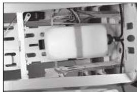
natural_image
Interior view of a computer room showing internal components and wiring (no visible text or symbols)
natural_image
Close-up of a hand holding a small black object, possibly a tool or device, with no visible text or symbols.
natural_image
Interior view of a room with shelves and a ladder, no visible text or symbols
natural_image
Close-up of a mechanical assembly with metallic components and a central component (no visible text or symbols)natural_image
Close-up of a mechanical component with visible wiring and components (no text or symbols)MONTAGE DES LUFTSYSTEMS DES EINZIEHBAREN FAHRWERKS
natural_image
Close-up of a white cylindrical object with a metallic rod inserted, no visible text or symbols
natural_image
Close-up of an electronic device casing with internal components (no visible text or symbols)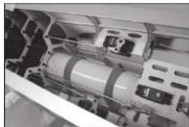
natural_image
Close-up of internal mechanical components, possibly a motor or housing assembly (no visible text or symbols)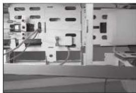
natural_image
Interior view of an electronic device with visible circuitry and components (no text or symbols)
natural_image
Close-up of a small electronic component with wires and connectors (no visible text or symbols)natural_image
Close-up of a computer motherboard with visible circuit breakers and connectors (no text or symbols)natural_image
Close-up of a mechanical assembly with visible components and no readable text or symbolsnatural_image
Close-up of hands operating a mechanical device with no visible text or symbolsnatural_image
Close-up of electronic components with visible wiring and connectors (no text or symbols)natural_image
Interior view of a laboratory or industrial equipment setup with control panels and tubing (no visible text or symbols)natural_image
Close-up of electronic circuit board with visible components and wiring (no readable text or symbols)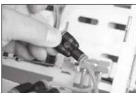
natural_image
Close-up of a hand inserting a small electronic component into a circuit board (no visible text or symbols)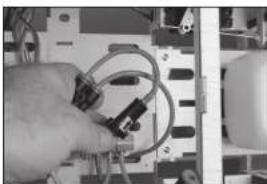
natural_image
Close-up of hands holding a coiled cable or wire next to an electronic device (no visible text or symbols)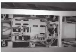
natural_image
Interior view of an electronic device showing internal components and wiring (no visible text or symbols)MONTAGE DES EMPFÄNGERS
natural_image
Interior view of an electronic device with visible circuitry and components (no readable text or symbols)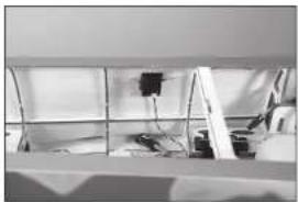
natural_image
Interior view of a room with shelves and equipment (no visible text or symbols)
natural_image
Interior view of a technical apparatus with metal brackets and wiring (no visible text or symbols)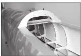
natural_image
Close-up of a white aircraft fuselage opening a cylindrical structure (no visible text or symbols)MONTAGE VON MOTORHAUBE UND SPINNER
natural_image
Close-up of a hand using a tool to adjust a circular mechanical component with holes (no visible text or symbols)
natural_image
Hand holding a metallic film reel with multiple holes (no text or symbols visible)
natural_image
Close-up of hands holding a metallic cylindrical component with a metal rod inserted (no visible text or symbols)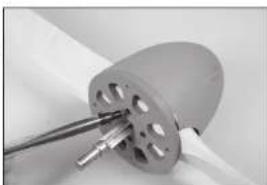
natural_image
Close-up of a mechanical component with a cylindrical housing and metal rod inserted (no visible text or symbols)natural_image
Close-up of a metallic blade with four small holes, possibly a tool or component (no text or symbols visible)
natural_image
Close-up of a hand holding a metallic gear or impeller with visible blades and central hub (no text or symbols)
natural_image
Close-up of a mechanical component with multiple teeth and directional arrows indicating motion (no text or symbols)natural_image
Close-up of a mechanical gear or wheel component with radial grooves and central bore (no visible text or symbols)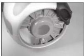
natural_image
Close-up of a mechanical component with internal gear-like structure (no visible text or symbols)natural_image
Close-up of a mechanical component with metallic rods and a small rectangular feature (no visible text or symbols)
natural_image
Close-up of a mechanical component with radial blades and central hub (no visible text or symbols)
natural_image
Close-up of a white cylindrical object with abstract black patterns, possibly a container or container (no visible text or symbols)
natural_image
Close-up of a person's hand holding an object, possibly a tool or device, against a blurred background (no visible text or symbols)
natural_image
Close-up of hands holding a pen and a small electronic component (no visible text or symbols)natural_image
Close-up of hands holding a piece of paper or paper with a small mark, no visible text or symbols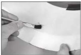
natural_image
Close-up of hands holding a pen writing on a white sheet (no visible text or symbols)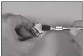
natural_image
Close-up of hands using a tool to apply a small object on a surface (no visible text or symbols)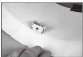
natural_image
Close-up of a small electronic component with a black dot on its surface, resting on a white surface (no visible text or symbols)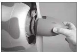
natural_image
Close-up of a hand adjusting a small electronic component (no visible text or symbols)SCHWERPUNKT
RUDERAUSSCHLAG
natural_image
Medical device with a bowl and handle, no visible text or symbolsnatural_image
Interior view of a medical or laboratory device with mechanical components and a spherical object (no visible text or symbols)natural_image
Interior view of a kitchen appliance with stainless steel fixtures and a sink (no visible text or symbols)natural_image
Close-up of a metallic electronic component with a small rectangular cutout and wiring (no visible text or symbols)natural_image
Close-up of a metallic mechanical component with internal cavities and a triangular cutout (no visible text or symbols)natural_image
Interior view of a vehicle showing a car, dashboard, and structural components (no visible text or symbols)natural_image
Close-up of a mechanical assembly with metallic components and wiring (no visible text or symbols)natural_image
Close-up of a metallic mechanical component with visible internal structure and wiring (no text or symbols)natural_image
Close-up of a hand holding a small black nail (no text or symbols visible)natural_image
Close-up of a mechanical assembly with a cylindrical component and mounting holes (no visible text or symbols)natural_image
Close-up of a mechanical assembly with metal components and a tool (no visible text or symbols)natural_image
Close-up of a metallic tool or bracket on a flat surface, with no visible text or symbols.natural_image
Close-up of a hand holding a dark circular object with a central hole, no visible text or symbols.natural_image
Close-up of a mechanical component with a precision tool inserted, showing internal structure (no visible text or symbols)natural_image
Close-up of a mechanical clamp or measuring tool operating a circular tire (no visible text or symbols)natural_image
Close-up of a metallic mechanical component with a white sheet and bolted base (no visible text or symbols)
natural_image
Close-up of a metallic tool inserted into a white plastic block, no visible text or symbolsnatural_image
Close-up of a mechanical component with visible tire and mounting bracket (no text or symbols)
natural_image
Close-up of hands using a tool to adjust or mark a white strip on a mechanical component (no visible text or symbols)
natural_image
Close-up of a mechanical component with a white strip and small black dots, no visible text or symbols
natural_image
Close-up of a metallic mechanical part with a small circular feature, partially held by fingers (no visible text or symbols)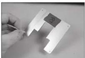
natural_image
Close-up of a hand holding a small electronic component with a dark square on top, next to a white mechanical part (no visible text or symbols)natural_image
Close-up of hands using a power tool to adjust or install electronic components (no visible text or symbols)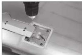
natural_image
Close-up of a precision tool tip cutting through a metal bracket (no visible text or symbols)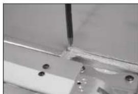
natural_image
Close-up of a metallic bracket with mounting holes and a vertical rod inserted (no visible text or symbols)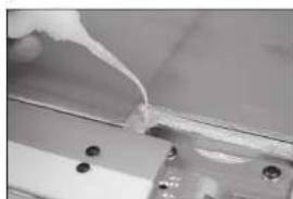
natural_image
Close-up of a mechanical component with a piping bag inserted, showing no visible text or symbols.
natural_image
Close-up of a metallic mechanical component with mounting holes and a transparent housing (no visible text or symbols)natural_image
Close-up of a metallic mechanical component with mounting holes and a central bracket (no visible text or symbols)
natural_image
Hand holding a circular object with a small mark, possibly a button or knob (no text or symbols visible)
natural_image
Close-up of a circular mechanical component with a central hole, possibly a knob or dial (no visible text or symbols)INSTALLATION DE L'AILERON
natural_image
Close-up of hands holding a small metallic object with a white plastic clip, no visible text or symbols
natural_image
Close-up of a hand holding a small object, possibly a tool or device, against a plain background (no text or symbols visible)
natural_image
Close-up of a metallic object with a small mark on the surface (no visible text or symbols)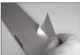
natural_image
Close-up of a hand holding a knife, showing blade and handle (no text or symbols visible)natural_image
Close-up of a precision tool tip interacting with a metallic surface (no visible text or symbols)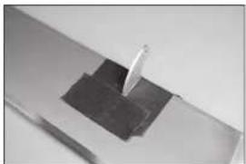
natural_image
Close-up of a metallic mechanical component with a small protrusion on top (no visible text or symbols)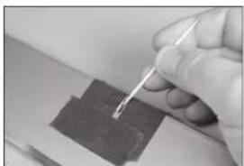
natural_image
Close-up of a hand holding a pen over a dark rectangular object (no visible text or symbols)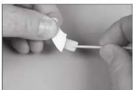
natural_image
Close-up of hands holding a small white object with a string, possibly a tool or component (no visible text or symbols)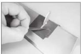
natural_image
Close-up of a hand holding a small object with a dark surface, possibly a tool or component (no visible text or symbols)natural_image
Close-up of a metallic tool interacting with a dark surface (no visible text or symbols)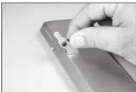
natural_image
Close-up of a hand holding a small object on a metallic surface (no visible text or symbols)natural_image
Close-up of a hand holding a small wire or tool, no visible text or symbols
natural_image
Close-up of a hand holding a small metal clip (no visible text or symbols)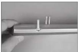
natural_image
Close-up of a hand holding a metallic rod with two small pins inserted (no text or symbols visible)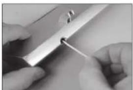
natural_image
Close-up of hands performing a precision task with a tool (no visible text or symbols)
natural_image
Close-up of hands holding a thin, elongated object with a small white mark (no visible text or symbols)natural_image
Close-up of hands holding a metal object with a small metallic hook (no visible text or symbols)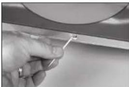
natural_image
Close-up of a hand holding a small tool near a metallic component (no visible text or symbols)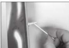
natural_image
Close-up of a hand holding a thin wire with a white rod inserted, against a blurred background (no text or symbols visible)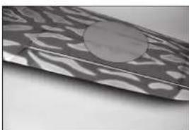
natural_image
Close-up of a textured surface with a circular hole, possibly a disc or lens (no text or symbols visible)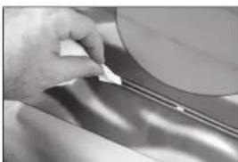
natural_image
Close-up of a hand holding a pen over a curved surface, possibly a tool or device (no visible text or symbols)natural_image
Close-up of hands holding a rectangular object with a circular hole, possibly part of a mechanical or architectural component (no visible text or symbols)INSTALLATION DU SERVO DE L'AILERON
natural_image
Close-up of a hand using tweezers to apply a small mechanical component (no visible text or symbols)natural_image
Close-up of a hand holding a small black device with a white handle, attached to a wire (no visible text or symbols)natural_image
Close-up of two black electrical connectors with white wires, no visible text or symbolsnatural_image
Close-up of a hand holding a small electronic device with a white cable, no visible text or symbols on the device itself.natural_image
Close-up of a hand holding a small electronic component with wires, no visible text or symbolsnatural_image
Close-up of hands holding wires inside an open electrical outlet (no visible text or symbols)natural_image
Close-up of a white car wheel rim with visible internal components and wires (no text or symbols)natural_image
Interior view of a mechanical or electrical component with visible internal components and a tool (no text or symbols)natural_image
Close-up of a ceiling fixture with a mounted component and wiring (no visible text or symbols)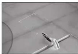
natural_image
Close-up of a white airplane on a tiled floor, no visible text or symbolsMISE EN PLACE DES CHARNIÈRES DES VOLETS
natural_image
Simple line drawing of a fish head with an arrow pointing to it (no text or symbols)
natural_image
Close-up of a metallic blade with a small circular feature, possibly part of a tool or component (no text or symbols visible)natural_image
Close-up of a metallic mechanical component with a folded section (no visible text or symbols)
natural_image
Close-up of a hand holding a thin wire or rod against a plain background (no text or symbols visible)natural_image
Close-up of a metallic electronic component with visible traces and mounting holes (no text or symbols)
natural_image
Close-up of a hand holding a small object with white markings, possibly part of a technical diagram or tool (no visible text or symbols)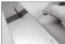
natural_image
Close-up of a hand holding a small tool near a white surface, with no visible text or symbols.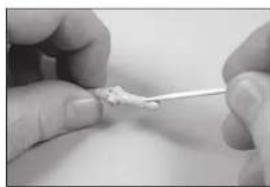
natural_image
Close-up of hands using a pipette to apply a small white substance (no text or symbols visible)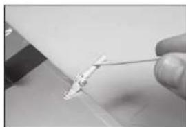
natural_image
Close-up of a hand holding a thin wire with a small object attached (no visible text or symbols)natural_image
Close-up of a hand using a tool to adjust or install electronic components (no visible text or symbols)natural_image
Close-up of a hand pressing down on a metal component with a curved handle (no visible text or symbols)natural_image
Close-up of a hand holding a small white object with a glowing effect, possibly part of a device or tool (no visible text or symbols)natural_image
Close-up of a hand holding a small electronic component with a white handle, against a plain background (no visible text or symbols)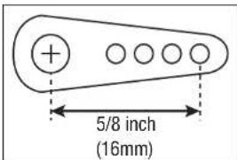

natural_image
Two black mechanical components with metallic fittings and wires, placed on a plain white surface (no text or symbols visible)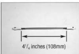
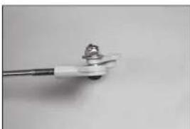
natural_image
Close-up of a metallic tool with a small protrusion and a central screw-like component (no visible text or symbols)natural_image
Close-up of a white mechanical component with a cylindrical end and a threaded shaft (no text or symbols visible)natural_image
Interior view of an open electrical enclosure with internal components (no visible text or symbols)natural_image
Interior view of a small electronic device with an open socket and internal components (no visible text or symbols)natural_image
Metallic electronic component with curved internal structure and mounting holes (no visible text or symbols)natural_image
Close-up of a mechanical component with a central knob and flanges (no visible text or symbols)natural_image
Black-and-white photo of a mechanical device mounted on a wall, no visible text or symbolsnatural_image
Metallic electronic component with rounded edges and a small inset feature (no visible text or symbols)natural_image
Black-and-white photo of a mechanical device with no visible text or symbols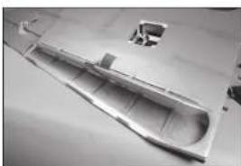
natural_image
Metallic plastic boat hull on a flat surface, no visible text or symbols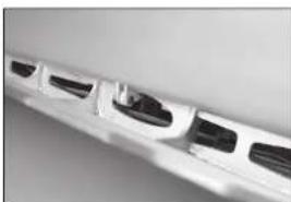
natural_image
Close-up of a white train or high-speed train with multiple windows and side compartments (no visible text or symbols)natural_image
Close-up of a transparent plastic sheet with visible internal markings and a circular object on top (no text or symbols)INSTALLATION DU RÉSERVOIR LARGABLE
natural_image
Metal mechanical bracket with two side slots and a flat top (no text or symbols visible)
natural_image
Exterior view of a modern office building (no signage)natural_image
Exterior view of a modern office building (no signage)INSTALLATION DU STABILISATEUR
natural_image
Close-up of a hand holding a small white object over a metallic surface (no text or symbols visible)
natural_image
Close-up of hands holding a transparent plastic bag over a patterned surface (no text or symbols visible)natural_image
Close-up of a metallic mechanical component with circular cutouts and a pointed tip (no visible text or symbols)natural_image
Close-up of a textured, patterned object resembling a mechanical part or tool (no visible text or symbols)natural_image
Close-up of a metallic bracket with four circular holes, no visible text or symbolsnatural_image
Close-up of a metallic object with abstract patterns and a central hole (no visible text or symbols)
natural_image
Close-up of a metallic mechanical component with a tool inserted, no visible text or symbols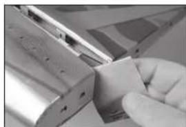
natural_image
Close-up of a hand holding a small rectangular object with metallic components (no visible text or symbols)
natural_image
Close-up of a hand holding a pen, partially obscured by metallic lines (no visible text or symbols)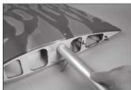
natural_image
Close-up of a hand holding a metallic tool interacting with a curved surface (no visible text or symbols)natural_image
Close-up of a rolled-up fabric with abstract wavy patterns (no text or symbols visible)natural_image
Close-up of a hand holding a pen, writing on paper with blurred background (no visible text or symbols)natural_image
Architectural floor plan view showing room layouts and structural elements (no text or labels visible)natural_image
Close-up of a hand holding a small white object on a dark surface, with no visible text or symbols.natural_image
Close-up of a hand holding a ruler measuring a metal object (no visible text or symbols)natural_image
Close-up of a gloved hand holding a small object over a patterned surface (no visible text or symbols)natural_image
Close-up of a mechanical component with a tool applying material to a surface (no visible text or symbols)natural_image
Close-up of a hand holding a metal tool with a pen-like object on a surface (no visible text or symbols)natural_image
Close-up of metallic mechanical components with no visible text or symbols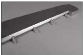
natural_image
Exterior view of a modern office building (no signage)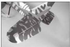
natural_image
Close-up of a metallic airplane with visible propellers and branding (no readable text or symbols)
natural_image
Close-up of a mechanical assembly with a central component and mounting holes (no visible text or symbols)
natural_image
Interior architectural view of a modern building with curved structural elements (no visible text or symbols)natural_image
Abstract grayscale image with vertical striped patterns and layered textures, no visible text or symbols
natural_image
Close-up of a mechanical component with a ruler and flange (no visible text or symbols)
natural_image
Interior view of a technical enclosure or enclosure with internal compartments and no visible text or symbols
natural_image
Close-up of a mechanical component with a metallic housing and mounting holes (no visible text or symbols)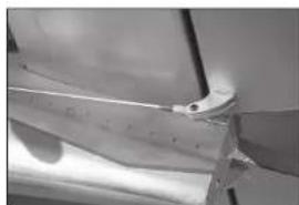
natural_image
Close-up of a metallic mechanical component with a curved edge and flange (no visible text or symbols)INSTALLATION DE LA GOUVERNE DE DIRECTION
natural_image
Close-up of a handheld electronic device with metallic contacts and a patterned cover (no visible text or symbols)
natural_image
Curved metallic object with abstract pattern and mounting pins (no text or symbols visible)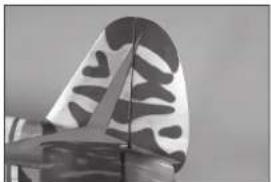
natural_image
Close-up of a butterfly wing with black and white patterned design (no text or symbols visible)INSTALLATION DE LA TRINGLERIE DE LA GOUVERNE DE DIRECTION
natural_image
Close-up of an electronic circuit board with visible components and connectors (no readable text or symbols)
natural_image
Interior view of an automotive chassis frame with structural ribs and mounting holes (no visible text or symbols)
natural_image
Close-up of a metallic tool tip with a ruler, no visible text or symbols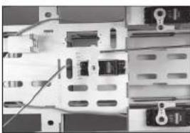
natural_image
Close-up of an electronic circuit board with connectors and components (no visible text or symbols)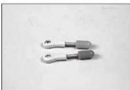
natural_image
Two metallic tool holders with handles, no visible text or symbolsnatural_image
Close-up of a mechanical clamp or bracket component with two handles and a central handle (no text or symbols visible)
natural_image
Close-up of an electronic circuit board with connectors and components (no visible text or symbols)INSTALLATION DE LA ROUE DE QUEUE
natural_image
Hand holding a small black object with a white circular hole, against a plain background (no text or symbols visible)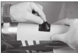
natural_image
Close-up of hands holding a small black object over a surface, possibly a tool or device (no visible text or symbols)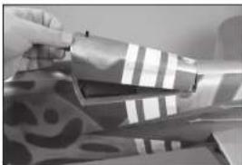
natural_image
Close-up of hands handling a patterned fabric or textile with striped and patterned sections (no visible text or symbols)
natural_image
Close-up of a finger pointing to a thin, curved wire or filament (no text or symbols visible)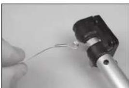
natural_image
Close-up of a hand holding a small wire or cable attached to a mechanical component (no visible text or symbols)natural_image
Close-up of a hand holding a small metallic tool with a black connector (no visible text or symbols)
natural_image
Close-up of a mechanical lever component with attached bracket and connecting rod (no visible text or symbols)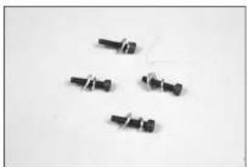
natural_image
Five black plastic screwdrivers arranged on a plain white surface (no text or symbols visible)
natural_image
Close-up of a mechanical assembly with metal components and a cylindrical shaft (no visible text or symbols)
natural_image
Close-up of a transparent cylindrical mechanical component with internal cavities (no visible text or symbols)natural_image
Close-up of hands installing or adjusting a mechanical component with a tool (no visible text or symbols)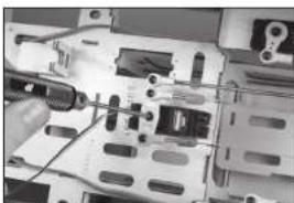
natural_image
Close-up of a computer motherboard with a hand holding a cable and a pen inserted, no visible text or symbols
natural_image
Close-up of a mechanical component with a metallic hook and striped pattern, no visible text or symbols
natural_image
Close-up of hands holding a metallic object with a pointed tip (no visible text or symbols)natural_image
Close-up of a robotic arm operating on a cylindrical mechanical component (no visible text or symbols)INSTALLATION DU PILOTE ET DE LA VERRIÈRE
natural_image
Close-up of an aircraft cockpit with visible instrument dial and control panel (no text or symbols)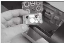
natural_image
Close-up of a hand holding a small electronic device with control knobs and buttons (no visible text or symbols)
natural_image
Black-and-white photo of a person in a futuristic helmet and goggles, seated in a vehicle (no visible text or symbols)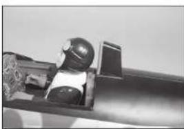
natural_image
Close-up of a mechanical component with a spherical object inside, possibly a tool or device (no visible text or symbols)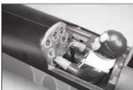
natural_image
Close-up of a mechanical assembly showing internal components and housing (no visible text or symbols)natural_image
Close-up of a metallic structural component with a triangular cutout and angled edge (no text or symbols visible)natural_image
Close-up of a hand holding a small metallic object with grid-like surfaces (no visible text or symbols)natural_image
Model of a fighter jet inside a cockpit, rendered in grayscale (no text or symbols visible)natural_image
Close-up of a mechanical component with a tool inserted, showing a circular housing and mounting holes (no text or symbols visible)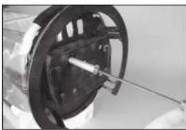
natural_image
Close-up of a mechanical component with a rod inserted, no visible text or symbols
natural_image
Close-up of a mechanical component with internal cavities and mounting holes (no visible text or symbols)natural_image
Close-up of a mechanical component with internal components and mounting brackets (no visible text or symbols)natural_image
Close-up of a mechanical component with a star-shaped base and metallic shaft (no visible text or symbols)natural_image
Close-up of a mechanical assembly with gears and shafts (no visible text or symbols)natural_image
Interior view of a computer room showing a computer with cables and a small electronic device (no visible text or symbols)natural_image
White plastic electronic component with two black rectangular strips, no visible text or symbolsnatural_image
Close-up of two metallic electronic components with wires, no visible text or symbolsnatural_image
Close-up of a white rectangular device with black bands and a black strap, no visible text or symbols.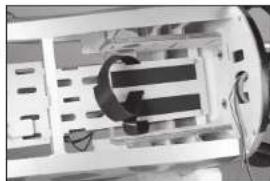
natural_image
Interior view of a mechanical device with internal components and wiring (no visible text or symbols)
natural_image
Interior view of an electronic device showing internal components and wiring (no visible text or symbols)natural_image
Close-up of a mechanical component with a tool inserted, showing a circular opening and a black handle (no visible text or symbols)
natural_image
Close-up of a mechanical component with a rod inserted, no visible text or symbols
natural_image
Close-up of a mechanical component with internal cavities and mounting holes (no visible text or symbols)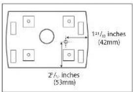
natural_image
Interior view of an electronic device with visible components and wiring (no text or symbols)
natural_image
Close-up of a hand holding a small object with a string-like mark, possibly a tool or marker (no visible text or symbols)
natural_image
Close-up of a mechanical component with bolt holes and mounting holes (no visible text or symbols)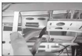
natural_image
Close-up of a hand holding a cable inserted into a rack of electronic equipment (no visible text or symbols)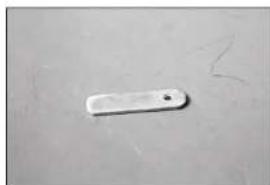
natural_image
Simple white rectangular object on a plain surface with faint handwritten marks (no text or symbols)natural_image
Close-up of hands holding a tool with visible mechanical components (no text or symbols)natural_image
Close-up of a mechanical assembly with no visible text or symbolsnatural_image
Close-up of a mechanical assembly with metallic components and wiring (no visible text or symbols)natural_image
Close-up of a mechanical assembly with wires and components, no visible text or symbolsnatural_image
Close-up of a mechanical assembly with a cylindrical component and connecting rods (no visible text or symbols)natural_image
Interior view of a vehicle cabin with seats and overhead structure (no visible text or symbols)natural_image
Interior view of a server rack with ventilation slots and cables (no visible text or labels)natural_image
Close-up of a mechanical assembly with circular components and a black housing (no visible text or symbols)natural_image
Close-up of a hand holding a small metallic object with a white base (no visible text or symbols)INSTALLATION DU RÉSERVOIR DE CARBURANT
natural_image
Close-up of two black cables with metallic connectors and white plastic caps (no text or symbols visible)natural_image
Close-up of a hand holding a small black object with a curved line, next to a white plastic container (no visible text or symbols)
natural_image
Close-up of a white plastic container with a black cable inserted (no visible text or symbols)
natural_image
Interior view of a storage or warehouse with a cow-shaped container and ladder (no visible text or symbols)natural_image
White electronic device with a black cable inserted, no visible text or symbols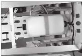
natural_image
Interior view of a computer case showing internal components like CPU, memory, and drive bays (no visible text or labels)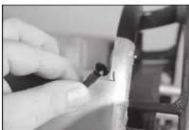
natural_image
Close-up of a hand holding a small black object, possibly a tool or device, with no visible text or symbols.
natural_image
Interior view of a warehouse or storage room with shelves and equipment (no visible text or symbols)
natural_image
Close-up of a mechanical assembly with metallic components and wiring (no visible text or symbols)natural_image
Close-up of a mechanical component with visible wiring and components (no text or symbols)INSTALLATION DU SYSTÈME PNEUMATIQUE DE RENTRÉE
natural_image
Close-up of a white cylindrical object with a metallic wire inserted, no visible text or symbols
natural_image
Close-up of a mechanical assembly with internal components (no visible text or symbols)
natural_image
Interior view of a mechanical assembly with cylindrical components and mounting brackets (no visible text or symbols)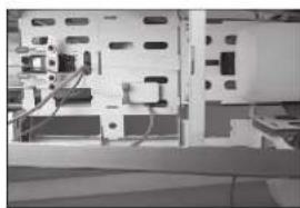
natural_image
Interior view of a computer setup with monitor, keyboard, and mouse (no visible text or labels)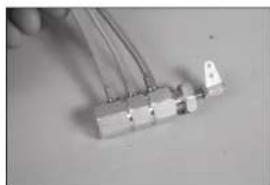
natural_image
Close-up of a small electronic component with wires and connectors (no visible text or symbols)natural_image
Close-up of a computer motherboard with visible circuitry and connectors (no text or symbols)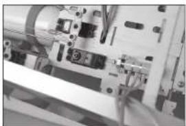
natural_image
Close-up of electronic components and wiring (no visible text or symbols)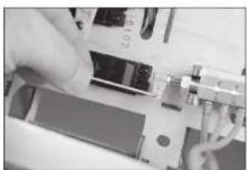
natural_image
Close-up of hands operating a mechanical device with no visible text or symbols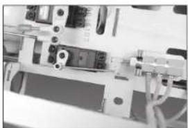
natural_image
Close-up of electronic components with visible wiring and connectors (no text or symbols)natural_image
Interior view of a computer interface with ports and connectors (no visible text or symbols)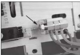
natural_image
Close-up of a mechanical device with an arrow pointing to a component (no visible text or symbols)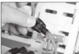
natural_image
Close-up of a hand inserting a small electronic component into a device (no visible text or symbols)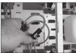
natural_image
Close-up of hands holding a coiled cable and connector on a computer motherboard (no visible text or symbols)natural_image
Interior view of an electronic device showing internal components and wiring (no visible text or symbols)INSTALLATION DU RÉCEPTEUR
natural_image
Interior view of an electronic device with visible circuitry and wiring (no text or symbols)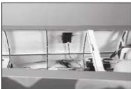
natural_image
Interior view of a room with shelves, equipment, and a wall-mounted device (no visible text or symbols)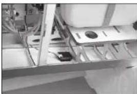
natural_image
Interior view of a mechanical or electrical enclosure with metal framing and internal components (no visible text or symbols)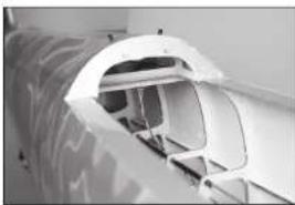
natural_image
Close-up of a white mechanical component with internal channels and mounting brackets (no visible text or symbols)INSTALLATION DU CAPOT ET DU CÔNE
natural_image
Close-up of a hand using a tool to cut a circular mechanical component with holes (no text or symbols visible)natural_image
Hand holding a metallic film reel with multiple holes (no text or symbols visible)natural_image
Close-up of hands holding a mechanical component, possibly a wheel or gear, with no visible text or symbols.natural_image
Close-up of a metallic mechanical component with a cylindrical housing and a metal rod inserted (no visible text or symbols)natural_image
Close-up of a metallic blade with four small holes, no visible text or symbols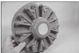
natural_image
Close-up of a hand holding a metallic gear or impeller with visible teeth and central bore (no text or symbols)
natural_image
Close-up of a metallic gear with multiple teeth and two arrows indicating specific features (no text or symbols)
natural_image
Close-up of a mechanical gear or wheel component with radial blades and central bore (no visible text or symbols)
natural_image
Close-up of a mechanical component with internal gear-like structure (no visible text or symbols)natural_image
Close-up of a mechanical component with metallic rods and a small rectangular block (no visible text or symbols)natural_image
Close-up of a mechanical component with visible gears and shafts (no text or symbols)natural_image
Close-up of a white and black patterned object with no visible text or symbolsnatural_image
Close-up of a hand holding a small object, possibly a tool or device, against a plain background (no visible text or symbols)natural_image
Close-up of hands using a pen to apply a small object on a white surface (no visible text or symbols)natural_image
Close-up of hands performing a sewing or stitching technique on a piece of paper (no visible text or symbols)
natural_image
Close-up of hands holding a pen writing on a white sheet (no visible text or symbols)
natural_image
Close-up of hands using a tool to adjust or install a small electronic component (no visible text or symbols)
natural_image
Close-up of a small electronic component with a grid-like structure, partially held by hands (no visible text or symbols)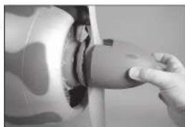
natural_image
Close-up of a hand pressing down on a car wheel rim (no visible text or symbols)CENTRE DE GRAVITÉ
DÉBATTEMENTS
CHECKLIST D'AVANT VOL
natural_image
Abstract geometric pattern with overlapping squares and a central dark square (no text or symbols)
natural_image
Abstract geometric composition with a central dark square containing an upward arrow and surrounding white rectangular fragments (no text or symbols)
natural_image
Interior ceiling view with a dark square label and white tape, no visible text or symbols
natural_image
Close-up of a hand holding a small object on a surface, with faint lines and a small mark visible (no text or symbols)
natural_image
Close-up of a silver computer case with a partially visible internal component (no text or symbols)natural_image
Medical device with a bowl and handle, no visible text or symbolsnatural_image
Interior view of a medical or laboratory device with mechanical components and tubing (no visible text or symbols)natural_image
Interior view of a stainless steel kitchen appliance with visible sink and door (no text or symbols)natural_image
Close-up of a metallic panel with a small rectangular cutout and wire, no visible text or symbolsnatural_image
Close-up of a metallic mechanical component with internal cavities and mounting holes (no visible text or symbols)natural_image
Interior view of a vehicle or industrial facility with machinery and structural elements (no visible text or symbols)natural_image
Close-up of a mechanical assembly with metallic components and wiring (no visible text or symbols)natural_image
Close-up of a metallic mechanical component with internal channels and a small inset showing a curved surface (no text or symbols visible)natural_image
Close-up of a hand holding a small black screw (no text or symbols visible)natural_image
Close-up of a mechanical assembly with a cylindrical component and mounting holes (no visible text or symbols)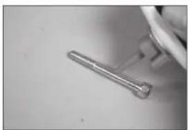
natural_image
Close-up of a metallic tool or tool on a surface, no visible text or symbols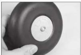
natural_image
Close-up of a hand holding a dark circular object with a central hole, possibly a knob or knob (no text or symbols visible)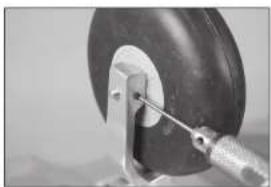
natural_image
Close-up of a mechanical clamp or bracket with a circular component and metal rod (no visible text or symbols)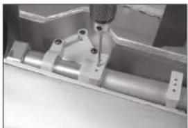
natural_image
Close-up of a mechanical assembly with metal components and a tool (no visible text or symbols)
natural_image
Close-up of a mechanical component with a precision tool inserted, no visible text or symbols
natural_image
Close-up of a metallic mechanical component with a white sheet and bolted base (no visible text or symbols)
natural_image
Close-up of a mechanical component with a metallic tool inserted into a white block (no visible text or symbols)
natural_image
Close-up of a metallic mechanical component with visible wheel and mounting holes (no text or symbols)natural_image
Close-up of hands using a tool to adjust or install a white strip on a metal surface (no visible text or symbols)natural_image
Close-up of a precision tool tip cutting through a metal bracket (no visible text or symbols)natural_image
Close-up of a metallic surface with a white panel and small black dots, no visible text or symbolsnatural_image
Close-up of a metallic mechanical joint or bracket with mounting holes and a vertical rod inserted (no visible text or symbols)natural_image
Close-up of a hand holding a metallic electronic device with a small electronic component (no visible text or symbols)natural_image
Close-up of a mechanical component with a pipe or seal, showing no visible text or symbolsnatural_image
Close-up of a hand holding a small white plastic component with a black square on top, against a plain background (no text or symbols visible)natural_image
Close-up of a metallic mechanical component with mounting holes and a small inset detail (no visible text or symbols)natural_image
Close-up of hands using a pen to adjust or install electronic components (no visible text or symbols)natural_image
Close-up of a metallic mechanical component with mounting holes and a reflective surface (no visible text or symbols)natural_image
Hand holding a circular object with a small droplet, possibly a button or knob (no text or symbols visible)
natural_image
Close-up of a circular mechanical component with a central square hole (no visible text or symbols)natural_image
Close-up of a hand holding a small metallic object with a white tag, partially visible against a plain background (no text or symbols)
natural_image
Close-up of a hand holding a small metallic object (no visible text or symbols)
natural_image
Close-up of a metallic surface with a small mark and diagonal line, no visible text or symbols
natural_image
Close-up of a hand holding a knife, showing a slightly cut blade (no text or symbols visible)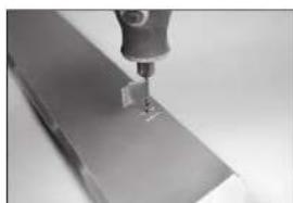
natural_image
Close-up of a precision tool tip interacting with a metallic surface (no visible text or symbols)natural_image
Close-up of a metallic object with a small white tool inserted into a dark square base (no visible text or symbols)natural_image
Close-up of a hand holding a small electronic component (no visible text or symbols)natural_image
Close-up of a hand holding a small white tool interacting with a dark surface (no visible text or symbols)natural_image
Close-up of hands holding a small white plastic object with a string (no visible text or symbols)natural_image
Close-up of a hand holding a small object with a metallic clip, possibly part of a device or tool (no visible text or symbols)natural_image
Close-up of a metallic mechanical component with a curved handle, mounted on a dark base (no visible text or symbols)INCERNIERAMENTO DEGLI ALETTONI
natural_image
Close-up of a hand holding a small white object with a pointed tip, possibly a tool or component (no visible text or symbols)natural_image
Close-up of hands holding a metal object with a small hole, no visible text or symbols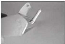
natural_image
Close-up of a hand holding a small white tool, possibly a pen or clip, against a plain background (no text or symbols visible)natural_image
Close-up of a hand holding a small metallic object with a screw, against a plain background (no text or symbols visible)natural_image
Close-up of a hand holding a metallic cylindrical object with two small protrusions inserted (no text or symbols visible)natural_image
Close-up of a hand holding a thin wire with a small white object, possibly a medical or technical component (no visible text or symbols)natural_image
Close-up of hands using a tool to apply material or tools on a metal surface (no visible text or symbols)natural_image
Close-up of a textured surface with a circular hole, possibly a device or material sample (no visible text or symbols)natural_image
Close-up of hands holding a thin, thin wire or filament (no text or symbols visible)natural_image
Close-up of a hand holding a pen over a metallic surface (no visible text or symbols)natural_image
Close-up of hands holding a rectangular object with a circular hole, possibly part of a mechanical or architectural component (no visible text or symbols)natural_image
Close-up of a hand using tweezers to apply a small mechanical component (no visible text or symbols)natural_image
Close-up of a hand holding a small black device with a white handle, attached to a wire (no visible text or symbols)natural_image
Close-up of two black electrical connectors with white wires, no visible text or symbolsnatural_image
Close-up of a hand holding a small electronic device with a metallic rod (no visible text or symbols)natural_image
Close-up of a hand inserting a small electronic component into a device (no visible text or symbols)natural_image
Close-up of hands holding wires inside an open electrical outlet (no visible text or symbols)natural_image
Close-up of a white mechanical component with internal compartments and a dark clip (no visible text or symbols)natural_image
Interior view of a small electronic device with visible circuitry and components (no text or symbols)natural_image
Close-up of a mechanical assembly with a bracket and housing (no visible text or symbols)
natural_image
Close-up of a metallic tool or fixture on a tiled floor (no visible text or symbols)INCERNIERAMENTO DEI FLAP
natural_image
Simple line drawing of a fish head with an arrow pointing to it (no text or symbols)
natural_image
Close-up of a metallic blade with a small circular feature, no visible text or symbols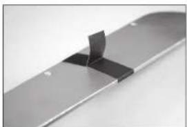
natural_image
Close-up of a metallic mechanical component with a folded section (no visible text or symbols)natural_image
Close-up of a hand holding a thin metal rod with a small protrusion, against a plain background (no text or symbols visible)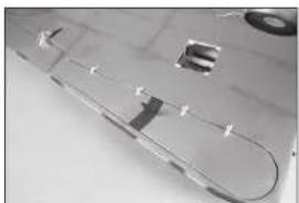
natural_image
Close-up of a metallic electronic component with internal slots and a curved line (no visible text or symbols)natural_image
Close-up of a hand holding a white object with white markings, against a plain background (no text or symbols visible)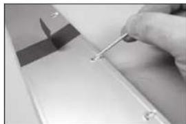
natural_image
Close-up of a hand holding a small metal rod inserted into a flat surface, with no visible text or symbols.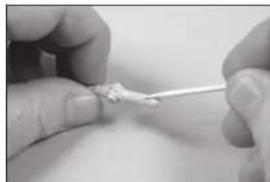
natural_image
Close-up of hands holding a small object with a string, no visible text or symbols
natural_image
Close-up of a hand holding a pen tip, no visible text or symbols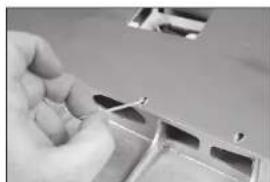
natural_image
Close-up of a hand using a tool to cut or mark a metal component (no visible text or symbols)natural_image
Close-up of a hand using a tool to cut or install a metallic component, no visible text or symbols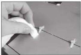
natural_image
Close-up of a hand holding a small white object on a surface, with no visible text or symbols.natural_image
Close-up of a hand holding a small electronic component with wires (no visible text or symbols)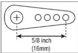
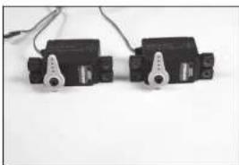
natural_image
Two black mechanical components with metallic fittings and wiring, placed on a plain white surface (no text or symbols visible)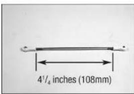
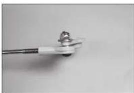
natural_image
Close-up of a small electronic component with metallic leads and a small metallic connector (no visible text or symbols)natural_image
Close-up of a white mechanical component with a metallic rod and circular end (no text or symbols visible)natural_image
Interior view of an open electrical enclosure with internal components (no visible text or symbols)natural_image
Interior view of a small electronic device with an open socket and internal components (no visible text or symbols)natural_image
Metallic electronic component with curved internal structure and mounting holes (no visible text or symbols)natural_image
Close-up of a mechanical component with a central knob and flanges (no visible text or symbols)natural_image
Black-and-white photo of a mechanical device with no visible text or symbolsnatural_image
Black-and-white photo of a mechanical device mounted on a wall, no visible text or symbolsnatural_image
Metallic plastic boat hull on a flat surface, no visible text or symbolsnatural_image
Metallic electronic component with rounded edges and a small inset component (no visible text or symbols)
natural_image
Close-up of a white train or high-speed train with multiple windows and side compartments (no visible text or symbols)natural_image
Close-up of a transparent plastic sheet with visible surface markings and a circular object on top (no text or symbols)INSTALLAZIONE DEI SERBATOI SGANCIABILI
natural_image
Metal mechanical bracket with two side slots and a flat top (no text or symbols visible)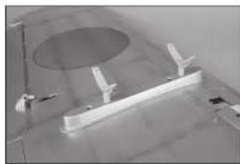
natural_image
Interior view of a room with a circular ceiling light and a wooden beam supported by two metal fixtures (no visible text or symbols)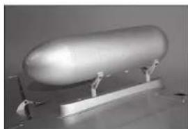
natural_image
Exterior view of a modern office building (no signage)INSTALLAZIONE DELLO STABILIZZATORE
natural_image
Close-up of a hand holding a small white object with a pointed tip, against a patterned surface (no text or symbols visible)natural_image
Close-up of a metallic object with abstract patterns and a central hole (no visible text or symbols)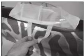
natural_image
Close-up of hands holding a transparent plastic bag over a patterned fabric (no visible text or symbols)natural_image
Close-up of metallic mechanical components with a tool inserted (no visible text or symbols)natural_image
Close-up of a metallic mechanical component with circular cutouts and a pointed tip (no visible text or symbols)natural_image
Close-up of a hand using a tool to cut or mark a metallic component (no visible text or symbols)natural_image
Close-up of a textured, patterned object with no visible text or symbolsnatural_image
Close-up of a pen tip interacting with a mechanical component (no visible text or symbols)natural_image
Close-up of a metallic bracket with four circular holes, no visible text or symbolsnatural_image
Close-up of a hand holding a metallic tool interacting with a curved surface (no visible text or symbols)natural_image
Close-up of a rolled-up fabric with abstract wavy patterns (no text or symbols visible)natural_image
Close-up of a hand holding a pen, writing on paper with faint background patterns (no visible text or symbols)natural_image
Architectural floor plan view showing room layouts and structural elements (no text or labels visible)natural_image
Close-up of a hand holding a small white object on a dark surface, with no visible text or symbols.natural_image
Close-up of a hand holding a ruler measuring a metal object (no visible text or symbols)natural_image
Close-up of a gloved hand holding a small object over a patterned surface (no visible text or symbols)natural_image
Close-up of a mechanical component with a tool applying material to a surface (no visible text or symbols)natural_image
Close-up of a hand holding a pen-like tool, with no visible text or symbolsnatural_image
Close-up of metallic mechanical components with no visible text or symbols
natural_image
Exterior view of a modern office building (no signage)
natural_image
Close-up of a metallic airplane with visible propellers and branding (no readable text or symbols)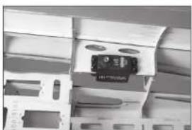
natural_image
Close-up of a mechanical assembly with a central component and mounting holes (no visible text or symbols)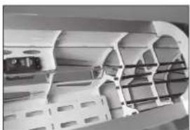
natural_image
Interior architectural view of a modern building with curved structural elements (no visible text or symbols)natural_image
Abstract grayscale image with vertical striped patterns and layered textures, no visible text or symbols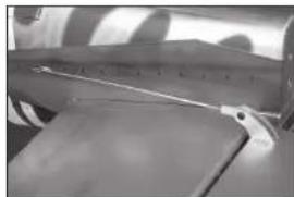
natural_image
Close-up of a mechanical component with a ruler and flange (no visible text or symbols)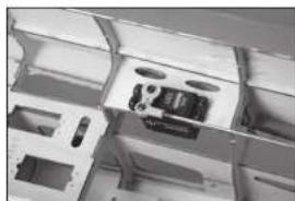
natural_image
Interior view of a technical enclosure or enclosure with internal compartments and no visible text or symbols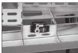
natural_image
Close-up of a mechanical component with a metallic housing and mounting holes (no visible text or symbols)
natural_image
Close-up of a metallic mechanical component with a curved edge and flange (no visible text or symbols)natural_image
Close-up of a handheld electronic device with metallic pins and a patterned cover (no visible text or symbols)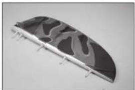
natural_image
Curved metallic object with abstract wavy patterns, mounted on a flat surface (no text or symbols visible)
natural_image
Close-up of a butterfly wing with black and white patterned wings (no text or symbols visible)INSTALLAZIONE DEL LEVERAGGIO DEL TIMONE
natural_image
Close-up of an electronic circuit board with visible components and wiring (no readable text or symbols)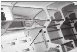
natural_image
Interior view of an automotive chassis frame with structural ribs and mounting holes (no visible text or symbols)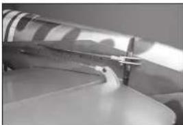
natural_image
Close-up of a metallic tool tip with a small protrusion, possibly part of a mechanical or architectural component (no visible text or symbols)
natural_image
Close-up of an electronic circuit board with connectors and components (no visible text or symbols)
natural_image
Two metallic tool holders with handles, no visible text or symbolsnatural_image
Close-up of a mechanical clamp or bracket component with two handles and a central handle (no text or symbols visible)
natural_image
Close-up of an electronic circuit board with connectors and components (no visible text or symbols)natural_image
Hand holding a small black object with a white circular hole, against a plain background (no text or symbols visible)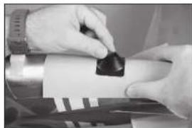
natural_image
Close-up of hands holding a small black object over a white surface, possibly a mechanical or electronic component (no visible text or symbols)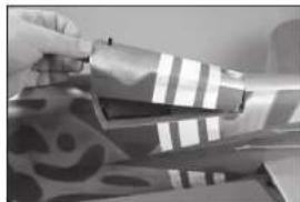
natural_image
Close-up of hands handling a patterned fabric or textile with striped and polka-dot designs (no visible text or symbols)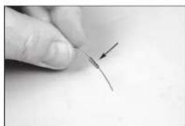
natural_image
Close-up of a finger pointing to a thin, curved wire or filament (no text or symbols visible)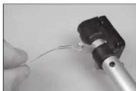
natural_image
Close-up of a hand holding a small wire or cable attached to a mechanical component (no visible text or symbols)natural_image
Close-up of a hand holding a small metallic tool with a black connector (no visible text or symbols)
natural_image
Close-up of a mechanical lever component with metallic shaft and clamped joints (no visible text or symbols)natural_image
Five black plastic screwdrivers arranged on a plain white surface (no text or symbols visible)
natural_image
Close-up of a mechanical assembly with metal components and a cylindrical shaft (no visible text or symbols)natural_image
Close-up of a transparent cylindrical mechanical component with internal cavities (no visible text or symbols)natural_image
Close-up of hands installing or adjusting a mechanical component with a tool (no visible text or symbols)
natural_image
Close-up of a computer motherboard with a hand holding a cable and a pen inserted, no visible text or symbols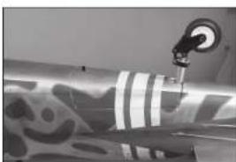
natural_image
Close-up of a mechanical component with a metallic hook and striped pattern, no visible text or symbols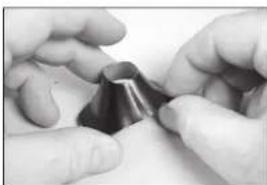
natural_image
Close-up of hands holding a metallic object with a pointed tip (no visible text or symbols)natural_image
Close-up of a robotic arm operating on a cylindrical mechanical component (no visible text or symbols)natural_image
Close-up of a mechanical device with gauges and a pointer (no visible text or symbols)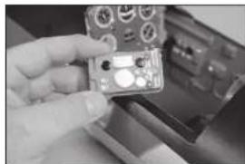
natural_image
Close-up of a hand holding a small electronic device with control knobs and buttons (no visible text or symbols)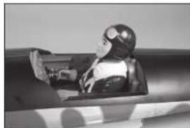
natural_image
Black-and-white photo of a person in a futuristic helmet and gear, seated in a vehicle (no visible text or symbols)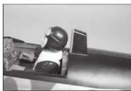
natural_image
Close-up of a mechanical component with a helmet and gear assembly (no visible text or symbols)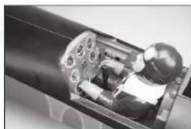
natural_image
Cross-sectional view of a mechanical device showing internal components and housing (no visible text or symbols)natural_image
Close-up of a metallic structural component with a triangular cutout and flange (no visible text or symbols)natural_image
Close-up of a hand holding a small metallic object with grid-like surfaces (no visible text or symbols)natural_image
Model of a futuristic jet aircraft with cockpit and crew visible (no text or symbols)natural_image
Close-up of a mechanical component with a tool inserted, showing a circular housing and mounting holes (no text or symbols visible)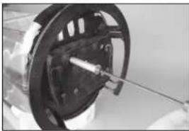
natural_image
Close-up of a mechanical component with a rod inserted, no visible text or symbols
natural_image
Close-up of a mechanical component with internal cavities and mounting holes (no visible text or symbols)natural_image
Close-up of a mechanical component with internal components and mounting brackets (no visible text or symbols)natural_image
Close-up of a mechanical component with a star-shaped base and metallic shaft (no visible text or symbols)natural_image
Close-up of a mechanical assembly with gears and shafts (no visible text or symbols)natural_image
Interior view of a computer room showing a computer with cables and a small electronic device (no visible text or symbols)natural_image
White plastic electronic component with two black rectangular strips, no visible text or symbolsnatural_image
Close-up of two metallic electronic components with wires, no visible text or symbolsnatural_image
Close-up of a white rectangular device with black bands and a black strap, no visible text or symbols.
natural_image
Interior view of a mechanical device with internal components and wiring (no visible text or symbols)
natural_image
Interior view of an electronic device showing internal components and wiring (no visible text or symbols)INSTALLAZIONE DEL MOTORE A BENZINA
natural_image
Close-up of a mechanical component with a tool inserted, showing a circular opening and a black handle (no visible text or symbols)natural_image
Interior view of an electronic device showing internal components and wiring (no visible text or symbols)
natural_image
Close-up of a hand holding a small object with a string, possibly a tool or marker (no visible text or symbols)
natural_image
Close-up of a metallic mechanical component with bolt holes and mounting holes (no visible text or symbols)
natural_image
Close-up of a hand holding a tool interacting with server racks (no visible text or symbols)
natural_image
Simple white rectangular object on a plain surface with faint markings (no text or symbols)natural_image
Close-up of a mechanical component with a rod inserted into a housing (no visible text or symbols)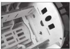
natural_image
Close-up of a mechanical component with internal cavities and mounting holes (no visible text or symbols)
natural_image
Close-up of hands holding a tool with visible mechanical components (no text or symbols)natural_image
Close-up of a mechanical assembly with no visible text or symbolsnatural_image
Close-up of a mechanical assembly with metallic components and wiring (no visible text or symbols)natural_image
Close-up of a mechanical assembly with wires and components, no visible text or symbolsnatural_image
Close-up of a mechanical device with internal components and wiring (no visible text or symbols)natural_image
Interior view of a vehicle cabin or garage with visible seats and structural beams (no text or symbols)natural_image
Interior view of a server rack with ventilation slots and cables (no visible text or symbols)natural_image
Close-up of a mechanical assembly with circular components and a black housing (no visible text or symbols)natural_image
Close-up of a hand holding a small metallic object with a white base (no visible text or symbols)natural_image
Close-up of two black cables with metallic connectors and white plastic caps (no text or symbols visible)natural_image
Close-up of a hand holding a small black object with a curved line, next to a white plastic container (no visible text or symbols)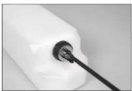
natural_image
Close-up of a white plastic container with a black cable inserted into the neck (no visible text or symbols)
natural_image
Interior view of a storage or warehouse with a cow-shaped container and ladder (no visible text or symbols)natural_image
White electronic device with a black cable inserted, no visible text or symbols
natural_image
Interior view of a computer room showing internal components and wiring (no visible text or symbols)
natural_image
Close-up of a hand holding a small black object, possibly a tool or device, with no visible text or symbols.
natural_image
Interior view of a dormitory room with bunk beds and a person standing near the ceiling (no visible text or symbols)
natural_image
Close-up of a mechanical assembly with metallic components and a central component (no visible text or symbols)natural_image
Close-up of a mechanical component with visible wiring and housing (no text or symbols)natural_image
Close-up of a white cylindrical object with a metallic rod inserted, no visible text or symbols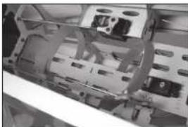
natural_image
Close-up of a mechanical assembly with internal components (no visible text or symbols)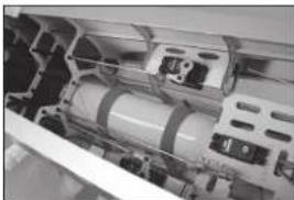
natural_image
Close-up of internal mechanical components, possibly a battery or motor assembly (no visible text or symbols)
natural_image
Interior view of an electronic device with visible circuitry and components (no text or symbols)natural_image
Close-up of a small electronic component with wires and a small labeled part (no visible text or symbols)natural_image
Close-up of electronic components and wiring (no visible text or symbols)
natural_image
Interior view of a medical or laboratory equipment setup with control panels and tubing (no visible text or symbols)natural_image
Close-up of a computer motherboard with visible circuit boards and a mechanical component (no text or symbols)natural_image
Close-up of a mechanical device with a small component and wiring (no visible text or symbols)natural_image
Close-up of electronic components and wiring (no visible text or symbols)natural_image
Close-up of a hand inserting a black plastic component into a circuit board (no visible text or symbols)natural_image
Close-up of a hand holding a small electronic device with visible ports and wiring (no text or symbols)natural_image
Close-up of hands holding a coiled cable and connector on an electronic device (no visible text or symbols)natural_image
Interior view of an electronic device showing internal components and wiring (no visible text or symbols)natural_image
Interior view of an electronic device with visible circuitry and wiring (no text or symbols)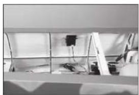
natural_image
Interior view of a room with shelves, electrical equipment, and a wall-mounted power supply (no visible text or symbols)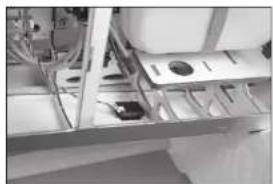
natural_image
Interior view of a room with metal shelving and wall-mounted equipment (no visible text or symbols)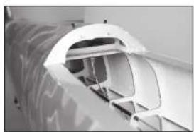
natural_image
Close-up of a white aircraft fuselage with visible structural details (no text or symbols)natural_image
Close-up of a hand using a tool to cut a circular mechanical component with holes (no text or symbols visible)
natural_image
Hand holding a metallic film reel with multiple holes (no text or symbols visible)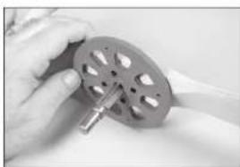
natural_image
Close-up of hands holding a metallic tool next to a circular mechanical component (no visible text or symbols)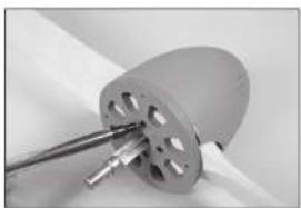
natural_image
Close-up of a metallic mechanical component with a cylindrical housing and a rod inserted (no visible text or symbols)natural_image
Close-up of a metallic blade with four small holes, no visible text or symbols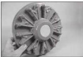
natural_image
Close-up of a metallic gear or impeller with visible teeth and central bore (no text or symbols)
natural_image
Close-up of a metallic gear or cutting edge with internal teeth and two black arrows indicating specific features (no text or symbols present)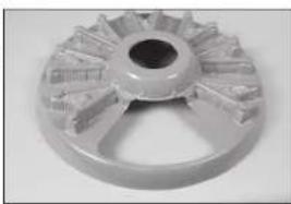
natural_image
Close-up of a metallic mechanical component with radial grooves and central bore (no visible text or symbols)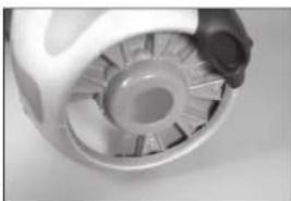
natural_image
Close-up of a mechanical component with a central gear-like structure and surrounding blades (no visible text or symbols)natural_image
Close-up of a mechanical component with metallic rods and a small rectangular block (no visible text or symbols)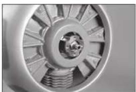
natural_image
Close-up of a mechanical component with visible gears and shafts (no text or symbols)
natural_image
Close-up of a white and black patterned object with no visible text or symbols
natural_image
Close-up of a hand holding a small object, possibly a tool or device, against a plain background (no visible text or symbols)
natural_image
Close-up of hands using a pen to apply a small object on a white surface (no visible text or symbols)natural_image
Close-up of hands performing a sewing or stitching technique on a piece of paper (no visible text or symbols)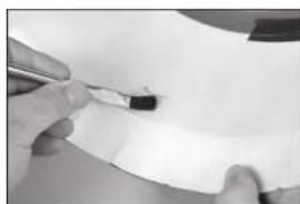
natural_image
Close-up of hands holding a pen writing on a white sheet (no visible text or symbols)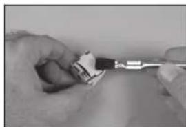
natural_image
Close-up of hands using a tool to adjust or install a small electronic component (no visible text or symbols)
natural_image
Close-up of a small electronic component with a grid-like structure, partially held by fingers (no visible text or symbols)
natural_image
Close-up of a hand pressing down on a car wheel rim (no visible text or symbols)BARICENTRO (CG)
CORSE DEI COMANDI
SPECIFICATIONS • SPEZIFIKATIONEN • SPÉCIFICATIONS • SPECIFICHE
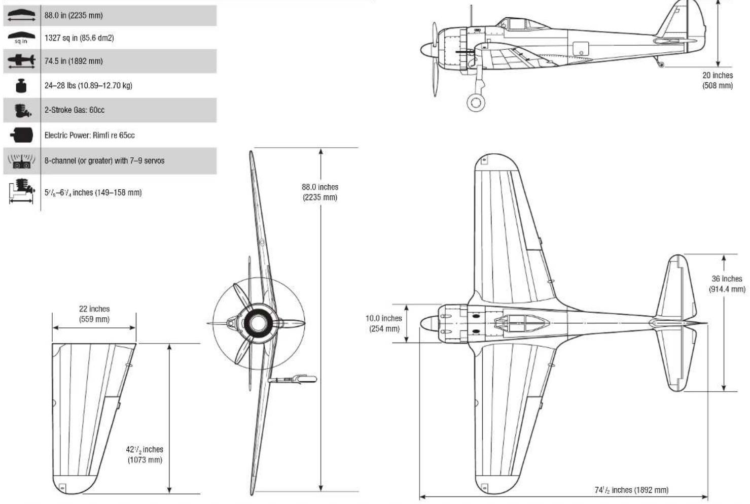
88.0 in (2235 mm)
1327 sq in (85.6 dm2)
74.5 in (1892 mm)
24–28 lbs (10.89–12.70 kg)
2-Stroke Gas: 60cc
Electric Power: Rimfi re 65cc
8-channel (or greater) with 7–9 servos
5^/8-6^/4 inches (149–158 mm)
HANGAR 9®
© 2019 Horizon Hobby, LLC.
Hangar 9, UltraCote, Evolution, AS3X and the Horizon Hobby logo are trademarks or registered trademarks of Horizon Hobby, LLC.
The Spektrum trademark is used with permission of Bachmann Industries, Inc. All other trademarks, service marks and logos are the property of their respective owners.
Created 07/19 60728 HAN4720