Ultra Stick 30cc - Remote control toy Hangar 9 - Free user manual and instructions
Find the device manual for free Ultra Stick 30cc Hangar 9 in PDF.
Frequently Asked Questions - Ultra Stick 30cc Hangar 9
User questions about Ultra Stick 30cc Hangar 9
0 question about this device. Answer the ones you know or ask your own.
Ask a new question about this device
Download the instructions for your Remote control toy in PDF format for free! Find your manual Ultra Stick 30cc - Hangar 9 and take your electronic device back in hand. On this page are published all the documents necessary for the use of your device. Ultra Stick 30cc by Hangar 9.
USER MANUAL Ultra Stick 30cc Hangar 9
natural_image
Black-and-white photo of a small airplane in flight, showing wing and tail panels with no visible text or symbols.Instruction Manual
Bedienungsanleitung
All instructions, warranties and other collateral documents are subject to change at the sole discretion of Horizon Hobby, LLC. For up-to-date product literature, visit horizonhobby.com and click on the support tab for this product. The following terms are used throughout the product literature to indicate various levels of potential harm when operating this product:
Meaning of Special Language
NOTICE: Procedures, which if not properly followed, create a possibility of physical property damage AND a little or no possibility of injury.
CAUTION: Procedures, which if not properly followed, create the probability of physical property damage AND a possibility of serious injury.
WARNING: Procedures, which if not properly followed, create the probability of property damage, collateral damage, and serious injury OR create a high probability of superficial injury.
WARNING: Read the ENTIRE instruction manual to become familiar with the features of the product before operating. Failure to operate the product correctly can result in damage to the product, personal property and cause serious injury.
This is a sophisticated hobby product. It must be operated with caution and common sense and requires some basic mechanical ability. Failure to operate this Product in a safe and responsible manner could result in injury or damage to the product or other property. This product is not intended for use by children without direct adult supervision. Do not attempt disassembly, use with incompatible components or augment product in any way without the approval of Horizon Hobby, LLC. This manual contains instructions for safety, operation and maintenance. It is essential to read and follow all the instructions and warnings in the manual, prior to assembly, setup or use, in order to operate correctly and avoid damage or serious injury.
AGE RECOMMENDATION: NOT FOR CHILDREN UNDER 14 YEARS. THIS IS NOT A TOY.
□ USING THE MANUAL
This manual is divided into sections to help make assembly easier to understand.
□ SAFETY WARNINGS AND PRECAUTIONS
Read and follow all instructions and safety precautions before use. Improper use can result in fire, serious injury and damage to property.
Components
Use only with compatible components. Should any compatibility questions exist, please refer to the product instructions, component instructions or contact the appropriate Horizon Hobby office.
Flight
Fly only in open areas to ensure safety. It is recommended fl ying be done at radio control fl ying fi elds. Consult local ordinances before choosing a fl ying location.
Propeller
Keep loose items that can become entangled in the propeller away from the prop. This includes loose clothing or other objects such as pencils and screwdrivers. Keep your hands away from the propeller as injury can occur.
Batteries
Always follow the manufacturer's instructions when using and disposing of any batteries. Mishandling of Li-Po batteries can result in fi re causing serious injury and damage.
Small Parts
This kit includes small parts and should not be left unattended near children as choking and serious injury could result.
SAFE OPERATING RECOMMENDATIONS
- Inspect your model before every flight to ensure it is airworthy.
- Be aware of any other radio frequency user who may present an interference problem.
• Always be courteous and respectful of other users in your selected flight area. - Choose an area clear of obstacles and large enough to safely accommodate your flying activity.
- Make sure this area is clear of friends and spectators prior to launching your aircraft.
- Be aware of other activities in the vicinity of your flight path that could cause potential conflict.
- Carefully plan your flight path prior to launch.
- Abide by any and all established AMA National Model Aircraft Safety Code.
BEFORE STARTING ASSEMBLY
- Remove parts from bag.
- Inspect fuselage, wing panels, rudder and stabilizer for damage.
- If you find damaged or missing parts, contact your place of purchase.
If you find any wrinkles in the covering, use a heat gun (HAN100) and covering glove (HAN150) or covering iron (HAN101) with a sealing iron sock (HAN141) to remove them. Use caution while working around areas where the colors overlap to prevent separating the colors.
- Charge transmitter and receiver batteries.
• Center trims and sticks on your transmitter. - For a computer radio, create a model memory for this particular model.
- Bind your transmitter and receiver, using your radio system's instructions.
IMPORTANT: Rebind the radio system once all control throws are set. This will keep the servos from moving to their endpoints until the transmitter and receiver connect. It will also guarantee the servo reversal settings are saved in the radio system.
HINWEIS
During assembly, we recommend resting the parts on a soft surface such as a soft towel to help prevent denting the sheeting.
□ REMOVING WRINKLES
The covering of your model may develop wrinkles during shipping and will require the use of a heat gun (HAN100) and covering glove (HAN150) or covering iron (HAN101) with a sealing iron sock (HAN141) to remove them. Use caution while working around areas where the colors overlap to prevent separating the colors. Avoid using too much heat, which could separate the colors. Placing a cool damp cloth on adjacent colors will also help in preventing the separation of the colors while removing wrinkles.
□ TRANSPORTATION AND STORAGE
When transporting and storing your model, you will need a minimum of 80 inches (2m) in length, and 18 inches (46cm) in height to accommodate the size of the fuselage. We also recommend the use of a wing bag and stabilizer bags to help protect these surfaces during transport and storage. The control horns and linkages can also cause damage to nearby surfaces even when placed in storage bags. Always place surfaces so the tops are together to prevent damage from the control horns and linkages.
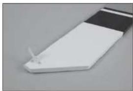
☐ OPTIONAL FLOAT INSTALLATION
When installing the recommended fl oats on your Ultra Stick 30cc, make sure to use the optional fl oat strut set HAN236519. These struts are longer than those in the recommended fl oat kit and provide the necessary propeller clearance for water operation. When installing the struts, make sure to use the longer struts at the front, and the shorter struts at the rear. This is necessary to obtain the correct angle between the wing and fl oats.
HINWEISE ZUM BAU
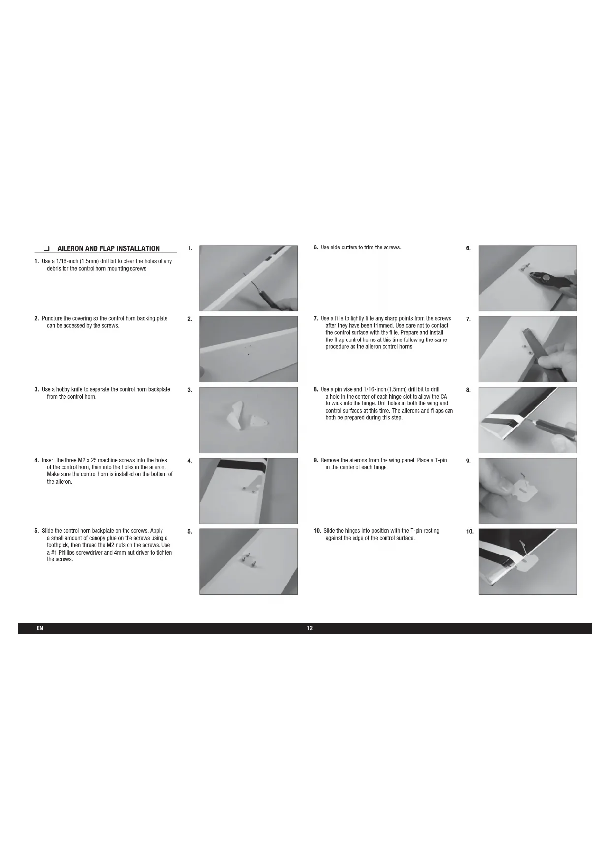
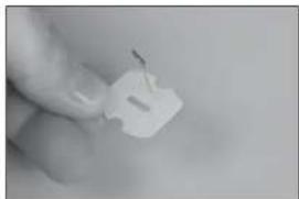
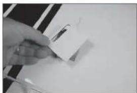
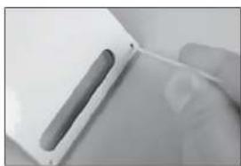
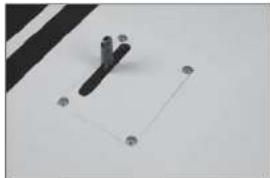
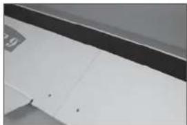
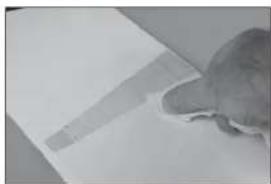
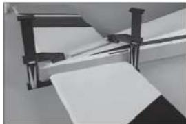
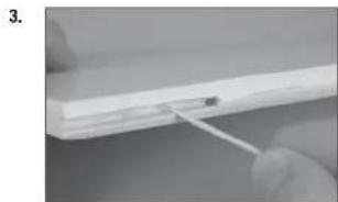
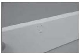
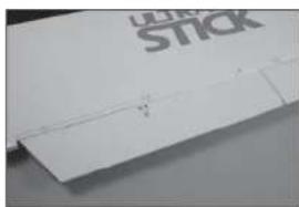
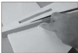
- Use a 1/16-inch (1.5mm) drill bit to clear the holes of any debris for the control horn mounting screws.
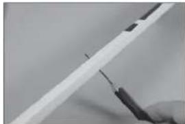
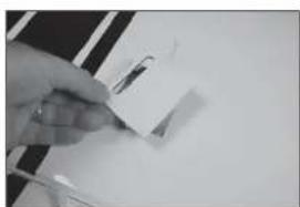
- Puncture the covering so the control horn backing plate can be accessed by the screws.
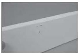
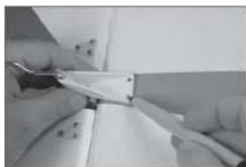
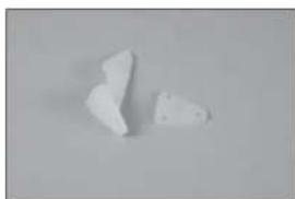
- Use a hobby knife to separate the control horn backplate from the control horn.
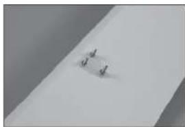
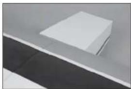
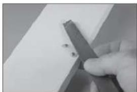
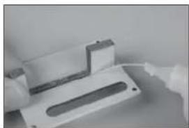
- Insert the three M2 x 25 machine screws into the holes of the control horn, then into the holes in the aileron. Make sure the control horn is installed on the bottom of the aileron.
- Slide the control horn backplate on the screws. Apply a small amount of canopy glue on the screws using a toothpick, then thread the M2 nuts on the screws. Use a #1 Phillips screwdriver and 4mm nut driver to tighten the screws.
1.
natural_image
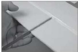
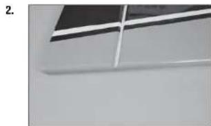
Close-up of a hand holding a tool next to a white rectangular object (no visible text or symbols)2.
natural_image
Close-up of a white rectangular object with a small mark on the surface (no visible text or symbols)3.
natural_image
Two irregular white fragments on a plain gray background (no text or symbols)4.

natural_image
Exterior view of a modern office building (no signage)5.
natural_image
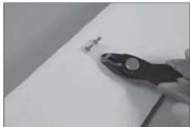
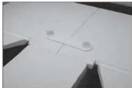
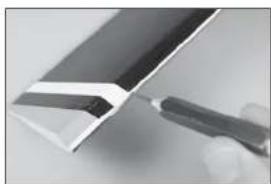
Close-up of a small metallic object on a plain surface (no visible text or symbols)- Use side cutters to trim the screws.
- Use a file to lightly file any sharp points from the screws after they have been trimmed. Use care not to contact the control surface with the file. Prepare and install the flap control horns at this time following the same procedure as the aileron control horns.
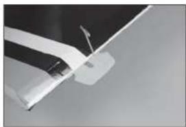
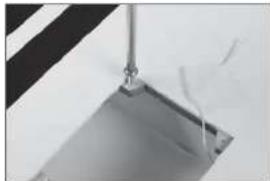
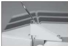
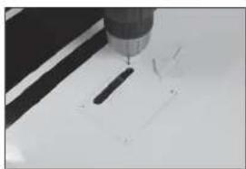
- Use a pin vise and 1/16-inch (1.5mm) drill bit to drill a hole in the center of each hinge slot to allow the CA to wick into the hinge. Drill holes in both the wing and control surfaces at this time. The ailerons and flaps can both be prepared during this step.
- Remove the ailerons from the wing panel. Place a T-pin in the center of each hinge.
- Slide the hinges into position with the T-pin resting against the edge of the control surface.
6.
natural_image
Close-up of a gloved hand holding a pliers near a small object on a white surface (no text or symbols visible)7.

natural_image
Close-up of a hand holding a metal cutting tool over a white surface (no text or symbols visible)8.

natural_image
Close-up of a metallic tool interacting with a white panel or sheet metal (no visible text or symbols)9.
natural_image
Close-up of a hand holding a small white plastic clip (no text or symbols visible)10.
natural_image
Close-up of a white aircraft wing with a visible propeller and arrow (no text or symbols)- Repeat the previous steps to install all four of the aileron hinges.
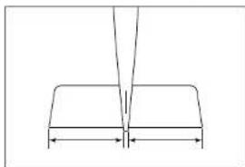
- Fit the alleron to the wing by inserting the hinges into the slots in the wing.
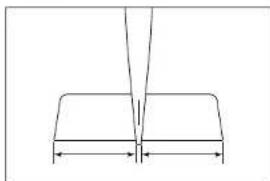
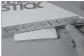
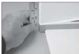
- Check that there is a slight gap between the wing and the end of the aileron. Use a thin ruler (or similar) as a spacer so both the left and right ailerons have the same size gap.
- Apply thin CA to the top and bottom of each hinge. Once the CA cures, gently pull on the fixed surface and control surface to make sure the hinges are glued securely. If not, apply additional CA to secure each of the hinges.
- Prepare the three hinges for the flap and place it into position on the wing.
11.
natural_image
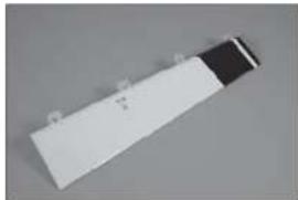
White rectangular object with a black top, possibly a battery or scanner (no visible text or symbols)12.
natural_image
Close-up of a white rectangular object with a small mark and a faint horizontal line, placed on a dark surface (no text or symbols visible)13.

natural_image
Close-up of a hand holding a pen, with a black-and-white flag patch partially visible (no text or symbols)14.

natural_image
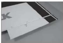
Close-up of a hand holding a dark rectangular object with a white cross-shaped mark, against a plain background (no text or symbols visible)15.
natural_image
Close-up of a white plastic sheet with a visible crack, no text or symbols present.- Check the gap between the fl ap and aileron. Use a thin ruler (or similar) as a spacer so the gap between the left and right ailerons and fl aps are the same. Glue the hinges for the fl aps using thin CA. Once the CA cures, gently pull on the fi xed surface and control surface to make sure the hinges are glued securely. If not, apply additional CA to secure each of the hinges.
□ AILERON AND FLAP SERVO INSTALLATION
- Remove the aileron servo hatch from the wing. Make sure to keep the string taped to the wing so it doesn't fall into the wing.
- Check that the servo mount is glued securely to the servo cover. If the mount is not secure, use a small amount of medium CA or epoxy to make sure the mount is securely fastened to the servo cover.
- Remove the aileron and fl ap cover from the wing. Use a toothpick to puncture the covering to locate the holes for the aileron and fl ap cover screws.
- Place the aileron and fl ap cover into position. Use a drill and 5/32-inch (2mm) drill bit to drill the holes in the servo cover mounts.
16.
natural_image
Close-up of a hand holding a white sheet with a pen, no visible text or symbols1.
natural_image
Close-up of a hand holding a small object with a ruler, against a plain white background (no visible text or symbols)2.

natural_image
Close-up of a white plastic electronic component with a slot and mounting holes (no visible text or symbols)3.
natural_image
Close-up of a hand holding a white plastic object with a slot, no visible text or symbols4.

natural_image
Close-up of a precision tool tip cutting a white surface with a black tool (no text or symbols visible)- Thread an M3 x 15 self-tapping screw into each of the holes in the aileron and flap servo cover mounting holes. Remove the screws before proceeding.
- Apply a small amount of thin CA to harden the threads made in the previous step. Allow the CA to fully cure before installing the aileron servo cover.
- Install the grommets and brass eyelets in the servos. Follow any instructions included with the servo. Prepare both flap and aileron servos at this time.
- Fit the servo between the servo mounting tabs in the aileron servo tray. The servo arm will be centered in the slot. Mark the locations for the servo mounting screws using a pencil, then remove the servo.
-
Use a drill and a 1/16-inch (1.5mm) drill bit to drill the holes for the servo mounting screws in the locations marked in the previous step. Use a 2mm hex wrench to thread a servo mounting screw into each of the holes in the alleron servo mounting holes. Remove the screws, then apply a small amount of thin CA to harden the threads.
-
natural_image
Close-up of a metallic object with a vertical rod and rectangular base, no visible text or symbols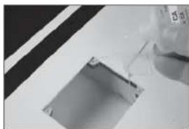
natural_image
Close-up of a glass bottle pouring liquid into a square pipe (no text or symbols visible)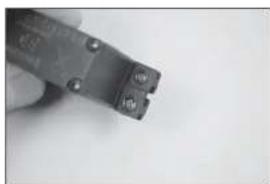
natural_image
Close-up of a small black electrical component with two terminals and mounting holes, held in hand (no visible text or symbols)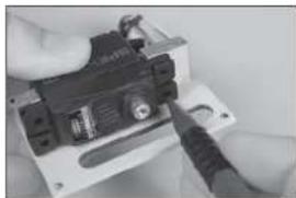
natural_image
Close-up of hands holding a small electronic device with a screwdriver (no visible text or symbols)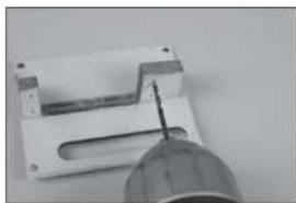
natural_image
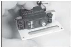
Close-up of a mechanical component with a tool inserted into a slot (no visible text or symbols)- Secure the servo to the cover using a 2mm hex wrench and the screws provided with the servo.
- Center the servo, then secure the servo arm so it is perpendicular to the servo centerline.
- Secure an 18-inch (460mm) servo extension to the tip servo using a commercially available fastener (SPMA3054).
- Tie or tape the string located inside the wing to the end of the servo lead.
-
Retrieve the servo lead at the wing root. Guide the lead through the hole in the bottom of the wing.
-
natural_image
Close-up of a hand holding a small electronic device with a black top and control panel (no visible text or symbols)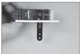
natural_image
Close-up of a hand holding a small electronic device with a black clip attached (no visible text or symbols)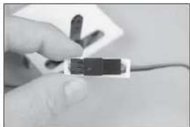
natural_image
Close-up of a hand holding a small electronic component (no visible text or symbols)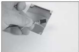
natural_image
Close-up of a hand holding a small wire on a flat surface (no text or symbols visible)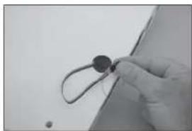
natural_image
Close-up of a gloved hand holding a small circular object with wires, against a plain background (no text or symbols visible)- Secure the aileron cover in the wing using four M3 x 15 self-tapping screws.
- Thread an M3 nut on one end of the 100mm pushrod. Slide a clevis retainer (silicone tubing) on a metal clevis, then thread the clevis on the rod. Thread a nylon ball end 12-turns on the opposite end of the threaded rod, then snap the aluminum ball into the ball end using pliers.
- Attach the ball end to the outer hole of the servo arm using the hardware included with the servo arm. Make sure to install the M3 washer (included with the kit) between the head of the screw and ball end. Tighten the hardware using a 1/4-Inch nut driver and 3/32-Inch hex wrench.
- Connect the clevis to the outer hole of the control horn. With the radio on and aileron servo centered, adjust the link to center the aileron. Once set, slide the clevis retainer (silicone tubing) over the forks of the clevis, then tighten the nut against the clevis. Use thread lock on the nut to prevent it from vibrating loose.
- Install the fl ap servo and assemble the linkage for the fl ap using the same technique as the alleron linkage. The pushrod for the fl ap linkage also measures 100mm in length. With the fl ap servo centered, adjust the link so the fl ap is in the mid-fl ap position of 12 -inches (40mm).
15.
natural_image
Simple line drawing of a mechanical component with four circular holes and a central square outline (no text or symbols)16.
natural_image
Simple line drawing of a tool or probe with a pointed tip and handle (no text or symbols)17.
natural_image
Close-up of a mechanical clamp or bracket with mounting holes, mounted on a plain surface (no text or symbols visible)18.

natural_image
Close-up of a white plastic or metal component with a thin wire, possibly a tool or bracket (no visible text or symbols)19.

natural_image
Close-up of a white paper sheet with small black markers, no visible text or symbols- Use the radio system to set the fl ap to the up position. Use the radio to center the fl ap into the neutral position.
- Use the radio system to set the fl ap to the down position. Use the radio to set the full deflection position.
□ WING INSTALLATION
- Slide the wing tube into the wing tube socket.
- Slide the wing panels together. There will be no gap between the panels.
- Fit the dowels on the leading edge of the wing into the holes in the fuselage.
20.
natural_image
Close-up of a white plastic sheet with metal clamps (no visible text or symbols)21.

natural_image
Close-up of a white sheet with small black connectors and a small figure, against a plain background (no text or symbols visible)1.

natural_image
Close-up of a metallic electronic component with a black tab and a metallic rod (no visible text or symbols)2.
natural_image
Close-up of a white surface with black and gray edges, no visible text or symbols3.
natural_image
Minimalist abstract image showing a white rectangular block placed on a dark surface with a horizontal line (no text or symbols)- Place the wing bolt plate on the wing, then thread the 1/4-20 x 13/4-inch nylon wing bolts into the blind nuts in the fuselage to secure the wing.
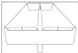
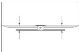
□ STABILIZER INSTALLATION
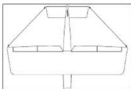
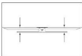
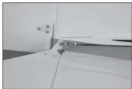
→ Check the stabilizer mounting surface on the fuselage to make sure it is flush with the fuselage sides. If the fuselage sides protrude beyond the stabilizer mounting surface, then sand them flush.
- Remove the elevators from the stabilizer. Fit the stabilizer into the notch in the fuselage. Center the stabilizer.
-
Measure from the tip of the stabilizer to the wing. Position the stabilizer so both measurements are equal.
-
Check the alignment of the stabilizer to the wing. It should be equal on both sides of the fuselage.
-
Check all alignments. Mark the outline of the fuselage on the top of the stabilizer.
4.
natural_image
Abstract geometric shapes with curved lines and triangular forms (no text or symbols)1.
natural_image
Pure geometric diagram showing a V-shaped structure with two horizontal segments and a vertical line above (no text or symbols)2.
natural_image
Simple line drawing of a symmetrical geometric shape with no text or symbols3.
natural_image
Pure mechanical diagram showing a beam supported by two supports with downward force arrows (no text or symbols)4.
natural_image
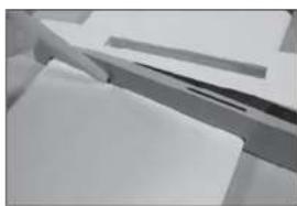
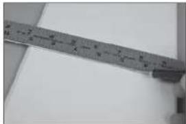
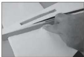
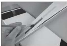
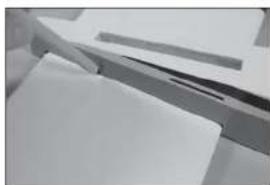
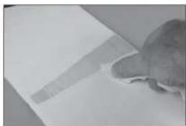
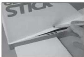
Close-up of a white surface with a metallic edge and dark markings, no visible text or symbols- Use a ruler and carefully cut the covering 1/8 inch (3 mm) inside the line drawn on the stabilizer to remove the covering from the center of the stabilizer. Remove the top and bottom covering. Use care not to cut into the underlying wood, weakening the stabilizer.
- Use a paper towel and isopropyl alcohol to remove the lines from the stabilizer.
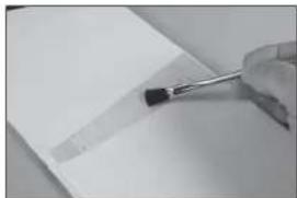
- Mix 1/2 ounce (15ml) of 30-minute epoxy. Use an epoxy brush to apply epoxy to the exposed wood on the top of the stabilizer.
- Use an epoxy brush to apply epoxy to the stabilizer mounting surface in the notch in the fuselage for the stabilizer.
- Fit the stabilizer back into position. Check the alignment following steps 1 through 3, then use a paper towel and Isopropyl alcohol to remove any excess epoxy from the fuselage and stabilizer.
5.
natural_image
Close-up of a metal ruler measuring a metric (no visible text or markings)6.
natural_image
Close-up of a small, textured object resting on a flat surface (no visible text or symbols)7.
natural_image
Close-up of a hand holding a pen tip over a blank sheet of paper (no text or symbols visible)8.
natural_image
Close-up of a hand using a power tool to apply black material to a white plastic component (no visible text or symbols)9.
natural_image
Close-up of a hand holding a pen, poised to write on paper (no visible text or symbols)- Use clamps to hold the stabilizer in position. Allow the epoxy to fully cure before proceeding.
□ FIN INSTALLATION
-
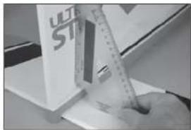
Fit the fi n into the slot in the fuselage. Use a ruler to check the alignment of the fi n to the rear edge of the fuselage.
-
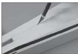
Use a felt-tipped pen to trace the outline of the fin on the top of the fuselage. Also mark the bottom of the fin along the fuselage.
-
Use a hobby knife with a #11 blade to carefully remove the covering 1/8-inch (3mm) inside the lines drawn from the top of the fuselage at the rear of the fin.
-
Use a hobby knife with a #11 blade to carefully remove the covering 1/8-inch (3mm) inside the lines drawn from the top of the fuselage at the front of the fl n.
10.
natural_image
Close-up of a mechanical assembly with metal brackets and paper sheets (no visible text or symbols)1.

natural_image
Close-up of a hand measuring a cylindrical object with a ruler, no visible text or symbols2.

3.

natural_image
Close-up of a hand using a pen to cut or mark a piece of wood or metal (no visible text or symbols)4.

natural_image
Close-up of a white surface with a black tool applying material to the top layer (no text or symbols visible)-
Use a ruler and carefully cut the covering 1/8 inch (3 mm) below the line drawn on the fi n. Remove the bottom covering. Use care not to cut into the underlying wood, weakening the fi n.
-
Mix 1/2 ounce (15ml) of 30-minute epoxy. Use an epoxy brush to apply the epoxy in the slot for the fi n and to the exposed wood on the top of the fuselage.
-
Apply epoxy to the exposed wood on the bottom of the fin where it comes in contact with the fuselage.
-
Fit the fi n in position. Check that it is square to the fuselage. Use tape if necessary to hold the fi n in position until the epoxy fully cures.
□ ELEVATOR INSTALLATION
- Attach the control horns to the top of the elevators following the same procedure as the aileron and fl ap control horns.
5.
natural_image
Close-up of a hand holding a ruler and eraser over a white rectangular object, with no visible text or symbols.6.
natural_image
Close-up of a hand holding a pen over a sheet of paper (no visible text or symbols)7.

natural_image
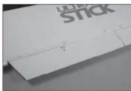
Close-up of a paintbrush applying black paint to a white plastic sheet with 'ULTRA STICK' branding (no other text or symbols visible)8.
natural_image
Close-up of a hand using a ruler to write on a white surface, with a partial view of a white box labeled 'ULT ST' visible (no readable text or symbols)1.

natural_image
Close-up of a white rectangular object with a black horizontal stripe and a small protrusion, placed on a plain gray surface (no text or symbols visible)- Drill a 1/16-inch (1.5mm) hole in the center of each hinge slot for in both the elevator and stabilizer. Prepare and install the elevator hinges, then fit the elevator to the stabilizer. Check that the ends of the elevator aligns with the ends of the stabilizer.
- Check to make sure the control horn is on the top of the elevator, and that the trim scheme from the elevator and stabilizer are on the same side.
- Repeat the previous steps to install the remaining elevator. Glue the hinges at this time following the same procedure as the aileron and fl ap hinges. Once the CA cures, gently pull on the fixed surface and control surface to make sure the hinges are glued securely. If not, apply additional CA to secure each of the hinges.
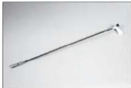
☐ RUDDER AND TAIL WHEEL INSTALLATION
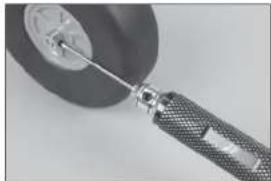
- Use a 1.5mm hex wrench to loosen the setscrews in the wheel collar for the tail wheel. Slide the wheel collar as close to the tail wheel as possible.
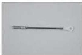
- Lightly sand the tail wheel wire where it contacts the rudder. Use a paper towel and isopropyl alcohol to remove any oil or debris from the wire.
natural_image
Close-up of a ceiling structure with diagonal white lines and dark gray panels (no text or symbols visible)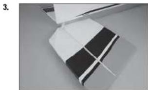
natural_image
Close-up of a folded paper or plastic sheet with black and white stripes, no visible text or symbols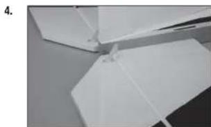
natural_image
Close-up of white paper folding fragments on a surface (no text or symbols visible)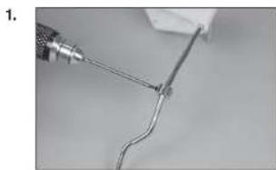
natural_image
Close-up of a wire being held by a tool, showing a curved wire or wire with a metallic tip (no text or symbols visible)
natural_image
Close-up of a hand holding a metal clip attached to a white sheet of paper (no text or symbols visible)- Mix a small amount of 15-minute epoxy. Use a toothpick to apply epoxy to the rudder where the tail wheel wire will come in contact with the exposed wood.
- Use a toothpick to apply epoxy to the tail wheel wire where it contacts the rudder.
- Fit the wire into the rudder. Use a paper towel and isopropyl alcohol to remove any excess epoxy from the rudder and wire.
- Use low-tack tape to hold the tail wheel wire in position until the epoxy fully cures. Once cured, remove the tape from the rudder.
- Install the control horn on the rudder. Note the control horn will be on the left side of the rudder.
natural_image
Close-up of a hand holding a white cable with a small black mark, no visible text or symbols
natural_image
Close-up of hands holding a thin wire or filament, no text or symbols visible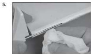
natural_image
Close-up of a white plastic sheet being folded with a cloth, no visible text or symbols
natural_image
Close-up of a white plastic component with a black rectangular clip attached, no visible text or symbols
natural_image
Close-up of a white plastic sheet with a small metallic clip attached, against a plain gray background (no text or symbols visible)-
Prepare the hinge slots and hinges for the rudder. Install the hinges and fi t the rudder to the fi n. Align the top of the fi n and rudder. Use thin CA to glue the hinges. Once the CA cures, gently pull on the fi xed surface and control surface to make sure the hinges are glued securely. If not, apply additional CA to secure each of the hinges.
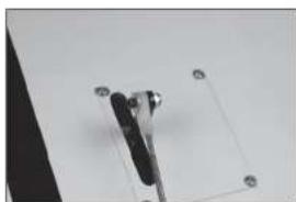
-
Position the tail wheel bracket so it is centered on the bottom of the stabilizer. Use a felt-tipped pen to mark the location for the mounting screws. Use a drill and 5/32-inch (2mm) drill bit to drill the holes for the screws.
-
Use a #1 Phillips screwdriver to thread the M3 x 20 self-tapping screws into the holes. Remove the screws, then apply thin CA into the holes to harden the threads. Once the CA has fully cured, install the three screws to secure the tail wheel bracket to the stabilizer.
-
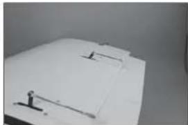
Slide the wheel collar against the tail wheel bracket and tighten the setscrew using a 1.5mm hex wrench.
-
Attach the tail wheel to the wire using a 3mm wheel collar and 3mm setscrew. Apply thread lock to the setscrew, then tighten the setscrew using a 1.5mm hex wrench.
→ Use the foam tail wheel for quieter operation when using EP power systems from asphalt runways, or the rubber tail wheel for grass runways.
8.

9.
natural_image
Close-up of hands holding a thin wire or cable with a white plastic component, no visible text or symbols10.

natural_image
Close-up of a mechanical component with angled surfaces and mounting holes (no visible text or symbols)11.
natural_image
Close-up of a white mechanical component with a curved rod and triangular base (no visible text or symbols)12.
natural_image
Close-up of a small mechanical component with a circular head and metallic shaft (no visible text or symbols)□ RADIO INSTALLATION
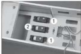
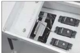
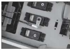
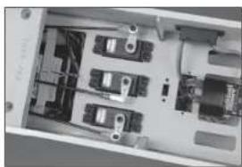
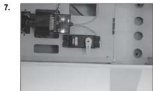
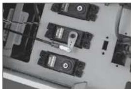
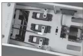
- Prepare the rudder and elevator servos by installing the rubber grommets and brass eyelets. Install the elevator (1) and the rudder (2) servos in the fuselage with the output of the servos facing the front of the fuselage.
→ Servo location may vary in the production version of your aircraft.
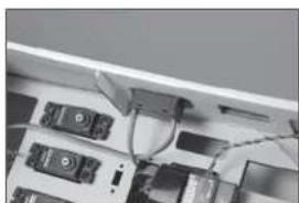
- Secure the receiver in the fuselage using two-sided tape and a hook and loop strap. Connect the rudder and elevator servos to the receiver.
→ When using the recommended receiver, make sure it is secure and installed according to the instructions provided with the receiver.
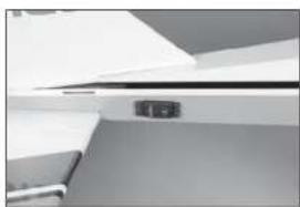
-
Use a hobby knife with a #11 blade to remove the covering from the side of the fuselage for the receiver switch. Mount the switch and connect it to the receiver.
-
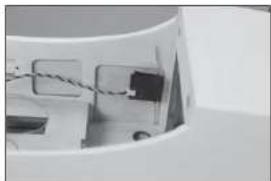
Use hook and loop tape to secure one remote receiver as far forward in the fuselage as possible.
-
The second remote receiver is mounted as far back as possible using hook and loop tape.
1.
natural_image
Interior view of a computer case with labeled buttons and wiring (no text or symbols visible)2.

natural_image
Interior view of a device with labeled ports and wiring (no readable text or symbols)3.
natural_image
Close-up of electronic devices with cables and connectors (no visible text or symbols)4.
natural_image
Close-up of a mechanical component with wires and connectors (no visible text or symbols)5.

natural_image
Interior view of an open electronic device showing internal components and wiring (no visible text or symbols)- Mount the receiver battery in the fuselage using hook and loop tape. Make a brace from mixing sticks to keep the battery secure in the fuselage.
The ignition battery can be mounted in the same location when a gas engine is being used. Connect a 6-inch (150mm) extension to the battery to connect it to the ignition switch when installed.
→ Reposition the batteries as necessary to achieve the correct Center of Gravity depending on your engine or motor selection.
-
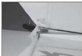
Slide the 36-inch (914mm) threaded pushrod into the pushrod tube in the fuselage. Guide the pushrod out the exit at the rear of the fuselage.
-
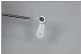
Thread an M3 nut on the pushrod. Slide a clevis retainer (silicone tubing) on a metal clevis, then thread the clevis on the pushrod. Prepare the rudder servo horn and install it on the rudder servo. Connect the clevis to the servo arm.
-
Thread an M3 nut on the pushrod. Slide a clevis retainer (silicone tubing) on a metal clevis, then thread the clevis on the pushrod. Connect the clevis to the center hole of the rudder control horn. With the radio system on and rudder servo centered, adjust the clevises to center the rudder. Once centered, slide the retainers over the forks of the clevises, then tighten the nuts against the clevises. Use thread lock on the nuts to prevent them from vibrating loose.
6.
natural_image
Interior view of a white filing cabinet with multiple black electronic components (no visible text or labels)7.

natural_image
Interior view of a refrigerator drawer showing internal compartments and storage racks (no visible text or labels)8.
natural_image
Close-up of electronic components or modules on a circuit board (no visible text or symbols)9.
natural_image
Close-up of a white mechanical component with a black cable and a small protrusion (no visible text or symbols)-
Thread a nylon ball end on the 35 V _2 -inch (900mm) elevator pushrod, then snap the ball into the ball end. Slide a 3mm washer on an M3 x 12 socket head cap screw, then thread the screw into the outer hole of the elevator servo arm.
-
Slide a 3mm washer on the screw, then a 3mm lock nut. Use a 2.5mm hex wrench and 5.5mm nut driver to tighten the hardware. Prepare both elevator pushrod at this time.
-
Slide the pushrod into the tubes, guiding out of the fuselage near the elevators. Center the elevator servos and attach the servo arms to the servos.
-
Use an M3 nut, metal clevis and clevis retainer (silicone tubing) to prepare the ends to attach the pushrods to the elevator control horns. Center the servos and adjust the clevises to center the elevators. Slide the retainer over the forks of the clevis and tighten the nut the against the clevis after applying thread lock to the nut.
→ When using heavier engines, it may be necessary to mount the elevator servos at the rear of the fuselage. Follow the steps covering this optional installation.
- Connect an 18-inch (460mm) extension to the elevator servo. Remove the covering using a hobby knife and #11 blade. Mount the elevator servo in the fuselage with the output facing toward the front of the fuselage.
10.
natural_image
Close-up of a small mechanical component with a cylindrical head and a wire, no visible text or symbols.11.

natural_image
Close-up of a small white object with a metallic rod attached to a circular base, against a plain background (no text or symbols visible)12.
natural_image
Interior view of an electronic device casing with multiple ports and connectors (no visible text or symbols)13.

natural_image
Close-up of a white door with a small handle and a small object on the side (no visible text or symbols)14.
natural_image
Close-up of a white ceiling shelf with a small black electrical outlet (no visible text or symbols)- Assemble the elevator linkages following the same procedure as the aileron and fl ap linkages using the 9^1/_4 -inch (235mm) pushrod. Attach the ball end to the elevator servo arm following the procedure outlines for the standard elevator servo installation.
- Center the elevator servo and install the servo arm. Adjust the linkage so the elevator is centered when the servo is centered. Tighten the nut against the clevis, then slide the clevis retainer (silicone tubing) over the forks of the clevis. Use threadlock on the nut to prevent it from vibrating loose.
□ LANDING GEAR INSTALLATION
- Use a fl at fl le to make a 1/4-inch (6mm) wide fl at area on the axle at the end and against the nut on the axle.
- Attach the axle to the landing gear using the nut supplied with the axle. With the fl at areas of the axle facing down, tighten the axle using two 1/2-inch wrenches.
-
Slide a 5/32-inch wheel collar on the axle. Do not tighten the setscrew at this time.
-
natural_image
Metal tool with a pointed tip and handle, isolated on plain background (no text or symbols)
natural_image
Close-up of a white electronic device with a metallic clip and a small sensor, no visible text or symbols.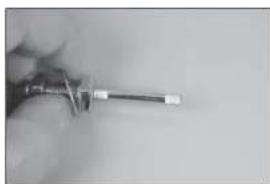
natural_image
Close-up of a hand holding a screwdriver (no visible text or symbols)
natural_image
Close-up of a white mechanical clamp or bracket with a metallic rod inserted (no visible text or symbols)
natural_image
Close-up of a white mechanical clamp or bracket with a metal rod inserted (no visible text or symbols)- Place a drop of light machine oil on the axle, then slide the wheel on the axle. Position the wheel collar fl ush with the end of the axle. Secure the wheel using a 5/32-inch wheel collar, tightening the setscrew on the outer fl at area. Make sure to use thread lock on the setscrew to prevent it from vibrating loose.
- Slide the inner wheel collar against the wheel then tighten the setscrew. Check that the wheel can spin freely and reposition the collar as necessary.
→ Check that the M4 x 15 socket head cap screw thread easily into the blind nuts. If not, use a 4mm tap to clear the threads of the blind nuts so the screw threads in easily.
- Position the gear on the bottom of the fuselage. The gear angle forward as shown in the photo.
-
Attach the gear to the fuselage using four M4 x 15 socket head cap screws and four M4 washers. Use thread lock on the screws.
-
natural_image
Close-up of a mechanical tool interacting with a circular component (no visible text or symbols)
natural_image
Close-up of a white aircraft landing gear with attached metal bracket (no visible text or symbols)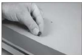
natural_image
Close-up of a hand holding a small object on a flat surface (no visible text or symbols)
natural_image
Close-up of a circular mechanical component mounted on a stand (no visible text or symbols)
natural_image
Close-up of a white mechanical component with four black holes, possibly part of a fan or wing (no text or symbols visible)- Attach the wheel pants to the landing gear using two M3 x 10 button head screws and two M3 washers. Apply thread lock on the screws, then tighten them using a 2mm hex wrench.
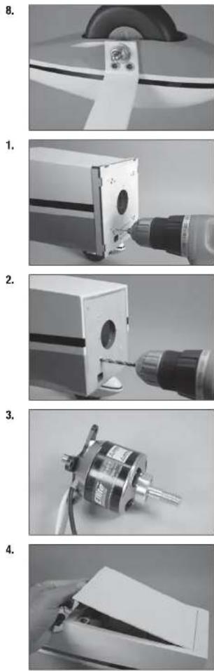
□ ELECTRIC MOTOR INSTALLATION
-
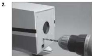
Place the mounting template on the fuselage. Use a 5/32-inch (2mm) drill bit to drill the mounting holes necessary to mount your particular motor choice.
-
Use a drill and 3/16-inch (5mm) drill bit to enlarge the holes to mount the electric motor.
-
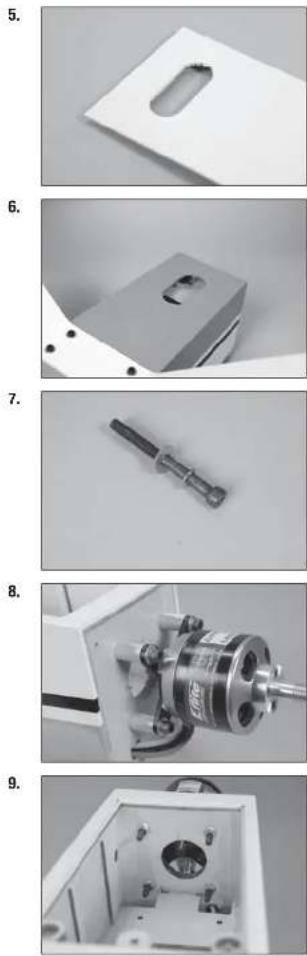
Use a #2 Phillips screwdriver to attach the X-mount to the rear of the motor. Use a 2.5mm hex wrench to attach the propeller adapter to the front of the motor. Use thread lock on all metal-to-metal fasteners to prevent them from vibrating loose.
-
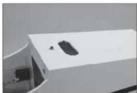
Remove the hatch from the fuselage by lifting it at the rear, then sliding it out of the fuselage.
- Trim the covering inside the opening at the rear of the hatch. Use a covering iron to seal the covering into the opening. The opening is used to remove the hatch to access the motor batteries.
- There is also an opening in the bottom of the fuselage that can be opened to increase the airflow to the speed control and batteries.
- Slide an M5 lock washer, then an M5 washer on the M5 x 40 socket head cap bolt. Prepare four bolts at this time.
- Slide the bolts though the motor mount, then through the four 20mm aluminum spacers. The bolts are then inserted into the holes drilled in the firewall.
- Use four M5 flanged nuts inside the fuselage to secure the motor to the fl rewall.
-
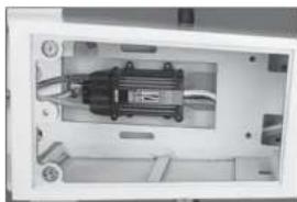
Secure the speed controller inside the fuselage. Make any connections to the motor, and for the battery, before proceeding.
-
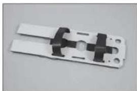
Place hook and loop tape on the battery tray and battery to prevent it from sliding on the tray during flight. Hook and loop straps can be installed to secure the battery to the tray.
-
Install the battery tray in the fuselage. Secure it at the front using two M3 x 16 socket head cap screws and two M3 washers. Use thread lock on the screws to prevent them from vibrating loose.
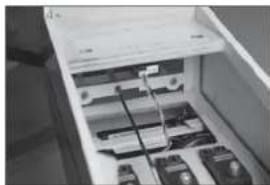
-
Use the hook and loop straps to secure the batteries in the fuselage. Make sure not to cover any warning labels on the battery.
→ Reposition the batteries as necessary to achieve the correct Center of Gravity depending on your motor selection.
- A battery eliminator (BEC) can be installed instead of using a separate battery for the receiver. Connect the BEC using the instructions provided with your particular device.
10.
natural_image
Interior view of a mechanical device with visible wiring and components (no text or symbols)11.

natural_image
Close-up of a white plastic electrical connector with black connectors and mounting holes (no text or symbols visible)12.

natural_image
Close-up of a mechanical device with internal components and mounting holes (no visible text or symbols)13.

natural_image
Exterior view of a white electronic device casing with internal components (no visible text or symbols)14.

natural_image
Interior view of an electronic device with visible wiring and components (no text or symbols)-
Place the hatch back into position on the fuselage. The magnets will hold the hatch securely under normal fl ying conditions. In extreme fl ight, it is recommended to secure the hatch using an M3 x 10 mm socket head cap screw and M3 washer. Use a drop of canopy glue on the threads to keep the screw from vibrating loose.
-
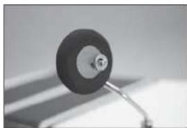
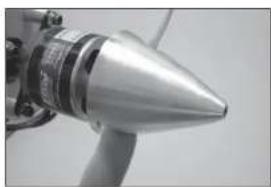
Fit the spinner backplate to the motor. It may be necessary to enlarge the hole in the backplate to fit the propeller adapter.
-
Secure the propeller using the washer and nut included with the motor. Use a box wrench to tighten the nut.
-
Attach the spinner cone using the hardware included with the spinner.
□ GAS ENGINE INSTALLATION
- Place the mounting template on the fuselage. Use a 5/32-inch (2mm) drill bit to drill the holes necessary to mount your particular motor choice.
15.
natural_image
Exterior view of a white electronic device with a small black component on top (no visible text or symbols)16.

natural_image
Close-up of a mechanical component with a metallic cylindrical assembly and a central shaft (no visible text or symbols)17.

natural_image
Close-up of a metallic mechanical component with no visible text or symbols18.
natural_image
Close-up of a metallic conical object with a protruding rod (no visible text or symbols)1.

natural_image
Close-up of a mechanical component with a cylindrical tool inserted, no visible text or symbols- Use a drill and 3/16-inch (5mm) drill bit to enlarge the holes to mount the engine. Enlarge the hole for the throttle pushrod using a drill and 9/64-inch (3.5mm) drill bit.
- Remove the hatch from the fuselage by lifting it at the rear, then sliding it out of the fuselage.
- Slide an M5 lock washer, then an M5 washer on the M5 x 40 socket head cap bolt. Prepare four bolts at this time.
- Slide the bolts though the motor mount. The bolts are then inserted into the holes drilled in the fi rewall.
- Use four M5 fl angled nuts inside the fuselage to secure the motor to the fl rewall.
natural_image
Close-up of a mechanical tool with a drill bit inserted into a box (no visible text or symbols)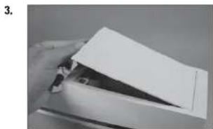
natural_image
Close-up of a hand holding a white sheet of paper over a metal clip (no visible text or symbols)
natural_image
Metal mechanical component with cylindrical end and threaded shaft (no visible text or symbols)
natural_image
Close-up of a mechanical device with a coiled spring and control panel (no visible text or symbols)
natural_image
Close-up of a mechanical component with internal parts and a metallic bracket (no visible text or symbols)- Center the throttle stick and trim. Place the servo arm on the throttle servo perpendicular to the servo centerline. Remove any arms that will not be used from the servo arm.
- Remove the servo arm from the throttle servo. Thread the screw into the hole on the servo arm as indicated in the engine instruction manual.
- Place a drop of thread lock on the screw, then install the M2 nut to secure the connector. The servo arm can then be reinstalled on the servo.
- Insert the 15 12 -inch (394mm) pushrod tube into the hole in the fi rewall.
- Position the pushrod tube so 3/4-inch (19mm) of the tube protrudes from the fl rewall.
natural_image
Interior view of a laboratory or lab equipment unit with control panels and tubing (no visible text or symbols)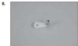
natural_image
White cylindrical object with a small metallic tip, placed on a plain gray surface (no text or symbols visible)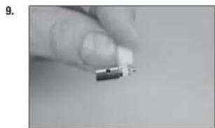
natural_image
Close-up of a hand holding a small electronic component (no visible text or symbols)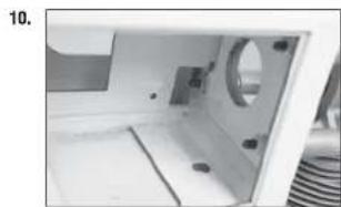
natural_image
Interior view of a machine cabin with visible door, wheels, and insulation (no text or symbols)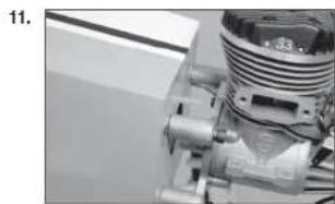
natural_image
Close-up of a mechanical component with threaded shaft and housing (no visible text or symbols)-
Use side cutters to trim the pushrod tube at the front edge of the servo tray.
-
Slide a clevis retainer (silicone tubing) over the nylon clevis. Thread the clevis on the 23 ^1/2 -inch (570mm) pushrod wire. Slide the wire into the pushrod tube, then connect the clevis to the carburetor throttle arm. Slide the clevis retainer (silicone tubing) over the forks of the clevis to secure its position.
-
Slide the pushrod wire through the connector on the servo. Close the carburetor, and move the throttle stick to low throttle. Tighten the setscrew to secure the pushrod wire in the connector.
-
Use medium CA to glue the pushrod spacer to the pushrod tube and fuselage side to support the pushrod.
-
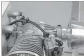
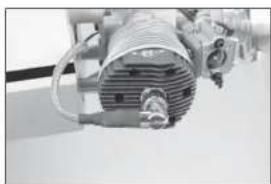
Attach the muffler to the engine using the screws included with the muffler.
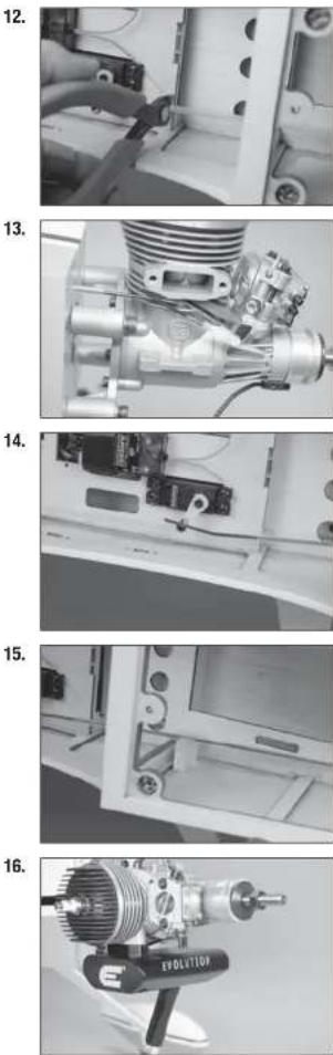
- Fit the spinner backplate to the motor. It may be necessary to enlarge the hole in the backplate or use the included adapters to fit the propeller shaft.
- Attach the propeller using the adapters and washer from the spinner. Tighten the first nut, then hold it securely while tightening the second nut.
- Attach the spinner cone using the hardware included with the spinner.
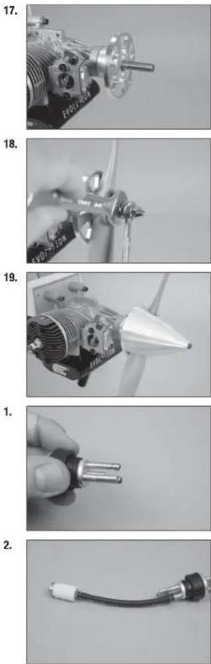
FUEL TANK INSTALLATION
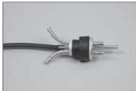
- Prepare the stopper assembly by placing a small amount of solder on the end of the tubes shown. This will help keep the fuel lines secure when installed. Use care not to overheat the tubing, which could melt the stopper material.
- Secure the tubing to the clunk and tube from the stopper using thin wire. This will keep the tubing from sliding loose inside the tank. Use the clunk and tubing included with the engine.
- Bend the vent and fill lines as shown.
→ A clunk can also be attached to the fill line, which will allow better removal of the fuel after a flying session.
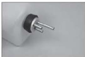
-
Insert the stopper fully into the tank. Check that the clunk can move freely in the tank. The brass tube to the clunk can be moved in our out to fine-tune the position of the clunk inside the tank. Once set, tighten the screw using a #1 Phillips screwdriver to secure the clunk in the tank.
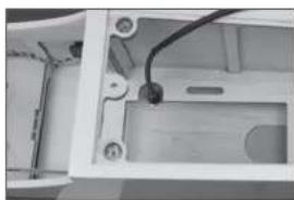
-
Attach a 6-inch (152mm) piece of fuel tubing to the overfl ow fi tting (included with the fuel fi ller). Remove the covering from the fuselage, then secure the overfl ow fi tting in the fuselage.
-
Secure a 5-inch (127mm) fuel line to the fi II line of the tank. The overfl ow line can be attached to the vent, as well as the remaining tubing to the clunk line that will eventually attach to the carburetor. Tie wraps can also be used to secure the fuel lines as well as wire ties.
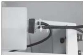
-
Mount the fuel tank in the fuselage. The fi II fi tting has been installed in the side of the fuselage, and the fi II line can be routed through the fi tting. Route the line from the clunk through the opening in the fi rewall.
3.
natural_image
Close-up of a black electrical plug with three leads, isolated on white background (no text or symbols)4.
natural_image
Close-up of a black and silver electrical plug with three pins (no text or symbols visible)5.
natural_image
Interior view of a device housing with visible wiring and components (no text or symbols)6.
natural_image
Close-up of a white electronic device with black connectors and wiring (no visible text or symbols)7.
natural_image
Interior view of a mechanical device showing internal components and wiring (no visible text or symbols)- Install the fuel fi iter in the line to the carburetor. The fuel line can then be secured to the carburetor.
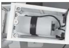
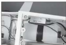
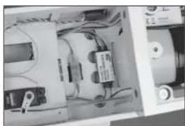
□ IGNITION INSTALLATION
-
Mount the ignition module in the fuselage. Route the spark plug cap through the hole in the fi rewall. Connect the lead from the engine to the appropriate lead on the module.
-
Attach the spark plug cap to the spark plug. Secure the lead if necessary so it does not interfere with the operation of the engine.
-
We have installed the optional optical kill switch in our model using hook and loop tape. A standard switch can also be mounted on the side of the fuselage. Connect the switch to the battery.
→ An RPM sensor has also been installed in the fuselage using hook and loop tape.
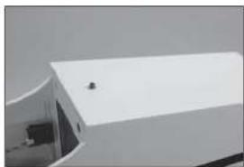
- Place the hatch back into position on the fuselage. The magnets will hold the hatch securely under normal fl ying conditions. In extreme fl ight, It is recommended to secure the hatch using an M3 x 10 mm socket head cap screw and M3 washer. Use a drop of canopy glue on the threads to keep the screw from vibrating loose.
8.
natural_image
Close-up of industrial machinery components with hoses and tubing (no visible text or symbols)1.
natural_image
Close-up of a mechanical or electronic component with wires and a black rectangular block (no visible text or symbols)2.
natural_image
Industrial machine with coiled components and wiring (no visible text or symbols)3.
natural_image
Interior view of an electronic device showing internal components and wiring (no visible text or symbols)4.
natural_image
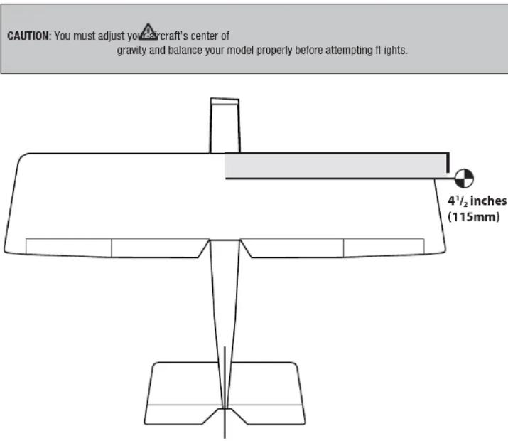
Exterior view of a modern white building with a curved roof and small window (no signage or text visible)□ CENTER OF GRAVITY
An important part of preparing the aircraft for flight is properly balancing the model.
- Attach the wing panels to the fuselage. Make sure to connect the leads from the aileron to the appropriate leads from the receiver. Make sure the leads are not exposed outside the fuselage before tightening the wing bolts. Your model should be flight-ready before balancing.
- The recommended Center of Gravity (CG) location for your model is 4 V_2 inches (115mm) behind the leading edge of the wing.
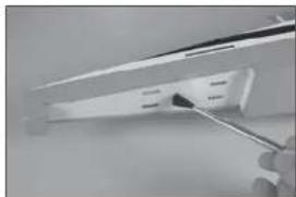
- When balancing your model, make sure it is assembled and ready for flight. Support the plane upright at the marks made on the wing with your fingers or a commercially available balancing stand.
CONTROL THROWS
- Tum on the transmitter and receiver of your model. Check the movement of the rudder using the transmitter. When the stick is moved to the right, the rudder should also move right. Reverse the direction of the servo at the transmitter if necessary.
- Check the movement of the elevator with the radio system. Moving the elevator stick toward the bottom of the transmitter will make the airplane elevator move up.
- Check the movement of the ailerons with the radio system. Moving the aileron stick to the right will make the right aileron move up and the left aileron move down.
- Use a throw meter to adjust the throw of the elevator, allerons and rudder. Set the high rates first, then use the rate functions to set the remaining rates.
Aileron (high rate): Aileron (low rate):
| Up: | 2^1/_16 inches (68mm) Up: 1 | ^3/_16 inches (30mm) |
| Down: | 2^5/_32 inches (55mm) Down: 1 inch (25mm) |
Elevator (high rate): Elevator (low rate):
| Up: | 2^5/_32 inches (55mm) Up: 1 | 1/_16 inches (27mm) |
| Down: | 2^5/_32 inches (55mm) Down: 1 | 1/_16 inches (27mm) |
Rudder (high rate):
| Right: | 2^3/_4 inches (70mm) | Right: | 1^3/_8 inches (35mm) |
| Left: | 2^3/_4 inches (70mm) | Left: | 1^3/_8 inches (35mm) |
Flaps:
| Mid | 1 inches (25mm) |
| Landing | 2^s/_32 inches (55mm) |
These are general guidelines measured from our own flight tests. You can experiment with different rates to match your preferred style of flying.
Travel Adjust and Sub-Trims are not listed and should be adjusted according to each individual model and preference. Always install the control horns 90 degrees to the servo center line. Use sub-trim as a last resort to center the servos.
We highly recommend re-binding the radio system once all of the control throws are set. This will keep the servos from moving to their endpoints until the transmitter and receiver connect.
□ PREFLIGHT CHECKLIST
- Charge the transmitter, receiver and motor battery for your airplane. Use the recommended charger supplied with your radio system. Follow the instructions provided with the radio. Charge the radio system the night before each flying session. Charge the transmitter and receiver batteries using only included or manufacturer-recommended chargers. Follow all manufacturer's instructions for your electronic components.
- Check the radio installation and make sure all control surfaces (aileron, elevator, rudder and throttle) move correctly (i.e., the correct direction and with the recommended throws).
- Check all the hardware (control horns, servo horns, and clevises) to make sure they are secure and in good condition.
- Prior to each 11 ying session (and especially with a new model), perform a range check of your radio system. See your radio manual for the recommended range and instructions for your particular radio system.
- Run the motor. With the model securely anchored, repeat the range check procedure. The range should not be signifi cantly affected. If it is, do not attempt to fly! Remove the radio equipment and have it inspected by the manufacturer.
DAILY FLIGHT CHECKS
- Check the battery voltage of the transmitter battery. Do not fly below the manufacturer's recommended voltage. To do so can crash your aircraft.
When you check these batteries, ensure you have the polarities correct on your expanded scale voltmeter.
- Check all hardware (linkages, screws, nuts, and bolts) prior to each day's fl light. Ensure that binding does not occur and that all parts are properly secured.
- Ensure all surfaces are moving in the proper manner.
- Perform a ground range check before each day's fl ying session.
- Prior to starting your aircraft, turn off your transmitter, then turn it back on. Do this each time you start your aircraft. If any critical switches are on without your knowledge, the transmitter alarm will sound a warning.
- Check that all trim levers are in the proper location.
- All servo pigtails and switch harness plugs should be secured in the receiver. Make sure the switch harness moves freely in both directions.
□ LIMITED WARRANTY
What this Warranty Covers
Horizon Hobby, LLC, (Horizon) warrants to the original purchaser that the product purchased (the "Product") will be free from defects in materials and workmanship at the date of purchase.
What Is Not Covered
This warranty is not transferable and does not cover (i) cosmetic damage, (ii) damage due to acts of God, accident, misuse, abuse, negligence, commercial use, or due to improper use, installation, operation or maintenance, (iii) modification of or to any part of the Product, (iv) attempted service by anyone other than a Horizon Hobby authorized service center, (v) Product not purchased from an authorized Horizon dealer, (vi) Product not compliant with applicable technical regulations, or (vii) use that violates any applicable laws, rules, or regulations.
OTHER THAN THE EXPRESS WARRANTY ABOVE, HORIZON MAKES NO OTHER WARRANTY OR REPRESENTATION, AND HEREBY DISCLAIMS ANY AND ALL IMPLIED WARRANTIES, INCLUDING, WITHOUT LIMITATION, THE IMPLIED WARRANTIES OF NON-INFRINGEMENT, MERCHANTABILITY AND FITNESS FOR A PARTICULAR PURPOSE. THE PURCHASER ACKNOWLEDGES THAT THEY ALONE HAVE DETERMINED THAT THE PRODUCT WILL SUITABLY MEET THE REQUIREMENTS OF THE PURCHASER'S INTENDED USE.
Purchaser's Remedy
Horizon's sole obligation and purchaser's sole and exclusive remedy shall be that Horizon will, at its option, either (i) service, or (ii) replace, any Product determined by Horizon to be defective. Horizon reserves the right to inspect any and all Product(s) involved in a warranty claim. Service or replacement decisions are at the sole discretion of Horizon. Proof of purchase is required for all warranty claims. SERVICE OR REPLACEMENT AS PROVIDED UNDER THIS WARRANTY IS THE PURCHASER'S SOLE AND EXCLUSIVE REMEDY.
Limitation of Liability
HORIZON SHALL NOT BE LIABLE FOR SPECIAL, INDIRECT, INCIDENTAL OR CONSEQUENTIAL DAMAGES, LOSS OF PROFITS OR PRODUCTION OR COMMERCIAL LOSS IN ANY WAY, REGARDLESS OF WHETHER SUCH CLAIM IS BASED IN CONTRACT, WARRANTY, TORT, NEGLIGENCE, STRICT LIABILITY OR ANY OTHER THEORY OF LIABILITY, EVEN IF HORIZON HAS BEEN ADVISED OF THE POSSIBILITY OF SUCH DAMAGES. Further, In no event shall the liability of Horizon exceed the individual price of the Product on which liability is asserted. As Horizon has no control over use, setup, finl assembly, modification or misuse, no liability shall be assumed nor accepted for any resulting damage or injury. By the act of use, setup or assembly, the user accepts all resulting liability. If you as the purchaser or user are not prepared to accept the liability associated with the use of the Product, purchaser is advised to return the Product immediately in new and unused condition to the place of purchase.
Law
These terms are governed by Illinois law (without regard to conflict of law principals). This warranty gives you specific legal rights, and you may also have other rights which vary from state to state. Horizon reserves the right to change or modify this warranty at any time without notice.
WARRANTY SERVICES
Questions, Assistance, and Services
Your local hobby store and/or place of purchase cannot provide warranty support or service. Once assembly, setup or use of the Product has been started, you must contact your local distributor or Horizon directly. This will enable Horizon to better answer your questions and service you in the event that you may need any assistance. For questions or assistance, please visit our website at www.horizonhobby.com, submit a Product Support Inquiry, or call the toll free telephone number referenced in the Warranty and Service Contact Information section to speak with a Product Support representative.
Inspection or Services
If this Product needs to be inspected or serviced and is compliant in the country you live and use the Product in, please use the Horizon Online Service Request submission process found on our website or call Horizon to obtain a Return Merchandise Authorization (RMA) number. Pack the Product securely using a shipping carton. Please note that original boxes may be included, but are not designed to withstand the rigors of shipping without additional protection. Ship via a carrier that provides tracking and insurance for lost or damaged parcels, as Horizon is not responsible for merchandise until it arrives and is accepted at our facility. An Online Service Request is available at http://www.horizonhobby.com/content/_service-centerRender-service-center. If you do not have internet access, please contact Horizon Product Support to obtain a RMA number along with instructions for submitting your product for service. When calling Horizon, you will be asked to provide your complete name, street address, email address and phone number where you can be reached during business hours. When sending product into Horizon, please include your RMA number, a list of the Included items, and a brief summary of the problem. A copy of your original sales receipt must be included for warranty consideration. Be sure your name, address, and RMA number are clearly written on the outside of the shipping carton.
NOTICE: Do not ship LiPo batteries to Horizon. If you have any issue with a LiPo battery, please contact the appropriate Horizon Product Support offi ce.
Warranty Requirements
For Warranty consideration, you must include your original sales receipt verifying the proof-of-purchase date. Provided warranty conditions have been met, your Product will be serviced or replaced free of charge. Service or replacement decisions are at the sole discretion of Horizon.
Non-Warranty Service
Should your service not be covered by warranty, service will be completed and payment will be required without notification or estimate of the expense unless the expense exceeds 50% of the retail purchase cost. By submitting the item for service you are agreeing to payment of the service without notification. Service estimates are available upon request. You must include this request with your item submitted for service. Non-warranty service estimates will be billed a minimum of 12 hour of labor. In addition you will be billed for return freight. Horizon accepts money orders and cashier's checks, as well as Visa, MasterCard, American Express, and Discover cards. By submitting any item to Horizon for service, you are agreeing to Horizon's Terms and Conditions found on our website http://www.horizonhobby.com/content/_service-center_render-service-center.
ATTENTION: Horizon service is limited to Product compliant in the country of use and ownership. If received, a non-compliant Product will not be serviced. Further, the sender will be responsible for arranging return shipment of the un-serviced Product, through a carrier of the sender's choice and at the sender's expense. Horizon will hold non-compliant Product for a period of 60 days from notification, after which it will be discarded.
10/15
☐ WARRANTY AND SERVICE CONTACT INFORMATION
| Country of Purchase | Horizon Hobby Contact Information Address | ||
| United States of America | Horizon Service Center (Repairs and Repair Requests) | servicecenter.horizonhobby.com/RequestForm/ | 4105 Fieldstone RdChampaign, Illinois, 61822 USA |
| Horizon Product Support (Product Technical Assistance) | productsupport@horizonhobby.com877-504-0233 | ||
| Sales | websales@horizonhobby.com800-338-4639 | ||
| United Kingdom | Service/Parts/Sales: Horizon Hobby Limited | sales@horizonhobby.co.uk Units+44 (0) 1279 641 097 | 1–4 , Ployters Rd, Staple TyoHarlow, Essex, CM18 7NS, United Kingdom |
| Germany | Horizon Technischer Service service@horizonhobby.de Christian-Junge-Straße 1 | ||
| Sales: Horizon Hobby GmbH +49 (0) 4121 2655 100 | 25337 Elmshorn, Germany | ||
| France | Service/Parts/Sales: Horizon Hobby SAS | infofrance@horizonhobby.com+33 (0) 1 60 18 34 90 | 11 Rue Georges Charpak 77127 Lieusaint, France |

☐ INSTRUCTIONS FOR DISPOSAL OF WEEE BY USERS IN THE EUROPEAN UNION
This product must not be disposed of with other waste. Instead, it is the user's responsibility to dispose of their waste equipment by handing it over to a designated collections point for the recycling of waste electrical and electronic equipment. The separate collection and recycling of your waste equipment at the time of disposal will help to conserve natural resources and ensure that it is recycled in a manner that protects human health and the environment. For more information about where you can drop off your waste equipment for recycling, please contact your local city offi ce, your household waste disposal service or where you purchased the product.
□ FAA INFORMATION
Prior to flying, contact your local or regional modeling organizations for guidance and familiarize yourself with the current local rules and FAA regulations governing model aviation in your location. More information about model aviation can be found at www.modelaircraft.org. The Federal Aviation Administration can be found online at www.faa.gov.
You are required to register with the FAA if you own this product. For up-to-date information on how to register with the FAA, please visit https://registermyuas.faa.gov/ For additional assistance on regulations and guidance on UAS usage, visit knowbeforeyoufl y.org/
□ MONTAGE VON QUERRUDER UND KLAPPE
natural_image
Close-up of a hand holding a tool next to a white rectangular object (no visible text or symbols)2.
natural_image
Close-up of a white rectangular object with a small mark on the surface (no visible text or symbols)3.
natural_image
Two irregular white geometric shapes on a plain gray background (no text or symbols)4.

natural_image
Exterior view of a modern office building (no signage)5.

natural_image
Close-up of a small metallic object on a plain surface (no visible text or symbols)natural_image
Close-up of a gloved hand holding a pliers near a small object on a white surface (no text or symbols visible)7.
natural_image
Close-up of a hand holding a metal cutting tool with small holes (no text or symbols visible)8.
natural_image
Close-up of a metallic tool interacting with a white panel or sheet metal (no visible text or symbols)9.

natural_image
Close-up of a hand holding a small white plastic clip (no text or symbols visible)10

natural_image
Close-up of a white aircraft wing with a visible propeller and arrow (no text or symbols)natural_image
White rectangular object with black top and small protrusions, possibly a battery or sensor component (no visible text or symbols)12.

natural_image
Close-up of a white rectangular object with a small mark and faint lines, placed on a dark surface (no visible text or symbols)13.

natural_image
Close-up of a hand holding a pen, partially visible against a plain background (no text or symbols)14.

natural_image
Close-up of a hand holding a black rectangular object with white diagonal lines, possibly part of a device or component (no visible text or symbols)15.
natural_image
Close-up of a white plastic sheet with a black 'STICK' logo on top, showing a small crack (no readable text or symbols beyond the logo)natural_image
Close-up of a hand holding a pen over a white sheet of paper (no visible text or symbols)1.
natural_image
Close-up of a hand holding a small object with a pen, poised to write on paper (no visible text or symbols)2.
natural_image
Close-up of a white plastic component with a recessed slot and mounting holes (no visible text or symbols)3.

natural_image
Close-up of a hand holding a white electronic device with a cable (no visible text or symbols)4.
natural_image
Close-up of a precision tool tip cutting through a white surface (no text or symbols visible)natural_image
Close-up of a metallic object with a suspended rod and triangular base, no visible text or symbols
natural_image
Close-up of a mechanical component with a glass pouring liquid into a rectangular slot (no visible text or symbols)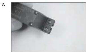
natural_image
Close-up of a hand holding a small metal wire tool (no visible text or symbols)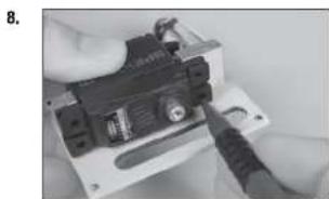
natural_image
Close-up of hands installing or adjusting a small electronic component (no visible text or symbols)
natural_image
Close-up of a mechanical component with a pointed tool inserted, no visible text or symbolsnatural_image
Close-up of a black electronic device with control panel and indicator lights, no visible text or symbols
natural_image
Close-up of a hand holding a small electronic device with a black clip attached (no visible text or symbols)
natural_image
Close-up of a hand holding a small black electronic component with wires, no visible text or symbols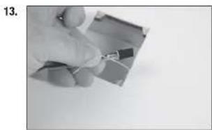
natural_image
Close-up of a hand holding a small electronic component (no visible text or symbols)
natural_image
Close-up of a gloved hand holding a small circular object with a string, against a plain background (no text or symbols visible)natural_image
Simple line drawing of a mechanical part with four circular holes and a central rod (no text or symbols)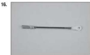
natural_image
Close-up of a metallic tool with a handle and circular end, no visible text or symbols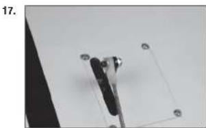
natural_image
Close-up of a mechanical clamp or bracket with mounting holes, no visible text or symbols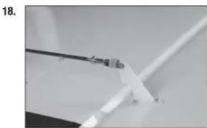
natural_image
Close-up of a white plastic or glass tube being held by tweezers against a plain background (no text or symbols visible)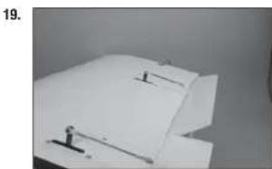
natural_image
Close-up of white paper sheets with small black markers, no visible text or symbolsnatural_image
Close-up of a white plastic sheet with metal clamps and a small protrusion, no visible text or symbols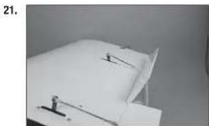
natural_image
Close-up of a white sheet with a small ruler and a paper clip, no visible text or symbols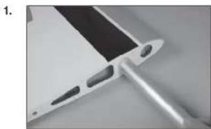
natural_image
Close-up of a metallic electronic component with a black tab and two protruding pins (no visible text or symbols)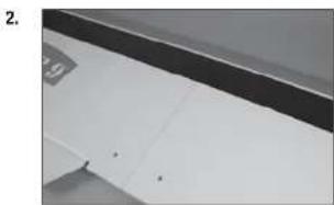
natural_image
Close-up of a white cabinet or shelf with black and gray panels, no visible text or symbols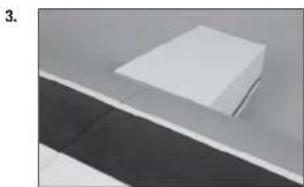
natural_image
Exterior view of a modern office building (no signage)natural_image
Abstract geometric shapes with diagonal lines and triangular forms (no text or symbols)1.
natural_image
Pure geometric diagram of a V-shaped structure with horizontal and vertical dimension lines (no text or symbols)2.
natural_image
Simple line drawing of a symmetrical geometric shape with no text or symbols3.
natural_image
Pure mechanical diagram showing a beam supported by two supports with downward force arrows (no text or symbols)4.
natural_image
Close-up of a white paper sheet with a dark horizontal line above it, no visible text or symbols6.
natural_image
Close-up of a hand holding a small object against a plain background (no visible text or symbols)7.

natural_image
Close-up of a hand holding a small tool near a blank sheet of paper (no visible text or symbols)8.

natural_image
Close-up of a hand using a screwdriver to apply black plastic components on a wall (no text or symbols visible)9.
natural_image
Close-up of a hand holding a pen over a blank sheet of paper (no visible text or symbols)natural_image
Pure mechanical assembly diagram without any text, numbers, or symbols1.
natural_image
Close-up of a hand measuring a cylindrical object with a ruler, no visible text or symbols2.
3.

natural_image
Close-up of a hand using a tool to cut or mark a wooden plank (no visible text or symbols)4.
natural_image
Close-up of a white surface with a black pen inserted, no visible text or symbolsnatural_image
Close-up of a hand using a ruler to cut a white rectangular object on a surface (no visible text or symbols)6.

natural_image
Close-up of a hand holding a pen over a sheet of paper (no visible text or symbols)7.

natural_image
Close-up of a hand holding a paintbrush applying paint to a white plastic sheet with 'ULTRA STICK' branding (no other text or symbols visible)8.

natural_image
Close-up of a hand using a ruler to measure a piece of paper or metal, with no visible text or symbols.1.
natural_image
Close-up of a white electronic device with a black tab and small metallic tip, placed on a plain gray surface (no text or symbols visible)natural_image
Close-up of a ceiling structure with diagonal white lines and dark gray panels (no text or symbols visible)
natural_image
Close-up of a folded paper or plastic sheet with black and white stripes, no visible text or symbols
natural_image
Close-up of white paper folding panels on a surface (no text or symbols visible)
natural_image
Close-up of a wire being held by a tool, showing a curved wire and a small object (no text or symbols visible)
natural_image
Close-up of a hand holding a metal clip attached to a white sheet of paper (no text or symbols visible)natural_image
Close-up of a hand holding a white cable with a small black mark, no visible text or symbols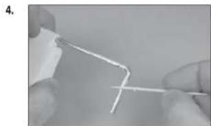
natural_image
Close-up of hands holding a thin, white wire or filament against a plain background (no text or symbols visible)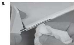
natural_image
Close-up of a white plastic sheet being cut with a metal clip, showing texture and surface details (no text or symbols visible)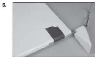
natural_image
Close-up of a white aircraft wing with a black plastic clip attached, no visible text or symbols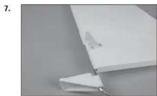
natural_image
Close-up of a white plastic sheet with a small metallic clip attached, against a plain gray background (no text or symbols visible)natural_image
Close-up of hands using a tool to cut or wire a piece of paper or plastic (no visible text or symbols)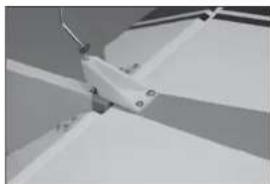
natural_image
Close-up of a mechanical component with no visible text or symbols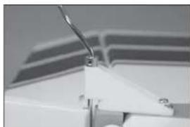
natural_image
Close-up of a white mechanical component with a curved wire, possibly part of a device or bracket (no visible text or symbols)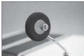
natural_image
Close-up of a black circular object with a metallic shaft, possibly a knob or dial, against a blurred background (no text or symbols visible)□ MONTAGE DES FUNKGERÄTS
natural_image
Interior view of a computer case with labeled ports (no text or symbols visible)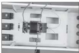
natural_image
Interior view of an electronic device with labeled ports and wiring (no readable text or symbols)
natural_image
Close-up of electronic devices with cables and connectors (no visible text or symbols)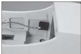
natural_image
Close-up of a mechanical component with wires and a small block, no visible text or symbols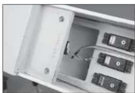
natural_image
Interior view of an electronic device showing a white enclosure with multiple ports and a cable inserted (no visible text or symbols)natural_image
Interior view of a white filing cabinet with multiple black electronic components (no visible text or labels)7.
natural_image
Interior view of a refrigerator drawer showing internal compartments and storage racks (no visible text or labels)8.
natural_image
Top-down view of an electronic device cluster with multiple ports and connectors (no visible text or symbols)9.

natural_image
Close-up of a white vehicle's side panel with a black cable and a small mark, no visible text or symbolsnatural_image
Close-up of a small mechanical component with a cylindrical head and a wire, no visible text or symbols.11.

natural_image
Close-up of a small white object with a metallic rod attached to a circular base, against a plain background (no text or symbols visible)12.
natural_image
Interior view of an electronic device casing with multiple ports and connectors (no visible text or symbols)13.
natural_image
Close-up of a white door with a small handle and a small object on the side (no visible text or symbols)14.

natural_image
Close-up of a white ceiling shelf with a small black electrical outlet (no visible text or symbols)natural_image
Close-up of a metallic medical or laboratory tool with a pointed tip and handle (no visible text or symbols)
natural_image
Close-up of a white electronic device with a metallic connector and paper sheet (no visible text or symbols)
natural_image
Close-up of a hand holding a screwdriver (no visible text or symbols)
natural_image
Close-up of a white mechanical clamp or bracket with a metal rod inserted (no visible text or symbols)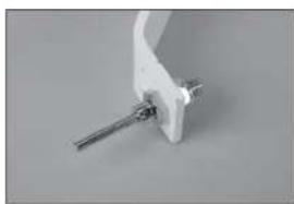
natural_image
Close-up of a white mechanical clamp or bracket with metal pins (no visible text or symbols)natural_image
Close-up of a mechanical tool with a metallic handle and circular dial (no visible text or symbols)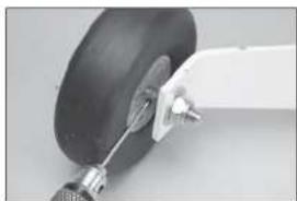
natural_image
Close-up of a mechanical component with a curved arm and a black circular base (no visible text or symbols)
natural_image
Close-up of a hand holding a small object on a flat surface (no visible text or symbols)
natural_image
Close-up of a circular mechanical component mounted on a stand (no visible text or symbols)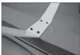
natural_image
Close-up of a white mechanical component with four black holes, possibly part of a fan or wing (no text or symbols visible)natural_image
Close-up of a mechanical component with a metallic bracket and circular features (no visible text or symbols)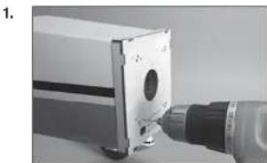
natural_image
Close-up of a mechanical component with a drill bit and circular opening (no visible text or symbols)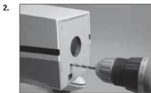
natural_image
Close-up of a mechanical component with a drill bit inserted, no visible text or symbols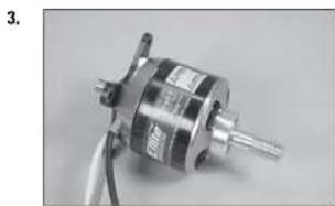
natural_image
Close-up of a metallic mechanical component with wires and shafts (no visible text or symbols)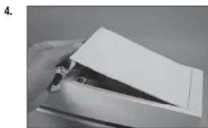
natural_image
Hand holding a piece of paper or paper with a triangular cutout (no visible text or symbols)natural_image
White rectangular object with a recessed oval cutout, placed on a plain surface (no text or symbols visible)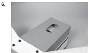
natural_image
Close-up of a metallic mechanical component with a recessed slot and mounting holes (no visible text or symbols)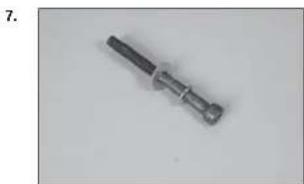
natural_image
Close-up of a metallic screwdriver with a black handle and threaded shaft (no text or symbols visible)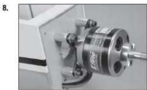
natural_image
Close-up of a mechanical assembly with a metallic cylindrical component and a threaded shaft (no visible text or symbols)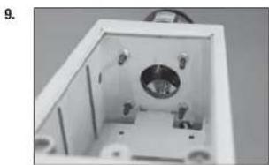
natural_image
Interior view of a white rectangular enclosure with internal components and mounting holes (no visible text or symbols)natural_image
Interior view of a mechanical or electrical enclosure with no visible text or symbols11.
natural_image
Close-up of a white plastic electrical connector with black connectors and mounting holes (no text or symbols visible)12.

natural_image
Close-up of a mechanical device with internal components and mounting holes (no visible text or symbols)13.

natural_image
Exterior view of a white electronic device casing with internal components (no visible text or symbols)14.

natural_image
Interior view of an electronic device with visible wiring and components (no text or symbols)natural_image
Exterior view of a white electronic device with a small black component on top (no visible text or symbols)16.

natural_image
Close-up of a mechanical component with a metallic cylindrical assembly and a central shaft (no visible text or symbols)17.
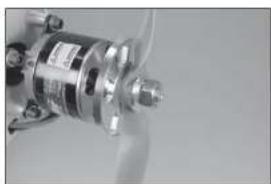
natural_image
Close-up of a metallic mechanical component with no visible text or symbols18.

natural_image
Close-up of a metallic conical object with a protruding rod (no visible text or symbols)1.
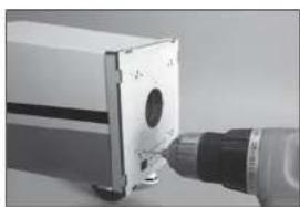
natural_image
Close-up of a mechanical component with a cylindrical tool inserted, no visible text or symbolsnatural_image
Close-up of a mechanical tool with a drill bit inserted into a small block (no visible text or symbols)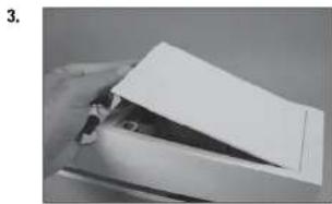
natural_image
Close-up of a hand holding a piece of paper or paper with a triangular tip, no visible text or symbols
natural_image
Metal mechanical component with cylindrical shaft and flanged end (no visible text or symbols)
natural_image
Close-up of a white industrial machine with a coiled component, no visible text or symbols
natural_image
Close-up of a mechanical component with internal parts and a metallic bracket (no visible text or symbols)natural_image
Close-up of a mechanical device with components and wiring (no visible text or symbols)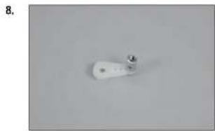
natural_image
Close-up of a white cylindrical object with a small metallic protrusion on a plain gray background (no text or symbols visible)
natural_image
Close-up of a finger holding a small electronic component (no visible text or symbols)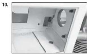
natural_image
Interior view of a white electronic device with a circular component and internal components (no visible text or symbols)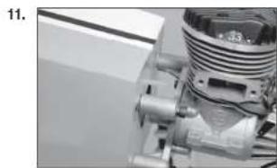
natural_image
Close-up of a mechanical assembly with no visible text or symbolsnatural_image
Close-up of a black electrical plug with three leads, no text or symbols visible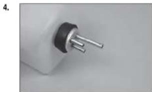
natural_image
Close-up of a small electronic component with metallic pins (no visible text or symbols)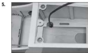
natural_image
Interior view of a device housing with visible wiring and components (no text or symbols)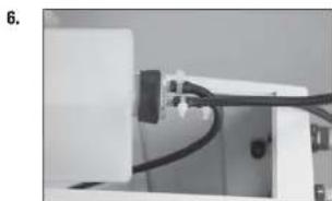
natural_image
Close-up of a mechanical or electronic component with wires and connectors (no visible text or symbols)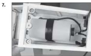
natural_image
Interior view of a device showing internal components and wiring (no visible text or symbols)natural_image
Close-up of industrial machinery components with hoses and tubing (no visible text or symbols)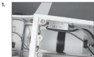
natural_image
Close-up of a mechanical or electronic component with wires and a black rectangular component (no visible text or symbols)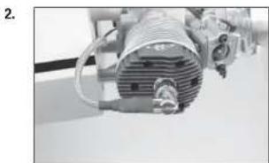
natural_image
Close-up of industrial machinery with coiled components and wiring (no visible text or symbols)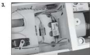
natural_image
Interior view of an electronic device showing internal components and wiring (no visible text or symbols)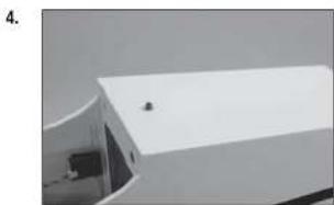
natural_image
Exterior view of a modern building with a white roof and small window (no signage or text visible)DER SCHWERPUNKT
□ RUDERAUSSCHLAG
Links: 70mm Links: 35mm
Klappen:
Mitte: 25mm Landung: 55mm
natural_image
Close-up of a thin, elongated object with a metallic tool inserted, possibly a tool or tool, against a plain background (no visible text or symbols)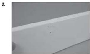
natural_image
Close-up of a white rectangular object with a small mark and dot on top (no text or symbols visible)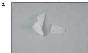
natural_image
Two irregular white fragments on a plain gray background, no text or symbols visible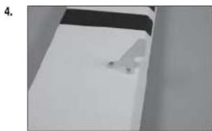
natural_image
Close-up of a white surface with a small white object on the right side (no text or symbols visible)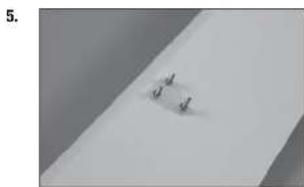
natural_image
Close-up of a white surface with a small, dark, and light spot on the left side (no text or symbols visible)natural_image
Close-up of a hand holding a pliers near a small object on a white surface (no text or symbols visible)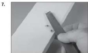
natural_image
Close-up of a hand holding a metal tool with small dark fragments, against a plain white background (no text or symbols visible)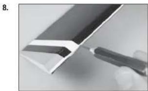
natural_image
Close-up of a metallic tool interacting with a white panel edge (no text or symbols visible)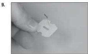
natural_image
Close-up of a hand holding a small white plastic clip (no text or symbols visible)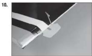
natural_image
Close-up of a white aircraft wing with a flag, against a dark sky background (no text or symbols visible)natural_image
White rectangular object with black top and small protrusions, possibly a battery or sensor component (no visible text or symbols)12.

natural_image
Close-up of a white rectangular object with a small mark and faint lines, possibly a document or paper (no visible text or symbols)13.
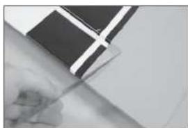
natural_image
Close-up of a hand holding a pen, partially covered by a black-and-white flag (no visible text or symbols)14.
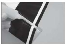
natural_image
Close-up of a hand holding a black rectangular object with white diagonal lines, possibly part of a device or component (no visible text or symbols)15.

natural_image
Close-up of a white plastic sheet with a black 'STICK' logo on top, showing a small crack (no readable text or symbols beyond the logo)natural_image
Close-up of a hand holding a pen writing on a white sheet of paper (no visible text or symbols)2.
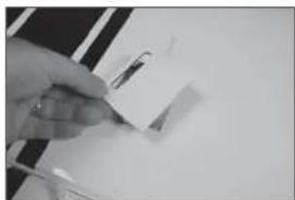
natural_image
Close-up of a hand holding a small object with a pen, against a plain white background (no visible text or symbols)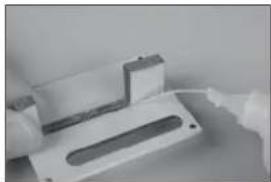
natural_image
Close-up of a white plastic electronic component with a recessed slot, possibly a switch or connector (no visible text or symbols)3.
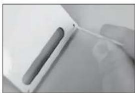
natural_image
Close-up of a hand holding a white electronic device with a cable (no visible text or symbols)4.
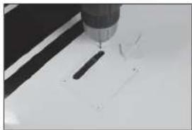
natural_image
Close-up of a precision tool tip cutting through a white surface (no text or symbols visible)natural_image
Close-up of a metallic object with a suspended rod and triangular base, no visible text or symbols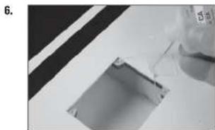
natural_image
Close-up of a mechanical component with a glass pouring liquid into a rectangular slot (no visible text or symbols)
natural_image
Close-up of a hand holding a small metal wire tool (no visible text or symbols)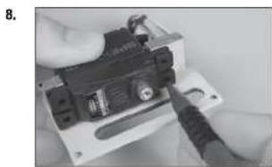
natural_image
Close-up of hands installing a small electronic component with a tool (no visible text or symbols)
natural_image
Close-up of a mechanical component with a pointed tool inserted, no visible text or symbolsnatural_image
Close-up of a black electronic device with labeled components, possibly an optical or mechanical component (no readable text or symbols)
natural_image
Close-up of a hand holding a small electronic device with a black clip attached (no visible text or symbols)
natural_image
Close-up of a hand holding a small black electronic component with wires, no visible text or symbols
natural_image
Close-up of a hand holding a small electronic component (no visible text or symbols)
natural_image
Close-up of a gloved hand holding a small circular object with a string, against a plain background (no text or symbols visible)natural_image
Simple diagram of a mechanical component with four circular holes and a central rod, placed on a plain surface (no text or symbols)16.
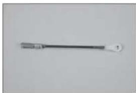
natural_image
Simple line drawing of a tool or probe with a handle and tip (no text or symbols)17.
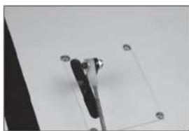
natural_image
Close-up of a mechanical clamp or bracket with four circular holes, no visible text or symbols18.
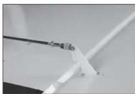
natural_image
Close-up of a white plastic sheet with a black metal rod inserted, no visible text or symbols19.
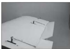
natural_image
Close-up of a white sheet with small black markers and a small figure on the page (no visible text or symbols)natural_image
Exterior view of a modern office building (no signage)21.

natural_image
Close-up of a white sheet with a small object and two small markers, possibly a document or paper piece (no visible text or symbols)1.

natural_image
Close-up of a metallic electronic component with a black tab and multiple holes (no visible text or symbols)2.
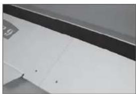
natural_image
Close-up of a white cabinet or shelf with black and white panels, no visible text or symbols3.
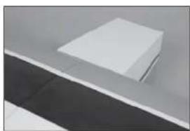
natural_image
Minimalist abstract image showing a white rectangular object placed on a gray surface with a dark horizontal stripe below (no text or symbols)natural_image
Simple line drawing of a symmetrical geometric shape resembling a trapezoidal frame or container (no text or symbols)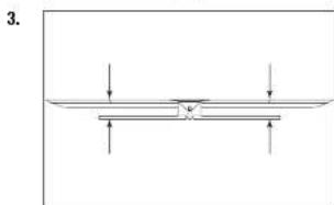
natural_image
Pure diagram of a horizontal beam with downward force arrows, no text or symbols present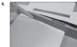
natural_image
Close-up of a hand holding papers or documents, no visible text or symbolsnatural_image
Close-up of a mechanical assembly with metal brackets and paper sheets (no visible text or symbols)1.

natural_image
Close-up of a hand measuring a cylindrical object with a ruler, no visible text or symbols2.

3.
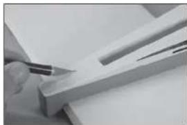
natural_image
Close-up of a hand using a pen to cut or mark a piece of wood or metal (no visible text or symbols)4.
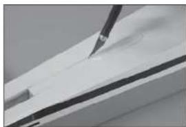
natural_image
Close-up of a white surface with a black tool applying material to the top layer (no text or symbols visible)natural_image
Close-up of a hand holding a ruler and eraser over a white rectangular object, with no visible text or symbols.6.

natural_image
Close-up of a hand holding a pen over a sheet of paper (no visible text or symbols)7.
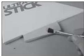
natural_image
Close-up of a paintbrush applying black paint to a white plastic sheet with 'ULTRA STICK' branding (no other text or symbols visible)8.

natural_image
Close-up of a hand using a ruler to write on a white surface, with a partial view of a white box labeled 'ULT ST' visible (no readable text or symbols)1.

natural_image
Close-up of a white rectangular electronic component with a small metallic tip, placed on a plain gray surface (no text or symbols visible)natural_image
Close-up of a ceiling structure with diagonal white lines and dark gray panels (no text or symbols visible)
natural_image
Close-up of a folded paper or plastic sheet with black and white stripes, no visible text or symbols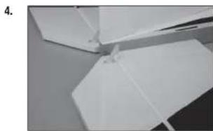
natural_image
Close-up of white paper folding panels on a surface (no text or symbols visible)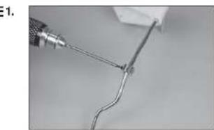
natural_image
Close-up of a wire being held by a tool, showing a curved wire or wire with a metallic tip (no text or symbols visible)
natural_image
Close-up of a hand holding a metal clip attached to a white sheet of paper (no text or symbols visible)natural_image
Close-up of a hand holding a white cable with a small black mark, against a plain background (no text or symbols visible)
natural_image
Close-up of hands holding a thin, white wire or filament against a plain background (no text or symbols visible)
natural_image
Close-up of a white plastic sheet being cut with a metal clip, showing texture and surface details (no text or symbols visible)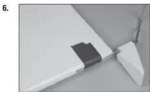
natural_image
Close-up of a white plastic component with a black rectangular clip attached, no visible text or symbols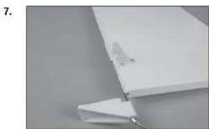
natural_image
Close-up of a white plastic sheet with a small metallic clip attached, against a plain gray background (no text or symbols visible)natural_image
Close-up of hands holding a thin wire or cable with a white plastic component, no visible text or symbols10.

natural_image
Close-up of a mechanical component with angled surfaces and mounting holes (no visible text or symbols)11.

natural_image
Close-up of a white mechanical component with a curved rod and triangular base (no visible text or symbols)12.

natural_image
Close-up of a small mechanical component with a circular head and metallic shaft (no visible text or symbols)INSTALLATION RADIO
2.
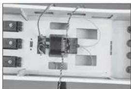
natural_image
Interior view of a device with labeled ports and wiring (no readable text or symbols)3.

natural_image
Close-up of electronic devices with cables and connectors (no visible text or symbols)4.

natural_image
Close-up of a mechanical component with wires and connectors (no visible text or symbols)5.
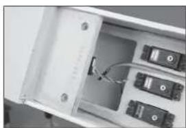
natural_image
Interior view of an open electronic device showing internal components and wiring (no visible text or symbols)natural_image
Interior view of a white filing cabinet with multiple black electronic components (no visible text or labels)7.

natural_image
Interior view of a refrigerator drawer showing internal compartments and storage racks (no visible text or labels)8.

natural_image
Top-down view of an electronic device cluster with multiple ports and connectors (no visible text or symbols)9.

natural_image
Close-up of a white vehicle's side panel with a black cable and a small mark, no visible text or symbolsnatural_image
Close-up of a small mechanical component with a cylindrical head and a wire, no visible text or symbols.11.
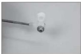
natural_image
Close-up of a small white object with a metallic rod extending from it, against a plain background (no text or symbols visible)12.

natural_image
Interior view of an electronic device casing with multiple components and wiring (no visible text or symbols)13.
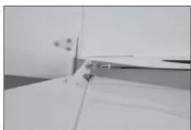
natural_image
Close-up of a white cabinet or shelf with a metal clip inserted, no visible text or symbols14.

natural_image
Close-up of a white ceiling shelf with a small black electrical outlet (no visible text or symbols)natural_image
Close-up of a metallic medical or laboratory tool with a pointed tip and handle (no visible text or symbols)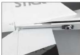
natural_image
Close-up of a white electronic device with a metallic connector and paper sheet (no visible text or symbols)
natural_image
Close-up of a hand holding a screwdriver (no visible text or symbols)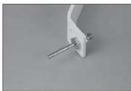
natural_image
Close-up of a white mechanical clamp or bracket with a metal rod inserted (no visible text or symbols)
natural_image
Close-up of a white mechanical clamp or bracket with metal pins (no visible text or symbols)natural_image
Close-up of a mechanical tool with a circular dial and textured handle (no visible text or symbols)
natural_image
Close-up of a mechanical component with a curved arm and a black circular base (no visible text or symbols)
natural_image
Close-up of a hand holding a small object on a flat surface (no visible text or symbols)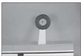
natural_image
Close-up of a circular mechanical component mounted on a stand (no visible text or symbols)
natural_image
Close-up of a white mechanical component with four black holes, possibly part of a fan or wing (no text or symbols visible)natural_image
Interior view of an electrical enclosure showing a motor or electrical component with no visible text or symbols11.

natural_image
Close-up of a white plastic electrical connector with black connectors and mounting holes (no text or symbols visible)12.

natural_image
Close-up of a mechanical device with internal components and mounting holes (no visible text or symbols)13.
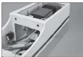
natural_image
Exterior view of a white electronic device casing with internal components (no visible text or symbols)14.
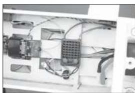
natural_image
Interior view of an electronic device with visible wiring and components (no text or symbols)natural_image
Exterior view of a modern office building (no signage)16.

natural_image
Close-up of a mechanical component with a metallic cylindrical assembly and a transparent housing (no visible text or symbols)17.

natural_image
Close-up of a metallic mechanical component with no visible text or symbols18.

natural_image
Close-up of a metallic conical object with a label, possibly a missile or projectile (no visible text or symbols)1.

natural_image
Close-up of a mechanical device with a cylindrical component and a metallic tool inserted (no visible text or symbols)natural_image
Close-up of a mechanical tool applying material to a small cylindrical component (no visible text or symbols)
natural_image
Close-up of a hand holding a white paper airplane wing, no visible text or symbols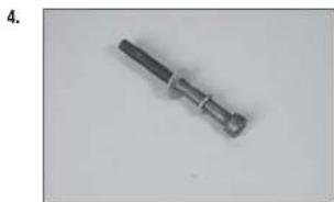
natural_image
Metal mechanical component with a cylindrical shaft and flanged end (no visible text or symbols)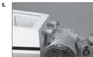
natural_image
Close-up of a mechanical device with visible components and no readable text or symbols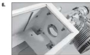
natural_image
Close-up of a mechanical component with internal parts and a metallic housing (no visible text or symbols)natural_image
Interior view of a laboratory instrument with labeled components (no visible text or symbols)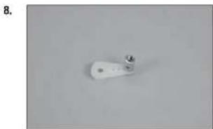
natural_image
White cylindrical object with a small protrusion on top, placed on a plain gray surface (no text or symbols visible)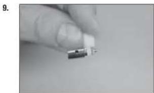
natural_image
Close-up of a hand holding a small electronic component (no visible text or symbols)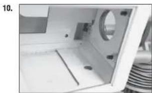
natural_image
Interior view of a white appliance with a circular vent and internal components (no visible text or symbols)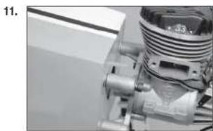
natural_image
Close-up of a mechanical component with threaded and threaded parts (no visible text or symbols)DÉBATTEMENTS
Haut: 68mm Haut: 30mm
Bas : 55mm Bas : 25mm
Haut: 55mm Haut: 27mm
Bas : 55mm Bas : 27mm
□ CHECKLIST D'AVANT VOL
natural_image
Close-up of a hand holding a tool next to a white rectangular object (no visible text or symbols)2.

natural_image
Close-up of a white rectangular object with a small mark on the surface (no visible text or symbols)3.

natural_image
Two irregular white fragments on a plain gray background (no text or symbols)4.
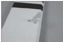
natural_image
Exterior view of a modern office building (no signage)5.

natural_image
Close-up of a small metallic object on a plain surface (no visible text or symbols)natural_image
Close-up of a gloved hand holding a pliers near a small object on a white surface (no text or symbols visible)7.
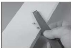
natural_image
Close-up of a hand holding a metal tool with small dark fragments, resting on a plain surface (no text or symbols visible)8.

natural_image
Close-up of a metallic tool interacting with a white panel or sheet metal (no visible text or symbols)9.

natural_image
Close-up of a hand holding a small white plastic clip (no text or symbols visible)10

natural_image
Close-up of a white aircraft wing with a visible propeller and arrow (no text or symbols)natural_image
White rectangular object with a black top, possibly a battery or scanner (no visible text or symbols)12.

natural_image
Close-up of a white rectangular object with a small mark and a faint horizontal line, placed on a dark surface (no text or symbols visible)13.

natural_image
Close-up of a hand holding a pen, with a black-and-white flag patch partially visible (no text or symbols)14.

natural_image
Close-up of a hand holding a dark rectangular object with a white cross-shaped mark, against a plain background (no text or symbols visible)15.

natural_image
Close-up of a white plastic sheet with a visible crack and 'STICK' logo on top (no other text or symbols)natural_image
Close-up of a hand holding a white sheet with a knife, no visible text or symbols1.

natural_image
Close-up of a hand holding a small object on a white surface, possibly a tool or device (no visible text or symbols)2.
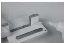
natural_image
Close-up of a white plastic electronic component with a slot and mounting holes (no visible text or symbols)3.
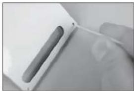
natural_image
Close-up of a hand holding a white electronic device with a cable (no visible text or symbols)4.
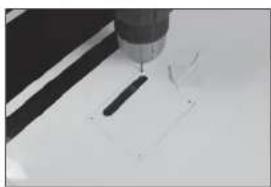
natural_image
Close-up of a precision tool tip cutting a white surface with a black tool (no text or symbols visible)natural_image
Close-up of a metallic object with a suspended rod and triangular base, no visible text or symbols
natural_image
Close-up of a mechanical component with a glass pouring liquid into a rectangular slot (no visible text or symbols)
natural_image
Close-up of a hand holding a small metal wire tool (no visible text or symbols)
natural_image
Close-up of hands installing a small electronic component with a tool (no visible text or symbols)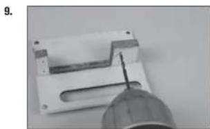
natural_image
Close-up of a mechanical component with a pointed tool inserted, no visible text or symbolsnatural_image
Close-up of a black electronic device with labeled components, possibly an optical or mechanical component (no readable text or symbols)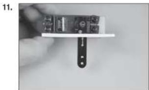
natural_image
Close-up of a hand holding a small electronic device with a black clip attached (no visible text or symbols)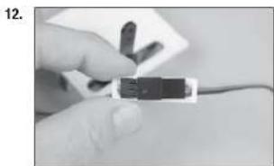
natural_image
Close-up of a hand holding a small black electronic component with wires, no visible text or symbols
natural_image
Close-up of a hand holding a small electronic component (no visible text or symbols)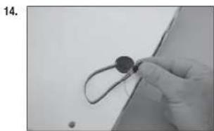
natural_image
Close-up of a gloved hand holding a small circular object with a string, against a plain background (no text or symbols visible)natural_image
Simple line drawing of a mechanical part with four circular holes and a central square outline (no text or symbols)16.

natural_image
Simple line drawing of a tool or probe with a pointed tip and handle (no text or symbols)17.

natural_image
Close-up of a mechanical clamp or bracket with mounting holes, mounted on a plain surface (no text or symbols visible)18.
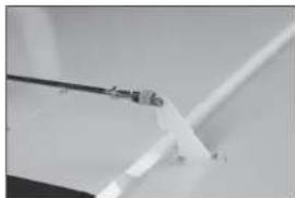
natural_image
Close-up of a white plastic or metal component with a thin wire, possibly a tool or bracket (no visible text or symbols)19.
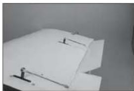
natural_image
Close-up of a white paper sheet with small black markers, no visible text or symbolsnatural_image
Close-up of a white plastic sheet with metal clamps (no visible text or symbols)21.
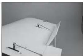
natural_image
Close-up of a white sheet with small black connectors and a small figure, against a plain background (no text or symbols visible)1.
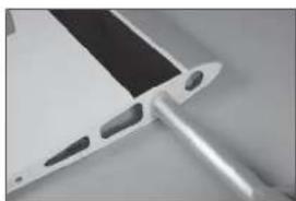
natural_image
Close-up of a metallic electronic component with a black tab and a metallic rod (no visible text or symbols)2.

natural_image
Close-up of a white surface with black and gray edges, no visible text or symbols3.

natural_image
Minimalist abstract image showing a white rectangular object placed on a dark surface with a horizontal line (no text or symbols)natural_image
Abstract geometric shapes with diagonal lines and triangular forms (no text or symbols)1.
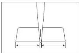
natural_image
Pure geometric diagram showing a V-shaped structure with two horizontal segments and a vertical line above (no text or symbols)2.
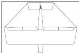
natural_image
Simple line drawing of a symmetrical geometric shape with no text or symbols3.
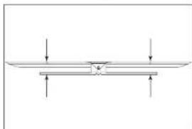
natural_image
Pure mechanical diagram showing a beam supported by two supports with downward force arrows (no text or symbols)4.
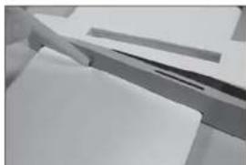
natural_image
Close-up of a white surface with a dark horizontal band and a small black mark, no visible text or symbols.6.

natural_image
Close-up of a hand holding a small object against a plain background (no visible text or symbols)7.
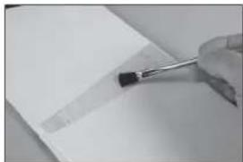
natural_image
Close-up of a hand holding a small tool near a blank sheet of paper (no visible text or symbols)8.
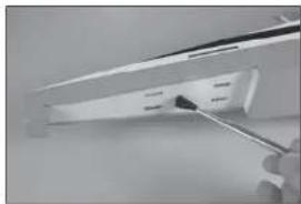
natural_image
Close-up of a hand using a screwdriver to apply black plastic components on a white shelf (no text or symbols visible)9.
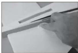
natural_image
Close-up of a hand holding a pen over a blank sheet of paper (no visible text or symbols)natural_image
Close-up of a mechanical assembly with metal brackets and paper sheets (no visible text or symbols)1.

natural_image
Close-up of a hand measuring a cylindrical object with a ruler, no visible text or symbols2.

3.
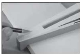
natural_image
Close-up of a hand using a pen to cut or mark a wooden plank (no visible text or symbols)4.

natural_image
Close-up of a white surface with a black pen inserted, showing texture and shading (no text or symbols visible)natural_image
Close-up of a hand using a ruler to cut a white rectangular object, with no visible text or symbols.6.

natural_image
Close-up of a hand holding a pen over a sheet of paper (no visible text or symbols)7.
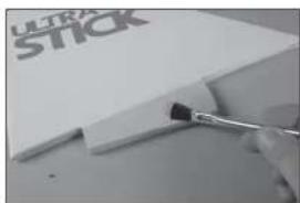
natural_image
Close-up of a hand holding a paintbrush applying paint to a white paper with 'ULTRA STICK' branding (no other text or symbols visible)8.
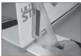
natural_image
Close-up of a hand using a ruler to cut or mark a white object, with no visible text or symbols.1.
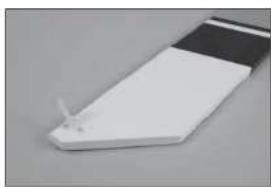
natural_image
Close-up of a white electronic component with a small metallic tip, possibly a sensor or connector (no visible text or symbols)natural_image
Close-up of a ceiling structure with diagonal white lines and dark gray panels (no text or symbols visible)
natural_image
Close-up of a folded paper or plastic sheet with black and white stripes, no visible text or symbols
natural_image
Close-up of white paper folding fragments on a surface (no text or symbols visible)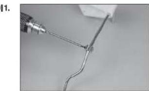
natural_image
Close-up of a wire being held by a tool, showing a curved wire or wire with a metallic tip (no text or symbols visible)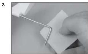
natural_image
Close-up of a hand holding a metal clip attached to a white sheet of paper (no text or symbols visible)natural_image
Close-up of a hand holding a white cable with a small black mark, against a plain background (no text or symbols visible)
natural_image
Close-up of hands holding a thin, white wire or filament against a plain background (no text or symbols visible)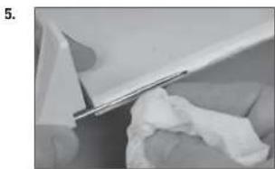
natural_image
Close-up of a white plastic sheet being folded or damaged, with no visible text or symbols
natural_image
Close-up of a white plastic component with a black rectangular clip attached, no visible text or symbols
natural_image
Close-up of a white plastic sheet with a small metallic clip attached, against a plain gray background (no text or symbols visible)natural_image
Close-up of hands holding a small white object with black dots, possibly part of a device or tool (no visible text or symbols)10.
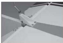
natural_image
Close-up of a mechanical component with no visible text or symbols11.

natural_image
Close-up of a white mechanical component with a curved bracket and mounting base (no visible text or symbols)12.
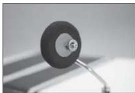
natural_image
Close-up of a black circular object mounted on a stand, possibly a knob or dial, against a blurred background (no text or symbols visible)natural_image
Interior view of a computer case with labeled ports and cables (no text or symbols visible)2.
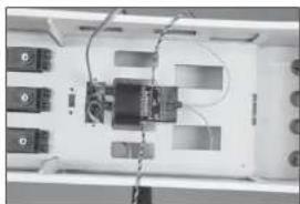
natural_image
Interior view of a device with labeled ports and wiring (no readable text or symbols)3.
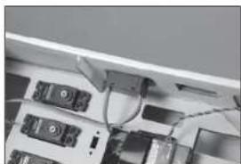
natural_image
Close-up of electronic devices and cables in a rack (no visible text or symbols)4.
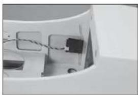
natural_image
Close-up of a white plastic container with internal compartments and a black plastic component (no visible text or symbols)5.
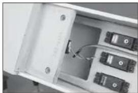
natural_image
Interior view of an open electronic device showing internal components and a cable (no visible text or symbols)natural_image
Interior view of a white filing cabinet with multiple black electronic components (no visible text or labels)7.

natural_image
Interior view of a refrigerator drawer showing internal compartments and storage racks (no visible text or labels)8.

natural_image
Top-down view of an electronic device cluster with multiple ports and connectors (no visible text or symbols)9.

natural_image
Close-up of a white mechanical component with a black cable and a small protrusion (no visible text or symbols)natural_image
Close-up of a small mechanical component with a cylindrical head and a wire, no visible text or symbols.11.

natural_image
Close-up of a small white object with a metallic rod attached to a circular base, against a plain background (no text or symbols visible)12.

natural_image
Interior view of an electronic device casing with multiple circuit breakers and connectors (no visible text or labels)13.

natural_image
Close-up of a white door with a small handle and a small object on the side (no visible text or symbols)14.

natural_image
Close-up of a white ceiling shelf with a small black electrical outlet (no visible text or symbols)natural_image
Metal tool with a pointed tip and handle, isolated on white background (no text or symbols)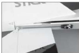
natural_image
Close-up of a white electronic device with a metallic connector and paper clip (no visible text or symbols)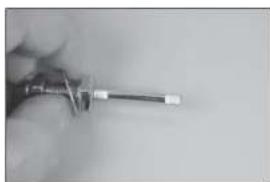
natural_image
Close-up of a hand holding a screwdriver (no visible text or symbols)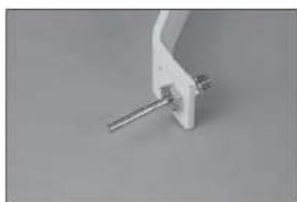
natural_image
Close-up of a white mechanical clamp or bracket with metal pins (no visible text or symbols)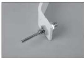
natural_image
Close-up of a white mechanical clamp or bracket with a metal rod inserted (no visible text or symbols)natural_image
Close-up of a mechanical tool with a circular component and textured handle (no visible text or symbols)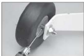
natural_image
Close-up of a small aircraft landing gear with visible hub and mounting bracket (no text or symbols)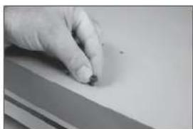
natural_image
Close-up of a hand holding a small object on a flat surface (no visible text or symbols)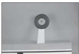
natural_image
Close-up of a circular mechanical component mounted on a stand, no visible text or symbols
natural_image
Close-up of a white mechanical component with four black holes, possibly part of a fan or wing (no text or symbols visible)natural_image
Interior view of a mechanical or electrical enclosure with no visible text or symbols11.

natural_image
Close-up of a white plastic electrical connector with black connectors and mounting holes (no text or symbols visible)12.
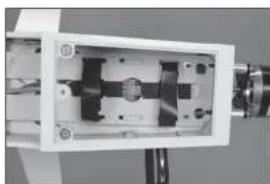
natural_image
Close-up of a mechanical device with internal components and mounting holes (no visible text or symbols)13.

natural_image
Exterior view of a white electronic device casing with internal components (no visible text or symbols)14.

natural_image
Interior view of an electronic device with visible wiring and components (no text or symbols)natural_image
Exterior view of a modern office building (no signage)16.
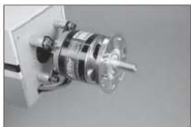
natural_image
Close-up of a mechanical component with a metallic cylindrical assembly and a transparent housing (no visible text or symbols)17.

natural_image
Close-up of a metallic mechanical component with no visible text or symbols18.

natural_image
Close-up of a metallic conical object with a label, possibly a missile or projectile (no visible text or symbols)1.
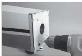
natural_image
Close-up of a mechanical component with a cylindrical part inserted, connected to a tool (no visible text or symbols)natural_image
Close-up of a mechanical tool with a drill bit inserted into a box (no visible text or symbols)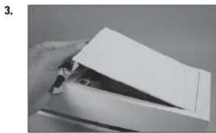
natural_image
Close-up of a hand holding a piece of paper or paper with a triangular cutout (no visible text or symbols)
natural_image
Close-up of a metallic screwdriver with a black handle and threaded shaft (no text or symbols visible)
natural_image
Close-up of a mechanical device with a coiled spring and control panel (no visible text or symbols)
natural_image
Close-up of a mechanical component with internal parts and a metallic bracket (no visible text or symbols)natural_image
Close-up of a mechanical device with components and wiring (no visible text or symbols)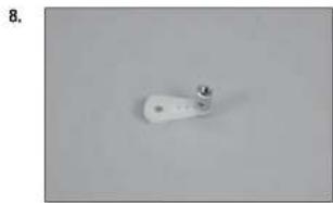
natural_image
Close-up of a white cylindrical object with a small metallic protrusion on a plain gray background (no text or symbols visible)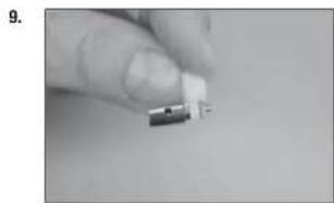
natural_image
Close-up of a finger holding a small electronic component (no visible text or symbols)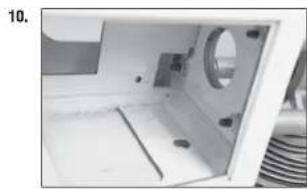
natural_image
Interior view of a white plastic enclosure with a circular vent and side compartments (no text or symbols visible)
natural_image
Close-up of a mechanical component with threaded shaft and mounting flange (no visible text or symbols)CORSE DEI COMANDI
© 2016 Horizon Hobby, LLC.
Hangar 9, Ultra Stick, Evolution, DSM, DSMX, PowerSafe, X-Plus, AS3X and the Horizon Hobby logo are trademarks or registered trademarks of Horizon Hobby, LLC. The Spektrum trademark is used with permission of Bachmann Industries, Inc.
All other trademarks, service marks and logos are the property of their respective owners.
51843.3 Updated 10/2017