Carbon Cub 15cc ARF - Remote control toy Hangar 9 - Free user manual and instructions
Find the device manual for free Carbon Cub 15cc ARF Hangar 9 in PDF.
Frequently Asked Questions - Carbon Cub 15cc ARF Hangar 9
User questions about Carbon Cub 15cc ARF Hangar 9
0 question about this device. Answer the ones you know or ask your own.
Ask a new question about this device
Download the instructions for your Remote control toy in PDF format for free! Find your manual Carbon Cub 15cc ARF - Hangar 9 and take your electronic device back in hand. On this page are published all the documents necessary for the use of your device. Carbon Cub 15cc ARF by Hangar 9.
USER MANUAL Carbon Cub 15cc ARF Hangar 9
All instructions, warranties and other collateral documents are subject to change at the sole discretion of Horizon Hobby, LLC. For up-to-date product literature, visit horizonhobby.com and click on the support tab for this product. The following terms are used throughout the product literature to indicate various levels of potential harm when operating this product:
Meaning of Special Language
NOTICE: Procedures, which if not properly followed, create a possibility of physical property damage AND a little or no possibility of injury.
CAUTION: Procedures, which if not properly followed, create the probability of physical property damage AND a possibility of serious injury.
WARNING: Procedures, which if not properly followed, create the probability of property damage, collateral damage, and serious Injury OR create a high probability of superflial injury.
WARNING: Read the ENTIRE instruction manual to become familiar with the features of the product before operating. Failure to operate the product correctly can result in damage to the product, personal property and cause serious injury.
This is a sophisticated hobby product. It must be operated with caution and common sense and requires some basic mechanical ability. Failure to operate this Product in a safe and responsible manner could result in injury or damage to the product or other property. This product is not intended for use by children without direct adult supervision. Do not attempt disassembly, use with incompatible components or augment product in any way without the approval of Horizon Hobby, LLC. This manual contains instructions for safety, operation and maintenance. It is essential to read and follow all the instructions and warnings in the manual, prior to assembly, setup or use, in order to operate correctly and avoid damage or serious injury.
AGE RECOMMENDATION: NOT FOR CHILDREN UNDER 14 YEARS. THIS IS NOT A TOY.
USING THE MANUAL
This manual is divided into sections to help make assembly easier to understand.
SAFETYWARNINGSANDPRECAUTIONS
Read and follow all instructions and safety precautions before use. Improper use can result in fire, serious injury and damage to property.
Components
Use only with compatible components. Should any compatibility questions exist, please refer to the product Instructions, component Instructions or contact the appropriate Horizon Hobby offi ce.
Flight
Fly only in open areas to ensure safety. It is recommended fl y ing be done at radio control fl y ing fi elds. Consult local ordinances before choosing a fl y ing location.
Propeller
Keep loose items that can become entangled in the propeller away from the propit. This includes loose clothing or other objects such as pencils and screwdrivers. Keep your hands away from the propeller as injury can occur.
Batteries
Always follow the manufacturer's instructions when using and disposing of any batteries. Mishandling of Li-Po batteries can result in fl re causing serious injury and damage.
Small Parts
This kit includes small parts and should not be left unattended near children as choking and serious injury could result.
SAFE OPERATING RECOMMENDATIONS
- Inspect your model before every flight to ensure it is airworthy.
- Be aware of any other radio frequency user who may present an interference problem.
Always be courteous and respectful of other users in your selected flight area. - Choose an area clear of obstacles and large enough to safely accommodate your fl ying activity.
Make sure this area is clear of friends and spectators prior to launching your aircraft. - Be aware of other activities in the vicinity of your flight path that could cause potential conflict.
- Carefully plan your flight path prior to launch.
Abide by any and all established AMA National Model Aircraft Safety Code.
BEFORE STARTING ASSEMBLY
- Remove parts from bag.
- Inspect fuselage, wing panels, rudder and stabilizer for damage.
If you find damaged or missing parts, contact your place of purchase.
If you fi nd any wrinkles in the covering, use a heat gun (HAN100) and covering glove (HAN150) or covering iron (HAN101) with a sealing iron sock (HAN141) to remove them. Use caution while working around areas where the colors overlap to prevent separating the colors.
- Charge transmitter and receiver batteries.
Center trims and sticks on your transmitter.
For a computer radio, create a model memory for this particular model. - Bind your transmitter and receiver, using your radio system's instructions.
IMPORTANT: Rebind the radio system once all control throws are set. This will keep the servos from moving to their endpoints until the transmitter and receiver connect. It will also guarantee the servo reversal settings are saved in the radio system.
HINWEIS
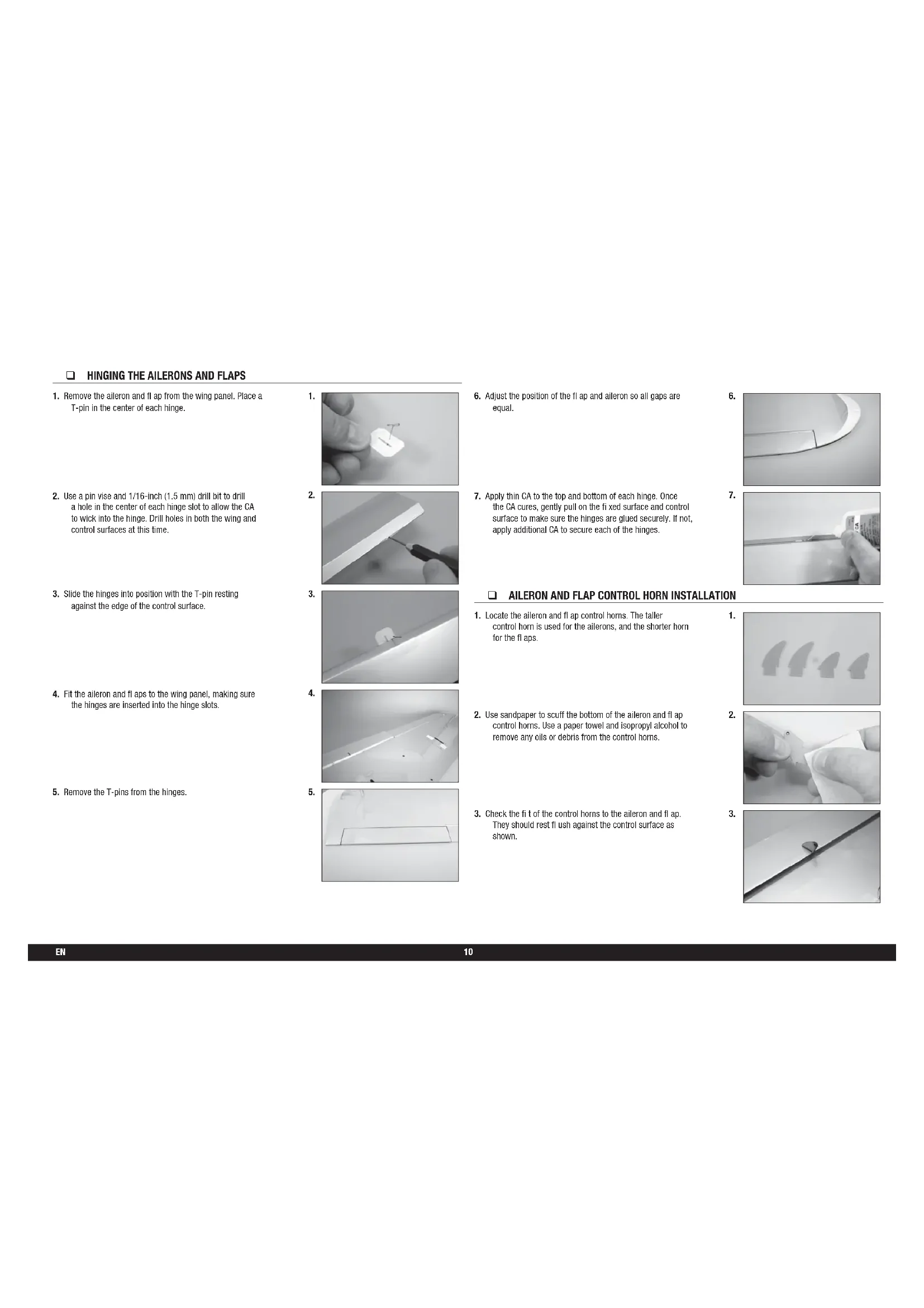
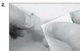
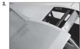
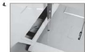
- Remove the aileron and flap from the wing panel. Place a T-pin in the center of each hinge.
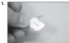
- Use a pin vise and 1/16-inch (1.5 mm) drill bit to drill a hole in the center of each hinge slot to allow the CA to wick into the hinge. Drill holes in both the wing and control surfaces at this time.
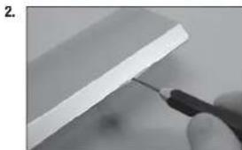
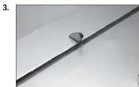
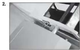
- Slide the hinges into position with the T-pin resting against the edge of the control surface.
- Fit the aileron and fl aps to the wing panel, making sure the hinges are inserted into the hinge slots.
- Remove the T-pins from the hinges.
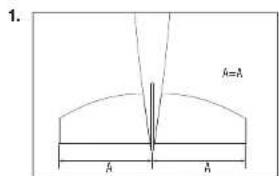
- Adjust the position of the flap and aileron so all gaps are equal.
- Apply thin CA to the top and bottom of each hinge. Once the CA cures, gently pull on the fi xed surface and control surface to make sure the hinges are glued securely. If not, apply additional CA to secure each of the hinges.
AILERON AND FLAP CONTROL HORN INSTALLATION
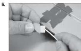
- Locate the alleron and fl ap control horns. The taller control horn is used for the allerons, and the shorter horn for the fl aps.
- Use sandpaper to scuff the bottom of the aileron and fit control horns. Use a paper towel and isopropyl alcohol to remove any oils or debris from the control horns.
- Check the fi t of the control horns to the alleron and fl ap. They should rest f1ush against the control surface as shown.

AILERON SERVO INSTALLATION
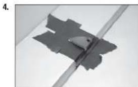
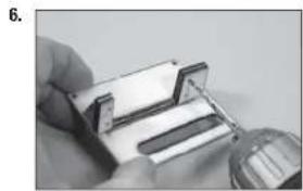
- Place low-tack tape 1/32 inch (1 mm) from the control horn slot. This will prevent epoxy from getting on the control surface when the control horns are glued in place.
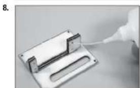
- Remove the control horns from the control surfaces. Apply epoxy to the slot in the alleron and fl ap. Make sure the epoxy gets into the slot for a good bond between the surfaces and control horn.
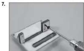
- Apply epoxy to the area of the control horns that fit into the slots. Use enough epoxy so the control horns will be fully bonded to the fixed surfaces.
- Fit of the control horns back into position. Check that they are square to the surface as shown.
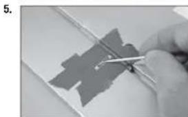
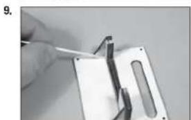
- Before the epoxy fully cures, remove the tape from around the control horn. This will allow the epoxy to flow around the control horn, creating a small fillet between the control horn and surface for a finished look and secure bond.
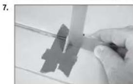
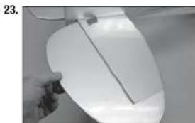
- Remove the aileron and fl ap cover from the wing. Use a toothpick to puncture the covering to locate the holes for the aileron and fl ap cover screws.
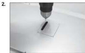
- Place the alieron and flap cover into position. Use a drill and 1/16-inch (1.5mm) drill bit to drill the holes in the servo cover mounts.
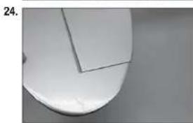
- Thread an M2 x 12 self-tapping screw into each of the holes in the alleron and fl ap servo cover mounting holes. Remove the screws before proceeding.
- Apply a small amount of thin CA to harden the threads made in the previous step. Allow the CA to fully cure before installing the aliron servo cover.
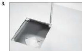
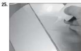
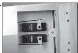
- Fit the servo between the servo mounting tabs in the alleron servo tray. The servo arm will be centered in the slot. Mark the locations for the servo mounting screws using a pencil, then remove the servo.
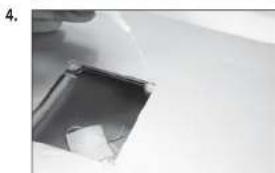
- Use a drill and a 1/16-inch (1.5mm) drill bit to drill the holes for the servo mounting screws in the locations marked in the previous step.
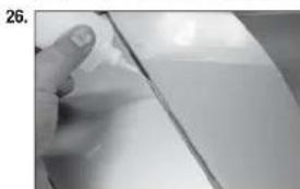
- Use a 2mm hex wrench to thread a servo mounting screw into each of the holes in the aileron servo mounting holes. Remove the screws before proceeding.
- Apply a small amount of thin CA to harden the threads made in the previous step.
- Check that the servo mount is glued securely to the servo cover. If the mount is not secure, use a small amount of 15-minute epoxy to make sure the mount is securely fastened to the servo cover.
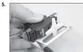
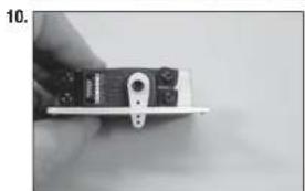
- Secure the servo to the cover using a 2mm hex wrench and the screws provided with the servo. Center the servos, then secure the servo arm so it is perpendicular to the servo centerline. Use side cutters to remove any arms that do not protrude to the outside of the cover.
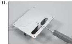
- Enlarge the outside hole in the aileron and fl ap servo arms using a pin visse and 5/64-inch (2mm) drill bit.
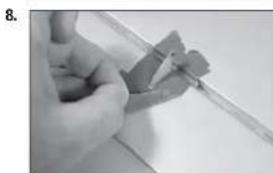
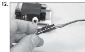
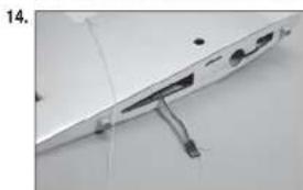
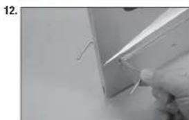
- Secure a 9-Inch (230mm) extension to the alleron servo lead using string or dental fit oss.
- Tie the string located inside the wing to the end of the servo lead.
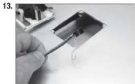
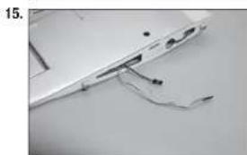
- Use the string to pull the servo lead through the opening at the wing root.
- Repeat the previous two steps to pull the fl ap servo lead to the wing root. The fl ap servo does not need an extension to reach the root of the wing panel.
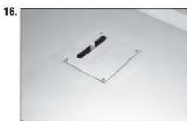
- Secure the aileron and flap covers in the wing using eight M2 x 12 self-tapping screws for each servo cover.
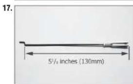
- Assemble the alleron linkage using a 4^ / s inch (111mm) pushrod and a metal clevis. Adjust the linkage to a length of 5% inches (130mm) to start. Use threadlock on all metal-to-metal fasteners to prevent them from vibrating loose.
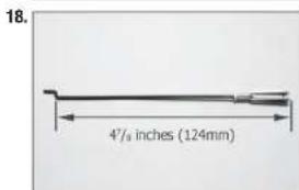
- Assemble the flap linkage using a 4-inch (111mm) pushrod and a metal clevis. Adjust the linkage to a length of 4^ / s inches (124mm) to start. Use threadlock on all metal-to-metal fasteners to prevent them from vibrating loose.
- Insert the Z-bend in the linkage into the servo horn. With the aileron servo centered, adjust the linkage so the aileron is centered when the clevis is attached to the control horn.
- Once the Linkage has been set, use needle nose pliers to tighten the nut against the clevis to prevent it from vibrating loose.
- Set the throw for the fl ap servo to 0% for both the up and down positions at the transmitter. Place the switch in the mid-flap position. Insert the Z-bend in the linkage into the servo horn.
- Adjust the linkage so the fl ap at the mid-flap setting of 25/32 inch (20mm) when the clevis is attached to the control horn. Once set, tighten the nut against the clevis to prevent it from vibrating loose.
- Move the fl ap switch to the up fi ap position. Adjust the throw at the transmitter until the fl ap is up and aligned with the trailing edge of the wing.
- Set the switch to the down fl ap position, and adjust the throw at the transmitter to achieve the throw of 1^15 / 6 inches (50mm).
WING INSTALLATION
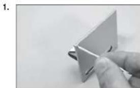
- Slide the wing tube into the wing tube socket.
- Slide the wing panel into position, guiding the extensions from the wing into the fuselage.
- Check that the wing fit ts tightly against the fuselage.
- Secure the wing panels to the fuselage using M3 x 12 socket head cap screws and M3 washers. Use a 2.5mm hex wrench to tighten the screws. Use a drop of canopy glue on the screw to prevent it from vibrating loose.
ELEVATOR AND STABILIZER INSTALLATION
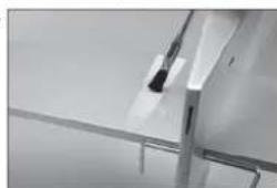
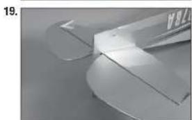
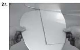
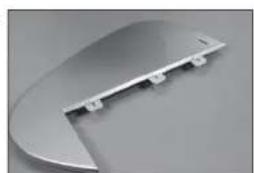
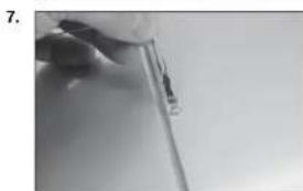
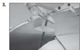
- Slide the stabilizer into the slot in the fuselage. Center the stabilizer.
- Measure from the tip of the stabilizer to the wing. Position the stabilizer so both measurements are equal. (Cowling has not been installed at this time.)
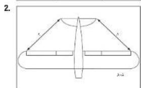
- Check the alignment of the stabilizer to the wing. It should be equal on both sides of the fuselage.
- Check all alignments. Mark the outline of the fuselage on the top and bottom of the stabilizer.
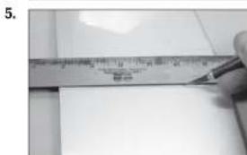
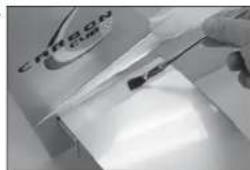
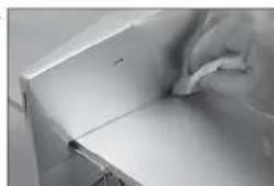
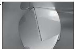
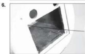
- Use a ruler and carefully cut the covering 1/8 inch (3 mm) inside the line drawn on the stabilizer to remove the covering from the center of the stabilizer. Remove the top and bottom covering. Use care not to cut into the underlying wood, weakening the stabilizer.
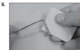
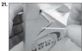
- Lightly sand the elevator joiner wire where it contacts the elevators. Use a paper towel and isopropyl alcohol to remove any oil or debris from the joiner.
- Fit the joiner wire into the elevator halves.

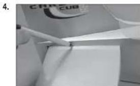
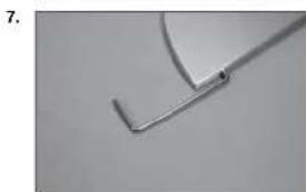
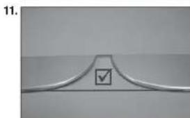
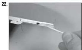
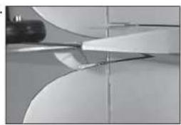
- The elevator joiner wire must be flush with the leading edge of the elevator as shown.
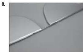
- Check to make sure the elevator halves are in alignment with each other.
- If the elevators are not in alignment, use pliers to bend the joiner wire slightly to bring the halves into alignment.
Poorly aligned elevators will cause problems with trimming your model in flight.
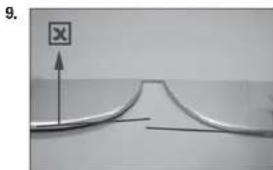
- Continue the assembly of your model once joiner wire has been correctly checked and adjusted.
- Remove the elevators from the joiner wire. Fit the joiner wire into the fuselage, noting the position from the previous step. This will guarantee the joiner is placed correctly so the elevators will be oriented as prepared in the previous step.
The slot for the elevator horn will be located on the bottom right of the fuselage when the elevators are installed.
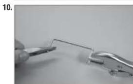
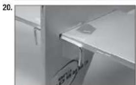
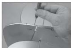
- Slide the stabilizer partially into the fuselage so the wood at the center is exposed. Mix 1/2 ounce (15ml) of 30-minute epoxy. Use an epoxy brush to apply the epoxy to the exposed wood on the top of the stabilizer.
- Carefully turn the model over and apply epoxy to the exposed wood on the bottom of the stabilizer. Slide the stabilizer back into position.
Use care not to get epoxy on the elevator joiner wire.
-
Once the alignment of the stabilizer has been verified, use a paper towel and isopropyl alcohol to remove any excess epoxy from the fuselage and stabilizer. Allow the epoxy to fully cure before proceeding.
If you find epoxy on the joiner wire, use the paper towel and isopropyl alcohol to clean the joiner. -
Use a pin vise and 1/16-inch (1.5mm) drill bit to drill a hole in the center of each hinge slot to allow the CA to wick into the hinge. Drill holes in both the elevators and stabilizer surfaces at this time. Place a T-pin in the center of each hinge along side the slot in the hinge. This will help center the hinge when it is placed in the elevators. Slide the hinges into position with the T-pin resting against the edge of the control surface.
- Fit the elevator into position on the stabilizer. Guide the joiner wire and hinges into position.
13.
14.
15
16
17
- Fit the elevator so the leading edge fits tightly against the trailing edge of the stabilizer.
- Check the fit of both elevators at this time. Once checked, remove the elevators.
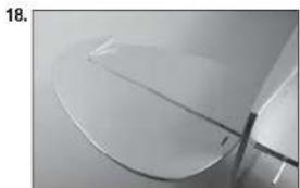
- Use a small strip of the clear packaging material and slide it between the joiner wire and stabilizer. Make sure the packing material is cut so it does not obstruct the hinge slot. Use a small piece of low-tack tape to hold the packing material in position.
The clear packing material is used to prevent accidentally gluing the elevators or joiner wire to the stabilizer.
- Mix a small amount of 15-minute epoxy. Use a toothpick to apply epoxy to the joiner wire.
- Use a toothpick to apply epoxy to the stabilizer where it contacts the joiner wire.
- Fit the elevators back into position. Remove the T-pins and slide the elevators tightly against the stabilizer. Use a paper towel and isopropyl alcohol to remove any excess epoxy before it begins to cure.
- Check the alignment of the elevators in relationship to the stabilizer at the tips. There should be enough gap between the balance tab and stabilizer to they can move freely.
Do not use CA accelerator when gluing hinges. The CA must be allowed to soak into each hinge to provide the greatest bond between the hinges and surrounding wood.
- Flex the elevator slightly, making sure to keep the gap between the elevator and stabilizer as narrow as possible. Saturate each of the hinges using thin CA. Apply CA to the top of the hinges.
- Flex the elevator slightly, making sure to keep the gap between the elevator and stabilizer as narrow as possible. Saturate each of the hinges using thin CA. Apply CA to the bottom of the hinges. Allow the CA to cure before proceeding.
- Gently pull on the flxed and moving surface to make sure the hinges are glued securely. If not, reapply thin CA to any hinges that are found loose.
- Flex the control surface through its range of motion a few times to break-in the hinges. This will reduce the initial load on the servo when the surface is fi rst actuated.
28.
TAIL WHEEL BRACKET INSTALLATION
- Position the steering tiller on the bottom of the rudder. The arms of the tiller will be perpendicular to the rudder centerline. Make sure the tiller is as far forward as possible, yet doesn't interfere with the operation of the rudder. Use a felt-tipped pen to mark the locations for the tiller mounting screws on the bottom of the rudder.
- Use a pin vise and 5/64-inch (2mm) drill bit to drill the two holes in the bottom of the rudder for the tiller mounting screws.
RUDDER INSTALLATION
- Use a pin vise and 1/16-inch (1.5mm) drill bit to drill a hole in the center of each hinge slot. This allows the CA to wick into the hinge. Drill holes in both the rudder and fin surfaces at this time. Place a T-pin in the center of the hinge. Slide the hinges into position with the T-pin resting against the edge of the control surface.
- Check the fit of the rudder to the fuselage. Make sure the tail wheel wire fits into the rudder, and that the notch fits over the tail wheel bushing. There should be no gap between the fin and rudder.
- Once the epoxy fully cures, apply thin CA to both sides of each hinge. Once the CA cures, gently pull on the fi xed surface and control surface to make sure the hinges are glued securely. If not, apply additional CA to secure each of the hinges.
1.
- Use a #2 Phillips screwdriver to thread an M3 x 10 self-tapping screw into each of the holes. Remove the screws, then apply a few drops of thin CA in each hole to harden the surrounding wood.
- Secure the tilter arm on the bottom of the rudder using two M3 x 10 self-tapping screws. Tighten the screws using a #2 Phillips screwdriver.
- Before installing the tail wheel bracket, thread an M3 x 12 socket head screw into each blind nut. If the screw does not thread in easily, use a 3mm tap to clean the threads in the blind nut.
1

2
3
4
5
- Place the tail gear bracing bracket in the notch in the fuselage. Use two M3 x 20 socket head caps screws to secure the tail wheel bracket. Apply a small amount of threadlock on each screw and use a 2.5mm hex wrench to tighten the screws. Use threadlock on all metal-to-metal fasteners to prevent them from vibrating loose.
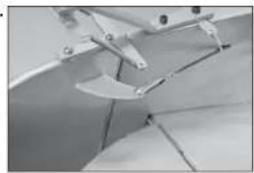
- Use side cutters to rim the excess wire from the springs. Use small pliers to bend the last coil to form a loop that can be connected to the tall wheel arm and tiller arm.
- Place the springs on the tiller arm and tail wheel steering arm. It may be necessary to adjust the springs slightly so the tail wheel aligns with the rudder.
TAIL WIRE BRACING INSTALLATION
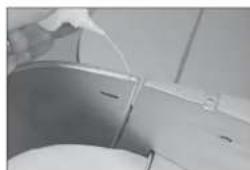
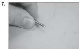
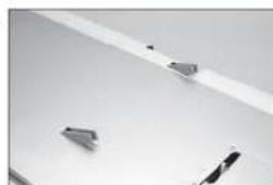
- Use piers to bend each of the fit fittings to about a 45-degree angle. Bias the bend toward the smaller hole in the fit fitting.
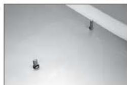
- Attach the fl fittings to the stabilizer using two M3 x 12 screws and two M3 nuts. Fitings are placed on the top and bottom of the stabilizer. Use threadlock on all the nuts to prevent them from vibrating loose.
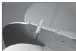
- Attach the fittings to the fin using an M3 x 12 screws and M3 nut. Fittings are placed on both sides of the rudder. Use threadlock on all the nuts to prevent them from vibrating loose.
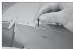
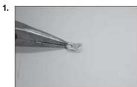
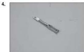
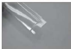
- Thread a cable end into the clevis. The threads of the cable end will protrude 1/8-inch (3mm) between the forks of the clevis. Prepare four of these connectors. Use threadlock on all metal-to-metal fasteners to prevent them from vibrating loose.
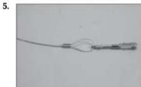
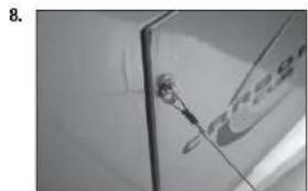
- Prepare one cable by sliding the cable through a sleeve, through the cable end, then back through the sleeve.
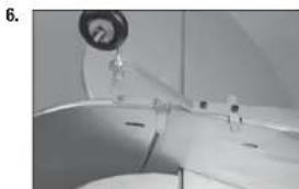
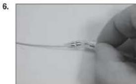
- Pull the excess cable light and use a crimping tool to complete the job. Repeat for all four of the ends.
- Attach the four connectors to the fittings on the top and bottom of the stabilizer.
- Repeat steps 5 and 6, only passing the cable through the fit fittings instead of the cable ends. The cables should have very light tension. Make sure the rudder and stabilizer are square as illustrated in the stabilizer installation section of this manual.
RUDDER AND ELEVATOR SERVO INSTALLATION
- Locate the rudder and elevator control horns. The taller control horn is used for the elevator, and the shorter horn for the rudder. Use sandpaper to scuff the bottom of the control horns. Use a paper towel and isopropyl alcohol to remove any oils or debris from the control horns.
- Check the fit of the elevator control horn. Make sure the horn does not protrude through the top, deforming the covering. If so, lightly sand the horn so it is flush on the top when installed. Use 5-minute epoxy to glue the elevator horn in position. Use the technique outlined earlier when installing the horns.
- Check the fit of the rudder control horn. Make sure the horn does not protrude through the opposite side, deforming the covering. If so, lightly sand the horn so it is flush on the opposite side when installed. Use 5-minute epoxy to glue the rudder horn in position. Use the technique outlined earlier when installing the horns.
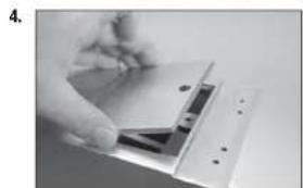
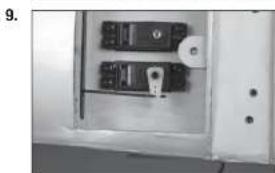
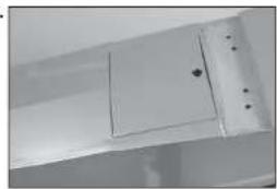
- Use a 2.5mm hex wrench to remove the screw from the servo hatch. Lift the hatch and set it aside.
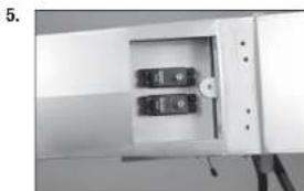
- Install the rudder and elevator servos in the fuselage with the servo outputs facing toward the front of the fuselage. Mark, drill and prepare the servo mounting holes as outlined earlier in this manual.
- Locate the 28-inch (711mm) elevator pushrod. Insert the pushrod through the front of the fuselage.
- Direct the pushrod through the fuselage toward the rear where the pushrod tubes are located.
- Guide the pushrod it into the elevator pushrod tube located slightly behind the servo compartment.
- Use the radio system to center the elevator servo. Prepare the servo arm by removing any arms that may interfere with the operation of the servo. Use a pin vise and 5/64-inch (2mm) drill bit to enlarge the hole in the arm that is 5/8-inch (16mm) from the center of the arm. Attach the z-bend of the pushrod to the servo arm, then attach the arm to the servo using the hardware provided with the servo.
-
Thread an M2 nut on the pushrod, then a metal clevis. With the servo centered, adjust the clevis so the elevator is centered when the clevis is attached to the elevator control horn. Once adjusted and connected, use pliers to tighten the nut against the clevis to prevent if from vibrating loose. Make sure to use threadlock on the nut so it won't vibrate loose.
-
Insert the 29-inch (736mm) rudder pushrod into the rudder pushrod tube following the same procedure as the elevator pushrod. Use the radio system to center the rudder servo. Prepare the servo arm by removing and arms that may interfere with the operation of the servo. Use a pin visse and 5/64-inch (2mm) drill bit to enlarge the hole in the arm that is 5/8-inch (16mm) from the center of the arm. Attach the z-bend of the pushrod to the servo arm, then attach the arm to the servo using the hardware provided with the servo.
- Thread an M2 nut on the pushrod, then a metal clevis. With the servo centered, adjust the clevis so the elevator is centered when the clevis is attached to the elevator control horn. Once adjusted and connected, use pliers to tighten the nut against the clevis to prevent if from vibrating loose. Make sure to use threadlock on the nut so it won't vibrate loose.
- Once the servos are connected to their respective control surfaces the hatch can be reinstalled covering the servos.
10.
11.
12.
13.

LANDING GEAR INSTALLATION
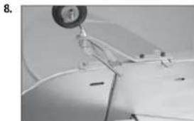
- Attach the mount for the landing gear using an M3 x 15 socket head cap screws and an M3 locknut. The mount for the main gear must be freely. Adjust as necessary. Attach all four brackets at this time. Use a 2.5mm hex wrench and 5.5mm nut driver to tighten the hardware.
- Repeat Step 1 to assemble both the left and right landing gear.
- Before installing the landing gear, thread an M3 x 12 socket head screw into each blind nut. If the screw does not thread in easily, use a 3mm tap to clean the threads in the blind nut.
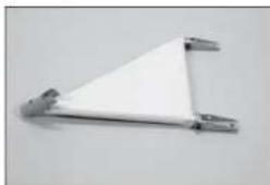
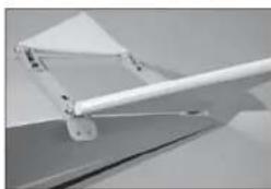
- Secure the main gear to the fuselage. The strut bracket fits between the fuselage and rear main gear mount and angles toward the top of the fuselage. Use two M3 x 12 socket head cap screws and a 2.5mm hex wrench to secure each bracket to the fuselage. Adjust the bracket as necessary so the landing gear can move freely. Use threadlock on all metal-to-metal fasteners to prevent them from vibrating loose.
- Attach the cross brace to the front main gear mounts using two M3 x 15 socket head cap screws and two M3 lock nuts. Use a 2.5mm hex wrench and 5.5mm nut driver to tighten the hardware.
1
2

3

4
5
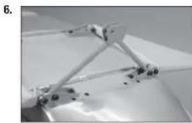
- Attach the strut assembly to the main gear and the cross brace. Use the two M3 x 12 socket head cap screws at the center, and the M3 x 15 socket head cap screws near the wheels. The screws are secured using M3 locknut, and tightened using a 2.5mm hex wrench and 5.5mm nut driver.
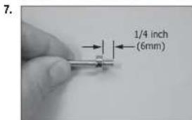
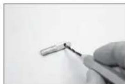
- Slide the M4 wheel collar to the axle. Secure the wheel collar 1/4 inch (6mm) from the end of the axle using the M3 setscrew and a 1.5mm hex wrench. Use threadlock on all metal-to-metal fasteners to prevent them from vibrating loose.
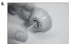
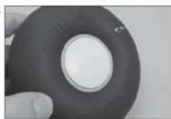
- Apply a drop of light machine oil to the axle. Slide the outer end of the axle into the wheel hub. Fit the hube into the wheel.
- Fit a second wheel hub into the wheel over the axle.
- Assemble the wheel by inserting the four M3 x 25 machine screws through the hub from the outside of the wheel.
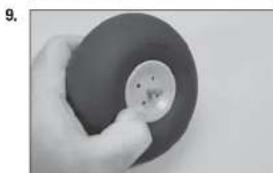
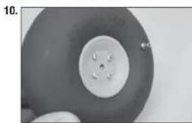
- Use four M3 nuts to secure the wheel hubs together. Make sure the wheel can rotate freely on the axle. Use a #2 Phillips screwdriver and 5.5mm nut driver to tighten the hardware. Use threadlock on all metal-to-metal fasteners to prevent them from vibrating loose.
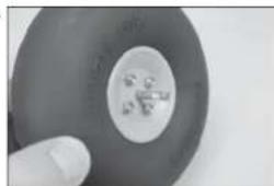
- Attach the hub cap to the wheel using a small amount of silicone adhesive.
- Slide the axle into the main gear. Secure it using the M4 x 6 setscrew, tightening the setscrew on the fl at of the axle. Use a 2mm hex wrench and threadlock when installing the setscrew. Use threadlock on all metal-to-metal fasteners to prevent them from vibrating loose.
MOTOR AND BATTERY INSTALLATION
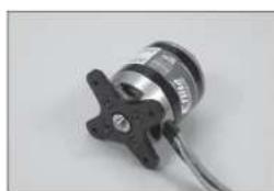
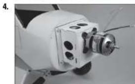
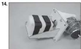
- Use a #2 Phillips screwdriver and threadlock to attach the X-mount to the motor. Use threadlock on all metal-to-metal fasteners to prevent them from vibrating loose.
- Insert the screws included with the motor through the holes of the X-mount and into the holes on the motor box.
11.
12

13
1.
2.
-
Thread the blind nuts included with the motor onto the screws with the prongs facing toward the wood. Apply threadlock to the screws and tighten them using a 2.5mm hex wrench.
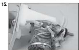
-
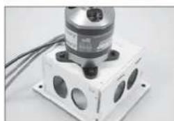
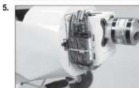
Attach the motor box to the fuselage using four M4 x 20 socket head cap screws and four M4 washers. Apply threadlock to the screws before tightening them using a #2 Phillips screwdriver.
Secure a 12-inch (300mm) servo extension to connect the speed control to the receiver.
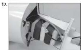
- The speed control is attached to the side of the motor box using hook and loop tape (not included) and tie wraps (not included). Secure the switch so it does not interfere with the operation of the model.
It may be necessary to change the connectors on the speed control to match the battery.
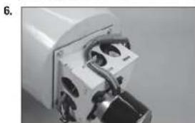
- Secure the wiring so it won't interfere with the operation of the motor or the installation of the battery.
Secure a 6-inch (150mm) EC3 extension to connect the speed control to the battery.
It may be necessary to change the connectors on the motor to match the speed control.
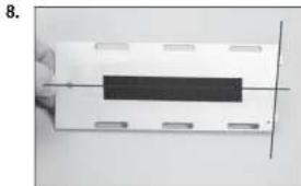
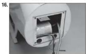
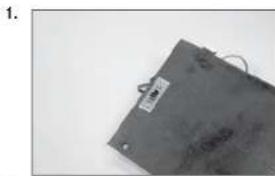
- Place hook and loop tape on the battery to keep the battery from sliding inside the fuselage.
Do not cover safety warnings on the battery with hook and loop tape.
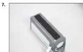
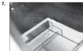
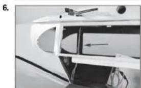
- Place hook and loop tape on the battery tray to keep the battery from sliding inside the fuselage. The front of the battery tray is angled to match the thrust built into the fi rewall. Make sure to apply the hook and loop tape to the top of the tray.
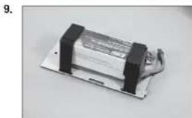
- Secure the battery to the battery tray using hook and loop straps. The position of the battery can be adjusted to achieve the correct balance point for your model.
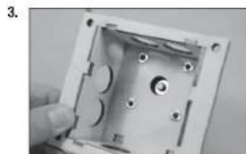
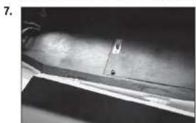
- Fit the battery tray into the fuselage. The tabs at the front of the tray will fit into notches in the back of the fi rewall. Secure the battery tray using an M3 x 12 socket head cap screw and M3 washer. Tighten the screw using a 2.5mm hex wrench.
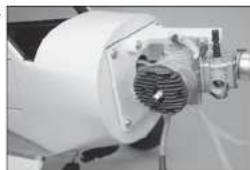
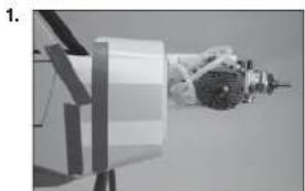
GAS ENGINE INSTALLATION
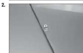
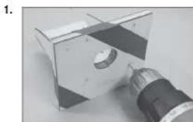
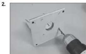
- Use tape to secure the template to the fi rewall. Use a drill and 1/16-inch (1.5mm) drill bit to drill the pilot holes for the engine mount into the fi rewall.
- Remove the template from the fi rewall. Use a 3/16-Inch (4.5mm) drill bit to enlarge the pilot holes in the fi rewall.
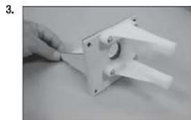
- Insert the four M4 x 20 machine screws through the holes in the mount and into the holes drilled in the previous step.
- Place the four M4 washers on the screws, then thread the M4 locknuts onto the screws. Use a 7mm nut driver and #2 Phillips screwdriver to tighten the screws.
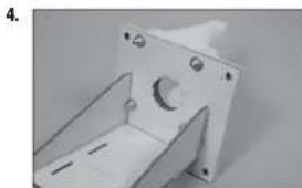
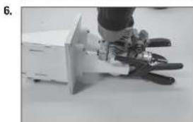
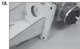
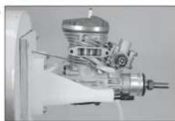
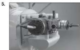
- Position the engine between the engine mounting rails. Adjust the engine so the distance between the face of the fll rewall and face of the drive washer is 53/8 inches (137mm). Use clamps to hold the engine securely to the engine mounting rails.
- Mark the position of the rear engine mounting bolts using an 11/64-inch (4.5mm) drill bit. Remove the engine from the rails, then drill the holes for the engine mounting bolts.
We recommend removing the mounts from the fuselage and using a drill press to drill the holes, so they are aligned square to the mounting rails.
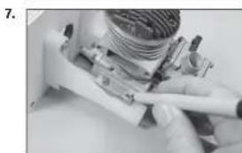
- Place the engine back between the rails and insert either 6-32 x 11/4-inch machine screws (not included) or M4 x 30 machine screws (not included) through the rear mounting holes and the mounting rails to position the engine. Use a felt-tipped pen to mark the location for the front mounting holes. Drill the holes are outline in the previous step.
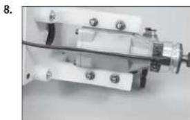
- Secure the engine to the mounting rails. Use four M4 x 30 machine screws, eight M4 washers and four M4 locknuts.
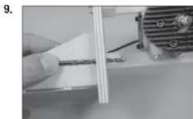
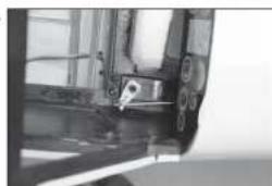
- Use a drill and 5/32-inch (4mm) drill bit to drill the holes for the throttle pushrod.
- Locate the hole outside the tank tray, and directly above the lower engine mounting rail.
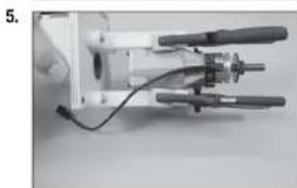
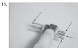
- Prepare the stopper assembly by placing a small amount of solder on the end of the tubes shown. This will help keep the fuel lines secure when installed. Use care not to overheat the tubing, which could melt the stopper material.
- Secure the tubing to the clunk and tube from the stopper using thin wire. This will keep the tubing from sliding loose inside the tank.
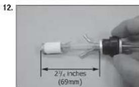
- Secure three 140mm pieces of fuel tubing to the tubes of the stopper. Note the position of each tube so they can be connected when the tank is installed in the fuselage.
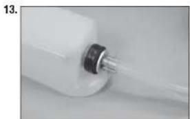
- Position the fuel tank on the tray, guiding the fuel tubes through the opening in the fi rewall. Use the hook and loop straps to secure the fuel tank to the fuel tank tray.
- Connect the fuel line from the clunk to the carburetor. Make sure to install the fuel fiiter included with your engine, securing the tubing to each fi tting using tie wraps or wire ties.
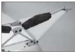
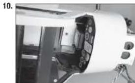
- Wrap the ignition module using 1/2-inch (13mm) foam rubber. This will keep it from moving inside the fuselage when the engine has been installed. Place the module in the fuselage. Guide the wires to the receiver into the fuselage, and the spark plug and sensor leads forward out of the fuselage.
- Position the engine assembly near the fuselage. The sensor lead and spark plug wire will fit through the opening in the fl rewall. Connect and secure the sensor lead.
- Carefully fit the engine assembly into the fuselage. Guide the leads through the fi rewall, and keep the ignition module above the fuel tank. Once positioned, secure the engine assembly to the fuselage using four M4 x 30 machine screws and four M4 washers. Make sure to use threadlock on all the screws to prevent them from vibrating loose.
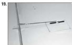
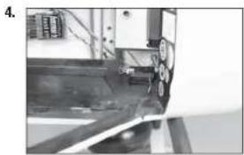
- Thread a clevis on the throttle pushrod. Guide the pushrod through the hole in the fi rewall made earlier. Bend the pushrod as necessary to it lines up with the hole, and will clear the muffe when it is installed later in this manual.
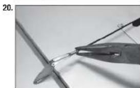
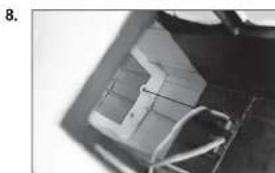
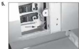
- Mount the throttle servo in the fuselage. Position the servo as close to the fuel tank as possible with the servo output facing the rear of the fuselage.
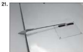
- Use a pushrod connector (not included) to connect the throttle linkage to the servo. Use side cutters to remove any excess wire that may interfere with the operation of the servo. Check that the carburetor moves from fully open to fully closed using the radio system.
18.
19.

20
21.
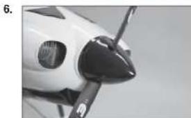
COWLING AND SPINNER INSTALLATION
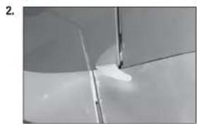
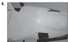
- Cut four pieces of paper 1/2 inch (12mm) wide. Tape the paper to the sides of the fuselage to indicate the location of the sub-fi rewall.
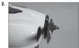
- Slide the cowling on the fuselage, making sure the paper markers are on the outside of the cowl. With the spinner backplate and propeller attached to the motor shaft, position the cowl so there is a 3/32-inch (2mm) gap between the backplate and cowl. Also make sure the cowl is aligned with the backplate and trim scheme. Use low-tack tape to keep the cowl attached to the fuselage for the following steps.
- Use a pin vise and 1/16-inch (1.5mm) drill bit to drill four holes in the cowl using the paper templates as a guide. Make sure to drill into the 1/4-inch (6mm) wide sub-fi rewall.
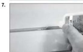
- Remove the propeller and cowling from the fuselage. Thread a cowl mounting screw into each of the holes. Remove the screws, then apply a small amount of thin CA to harden the threads made in the mounting blocks. Place the cowl back on the fuselage and secure it using the screws listed. Use a #1 Phillips screwdriver to tighten the screws.
Important Information About Your Propeller
Always ensure the propeller is balanced before installing it onto the shaft. An unbalanced propeller may cause poor flight characteristics.
If it is necessary to enlarge the hole in the propeller, make sure to check the balance of the propeller afterwards.
- Attach the muffler to the engine and connect any items from the ignition module to their locations on the engine.
- Attach the spinner to the motor. Make sure the spinner cutouts do not contact the propeller blades.
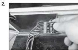
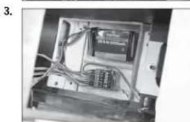
RECEIVER AND RECEIVER BATTERY INSTALLATION
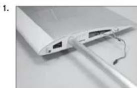
- Use a hobby knife with a #11 blade to remove the material from the aft edge of the receiver and battery cover. Drill two holes for the switch mounting screws using a 5/64-inch (2mm) drill bit. Mount the switch to the cover using the hardware included with the switch.
Use the switch plate as a template when preparing the cover for the switch. - Connect the rudder and elevator servo leads to the receiver. Connect an 18-inch (460mm) lead for the flaps and allerons to the receiver.
Longer 24-inch (600mm) leads can be used for the allerons and flaps and then routed underneath the cockpit floor for a clean installation of the radio system. - Mount the receiver and receiver battery in the fuselage using hook and loop tape (not included). Route the servo leads neatly underneath the radio tray.
- Secure the remote receiver inside the fuselage using hook and loop tape (not included). Make sure to orient the antenna on the remote receiver at a different angle than that of the main receiver for the best operation of your radio system.
OPTIONAL 24-INCH FLAP AND AILERON SERVO LEAD INSTALLATION
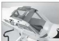
- Holes can be made in the floor of the servo tray using a hobby knife and #11 blade to route 24-inch (600mm) alleron and flap servo leads underneath the cockpit floor and up the inside of the formers.
- Use small tie wraps to secure the leads to the inside edges of the formers so the windows can be installed in the next section of the manual.
- Secure the receiver cover inside the fuselage using an M3 x 12 socket head cap screw and M3 washer. When using the shorter fl ap and aileron extensions, a notch will need to be made in the cover to route the leads from the receiver to plug into the leads from the wing.
- WINDOW INSTALLATION
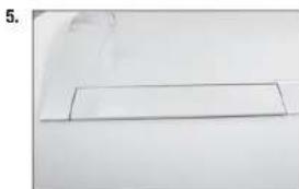
- Use a hobby knife to trim the bottom of the windows that fit into the door. Trim the bottom so there is 1/16-inch (1mm) of material below the edge of the fl at area below the window. The fl at area is where the window will contact the door frame, allowing you to glue it into position.
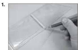
- Use canopy glue to glue the side and rear windows to the inside of the fuselage. Use tape to hold the windows in position until the glue has fully cured.
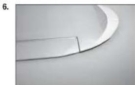
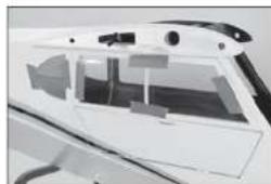
- Fit the front/top window into position. The top window folds over the fuselage. Use canopy glue and low-tack tape to glue the windows into position.
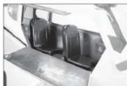
You can add scale details to the interior of your model before gluing the windows in position. There are numerous avenues for finding additional information as a guide to increase the scale appearance of your model available. - Use 15-minute epoxy to glue the seats inside the fuselage. Use scale references to correctly position the seats.
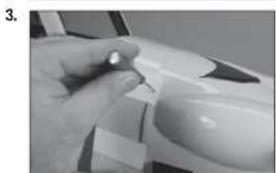
If flying your model using an electric power system, use hook and loop tape to secure the front seat so it can be easily removed to change the motor battery. - Use hobby scissors to carefully trim the ends from the landing light lenses. Leave plenty of material so they can be glued to the wing surface.
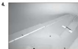
- Trim the lenses as necessary so they fit to the contour of the wing. Use canopy glue to glue the lenses into position. A small amount of low-tack tape is used to hold the lenses in position until the glue fully cures.
2
3
4.
5
6


WING STRUT INSTALLATION
- Before installing the strut brackets, thread an M3 x 12 socket head screw into each blind nut. If the screw does not thread in easily, use a 3mm tap to clean the threads in the blind nut.
- Attach the strut bracket to the bottom the wing using two M3 x 12 socket head cap screws for each bracket. Make sure to use threadlock on each of the screws to prevent them from vibrating loose.
- Use a pin vise and 1/8-inch (3 mm) drill bit to remove any excess paint from the hole in the jury strut mounts.
- Thread the jury strut mounts into the holes in the wing. The upper lip of the mount will be fl ush with the bottom of the wing.
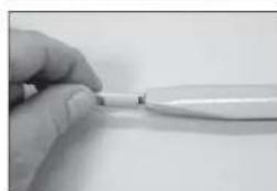
- Thread the ends on the struts so there is roughly 1/8 inch (3mm) of thread exposed between the end of the strut and the flting. The exact position of the end will be adjusted when the struts are installed.

1.
2.
3.
4.
5.
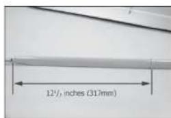
- Measure the distance between the end of the strut and the jury strut mount. The mounts are not centered on the strut: the side where the bracket is positioned 12^ / 2 inches (317mm) from the end of the strut will be the side that attaches to the bracket.
- Attach the struts to the brackets using M3 x 12 socket head cap screws and M3 locknuts.
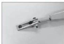
- Attach the jury struts to the jury strut mount using M3 x 12 socket head cap screws and M3 locknuts. Attach the spreader bar to the front and rear struts using M3 x 15 socket head cap screws and M3 locknuts. The strut bracket and spreader bar are inside the jury strut.
- Check the positioning of the jury struts and hardware using the photos 9 and 10.
- Use a square to check that the jury struts are perpendicular to the bottom of the wing. If not, the jury strut mounts on the struts can be repositioned to adjust the jury struts.
6
7

8

9

10
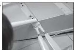
-
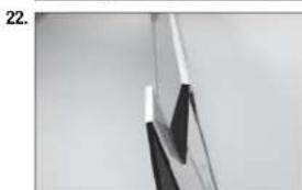
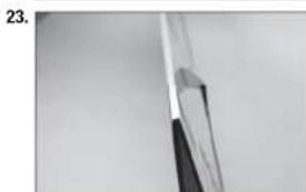
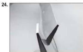
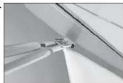
Position the wing back on the fuselage as outlined earlier in this manual. Adjust the ends on the struts so the holes in the ends line up with the holes in the strut mounting tab. Slide the pin through the end and tab, then fit a silicone tube on the pin. The pins are secured using the clips as shown in the photo.
-
Check the positioning of the pins and clips as shown in photos 12 and 13.
Use a hobby knife to trim the silicone tube into 1/8-inch (3mm) thick pieces so the clips are easier to install.
11.
12

DECAL INSTALLATION
- Apply the decals to your model using the photos located in this section of the manual and the box art from your model. Use a spray bottle and a drop of dish washing liquid or glass cleaner sprayed in the location of the decal to allow repositioning of the decal. Use a paper towel as a squeegee to remove excess water from under the decal. Allow the model to rest overnight so the remaining water can evaporate.

CENTER OF GRAVITY
An important part of preparing the aircraft for flight is properly balancing the model.
- Attach the wing panels to the fuselage. Make sure to connect the leads from the aleron to the appropriate leads from the receiver. Make sure the leads are not exposed outside the fuselage before tightening the wing bolts. Your model should be light-ready before balancing.
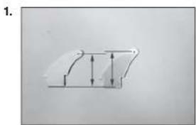
- The recommended Center of Gravity (CG) location for your model is 3 15 - 4% inches (100-120mm) back from the leading edge at the center of the wing.
- When balancing your model, make sure it is assembled and ready for flight. Support the plane upright at the marks made on the wing with your fingers or a commercially available balancing stand. This is the correct balance point for your model.
CAUTION:
You must adjust your aircraft's center of
gravity and balance your model properly before attempting flights.
CONTROL THROWS
- Turn on the transmitter and receiver of your model. Check the movement of the rudder using the transmitter. When the stick is moved to the right, the rudder should also move right. Reverse the direction of the servo at the transmitter if necessary.
- Check the movement of the elevator with the radio system. Moving the elevator stick toward the bottom of the transmitter will make the airplane elevator move up.
- Check the movement of the allerons with the radio system. Moving the alleron stick to the right will make the right alleron move up and the left alleron move down.
- Use a throw meter to adjust the throw of the elevator, allerons and rudder.
Aileron (high rate), 30% Exponential: Aileron (low rate), 20% Exponential:
Up: 7/8 inches (22mm) Up: 1/2 inches (13mm)
Down: 11/16 inches (18mm) Down: 7/16 inches (11mm)
Elevator (high rate), 30% Exponential: Elevator (low rate), 20% Exponential:
Up: 1y15 inches (30mm) Up: 25/32 inches (20mm)
Down: 1 inch (25mm) Down: 19/32 inches (15mm)
Rudder (high rate), 30% Exponential:
Right: 25/42 Inches (55mm) Right: 1
Left: 2% inches (55mm) Left: 1
Rudder (low rate), 20% Exponential:
^al_32 Inches (33mm)
% inches (33mm)
Flaps:
Mid 7/8 inches (22mm)
Landing Adjust the maximum throw without binding the servo or linkage.
These are general guidelines measured from our own flight tests. You can experiment with different rates to match your preferred style of flying.
Travel Adjust and Sub-Trims are not listed and should be adjusted according to each individual model and preference. Always install the control horns 90 degrees to the servo center line. Use sub-trim as a last resort to center the servos.
We highly recommend re-binding the radio system once all of the control throws are set. This will keep the servos from moving to their endpoints until the transmitter and receiver connect.
□ BUILDING NOTES:
PREFLIGHT CHECKLIST
- Charge the transmitter, receiver and motor battery for your airplane. Use the recommended charger supplied with your radio system. Follow the instructions provided with the radio. Charge the radio system the night before each flight session. Charge the transmitter and receiver batteries using only included or manufacturer-recommended chargers. Follow all manufacturer's instructions for your electronic components.
- Check the radio installation and make sure all control surfaces (allerton, elevator, rudder and throttle) move correctly (i.e., the correct direction and with the recommended throws).
- Check all the hardware (control horns, servo horns, and clevises) to make sure they are secure and in good condition.
- Prior to each lying session (and especially with a new model), perform a range check of your radio system. See your radio manual for the recommended range and instructions for your particular radio system.
Run the motor. With the model securely anchored, repeat the range check procedure. The range should not be signifi cantly affected. If it is, do not attempt to fi! Remove the radio equipment and have it inspected by the manufacturer.
DAILYFLIGHTCHECKS
- Check the battery voltage of the transmitter battery. Do not fit below the manufacturer's recommended voltage. To do so can crash your aircraft.
When you check these batteries, ensure you have the polarities correct on your expanded scale voltmeter. - Check all hardware (linkages, screws, nuts, and bolts) prior to each day's flight. Ensure that binding does not occur and that all parts are properly secured.
- Ensure all surfaces are moving in the proper manner.
- Perform a ground range check before each day's flying session.
- Prior to starting your aircraft, turn off your transmitter, then turn it back on. Do this each time you start your aircraft. If any critical switches are on without your knowledge, the transmitter alarm will sound a warning.
- Check that all trim levers are in the proper location.
- All servo pigtails and switch harness plugs should be secured in the receiver. Make sure the switch harness moves freely in both directions.
LIMITED WARRANTY
What this Warranty Covers
Horizon Hobby, LLC, (Horizon) warrants to the original purchaser that the product purchased (the "Product") will be free from defects in materials and workmanship at the date of purchase.
What Is Not Covered
This warranty is not transferable and does not cover (i) cosmetic damage, (ii) damage due to acts of God, accident, misuse, abuse, negligence, commercial use, or due to improper use, installation, operation or maintenance, (iii) modification of or to any part of the Product, (iv) attempted service by anyone other than a Horizon Hobby authorized service center, (v) Product not purchased from an authorized Horizon dealer, (vi) Product not compliant with applicable technical regulations, or (vii) use that violates any applicable laws, rules, or regulations.
OTHER THAN THE EXPRESS WARRANTY ABOVE, HORIZON MAKES NO OTHER WARRANTY OR REPRESENTATION, AND HEREBY DISCLAIMS ANY AND ALL IMPLIED WARRANTYES, INCLUDING, WITHOUT LIMITATION, THE IMPLIED WARRANTY OF NON-INFRINGEMENT, MERCHANTABILITY AND FITNESS FOR A PARTICULAR PURPOSE. THE PURCHASER ACKNOWLEDGES THAT THEY ALONE HAVE DETERMINED THAT THE PRODUCT WILL SUITABLY MEET THE REQUIREMENTS OF THE PURCHASER'S INTENDED USE.
Purchaser's Remedy
Horizon's sole obligation and purchaser's sole and exclusive remedy shall be that Horizon will, at its option, either (i) service, or (ii) replace, any Product determined by Horizon to be defective. Horizon reserves the right to inspect any and all Product(s) involved in a warranty claim. Service or replacement decisions are at the sole discretion of Horizon. Proof of purchase is required for all warranty claims. SERVICE OR REPLACEMENT AS PROVIDED UNDER THIS WARRANTY IS THE PURCHASER'S SOLE AND EXCLUSIVE REMEDY.
Limitation of Liability
HORIZON SHALL NOT BE LIABLE FOR SPECIAL, INDIRECT, INCIDENTAL OR CONSEQUENTIAL DAMAGES, LOSS OF PROFITS OR PRODUCTION OR COMMERCIAL LOSS IN ANY WAY, REGARDLESS OF WHETHER SUCH CLAIM IS BASED IN CONTRACT, WARRANTY, TORT, NEGLIGENCE, STRICT LIABILITY OR ANY OTHER THEORY OF LIABILITY, EVEN IF HORIZON HAS BEEN ADVISED OF THE POSSIBILITY OF SUCH DAMAGES. Further, in no event shall the liability of Horizon exceed the individual price of the Product on which liability is asserted. As Horizon has no control over use, setup, fi nal assembly, modifcation or misuse, no liability shall be assumed nor accepted for any resulting damage or injury. By the act of use, setup or assembly, the user accepts all resulting liability. If you as the purchaser or user are not prepared to accept the liability associated with the use of the Product, purchaser is advised to return the Product immediately in new and unused condition to the place of purchase.
Law
These terms are governed by Illinois law (without regard to conflict of law principals). This warranty gives you specific legal rights, and you may also have other rights which vary from state to state. Horizon reserves the right to change or modify this warranty at any time without notice.
WARRANTY SERVICES
Questions, Assistance, and Services
Your local hobby store and/or place of purchase cannot provide warranty support or service. Once assembly, setup or use of the Product has been started, you must contact your local distributor or Horizon directly. This will enable Horizon to better answer your questions and service you in the event that you may need any assistance. For questions or assistance, please visit our website at www.horizonhobby.com, submit a Product Support Inquiry, or call the toll free telephone number referenced in the Warranty and Service Contact Information section to speak with a Product Support representative.
Inspection or Services
If this Product needs to be inspected or serviced and is compliant in the country you live and use the Product in, please use the Horizon Online Service Request submission process found on our website or call Horizon to obtain a Return Merchandise Authorization (RMA) number. Pack the Product securely using a shipping carton. Please note that original boxes may be included, but are not designed to withstand the rigors of shipping without additional protection. Ship via a carrier that provides tracking and insurance for lost or damaged parcels, as Horizon is not responsible for merchandise until it arrives and is accepted at our facility. An Online Service Request is available at http://www.horizonhobby.com/content/ service-center render-service-center. If you do not have internet access, please contact Horizon Product Support to obtain a RMA number along with instructions for submitting your product for service. When calling Horizon, you will be asked to provide your complete name, street address, email address and phone number where you can be reached during business hours. When sending product into Horizon, please Include your RMA number, a list of the Included items, and a brief summary of the problem. A copy of your original sales receipt must be included for warranty consideration. Be sure your name, address, and RMA number are clearly written on the outside of the shipping carton.
NOTICE: Do not ship LiPo batteries to Horizon. If you have any issue with a LiPo battery, please contact the appropriate Horizon Product Support office.
Warranty Requirements
For Warranty consideration, you must include your original sales receipt verifying the proof-of-purchase date. Provided warranty conditions have been met, your Product will be serviced or replaced free of charge. Service or replacement decisions are at the sole discretion of Horizon.
Non-Warranty Service
Should your service not be covered by warranty, service will be completed and payment will be required without notification or estimate of the expense unless the expense exceeds 50% of the retail purchase cost. By submitting the item for service you are agreeing to payment of the service without notification. Service estimates are available upon request. You must include this request with your item submitted for service. Nonwarranty service estimates will be billed a minimum of 12 hour of labor. In addition you will be billed for return freight. Horizon accepts money orders and cashier's checks, as well as Visa, MasterCard, American Express, and Discover cards. By submitting any item to Horizon for service, you are agreeing to Horizon's Terms and Conditions found on our website http://www.horizonhobby.com/content/service-center_render-service-center.
ATTENTION: Horizon service is limited to Product compliant in the country of use and ownership. If received, a non-compliant Product will not be serviced. Further, the sender will be responsible for arranging return shipment of the un-serviced Product, through a carrier of the sender's choice and at the sender's expense. Horizon will hold non-compliant Product for a period of 60 days from notification, after which it will be discarded.
1075

WARRANTY AND SERVICE CONTACT INFORMATION
| Country of Purchase | Horizon Hobby Contact Information Address | ||
| United States of America | Horizon Service Center (Repairs and Repair Requests) | servicecenter.horizonhobby.com/RequestForm/ | 4105 Fieldstone RdChampaign, Illinois,61822 USA |
| Horizon Product Support (Product Technical Assistance) | productsupport@horizonhobby.com | ||
| 877-504-0233 | |||
| Sales | websales@horizonhobby.com800-338-4639 | ||
| United Kingdom | Service/Parts/Sales:Horizon Hobby Limited | sales@horizonhobby.co.uk Units+44 (0) 1279 641 097 | 1-4, Ployters Rd,Staple TyHarlow, Essex, CM18 7NS,United Kingdom |
| Germany | Horizon Technischer Service | service@horizonhobby.de Christian-Junge-Straße 125337 Elmshorn,Germany | |
| Sales: Horizon Hobby GmbH +49 (0) 4121 2655 100 | |||
| France | Service/Parts/Sales:Horizon Hobby SAS | infofrance@horizonhobby.com+33 (0) 1 60 18 34 90 | 11 Rue Georges Charpak77127 Lieusaint, France |

INSTRUCTIONS FOR DISPOSAL OF WEEE BY USERS IN THE EUROPEAN UNION

This product must not be disposed of with other waste. Instead, it is the user's responsibility to dispose of their waste equipment by handing it over to a designated collections point for the recycling of waste electrical and electronic equipment. The separate collection and recycling of your waste equipment at the time of disposal will help to conserve natural resources and ensure that it is recycled in a manner that protects human health and the environment. For more information about where you can drop off your waste equipment for recycling, please contact your local city office, your household waste disposal service or where you purchased the product.

FAA INFORMATION
Prior to flying, contact your local or regional modeling organizations for guidance and familiarize yourself with the current local rules and FAA regulations governing model aviation in your location.
More information about model aviation can be found at www.modelaircraft.org. The Federal Aviation Administration can be found online at www.faa.gov.
You are required to register with the FAA if you own this product. For up-to-date information on how to register with the FAA, please visit https://registermyuas.faa.gov/ For additional assistance on regulations and guidance on UAS usage, visit knowbeforeyoufly.org/

HÄngen VON QUERRUDERN UND KLAPPEN
Runter: 25mm Runter: 15mm
30% Exponential 20% Exponential
Rechts: 55mm Rechts: 33mm
Links: 55mm Links: 33mm
Klappen:
Mite: 22mm
NOTES RELATIVES AU MONTAGE:
CHECKLIST D'AVANT VOL

© 2016 Horizon Hobby, LLC.
Hangar 9, DSMX, EC3 and the Horizon Hobby logo are trademarks or registered trademarks of Horizon Hobby, LLC. The Spektrum trademark is used with permission of Bachmann Industries, Inc.
Cub Crafters, Carbon Cub, associated emblems and logos, and body designs of vehicles are either registered trademarks or trademarks of Cub Crafters, Inc. and are used with permission.
All other trademarks, service marks and logos are the property of their respective owners. Patents pending.
42977.2 Created 10/2015