
75V12H870001 - Video projector EPSON - Free user manual and instructions
Find the device manual for free 75V12H870001 EPSON in PDF.
| Product type | Projector mount adapter |
| Brand | Epson |
| Model | 75V12H870001 |
| Projector compatibility | Epson PowerLite 420/430/520/530/425W/435W/525W/535W/570/580/585W |
| SMART Board compatibility | SMART Board series i3, i4, i5 (models UF55/55W/65/65W/70/70W/75/75W) |
| Plate dimensions | 8.83 x 11.53 inches (224 x 293 mm) |
| Maximum supported weight | 5.9 kg (13 lb) |
| Included hardware | M4 x 16 mm screws (x4), 1/4-20 x 1/2 in screws (x1), washers (x4), 5/32 in security wrench, interface bracket (J) |
| Intended use | Replacement for existing SMART mounts for mounting Epson projector on lift arm |
| Installation | Requires basic tools (screwdriver, wrench) - follow step-by-step instructions |
| Safety instructions | Do not exceed max weight, do not use outdoors, do not use if damaged, ensure structure is sturdy |
| Maintenance | Clean with a soft dry cloth. Do not use solvents. |
| Replacement parts | Contact the manufacturer (Milestone AV Technologies) for replacement parts |
| Repairability | Do not attempt to repair yourself. Return to an authorized service center. |
| Manufacturer | Milestone AV Technologies |
| Distributor | Epson America, Inc. |
| Part number | V12H870001 |
| Warranty | See Epson warranty terms |
| Country of origin | Not specified (likely China) |
| Standards | Compliant with MILESTONE safety guidelines |
Frequently Asked Questions - 75V12H870001 EPSON
User questions about 75V12H870001 EPSON
0 question about this device. Answer the ones you know or ask your own.
Ask a new question about this device
Download the instructions for your Video projector in PDF format for free! Find your manual 75V12H870001 - EPSON and take your electronic device back in hand. On this page are published all the documents necessary for the use of your device. 75V12H870001 by EPSON.
USER MANUAL 75V12H870001 EPSON
INSTALLATION INSTRUCTIONS
natural_image
Isometric technical drawing of a mechanical component with labeled points (no text or symbols beyond basic markings)Adapter for SMART UF55/65/70/75 Series Mounts
Milestone AV Technologies and its affiliated corporations and subsidiaries (collectively "Milestone"), intend to make this manual accurate and complete. However, Milestone makes no claim that the information contained herein covers all details, conditions or variations, nor does it provide for every possible contingency in connection with the installation or use of this product. The information contained in this document is subject to change without notice or obligation of any kind. Milestone makes no representation of warranty, expressed or implied, regarding the information contained herein. Milestone assumes no responsibility for accuracy, completeness or sufficiency of the information contained in this document.
SMART Board® is a registered trademark of SMART Technologies.
Epson® is a registered trademark of Seiko Epson Corporation.
PowerLite® is a registered trademark of Seiko Epson Corporation.

IMPORTANT SAFETY INSTRUCTIONS

WARNING: A WARNING alerts you to the possibility of serious injury or death if you do not follow the instructions.

CAUTION: A CAUTION alerts you to the possibility of damage or destruction of equipment if you do not follow the corresponding instructions.

WARNING: Failure to read, thoroughly understand, and follow all instructions can result in serious personal injury, damage to equipment, or voiding of factory warranty! It is the installer's responsibility to make sure all components are properly assembled and installed using the instructions provided.

WARNING: Failure to provide adequate structural strength for this component can result in serious personal injury or damage to equipment! It is the installer's responsibility to verify the structure to which the existing SMART projector mount is attached can support five times the combined weight of all equipment. In addition, the installer is responsible to verify the existing SMART projector mount was installed according to the manufacturer's requirements and is undamaged.

WARNING: Exceeding the weight capacity can result in serious personal injury or damage to equipment! It is the installer's responsibility to make sure the weight of the projector attached to the V12H870001 does not exceed 13 lbs (5.9 kg).

WARNING: Use this mounting system only for its intended use as described in these instructions. Do not use attachments not recommended by the manufacturer.

WARNING: Never operate this mounting system if it is damaged. Return the mounting system to a service center for examination and repair.

WARNING: Do not use this product outdoors.
IMPORTANT ! : The V12H870001 brackets are designed to be attached ONLY to the Epson® projectors (listed in Table 1, Table 2, and Table 3) which are replacing existing SMART UF55, UF55W, UF65, UF65W, UF70, UF70W, UF75, and UF75W projectors used ONLY with SMART Board® Models as listed in Table 1, Table 2, and Table 3.
--SAVE THESE INSTRUCTIONS--
DIMENSIONS

text_image
DIMENSIONS: INCHES 8.83 11.53 8709-000001 PRODUCT LABEL A B A B A 1 1 1 1
text_image
8.83 11.53 DIMENSIONS: INCHESTOOLS REQUIRED FOR INSTALLATION

text_image
15/28 5/32"- security (included) M2.5 (included)PARTS
text_image
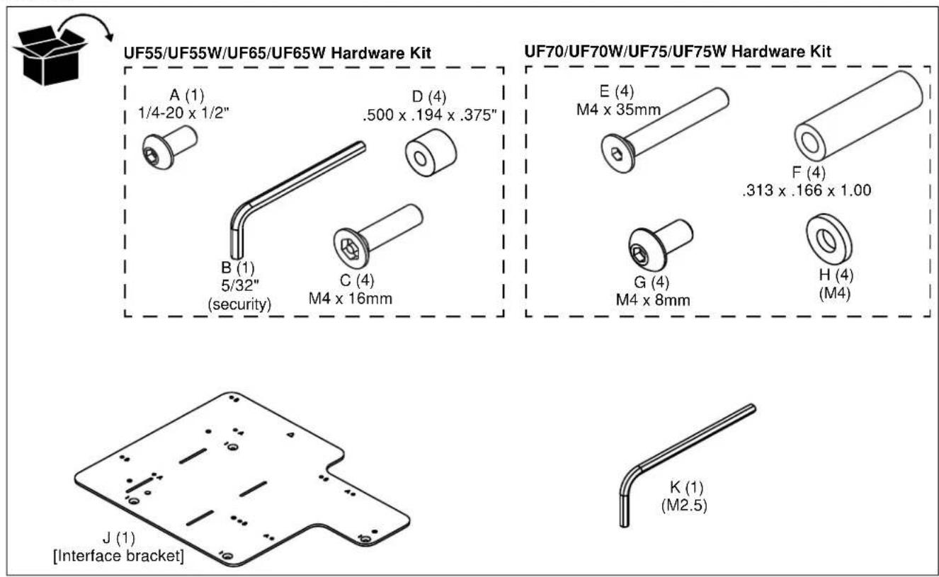
UF55/UF55W/UF65/UF65W Hardware Kit A (1) 1/4-20 x 1/2" D (4) .500 x .194 x .375" B (1) 5/32" (security) C (4) M4 x 16mm UF70/UF70W/UF75/UF75W Hardware Kit E (4) M4 x 35mm F (4) .313 x .166 x 1.00 G (4) M4 x 8mm H (4) (M4) J (1) [Interface bracket] K (1) (M2.5)INSTALLATION

WARNING: OVER TIGHTENING OF SCREWS CAN DAMAGE PARTS AND MAY LEAD TO SERIOUS PERSONAL INJURY AND DAMAGE TO EQUIPMENT! DO NOT over tighten screws when installing interface bracket.
IMPORTANT ! : Line up the triangle on the interface bracket (J) with the center of the projector lens to match up with the correct mounting hole pattern. The interface bracket (J) may be flipped over to accommodate all required mounting hole patterns.
IMPORTANT ! : Proceed to Replacing SMART i3 & i4 Systems, Replacing SMART i5 Systems (UF75/UF75W), or Replacing SMART i5 Systems (UF70/UF70W) section to complete installation of V12H870001.
Replacing SMART i3 & i4 Systems (UF55/UF55W/UF65/UF65W Projectors)
Table 1: Replacing SMART i3 & i4 Systems (UF55/UF55W/UF65/UF65W Projectors)
| SMART Board Models (i3 & i4 Series) | ||||||||||
| Mfr | Projector Model | Resolution | Throw Ratio | Aspect Ratio | Compatible SMART projector | SB660(4:3) | SB680SB880(4:3) | SB685SB885(16:10) | Projector Pattern | Adapter Pattern |
| Epson | PowerLite® 420 XGA 3LCD | XGA | 0.54-0.74 | 4:3 | UF55/65 | Holes 4 & 5 | 2 | C | ||
| Epson | PowerLite 430 XGA 3LCD | XGA | 0.54-0.74 | 4:3 | UF55/65 | Holes 4 & 5 | 2 | C | ||
| Epson | PowerLite 520 XGA 3LCD | XGA | 0.54-0.74 | 4:3 | UF55/65 | Holes 4 & 5 | 2 | C | ||
| Epson | PowerLite 530 XGA 3LCD | XGA | 0.54-0.74 | 4:3 | UF55/65 | Holes 4 & 5 | 2 | C | ||
| Epson | PowerLite 425W WXGA 3LCD | WXGA | 0.48-0.65 | 16:10 | UF55/55W/65/65W | Holes 1 & 2 | Holes 4 & 5 | 2 | C | |
| Epson | PowerLite 435W WXGA 3LCD | WXGA | 0.48-0.65 | 16:10 | UF55/55W/65/65W | Holes 1 & 2 | Holes 4 & 5 | 2 | C | |
| Epson | PowerLite 525W WXGA 3LCD | WXGA | 0.48-0.65 | 16:10 | UF55/55W/65/65W | Holes 1 & 2 | Holes 4 & 5 | 2 | C | |
| Epson | PowerLite 535W WXGA 3LCD | WXGA | 0.48-0.65 | 16:10 | UF55/55W/65/65W | Holes 1 & 2 | Holes 4 & 5 | 2 | C | |
See Figure 3 for boom arm positioning
Replacing SMART i3 & i4 Systems
- Turn projector upside down on a flat surface.
- Place four spacers (D) over the threaded inserts in the bottom of the projector.
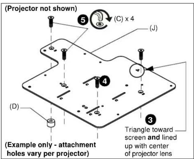
- Place the interface bracket (J) [with "C" markings visible] onto the bottom of the projector, aligning the mounting holes in the bracket with the spacers and threaded inserts in the bottom of the projector, and ensuring that triangle in bracket points towards screen, and lines up with center of the projector lens. (See Figure 1)
- Place four M4 x 16mm flat head cap screws (C) into the mounting holes marked as "2", through the spacers (D) and into the threaded inserts.
- Tighten all fasteners, securing the bracket to the projector.
text_image
(Projector not shown) (C) x 4 (J) (D) Example only - attachment holes vary per projector) Triangle toward screen and lined up with center of projector lensFigure 1
- Lift interface bracket (J) with Epson projector up to end of the existing SMART Board boom arm, and slide interface bracket slots (marked as "C") onto hooks. (See Figure 2)

text_image
SMART Board boom arm (remainder of arm not shown) (A) x 1 (J) 6 6 (Projector not shown)Figure 2
- Fasten interface bracket (J) to end of SMART Board boom arm through hole marked as "C" using one 1/4-20 x 1/2" button head cap screw (A). (See Figure 2)
- Adjust SMART Board boom arm to correct location according to projector model and SMART Board model, and following information in Table 1.
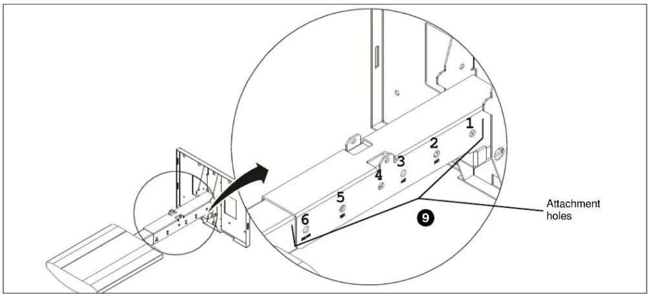
- Fasten SMART Board boom arm in place using hardware provided with SMART Board projector arm system. (See Figure 3)
text_image
Attachment holes 1 2 3 4 5 6 9Figure 3
Replacing SMART i5 Systems (UF75/UF75W Projectors)
Table 2: Replacing SMART i5 Systems (UF75/UF75W Projectors)
| SMART Board Models (i5 UF75 Series) | |||||||||||
| Mfr | Projector Model | Resolution | Throw Ratio | Aspect Ratio | Compatible SMART projector | SB660(4:3) | SB680SB880(4:3) | SB685SB885(16:10) | SB690(16:9) | Projector Pattern | Adapter Pattern |
| Epson | PowerLite 570 XGA 3LCD | XGA | 0.31-0.42 | 4:3 | UF75 | (64", 64") | (77", 77") | 1 | A | ||
| Epson | PowerLite 580 XGA 3LCD | XGA | 0.31-0.42 | 4:3 | UF75 | (64", 64") | (77", 77") | 1 | A | ||
| Epson | PowerLite 585W WXGA 3LCD | WXGA | 0.27-0.37 | 16:10 | UF75W | (87", 87") | (94", 94") | 1 | A | ||
See Figure 7 for boom arm positioning
Replacing SMART i5 Systems (UF75/UF75W Projectors)
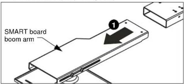
- Remove end of boom arm with projector attachment plate and save hardware. (See Figure 4)
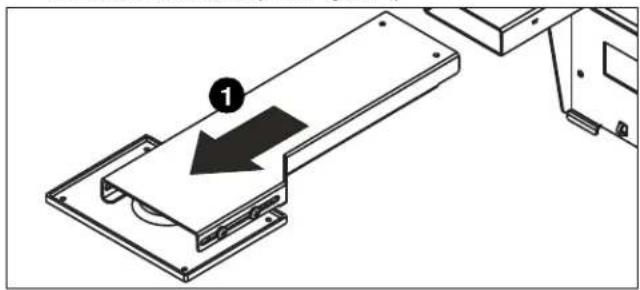
natural_image
Technical diagram showing a mechanical assembly with a labeled component (1) and directional arrow, no readable text or symbols present.Figure 4
- Turn projector upside down on a flat surface.
- Place four spacers (F) over the threaded inserts in the bottom of the projector.
- Place the interface bracket (J) [with "A" and "B" markings visible] onto the bottom of the projector, aligning the mounting holes (marked as "1") in the bracket with the spacers and threaded inserts in the bottom of the projector, and ensuring that triangle in bracket points towards screen, and lines up with center of the projector lens. (See Figure 5)
- Place four M4x35mm flat head screws (E) into the mounting holes marked as "1", through the spacers (F) and into the threaded inserts.
- Tighten all fasteners, securing the bracket to the projector.
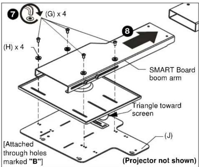
- Attach interface bracket (J) with attached projector to end of the existing SMART Board boom arm through the mounting holes marked as "A" using four M4 x 8mm button head cap screws (G) and four M4 washers (H). (See Figure 6)
- Slide SMART Board boom arm into the SMART board mount to correct location for both boom extension and height according to projector model and SMART Board model, and following information in Table 2. (See Figure 6)
- Use the hardware (saved in Step 1) to connect the boom arm to the SMART board mount. (See Figure 7)
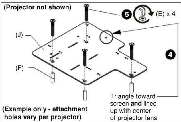
text_image
(Projector not shown) (E) x 4 (J) (F) (Example only - attachment holes vary per projector) Triangle toward screen and lined up with center of projector lensFigure 5
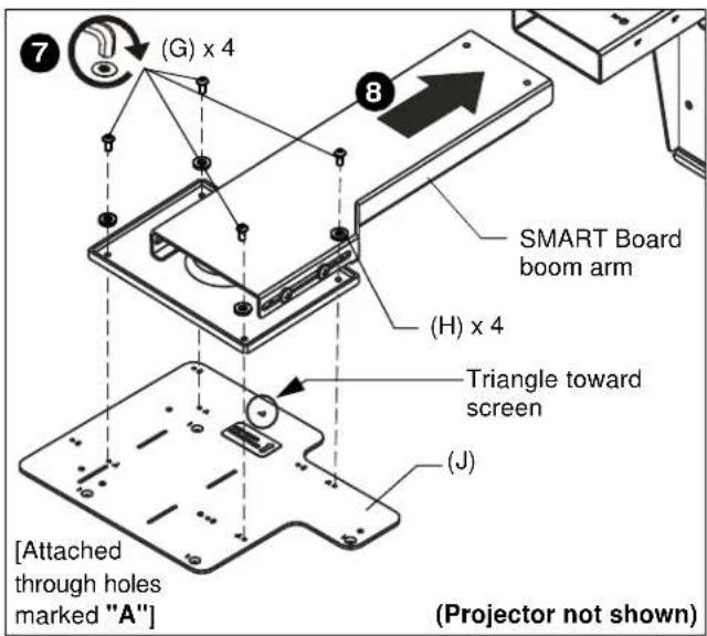
text_image
(G) x 4 8 SMART Board boom arm (H) x 4 Triangle toward screen (J) [Attached through holes marked "A"] (Projector not shown)Figure 6
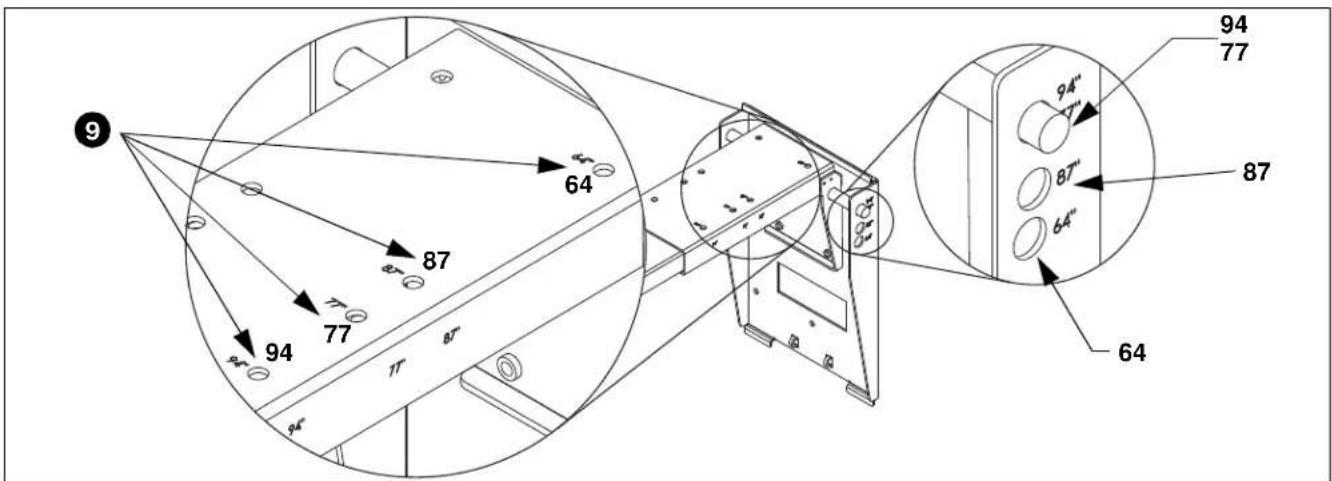
text_image
9 64 87 77 94 77 87 64 94" 7" 87" 64" 94 77Figure 7
Replacing SMART i5 Systems (UF70/UF70W Projectors)
Table 3: Replacing SMART i5 Systems (UF70/UF70W Projectors)
| Mfr | Projector Model | Resolution | Throw Ratio | Aspect Ratio | Compatible SMART projector | SB680 SB880 SBM680 (4:3) | SB685 SB885i SBM685 (16:10) | Projector Pattern | Adapter Pattern |
| Epson | PowerLite 570 XGA 3LCD | XGA | 0.31-0.42 | 4:3 | UF70/75 | (87", 87") | 1 | B | |
| Epson | PowerLite 580 XGA 3LCD | XGA | 0.31-0.42 | 4:3 | UF70/75 | (87", 87") | 1 | B | |
| Epson | PowerLite 585W WXGA 3LCD | WXGA | 0.27-0.37 | 16:10 | UF70W/75W | (87", 87") | 1 | B |
Replacing SMART i5 Systems (UF70/UF70W Projectors)
- Remove end of boom arm with projector attachment plate and save hardware. (See Figure 8)
text_image
SMART board boom armFigure 8
- Turn projector upside down on a flat surface.
- Place four spacers (F) over the threaded inserts in the bottom of the projector.
- Place the interface bracket (J) [with "A" and "B" markings visible] onto the bottom of the projector, aligning the mounting holes (marked as "1") in the bracket with the spacers and threaded inserts in the bottom of the projector, and ensuring that triangle in bracket points towards screen, and lines up with center of the projector lens. (See Figure 9)
- Place four M4x35mm flat head screws (E) into the mounting holes marked as "1", through the spacers (F) and into the threaded inserts. (See Figure 9)
- Tighten all fasteners, securing the bracket to the projector.
- Attach interface bracket (J) with attached projector to end of the existing SMART Board boom arm through the mounting holes marked as "B" using four M4 x 8mm button head cap screws (G) and four M4 washers (H). (See Figure 10)
- Slide SMART Board boom arm into the SMART board mount to correct location for both boom extension and height according to projector model and SMART Board model, and following information in Table 2. (See Figure 10)
- Use the hardware (saved in Step 1) to connect the boom arm to the SMART board mount. (See Figure 11)

text_image
(Projector not shown) (J) (E) x 4 (F) (Example only - attachment holes vary per projector) Triangle toward screen and lined up with center of projector lensFigure 9
text_image
(G) x 4 (H) x 4 SMART Board boom arm Triangle toward screen (J) [Attached through holes marked "B"] (Projector not shown)Figure 10

text_image
9 77 87 77 87" 11" 11" 94 77 87" 64" 94" 11" 87" 64"Figure 11
CLAUSE DE NON-RESPONSABILITÉ
text_image
E (4) M4 x 35mm F (4) .313 x .166 x 1.00 po G (4) M4 x 8mm H (4) (M4)
text_image
J (1) [support d'interface]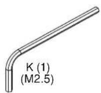
INSTALLATION

AVERTISSEMENT : TROP SERRER LES VIS PEUT ENDOMMAGER DES PIECES ET PEUT CAUSER DES BLESSURES OU ENDOMMAGER L'EQUIPEMENT ! SERREZ PAS TROP les vis en installant le support d'interface
natural_image
Technical line drawing of a mechanical assembly with a labeled component (no text or symbols present)Figure 4
A 6436 City West Parkway, Eden Prairie, MN 55344
P 800.582.6480
F 877.894.6918
E info@milestone.com (Soutien technique 7:00am - 7:00pm CST)
www.milestone.com
8800-002858 Rev01
12/16
DESCARGO DE RESPONSABILIDAD
natural_image
Technical diagram showing a mechanical assembly with a labeled component (1) and directional arrow, no readable text or symbols present.Figura 4
D 6436 City West Parkway, Eden Prairie, MN 55344
T 800.582.6480
F 877.894.6918
E info@milestone.com (Soporte técnico 7:00am - 7:00pm CST)
www.milestone.com
8800-002858 Rev01
12/16
AVISO LEGAL
The Ground Truth image displays a single, solid horizontal line. According to Rule 2 (UNDERSCORE & LINE RULES), if the GT contains lines used for stylistic emphasis or as background elements (like ruled paper), the OCR result must ignore them. The provided OCR content is "____", which consists of four underscores. This is incorrect because underscores are not equivalent to a solid line and are not permitted under the “Stylistic/Background Lines (Ignore)” rule. Outputting underscores for a stylistic line violates the rule and constitutes an error. Therefore, the OCR result is inconsistent with the Ground Truth.
Veja a Figura 3 para o posicionamento
do braço articulado
natural_image
Diagram showing a device being processed into a tray, with a numbered arrow indicating the process (no text or symbols present)Figura 4
E 6436 City West Parkway, Eden Prairie, MN 55344
T 800.582.6480
F 877.894.6918
A 6436 City West Parkway, Eden Prairie, MN 55344
P 800.582.6480
F 877.894.6918
E info@milestone.com (Tech Support 7:00am - 7:00pm CST)
www.milestone.com
8800-002858 Rev01
12/16