DGJ810CSBD - Grill plate Dyna-Glo - Free user manual and instructions
Find the device manual for free DGJ810CSBD Dyna-Glo in PDF.
| Product Type | Dual Fuel Barbecue (Gas and Charcoal) |
| Brand | Dyna-Glo |
| Model | DGJ810CSBD |
| Assembled Product Dimensions | 70 cm (W) x 186.3 cm (D) x 128.4 cm (H) |
| Product Weight | 58 kg |
| Energy Source | Propane gas (tank not included) and charcoal |
| Main Burner – BTU/h | 36,000 BTU/h (total) |
| Side Burner – BTU/h | 12,000 BTU/h |
| Number of Main Burners | 4 |
| Side Burner | 1 |
| Ignition Type | Electronic (AA battery) and match |
| Main Burner Material | Stainless steel |
| Cooking Grates Material | Porcelain |
| Main Features | Dual fuel, warming rack, adjustable charcoal tray, side burner, grate hook |
| Maintenance and Cleaning | Burner cleaning, grease tray, cooking grates, exterior surfaces |
| Safety | Leak detection, safety distance 91.44 cm, never use indoors |
| Warranty | 1 year (5 years on stainless steel burners) |
| Spare Parts | Available through customer service |
| Included Accessories | Cooking grates (4), heat plates (3), grease tray, grease cup, grate hook, crank, storage basket |
| Wheels | 4 wheels (2 with brake) |
| Usage | Outdoor only |
Frequently Asked Questions - DGJ810CSBD Dyna-Glo
User questions about DGJ810CSBD Dyna-Glo
0 question about this device. Answer the ones you know or ask your own.
Ask a new question about this device
Download the instructions for your Grill plate in PDF format for free! Find your manual DGJ810CSBD - Dyna-Glo and take your electronic device back in hand. On this page are published all the documents necessary for the use of your device. DGJ810CSBD by Dyna-Glo.
USER MANUAL DGJ810CSBD Dyna-Glo
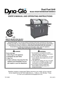
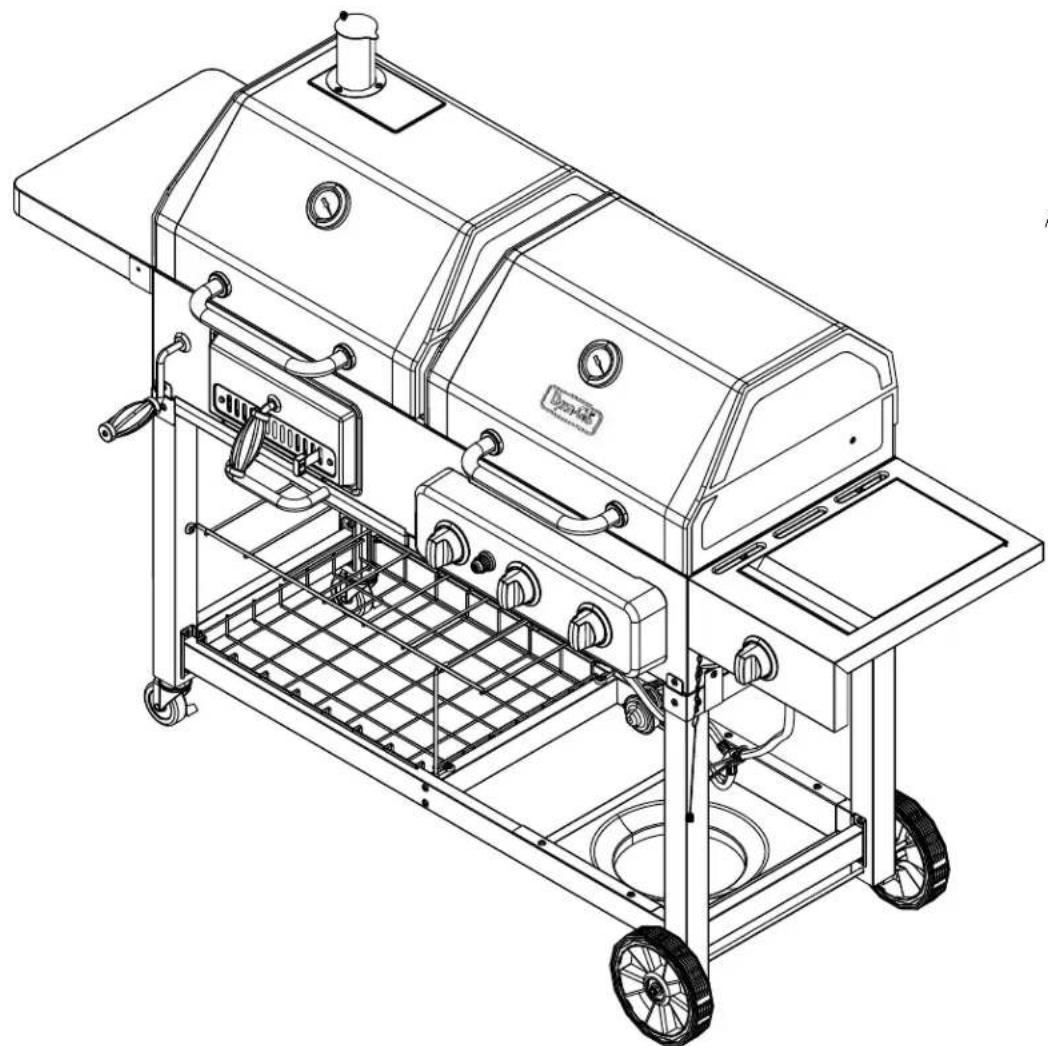
natural_image
Technical line drawing of a portable electric stove with wheels and internal components (no text or symbols)
C US
ANS Z21.58b-2012
CSA 1.6b-2012
ATTACH YOUR RECEIPT HERE
Serial Number ____ Purchase Date ____

Questions, problems, missing parts? Before returning to your retailer, call our customer service department at 1-877-447-4768, 8:30 a.m. – 4:30 p.m. CST, Monday – Friday.
70-10-0??
Package Contents 3
Hardware Contents.... 5
Safety Information 5
Preparation....7
Assembly Instructions....9
Operating Instructions 23
Care and Maintenance 30
Troubleshooting....33
Warranty 35
Replacement Parts List 36
Assembler/Installer: This instruction manual contains important information necessary for the proper assembly and safe use of this appliance. Read and follow all warnings and instructions before assembling and using this appliance. Leave these instructions with the consumer.
Consumer/User: Follow all warnings and instructions when using this appliance. Keep these instructions for future reference.

GER
If you smell gas:
-
Shut off gas to the appliance.
-
Extinguish open flame.
-
Open lid.
-
If odor continues, keep away from the appliance and immediately call your gas supplier or your fire department.
WARNING!
-
Do not store or use gasoline or other flammable liquids or vapors in the vicinity of this or any other appliance.
-
An LP cylinder not connected for use shall not be stored in the vicinity of this or any other appliance.
-
This grill is for outdoor use only and shall not be used in a building, garage, under overhangs or any other enclosed area.
-
Do not leave a lit grill unattended. Keep children and pets away from the grill at all times.
WARNING
-
Never operate this appliance unattended.
-
Never operate this appliance within 3 feet (1 m) of any structure, combustible material or other gas cylinder.
-
Never operate this appliance within 25 feet (7.5 m) of any flammable liquid.
-
If a fire should occur, keep away from the appliance and immediately call your fire department. Do not attempt to extinguish an oil or grease fire with water.

DANGER:
Failure to follow these instructions could result in fire, explosion, or burn hazard which could cause property damage, personal injury or death.
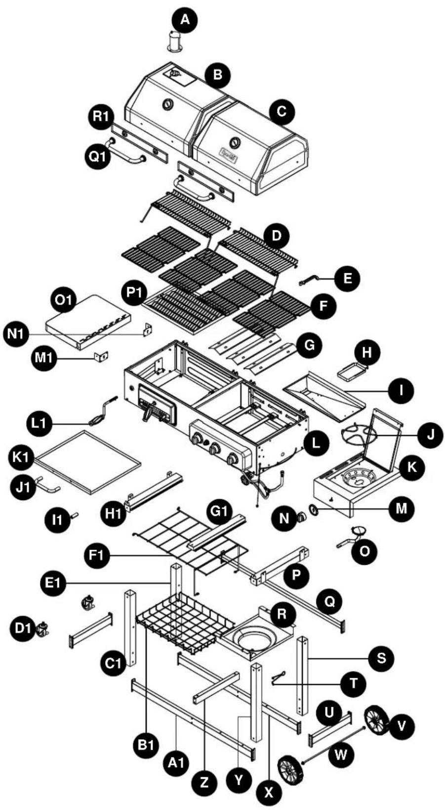
| PART DESCRIPTION QUANTITY | ||
| A Smoke stack 1 | ||
| B Charcoal grill lid 1 | ||
| C Gas grill lid 1 | ||
| D Warming rack 2 | ||
| E Cooking grate hook 1 | ||
| F Cooking grate 4 | ||
| G Heat tent 3 | ||
| H Grease cup 1 | ||
| I | Grease pan | 1 |
| J | Side burner cooking grate 1 | |
| K Right side burner table | 1 | |
| L Firebox | 1 | |
| M | Side burner knob bezel | 1 |
| N Side burner control knob | 1 | |
| O Side burner | 1 | |
| P Right cart brace | 1 | |
| Q Rear cart brace | 1 | |
| R Tank shelf | 1 | |
| S Right rear leg | 1 | |
| T Hose retention wire | 1 | |
| U Bottom brace (left/right) | 2 | |
| V Wheel | 2 | |
| W | Axle | 1 |
| X Rear bottom brace | 1 | |
| Y Right front leg 1 | ||
| Z Middle bottom brace | 1 | |
| PART DESCRIPTION QUANTITY | ||
| A1 | Front bottom brace | 1 |
| B1 | Storage basket | 1 |
| C1 | Left front leg | 1 |
| D1 | Locking caster 2 | |
| E1 | Left rear leg | 1 |
| F1 | Intermediate shelf | 1 |
| G1 | Firebox support | 1 |
| H1 | Left cart brace | 1 |
| I1 | Battery | 1 |
| J1 | Ash tray handle | 1 |
| K1 | Ash tray | 1 |
| L1 | Crank handle | 1 |
| M1 | Left side table support (front) | 1 |
| N1 | Left side table support (rear) | 1 |
| O1 | Left side table | 1 |
| P1 | Charcoal tray | 1 |
| Q1 | Lid handle | 2 |
| R1 | Lid handle heat shield | 2 |
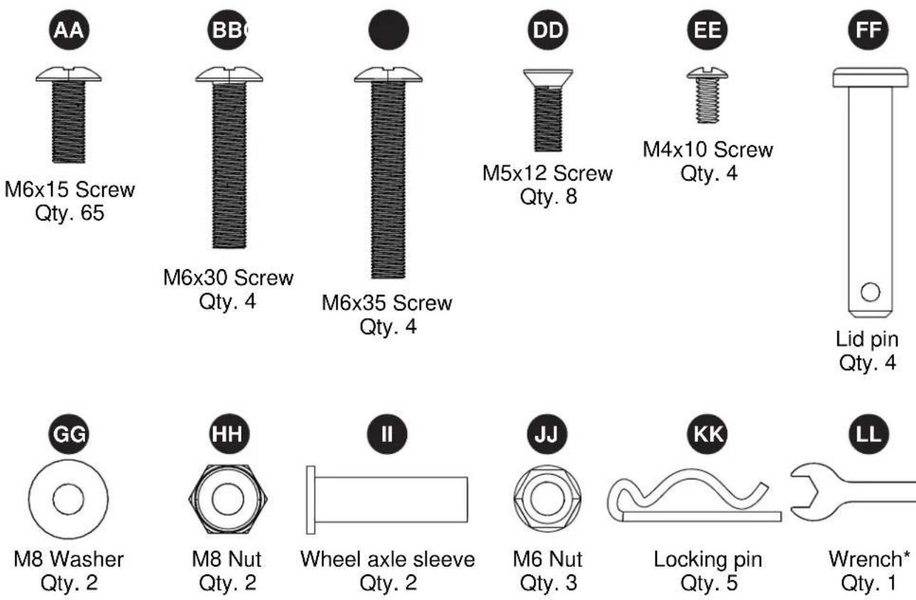

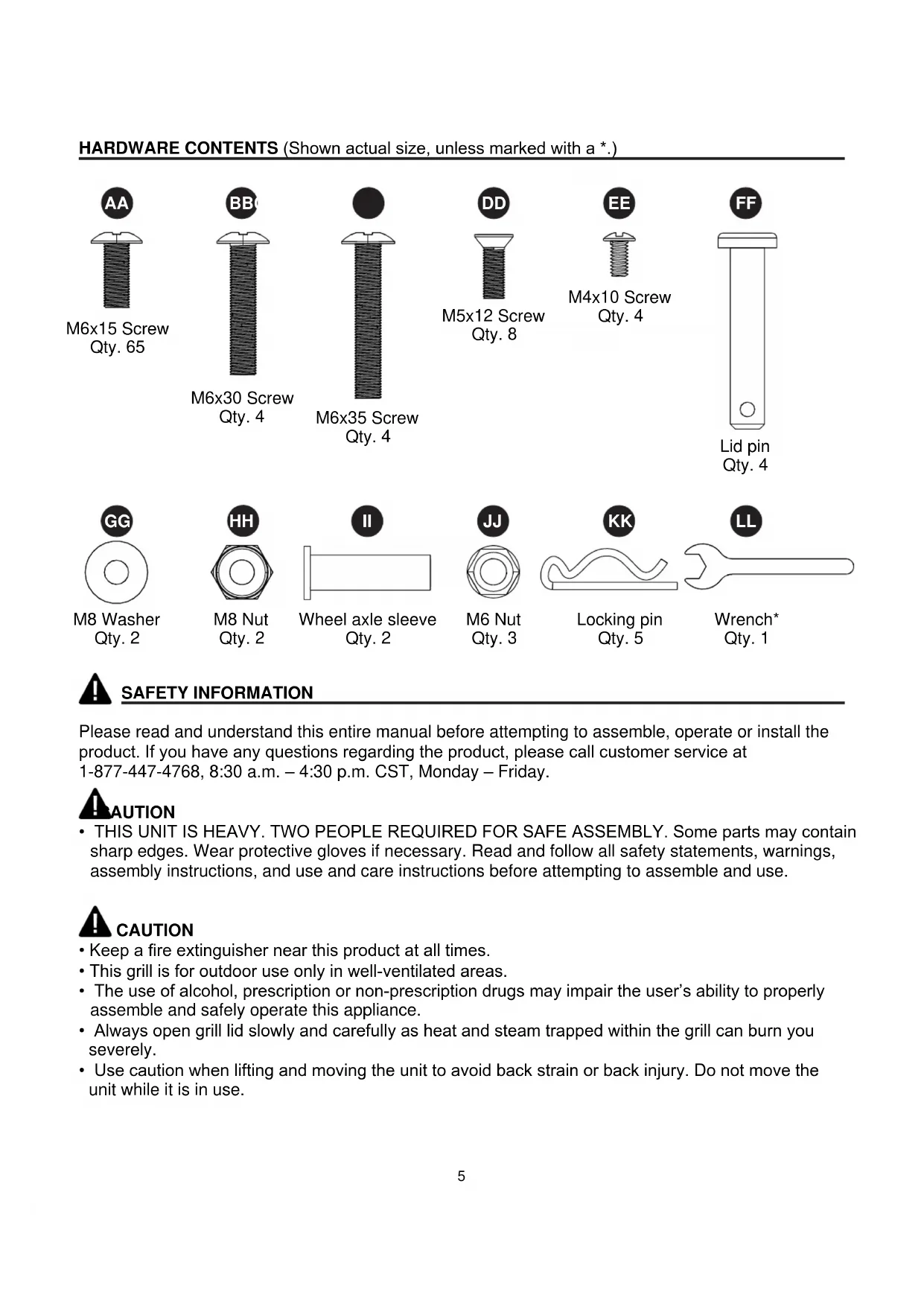
SAFETY INFORMATION
Please read and understand this entire manual before attempting to assemble, operate or install the product. If you have any questions regarding the product, please call customer service at 1-877-447-4768, 8:30 a.m. – 4:30 p.m. CST, Monday – Friday.
!AUTION
- THIS UNIT IS HEAVY. TWO PEOPLE REQUIRED FOR SAFE ASSEMBLY. Some parts may contain sharp edges. Wear protective gloves if necessary. Read and follow all safety statements, warnings, assembly instructions, and use and care instructions before attempting to assemble and use.
CAUTION
- Keep a fire extinguisher near this product at all times.
- This grill is for outdoor use only in well-ventilated areas.
- The use of alcohol, prescription or non-prescription drugs may impair the user's ability to properly assemble and safely operate this appliance.
• Always open grill lid slowly and carefully as heat and steam trapped within the grill can burn you severely. - Use caution when lifting and moving the unit to avoid back strain or back injury. Do not move the unit while it is in use.

SAFETY INFORMATION
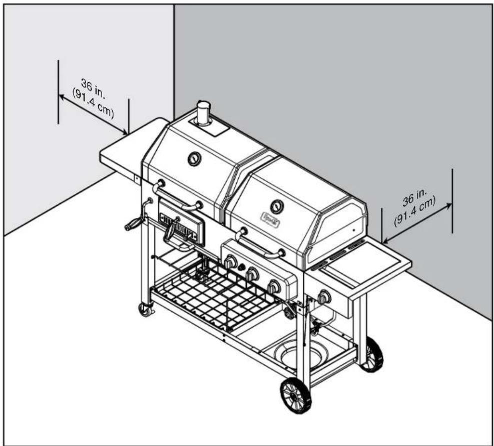
- DO NOT operate the unit near or under flammable or combustible materials such as decks, porches or carports. A minimum clearance of 36 in. (91.44 cm) is recommended. DO NOT operate the unit under overhead construction.
- A minimum clearance to combustible construction is 36 in. (91.44 cm) from sides and back.
- DO NOT use this appliance as a heater.
- DO NOT obstruct the flow of combustion air or ventilation air for the appliance.
- Care should be taken to protect the fuel supply hose from damage from either pedestrian or vehicle traffic.
- Clean and inspect the hose before each use of the appliance. If there is evidence of abrasion, wear, cuts or leaks, the hose must be replaced prior to the appliance being used. The replacement hose assembly shall be that specified by the manufacturer.
- Move gas hoses as far away as possible from hot surfaces and dripping hot grease.
- NEVER keep a filled container in a hot car or car trunk. Heat will cause the gas pressure to increase, which may open the relief valve and allow gas to escape.
- Keep the grill's valve compartment, burners and circulating air passages clean. Inspect the grill before each use. Do not obstruct the flow of gas or ventilation air.
- The propane grill side is for use with propane gas only (propane gas cylinder not included).
- Always hang the regulator on the tank retention wire while not in use or disconnected with the LP (liquid propane) tank. KEEP the fuel supply hose away from any heated surface(s).
- An LP cylinder not connected for use should be stored a minimum of 10 feet (3 m) away from this or any other appliance.
- NEVER attempt to attach this grill to the self-contained propane system of a boat, camper trailer, motor home or house.
- Operate the unit on a stable, level, non-flammable surface such as asphalt, concrete or solid ground. DO NOT operate the unit on flammable material such as carpet or a wood deck.
- Use caution when assembling and operating this unit to avoid cuts and scrapes from edges.
- DO NOT use the grill unless it is completely assembled and all parts are securely fastened and tightened.
- Keep all combustible items and surfaces at least 36 inches (91.44 cm) away from the grill at all times.
- DO NOT use in an explosive atmosphere. Keep grill area clear and free from combustible materials, gasoline and other flammable vapors and liquids.
- DO NOT touch metal parts of grill until it has completely cooled (about 45 minutes) to avoid burns, unless you are wearing protective gear (pot holders, gloves, BBQ mittens, etc.).
• DO NOT alter this grill in any manner. - DO NOT use this product in a manner other than its intended purpose. It is NOT intended for commercial use. It is not intended to be installed or used in or on a recreational vehicle and/or boats.
- DO NOT store or use gasoline or any other flammable vapors and liquids within 25 feet (8 m) of this or any other appliance.
- DO NOT store or operate this product in an area accessible to children or pets. Store this unit in a dry, protected location.
- DO NOT leave the unit unattended while in use. Keep children and pets away while the grill is in use.
- DO NOT leave hot ashes unattended until the grill cools completely.
- DO NOT move the unit while in use or while ashes are still hot. Allow the unit to cool completely before moving or storing.
- NEVER use charcoal lighter fluid with the grill.

SAFETY INFORMATION
- DO NOT use gasoline, kerosene or alcohol for lighting. The LP gas supply cylinder used with this appliance must be:
(a) Constructed and marked in accordance with the Specifications for LP-Gas Cylinders of the U.S. Department of Transportation (D.O.T.) or the National Standard of Canada, CAN/CSA-B339, Cylinders, Spheres and Tubes for Transportation of Dangerous Goods; and Commission, as applicable; and
(b) Provided with a listed overfilling prevention device.
(c) Provided with a cylinder connection device compatible with the connector for outdoor cooking appliances. This grill is not intended to be used in or installed on recreational vehicles and/or boats.
• Always cook your food on the grate after the charcoal flames have burned out.
- Dispose of cold ashes by wrapping them in heavy-duty aluminum foil and placing in a noncombustible container. Make sure there are no other combustible materials in or near the container.
- If you must dispose of ashes in less time than it takes for the ashes to completely cool down, then remove the ash tray with heat-resistant gloves and place the ashes in heavy-duty foil. Soak the ashes completely with water before disposing of them in a noncombustible container.
- DO NOT leave a lit grill unattended. Keep children and pets away from the grill at all times.
- DO NOT place this grill on any type of tabletop surface. The grill should be placed on a flat and level surface.
• DO NOT use the grill in high winds.
- DO NOT modify this grill for use with other indoor or outdoor fixtures, such as countertops or drop-in grill islands.
- Allow the unit to cool completely before conducting any routine cleaning or maintenance.
• DO NOT use this grill indoors.
CALIFORNIA PROPOSITION 65
- Fuels used in gas, oil fired, wood burning, and charcoal burning appliances and the products of combustion of such fuels contain chemicals known to the state of California to cause cancer, birth defects or other reproductive harm. This product contains chemicals, including lead and lead compounds, known to the state of California to cause cancer, birth defects or other reproductive harm. Wash hands after handling.
PREPARATION
Before beginning assembly of product, make sure all parts are present. Compare parts with package contents list and hardware contents list. If any part is missing or damaged, do not attempt to assemble the product.
Estimated Assembly Time: 45 minutes with two people
Tools Required for Assembly (not included): Phillips screwdriver, adjustable wrench.
DO NOT place the grill under overhead combustible construction or awnings. Minimum clearance from sides and back of unit to combustible construction is 36 in. (91.4 cm). All of the above noted clearances are with respect to combustible wood structures or construction. Greater clearances are recommended for vinyl structures or construction.
NOTE: The installation must conform with local codes or, in the absence of local codes, with either the National Fuel Gas Code, ANSI Z223.1/NFPA 54, Natural Gas and Propane Installation Code, CSA B149.1, or Propane Storage and Handling Code, B149.2.

DANGER
CARBON MONOXIDE HAZARD
Burning charcoal inside can kill you. It gives off carbon monoxide, which has no odor. NEVER burn charcoal inside homes, vehicles, or tents.
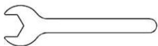
- Attach left front leg (C1) and left rear leg (E1) to bottom brace (U) and secure using four M6x15 screws (AA).
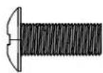
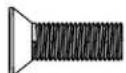
Hardware Used

M6x15 Screw

x 4
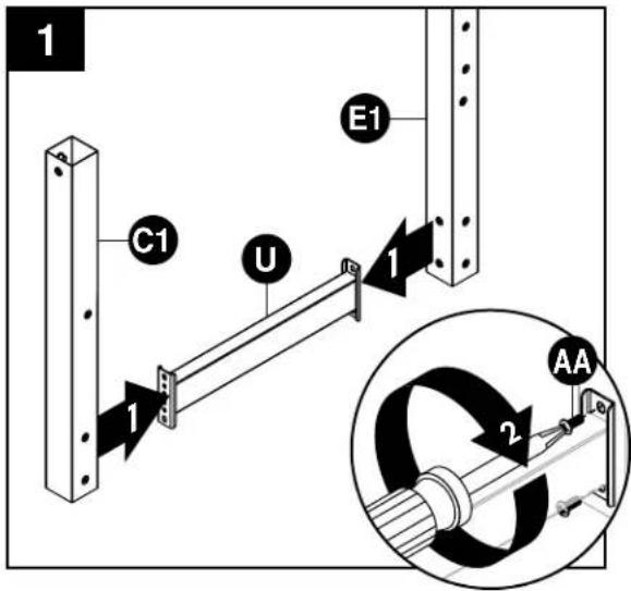
- Attach left cart brace (H1) to left front leg (C1) and left rear leg (E1) and secure using four M6x15 screws (AA). Repeat steps 1 and 2 for right legs (S/Y) and right braces (U/P).
Hardware Used

M6x15 Screw

x 12
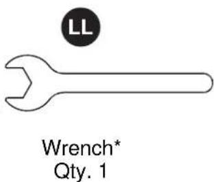
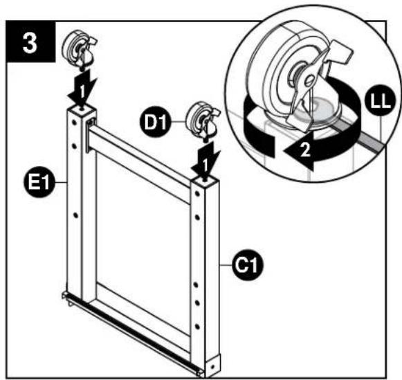
- Flip left leg assembly upside down. Attach locking casters (D1) to left front leg (C1) and left rear leg (E1) using wrench (LL).
Hardware Used

Wrench
x 1
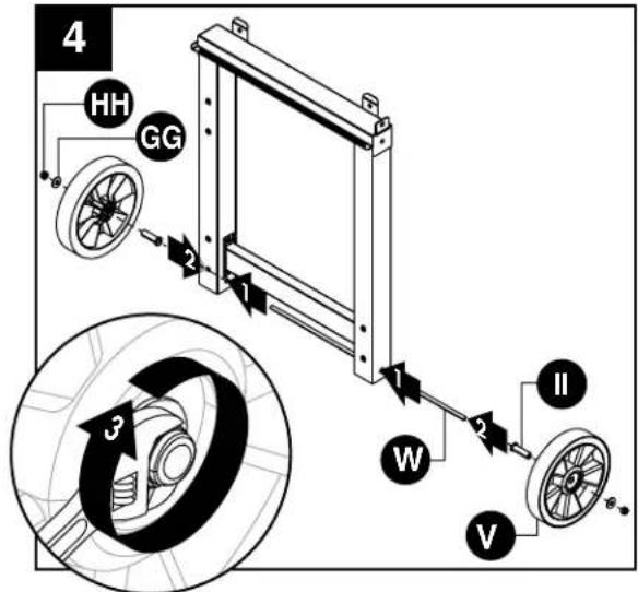
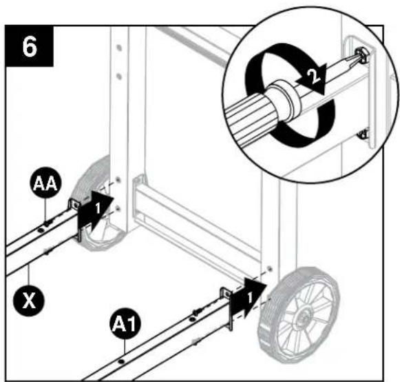
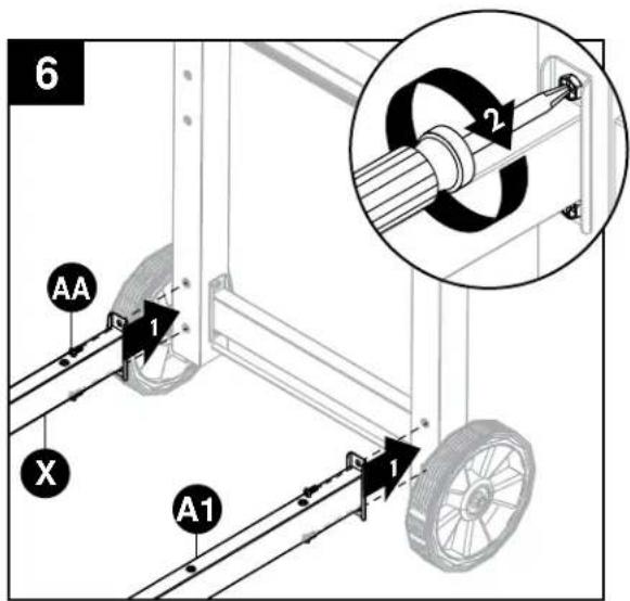
- Insert axle (W) into right leg assembly. Attach one wheel (V) to each side of axle (W) using one wheel axle sleeve (II), one M8 washer (GG), and one M8 nut (HH).
Hardware Used
| II | Wheel axle sleeve | 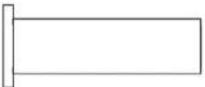 | x 2 |
| GG | M8 Washer | x 2 | |
| HH | M8 Nut | x 2 |
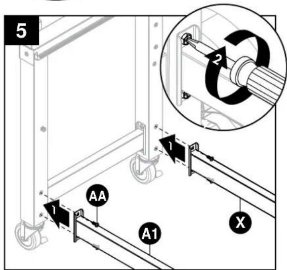
- Attach front bottom brace (A1) and rear bottom brace (X) to left leg assembly using two M6x15 screws (AA) on each side.
Hardware Used
| AA | M6x15 Screw | 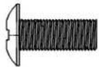 | x 4 |
- Attach front bottom brace (A1) and rear bottom brace (X) to right leg assembly using two M6x15 screws (AA) on each side.
Hardware Used
| AA | M6x15 Screw |  | × 4 |
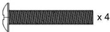
- Attach middle bottom brace (Z) to front bottom brace (A1) and rear bottom brace (X) and secure using four M6x35 screws (CC).
Hardware Used

M6x35 Screw
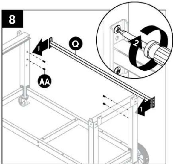
- Attach rear cart brace (Q) to left and right leg assemblies and secure using four M6x15 screws (AA).
Hardware Used

M6x15 Screw

x 4
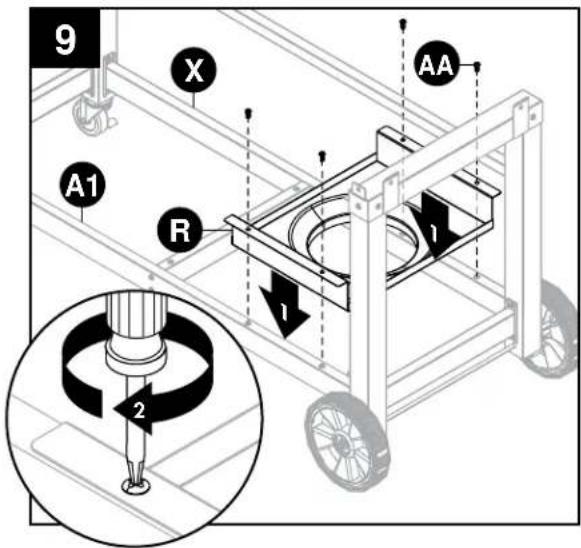
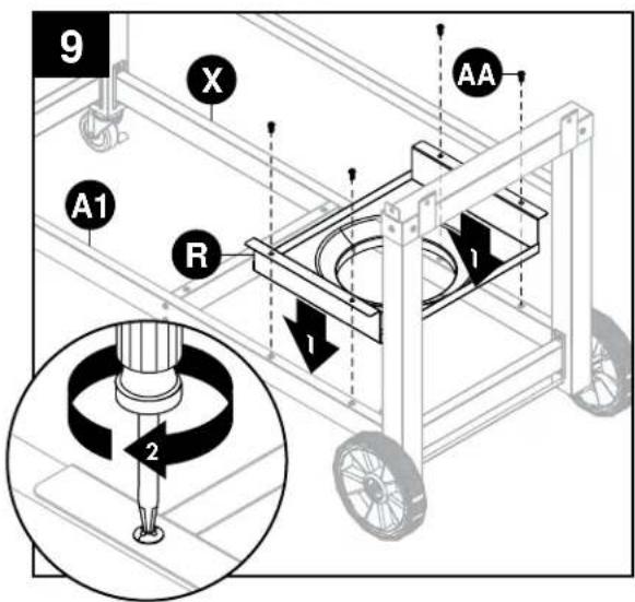
- Attach tank shelf (R) to front bottom brace (A1) and rear bottom brace (X) and secure using four M6x15 screws (AA).
Hardware Used

M6x15 Screw

x 4
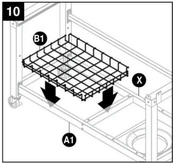
-
Place storage basket (B1) onto front bottom brace (A1) and rear bottom brace (X).
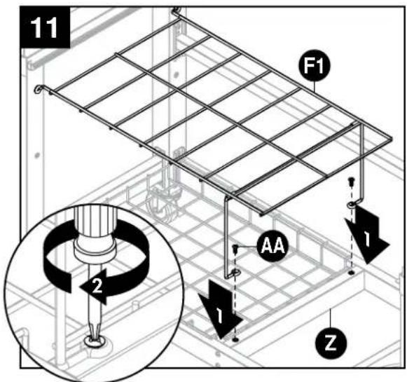
-
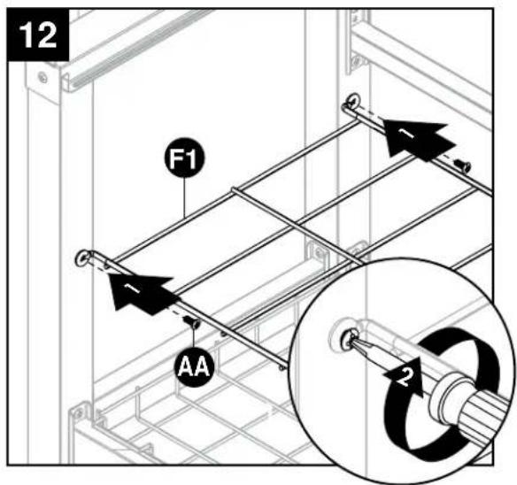
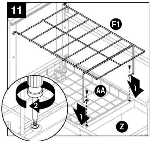
Attach intermediate shelf (F1) to middle bottom brace (Z) and secure using two M6x15 screws (AA).
Hardware Used

M6x15 Screw

x 2
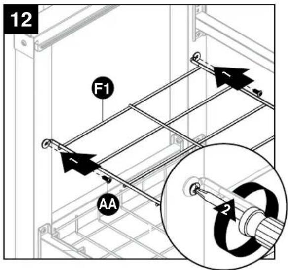
- Secure intermediate shelf (F1) to left leg assembly using two M6x15 screws (AA).
Hardware Used

M6x15 Screw

x 2
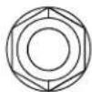
- Attach lid handle (Q1) and lid handle heat shield (R1) to charcoal grill lid (B) using two M6x15 screws (AA). Repeat for gas grill lid (C).
Hardware Used

M6x15 Screw

x 4
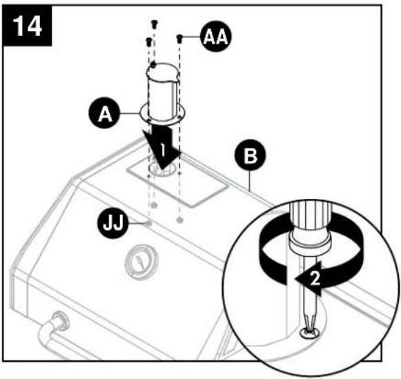
- Attach smoke stack (A) to charcoal grill lid (B) and secure using three M6x15 screws (AA) and three M6 nuts (JJ).
Hardware Used

M6x15 Screw

x 3

M6 Nut
x 3
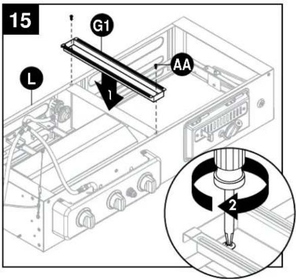
- Turn firebox (L) upside down. Attach firebox support (G1) to firebox (L) and secure using two M6x15 screws (AA).
Hardware Used

M6x15 Screw
x 2
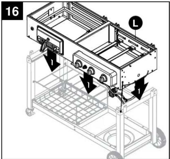
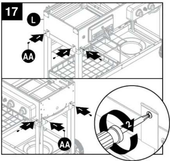
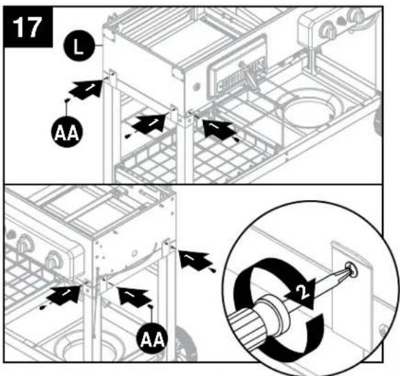
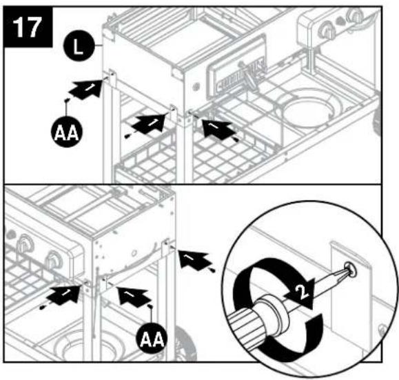
-
Position firebox (L) on cart assembly. Make sure the hose and regulator is not in between the firebox (L) and cart assembly.
-
Secure firebox (L) to cart assembly using six M6x15 screws (AA).
Hardware Used

M6x15 Screw
x 6
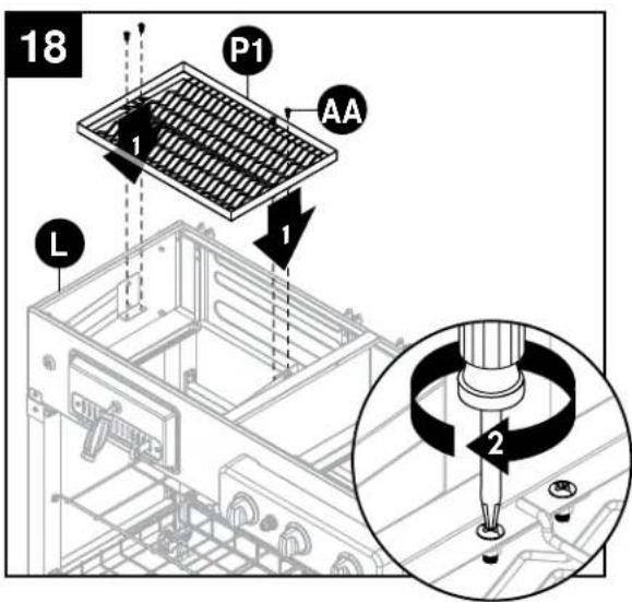
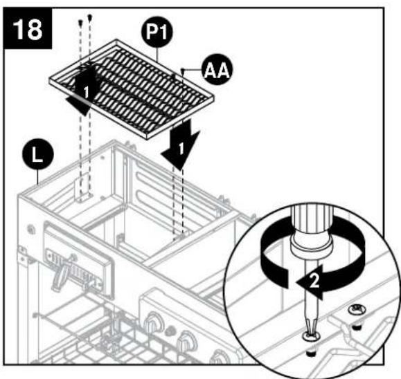
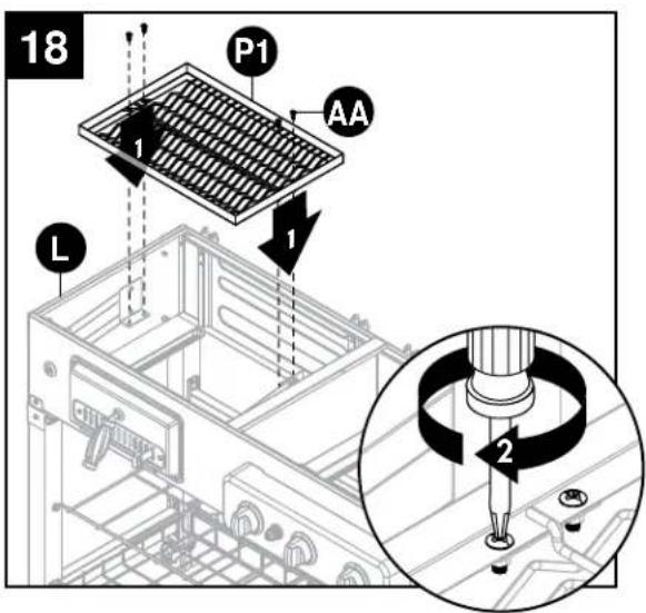
- Attach charcoal tray (P1) to firebox (L) and secure using four M6x15 screws (AA).
Hardware Used

M6x15 Screw

x 4
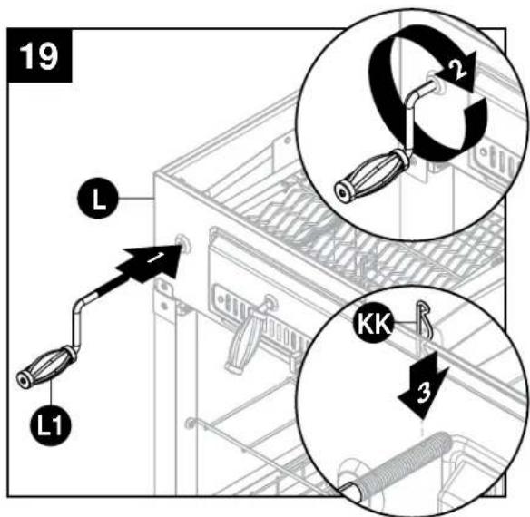
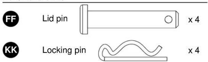
- Attach crank handle (L1) to firebox (L) and secure using one locking pin (KK).
Hardware Used

Locking pin
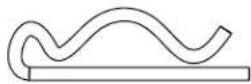
x 1
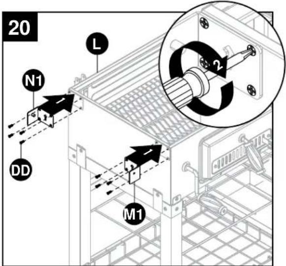
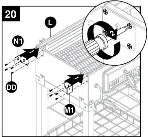
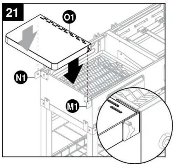
- Attach left side table supports (M1/N1) to firebox (L) and secure using eight M5x12 screws (DD).
Hardware Used

M5x12 Screw
x 8
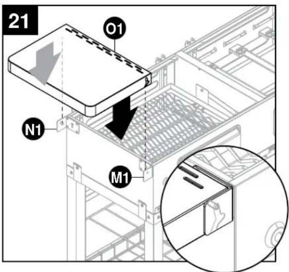
- Align notches in left side table (O1) with left side table supports (M1/N1) and secure.
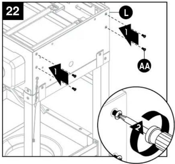
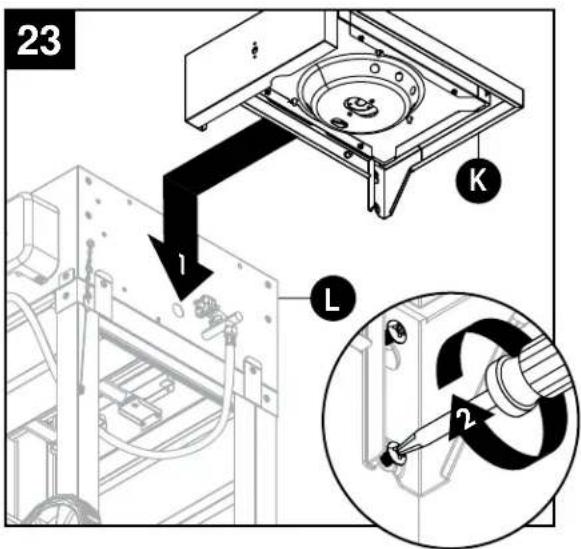
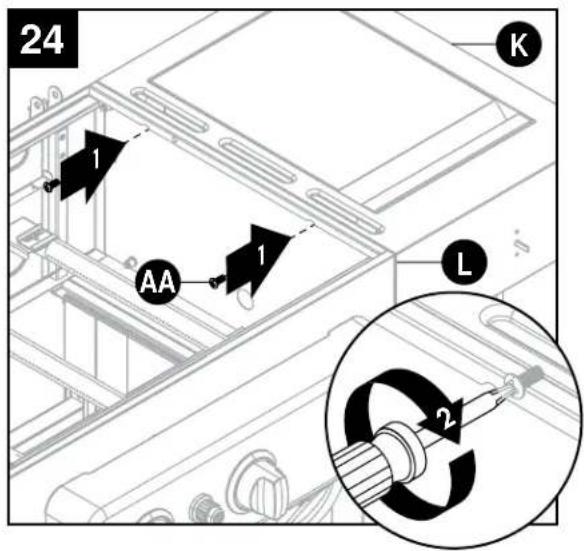
- Partially insert four M6x15 screws (AA) into the right side of firebox (L). DO NOT fully tighten screws (leave approximately 5 mm).
Hardware Used

M6x15 Screw

x 4
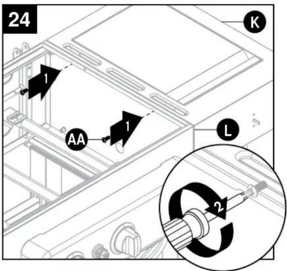
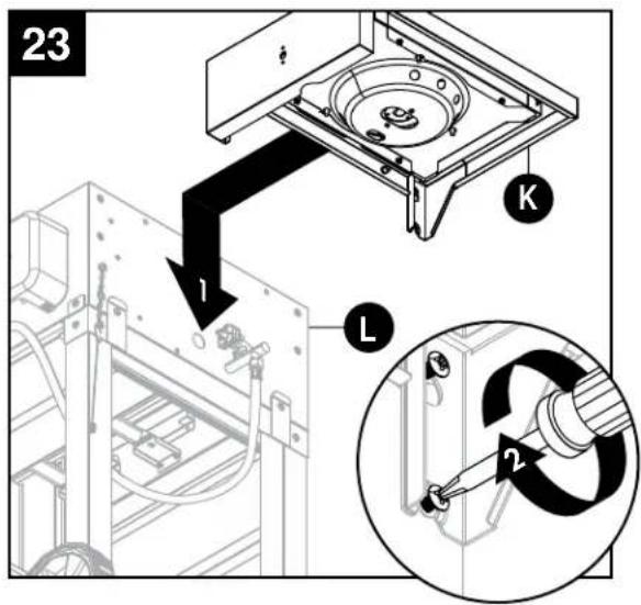
-
Align the key holes in the right side burner table (K) with the four M6x15 screws (AA) just installed in the firebox (L). Tighten M6x15 screws (AA).
-
Secure right side burner table (K) to firebox (L) using two M6x15 screws (AA).
Hardware Used

M6x15 Screw

x 2

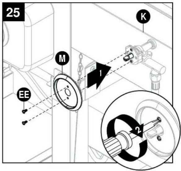
- Attach side burner knob bezel (M) and side burner valve to right side burner table (K) and secure using two M4x10 screws (EE).
Hardware Used

M4x10 Screw

x 2
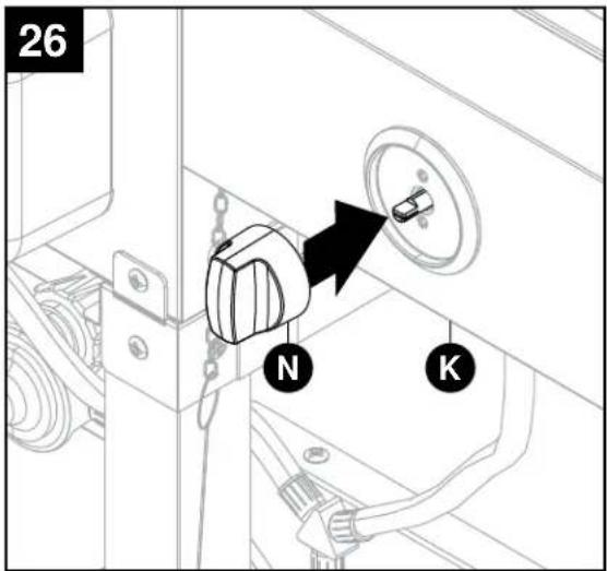
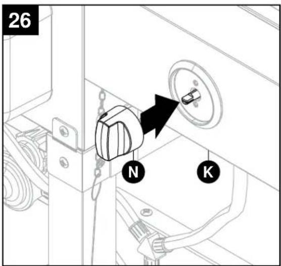
-
Install side burner control knob (N) to right side burner table (K).
-
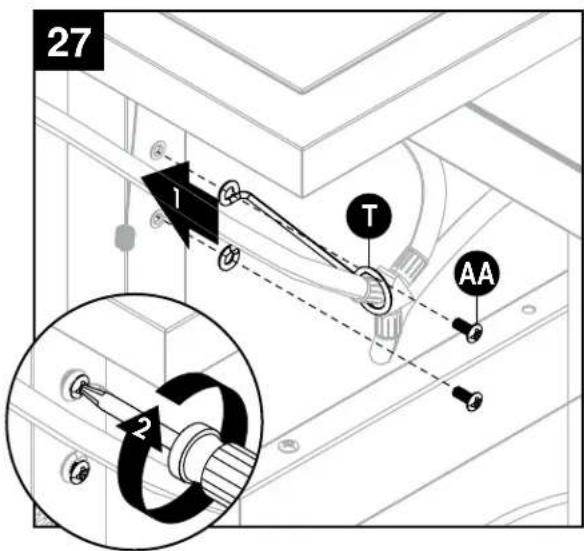
Attach hose retention wire (T) to right front leg (Y) and secure using two M6x15 screws (AA).
Hardware Used

M6x15 Screw

x 2
-
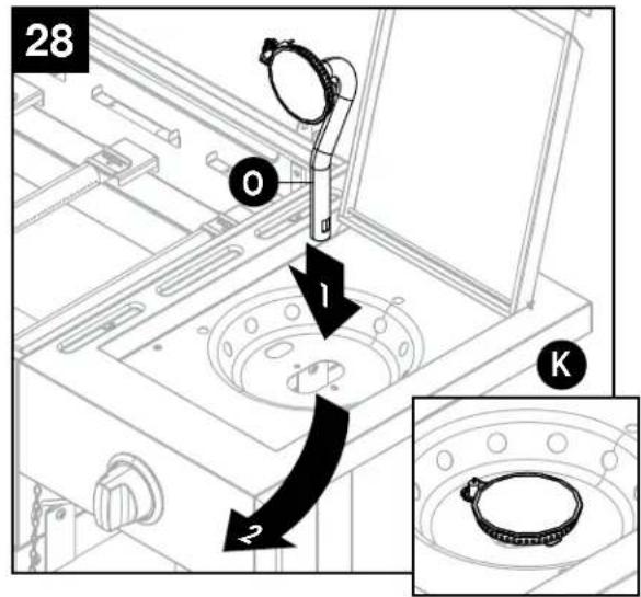
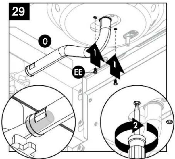
Install side burner (O) to right side burner table (K).
-
Secure side burner (O) to right side burner table (K) using two M4x10 screws (EE). Make sure side burner (O) is connected to side burner valve.
Hardware Used

M4x10 Screw

x 2
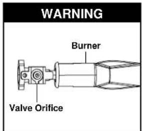
WARNING: IT IS VERY IMPORTANT TO CHECK AND ENSURE THAT THE SIDE BURNER IS FULLY ENGAGED WITH THE ADJACENT VALVE ORIFICE BEFORE COMPLETING STEP 29 AND 30. FAILURE TO DO SO MAY RESULT
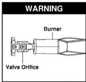
IN FIRE OR EXPLOSION, POSSIBLY CAUSING SERIOUS INJURY OR DEATH. REFER TO MAINTENANCE SECTION INSTRUCTIONS TO PROPERLY CHECK THE ENGAGEMENT.
-
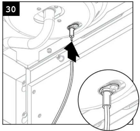
Insert side burner ignition wire to side burner electrode.
-
Place side burner cooking grate (J) onto right side burner table (K).
-
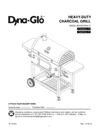
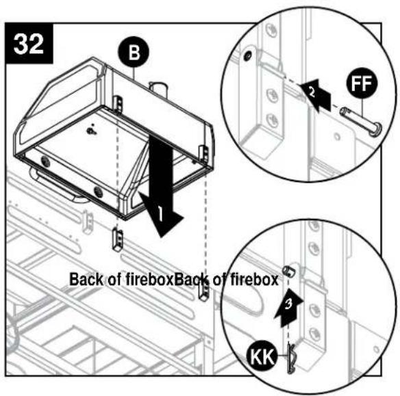
Attach charcoal grill lid (B) to firebox (L) using two lid pins (FF) and two locking pins (KK). Repeat for gas grill lid (C).
Hardware Used

natural_image
Technical diagram showing pipe installation with a black arrow pointing to a cable, plus an inset close-up of the cable (no text or symbols)
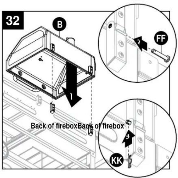
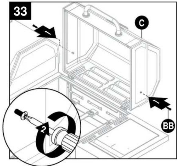
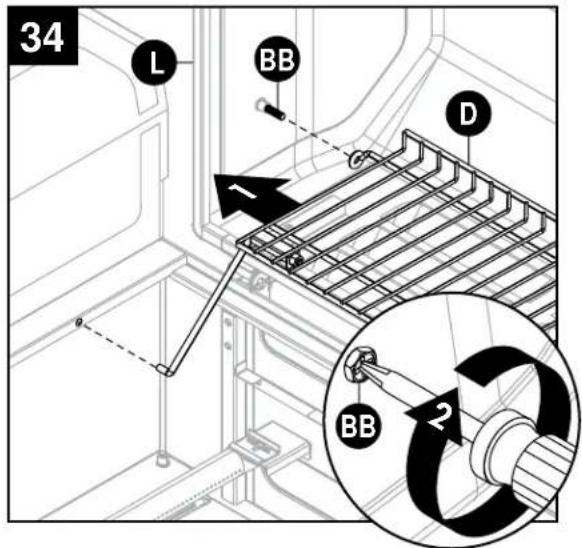
- Open gas grill lid (C) and partially insert two M6x30 screws (BB). Repeat for charcoal grill lid (B).
Hardware Used

M6x30 Screw
x 4
-
From the inside of the firebox (L), attach the end of the warming rack (D) onto the screw (BB) and tighten. Insert the bottom warming rack supports into the holes located on firebox (L). Repeat for charcoal grill lid (B).
-
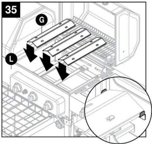
Install three heat tents (G) into firebox (L).

WARNING: IT IS VERY IMPORTANT TO CHECK AND ENSURE THAT THE SIDE BURNER IS FULLY ENGAGED WITH THE ADJACENT VALVE ORIFICE BEFORE COMPLETING STEP 35. FAILURE TO DO SO MAY RESULT IN FIRE OR EXPLOSION,
POSSIBLY CAUSING SERIOUS INJURY OR DEATH. REFER TO MAINTENANCE SECTION INSTRUCTIONS TO PROPERLY CHECK THE ENGAGEMENT.
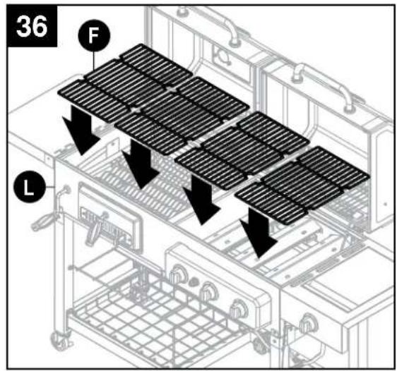
-
Place four cooking grates (F) onto firebox (L).
-
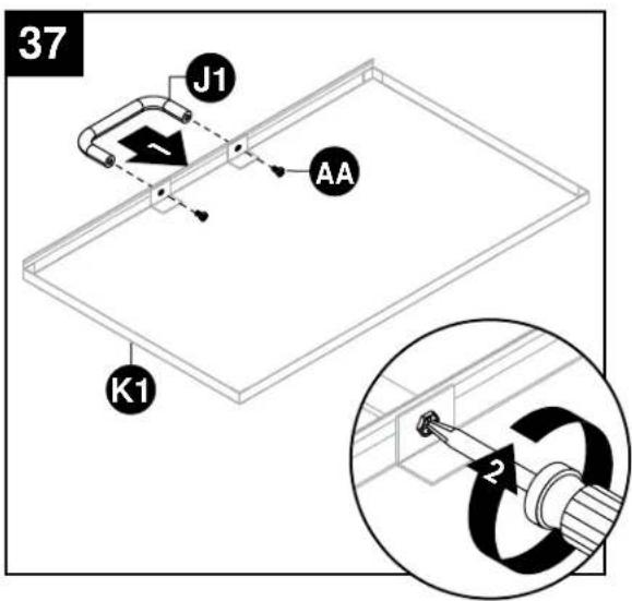
Attach ash tray handle (J1) to ash tray (K1) and secure using two M6x15 screws (AA).
Hardware Used

M6x15 Screw
x 2
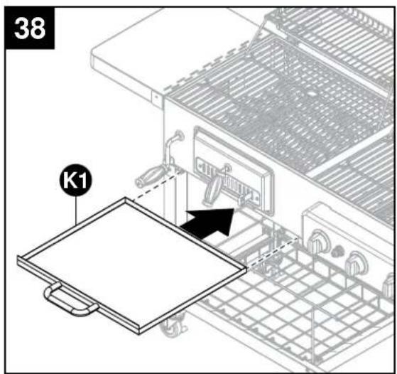
- Insert ash tray (K1) into charcoal grill firebox.
-
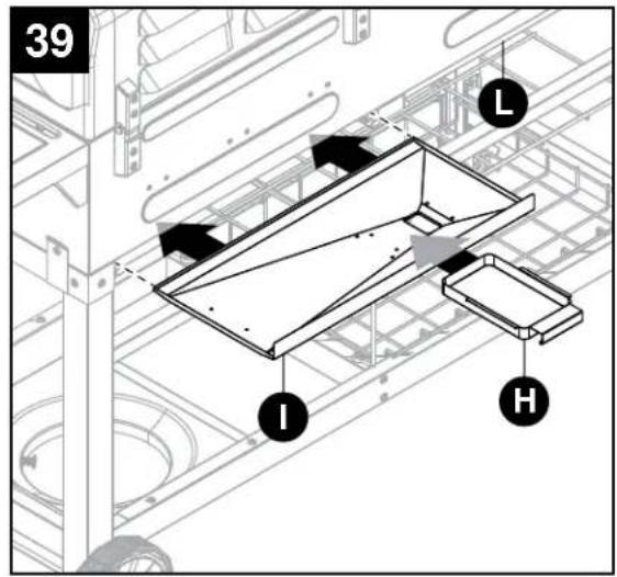
Insert the grease pan (I) into position by sliding it in the firebox (L) from the rear along the rails. Insert the grease cup (H) into position by sliding it onto the rails located on the bottom side of the grease pan (I).
-
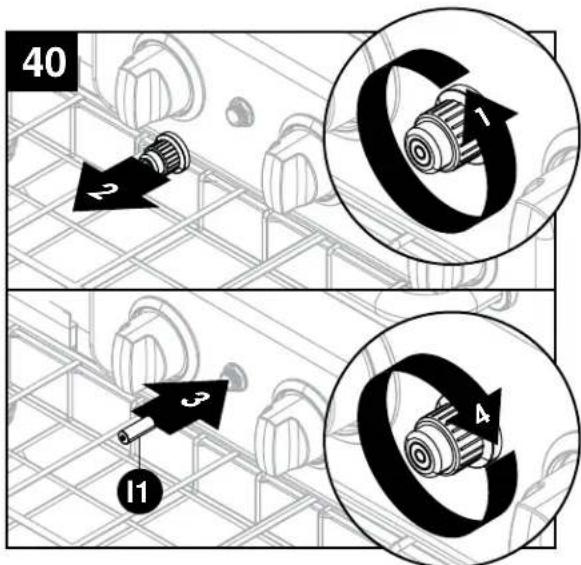
Remove the igniter cap by turning it counterclockwise. Insert the AA battery (I1) into the igniter body with positive (+) end facing out. Replace the igniter cap.
-
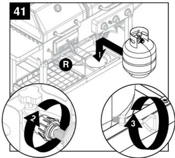
Insert the LP gas cylinder (sold separately) into the nesting hole located in the tank shelf (R). Hand-tighten the hose/regulator coupling to the threaded valve of the LP gas cylinder. Tighten the tank screw until the cylinder is secure inside the nesting hole of the tank shelf (R).
! CAUTION
Use only the regulator and hose assembly provided. If a replacement is necessary, please call our customer service center. DO NOT use replacement parts that are not intended for this grill.
Connecting Gas Cylinder
The propane gas supply cylinder to be used must be constructed and marked in accordance with the Specifications for LP Gas Cylinders of the U.S. Department of Transportation (D.O.T.) or the National Standard of Canada, CAN/CSA-B339, Cylinders, Spheres and Tubes for Transportation of Dangerous Goods; and Commission, as applicable; and provided with a listed overfilling prevention device.
Use only 20-lb. cylinders (height: 18.11 inches (46 cm), tank diameter: 9.84 inches (25 cm), foot diameter: 8.03 inches (20.4 cm)) equipped with a cylinder connection device compatible with the connection for outdoor cooking appliances. The cylinder must include a collar to protect the cylinder valve. The gas cylinder should not be dropped or handled roughly!
If the appliance is not in use, the gas cylinder must be disconnected. Storage of an appliance indoors is permissible ONLY if the cylinder is disconnected and removed from the appliance. Cylinders must be stored outdoors out of the reach of children and must not be stored in a building, garage or any other enclosed area. Your cylinder must never be stored where temperatures can reach over 125^ F ( 51.67^ C).
Place dust cap on cylinder valve outlet whenever the cylinder is not in use. Only install the type of dust cap on the cylinder valve outlet that is provided with the cylinder valve. Other types of caps or plugs may result in leakage of propane.
Before connection, be sure that there is no debris caught in the outlet of the gas cylinder, outlet of the regulator valve or in the outlet of the burner and burner ports. Connect regulator valve and hand-tighten firmly. Keep the propane cylinder valve closed and disconnect the propane cylinder from the regulator valve when the grill is not in use.
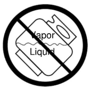
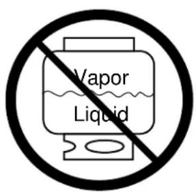
DO NOT obstruct the flow of combustion air and ventilation air to the grill. The propane cylinder must be arranged for vapor withdrawal and equipped with a listed overfilling prevention device. Please use the proper cylinder orientation to provide vapor withdrawal. NOTE: The cylinder must be fully upright for the cylinder to have vapor withdrawal only.
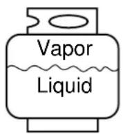
CorrectWrongWrong

CAUTION
a. DO NOT store a spare LP-gas cylinder under or near this appliance.
b. NEVER fill the cylinder beyond 80 percent full.
c. If the information in (a) and (b) is not followed exactly, a fire causing death or serious injury may occur.
NOTE: Other cylinders may be acceptable for use with this appliance provided they are compatible with the appliance nesting hole and retention means. Refer to Step 41 of the Assembly Instructions for correct cylinder to cylinder holder connection.

WARNING
ALL INSTRUCTIONS AND SAFEGUARDS ON THIS PAGE MUST BE FOLLOWED TO PREVENT FIRE, DAMAGE, AND/OR INJURY.
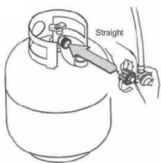
Connecting the LP Tank
- The knob on the LP tank must be closed. Make sure that the knob is turned clockwise to a full stop. The cylinder supply system must be arranged for vapor withdrawal.
- Check that the control knob on the control unit is turned off.
- Remove the protective cap from the LP tank valve and coupling nut.
- Hold the regulator in one hand and insert the nipple into the valve outlet. Be sure the nipple is centered in the valve outlet. The coupling nut connects to the large outside threads on the valve outlet. Use care – do not cross thread the connection.
- Hand-tighten the coupling nut clockwise until it comes to a full stop. Firmly tighten by hand only. Do not use tools.
To Disconnect: Fully close the tank valve by turning clockwise. Turn the coupling nut counterclockwise until the regulator assembly detaches.

WARNING
In the connection process, make sure:
- the regulator inlet connector mates with the cylinder valve outlet properly, safely and firmly, and;
- the LP gas hose does not come in contact or remain in contact with the firebox.
Checking for Leaks
After all connections are made, check all connections and fittings on the LP gas tank valve, gas hose and regulator for leaks with a water and soap solution.
To prevent fire or explosion while testing for a leak:
• Always perform leak test prior to lighting the grill.
- Do not smoke while testing for a leak.
• Always perform leak tests outdoors in a well-ventilated area.
- Do not use any source of flame while testing for leaks.
- Do not use the grill until any and all leaks are corrected.
- If you are unable to correct a leak, disconnect the propane supply and call a gas appliance service dealer.
Perform Leak Test
- Prepare leak test solution by combining 1 part liquid dish soap with 3 parts water. Total solution required is approximately 2 - 3 ounces (70 - 90 ml). Put leak test solution in a spray bottle.
- Ensure all control knobs are in the O "OFF" position.
- Open LP gas tank valve.
- Spray leak test solution on all gas carrying connections and fittings. Presence of bubbles at areas of applied test solution indicates a gas leak. If leaks are detected or you smell or hear gas, shut off the LP gas tank immediately and repair or replace the defective part. Do not use the grill until all leaks are corrected.
CAUTION
Use only the regulator and hose assembly provided. If a replacement is necessary, please call our customer service center. DO NOT use replacement parts that are not intended for this grill.
Before First Use
Remove all hangings or plastic straps, if present.
Before you cook on your new gas grill, it is important to clean your grill with heat. To do this, operate the grill for approximately 15 minutes with the lid closed and all main burner control knobs in the highest position. This will clean the internal parts by burning off any residue and odor from the manufacturing process. NOTE: Burn off is NOT necessary for side burner. Refer to the Operating Instructions on Page 29 for more information.
! CAUTION
If the flame extinguishes accidentally during ignition or operation, immediately TURN OFF the cylinder valve and then TURN OFF the control knobs.
Lighting the Gas Grill

WARNING
Do not lean over grill when lighting. Read instructions before lighting.
- Check that the control knobs are in the O "OFF" position.
- Open valve at tank fully by turning counterclockwise
- Open lid during lighting.
- Push igniter down 3 to 4 seconds while turning desired main control knob to the "HIGH" position. The burner should ignite.
- Repeat for all other burners. If ignition does not take place within 5 seconds, immediately turn the control knob to the O "OFF" position. Wait 5 minutes and repeat step 4 above or refer to match lighting instructions below.
If the burner still does not light, check that there is gas in the cylinder and follow the match lighting instructions.
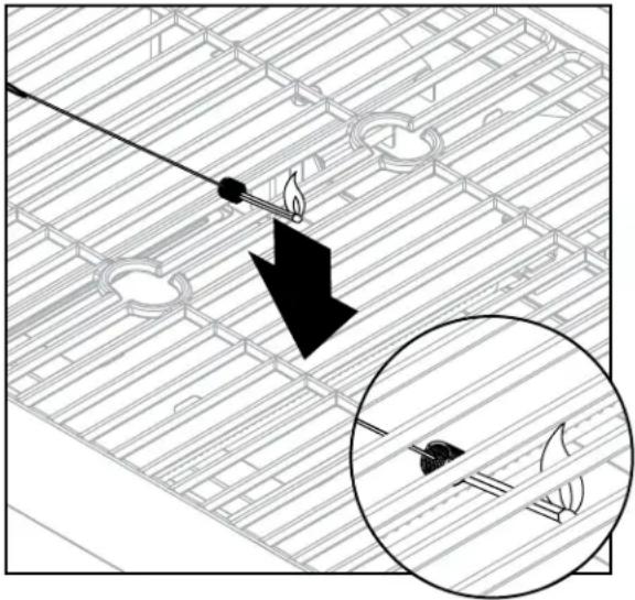
Lighting the Gas Grill with a Match
- Open the lid.
- Insert a match in the end of the match holder that is installed on the right side of the firebox.
- Light the match.
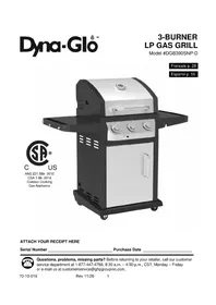
- Immediately place the lit match through the spaces in the grill grates near the ports of the burner between the heat tents as shown. Make sure the lit match is close to the burner ports.
- Press in the control knob that operates the burner and rotate counter-clockwise to "HIGH" position. Burner should light immediately.
- Repeat steps 2 - 5 to light the remaining burners. If burners do not light within 5 seconds, turn all control knobs to the O "OFF" position and wait 5 minutes. Repeat steps 2 - 5 until all burners are lit.
- Adjust burners to desired cooking settings.
natural_image
Diagram showing a fire extinguishing a fire in a building layout, with an inset magnified view of the fire damage (no text or symbols present)Shutdown Instructions
- Turn control knobs clockwise to the O "OFF" position.
- Close valve at tank fully by turning clockwise.
- Close lid.
Turn off LP supply at cylinder when appliance is not in use.
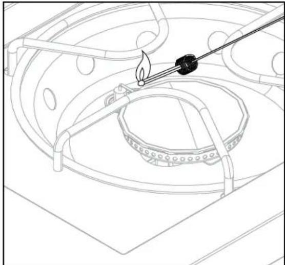
Lighting the Side Burner with a Match
- Insert a match in the end of the match holder that is installed on the right side of the rebox.
- Light the match.
- Immediately place the lit match through the spaces in the grill gates near the ignition wire located next to the burner.
- Press in the control knob that operates the burner and rotate counter-clockwise 🔍 to "HIGH" position. Burner should light immediately. If burner does not light within 5 seconds, turn the control knob to the O "OFF" position and wait 5 minutes. Repeat steps 2 - 4 until the burner is lit.
- Adjust to desired cooking settings.
Using the Grate Hook
Use the grate hook (E) to lift cooking grates.
natural_image
Line drawing of a laboratory setup with a flame being heated by a tool, no text or symbols present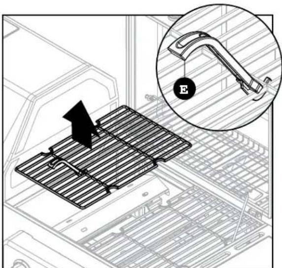
Lighting the Charcoal Grill
This grill has an adjustable charcoal tray. By turning the crank handle, the charcoal tray can be raised or lowered to desired height. This allows for different heat settings depending on the food you are cooking and the temperature you want to cook at. It also allows easy cleaning of the interior of the firebox after the unit has cooled down completely. It is not recommended to raise a fully loaded charcoal tray higher than the middle height setting.
NOTE: The grate is coated with porcelain which is a fragile coating. Handle with care to avoid damage. Do not cool the grate in cold water while it is still hot or the coating may crack. Let the grate cool off by itself.
! DANGER
CARBON MONOXIDE HAZARD
Burning charcoal inside can kill you. It gives off carbon monoxide, which has no odor. NEVER burn charcoal inside homes, vehicles, or tents.
Charcoal Lighting Instructions
- Open grill top.
- Remove cooking grates with grate hooks. Refer to the grate hook instructions on the previous page.
- Adjust charcoal tray to the center position.
- Place one even row of charcoal briquettes in the charcoal tray. Make sure that charcoal does not go above the top of the tray.
- Light briquettes.
- Move charcoal tray to the bottom position.
- With the top open, allow the briquettes to fully ignite (to the point where there is no further flame).
- Once the briquettes are lit, put the grates back in the grill using grate hook and heat resistant gloves.
- Adjust charcoal tray as required to achieve the proper temperature.
- The air vent on the charcoal access door should be kept open during cooking to allow air flow.
You can begin cooking when briquettes have a light coating of grey ash (approx. 25-30 minutes).
Adjusting Temperature
For maximum heat/temperature, open the air vent on the charcoal access door, as well as the smoke stack as required. To reduce the heat/temperature, close the air vents on the charcoal access door or smoke stack as required
NOTE: The temperature should not go above 500^ F ( 260^ C). If the temperature goes above 500^ F ( 260^ C), you should reduce the quantity of briquettes that you have placed in the charcoal tray. The proper cooking temperature should not exceed 500^ F ( 260^ C). Remember to reduce the amount of charcoal next time the grill is used. No more than 3 lbs. (1.36 kgs), or approximately 45 briquettes, should be used.
Seasoning Unit – Gas & Charcoal
- Before your first cooking you should season the unit to enhance the cooking and to provide better overall durability. Failure to properly follow these steps may damage the finish and/or impart metallic flavors to your foods.
- Remove all retail hangtags that are on the unit, making sure NOT to remove safety markings from the unit.
- Coat interior surfaces of grill only with vegetable cooking oil.
- CHARCOAL SIDE: Before first grilling with with charcoal, place an even row of briquettes in the charcoal tray. Do not place any briquettes against walls of the tray.
- Light briquettes and set charcoal tray at medium height by cranking the crank handle.
- Sustain burn for about two hours with lid closed and all dampers to 1/4 open. Allow the unit to cool down properly.
- GAS SIDE: Operate the grill for approximately 15 minutes with the lid closed and the control knob in the highest position. Refer to the lighting instructions on Page 26 for more information.
- Once these steps are completed, the unit is ready for use.
Rust can appear on the inside of your grill. Maintaining a light coating of vegetable oil on interior surfaces will aid in the protection of your grill. Exterior surfaces of the grill may need occasional touch up. We recommend the use of commercially available black high temperature spray paint. NEVER PAINT THE INTERIOR OF THE UNIT!
! WARNING
BURN HAZARD
These metal parts could be very hot while grilling. Always operate these parts while wearing a heat-resistant glove. Never use charcoal starter fluid, gasoline, kerosene or alcohol with an electric ignition.
Grilling with Charcoal
Charcoal is recommended, however wood or a combination of both may be used as the fuel source for grilling if the fuel source is placed and ignited on the charcoal tray. Do not build too large of a fire. We recommend starting a fire with no more than 3 lbs. of charcoal (approximately 45 briquettes) and adding more as needed during cooking. After allowing the fire to burn down, place the cooking grates in the unit. Failure to read and follow instructions for lighting charcoal may result in serious personal injury and or property damage.
Cooking Grates
The best time to "burn off" the cooking grates is after every use (approx. 15 minutes). The grill is already hot from cooking thus requiring less fuel to obtain necessary temperature for "burn off".
To "burn off" or heat clean your grill, turn the burners to the highest position and run for 15 minutes with the lid closed. Then turn off the burners and use a wire brush to clean excess food residue from the grates. Repeat this process for the charcoal grates just prior to cooking or immediately after cooking with charcoal is complete. If cleaning prior to cooking, allow at least 20 minutes after the charcoals have been lit. Use heat-resistant gloves when cleaning the gas and charcoal grates.
NOTE: "Burn off" is not necessary for side burner.
The porcelain grates have an enamel finish (similar to glass) and should be handled with care not to chip.

CAUTION
BURN HAZARD
Ensure the grill is cool before cleaning and conducting maintenance. Ensure the gas supply is turned off at the LP cylinder.
The electronic ignition requires one "AA" alkaline battery, which is included.

WARNING
BURN HAZARD
DO NOT mix old and new batteries.
DO NOT mix alkaline, standard (Carbon-Zinc), or rechargeable (Nickle-Cadmium) batteries.
DO NOT dispose of batteries in fire. Improper disposal may cause batteries to leak or explode.
Recommended Cleaning Supplies
Mild liquid dish soap, warm water, nylon cleaning pad, and a wire brush.
DO NOT use cleaners that contain acid, mineral spirits or any abrasive substance.
Outside Surfaces
It is recommended to use only mild dish soap and hot water to clean grill and grill parts. Rinse with water.
Inside Bottom Pan of Grill Body
To avoid flare-ups, the bottom pan of the cooking box should be kept clean on a regular basis.
Remove residue using a brush, scraper and/or cleaning pad. Wash with mild soap and warm water.
Rinse with warm water. Avoid water splashing into venturi tubes of burners.
Heat Tents
Clean residue with wire brush and wash with mild dish soap and warm water. Rinse with warm water.
Grease Cup
Empty the grease cup and clean with mild dish soap and warm water on a regular basis.
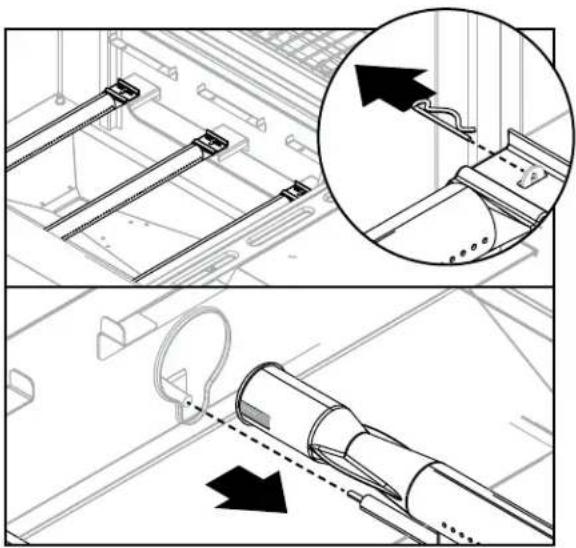
Removing the Burner Assembly
- Make sure all control knobs are in the O OFF position, LP tank valve is closed, and tank is disconnected from regulator and removed from grill.
- Open lid and remove cooking grates and heat tents.
- Remove locking pins at back of burner to detach burners from brackets.
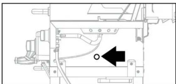
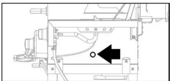
- Detach ignition wire from ignition electrodes, as shown.
- Slide burners out of firebox as shown.
Cleaning the Burner Assembly
- Ensure all burner ports are clear of clogs. Use of a pin or paper clip works well.
- Ensure burner is free of any damage. If damage is found, replace with new burner.
- Ensure the end of the burner and primary air screen are clear from insect nests, dirt or debris.
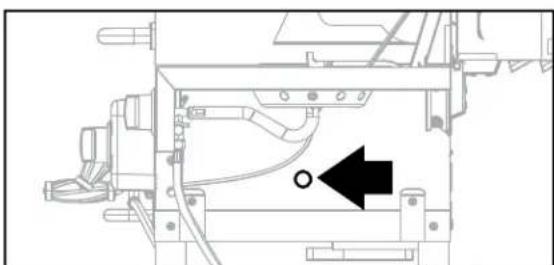
Re-Installing the Burner Assembly
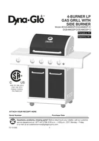
- Ensure that gas valve orifices are correctly positioned inside burner inlet (venturi).
- The use of a flashlight may be necessary to ensure the correct position.
- It is recommended to view the correct position through the bottom of the control panel as illustrated.

WARNING: IT IS VERY IMPORTANT TO CHECK AND ENSURE THAT ALL BURNERS ARE FULLY ENGAGED WITH THE ADJACENT VALVE ORIFICE BEFORE REPLACING THE BURNERS. FAILURE TO DO SO MAY RESULT IN FIRE OR EXPLOSION, POSSIBLY CAUSING SERIOUS INJURY OR DEATH. REFER TO FIGURE 1A FOR PROPER BURNER-TO-VALVE ENGAGEMENT.
Check the Flame in the Firebox
To check the flame, view the flame through the holes in the right side of the firebox.
For maximum fuel efficiency and cooking performance, flame should be a blue-yellow color and be between 1 - 2 inches (2.5 cm - 5 cm) high.
natural_image
Technical diagram showing mechanical assembly steps with magnified detail (no text or symbols)
natural_image
Technical line drawing of a mechanical assembly with no visible text or symbols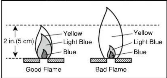
Other Care and Maintenance
- It is recommended that inspection and service on this appliance be conducted annually by a qualified service person.
- It is recommended that you regularly check that the outdoor cooking appliance area is clear and free from combustible material, gasoline and other flammable vapors and liquids.
- It is recommended that you regularly check that the flow of combustion and ventilation air is not obstructed.
- It is recommended that you regularly check that the ventilation openings of the cylinder enclosure (cabinet) are free and clear from debris.
- It is recommended that you regularly check and clean the burner/venturi tubes for insects and insect nests. A clogged tube can lead to a fire beneath the grill.
| PROBLEM POSSIBLE CAUSE CORRECTIVE ACTION | ||
| No gas flow or an obstructed gas flow. | Tank valve not on or fully opened.Empty tank.Poor connection between valve regulator and LP cylinder coupling.Burner inlet blocked. | Fully open tank valve by turning counterclockwise.Check fuel level and replace fuel if necessary.Turn off grill knobs, close the LP cylinder value at top of cylinder and check the connection between the regulator valve and cylinder coupling. Disconnect and reconnect, if necessary.Clean the burner inlet (venturi) and burner as described by the Care and Maintenance section in the manual. |
| The burner will not light using the ignitor procedure (weak or no spark being generated). | The ignition electrode may be covered with grease or residue.The ignition electrode may have a loose or disconnected wire.Cracked or broken ignition electrode.Dead battery or faulty battery connection. | Turn control knobs to the off position and clean the ignition electrode with rubbing alcohol and cotton swab.Check the connection and reconnect any loose or disconnected wires.Replace ignition electrode (see Replacement Parts List).Perform any of the following:a. Replace battery.b. Check to see if battery is inserted correctly.c. Check for any corrosion around battery terminals.d. Check wire connections as stated above. |
| The burner will not light with a match. | Match not reaching burners (when holding match with hand).Empty tank.Poor connection between valve regulator and LP cylinder coupling.Burner inlet blocked. | Use match holder found in cabinet door.Check fuel level and refill tank if necessary.Turn off grill knobs, close the LP cylinder value at top of cylinder and check the connection between the regulator valve and cylinder coupling. Disconnect and reconnect, if necessary.Clean the burner inlet (venturi) and burner as described by the Care and Maintenance section in the manual. |
| Low heat. The LP-gas regulator is equipped with an excess flow device that allows sufficient gas to the burners under normal circumstances. Rapid changes in pressure can trigger this device and prevent all but minimal flow of gas to the burner, causing a low flame and low heat output. This is typically caused by the LP-gas cylinder valve being turned open when one or more burner valves (control knobs) is in the open position causing a surge of pressure that activates the excess flow device. | Follow these steps:1. Close the LP-gas cylinder valve on the top of the cylinder.2. Make sure the burner valves are in the “OFF” position.3. Slowly open the LP-gas cylinder valve and wait 10 seconds.4. Follow the lighting instructions. | |
| Excessive flare-ups. | Grease and/or residue build-up on heat tents or in firebox.Excessive dripping of fat or marinade from food.Cooking temperature too high. | Clean the grill components.Trim the fat from meat and use non-oil based marinades.Lower temperature accordingly. |
1-Year Limited Warranty
This Dual Fuel Grill is warranted for 1 year (5 years on the stainless steel burners) against broken or damaged parts at the time of purchase. It is warranted to be free of defects. Paint is warranted to be free of defects except for rust, which may appear after repeated use.
This warranty does not cover damage or issues related to neglect, abuse or modifications to the appliance. Repair labor is not covered.
All parts that meet the warranty requirements will be shipped at no charge via the discretion of GHP Group Inc. (ground shipments, US Mail or Parcel Post ONLY). Any special handling charges (i.e. Second Day, Overnight, etc.) will be the responsibility of the consumer.
All warranty claims apply only to the original purchaser and require a proof of purchase verifying purchase date. Do not return parts without first obtaining a return authorization number from our customer service department. This service is available by calling toll free 1-877-447-4768, 8:30 a.m. – 4:30 p.m. CST, Monday – Friday.
NOTICE: Some states do not allow the exclusion or limitation of incidental or consequential damages or limitations on how long an implied warranty lasts, so the above limitations or exclusions may not apply to you. This warranty gives you specific legal rights, and you may have other rights that vary from state to state.
Manufactured by:
GHP Group Inc.
8280 Austin Ave.
Morton Grove, IL
60053-3207
Item Name: Dual Fuel Gas/Charcoal Barbeque
Model #: DGJ810CSB-D
Rated Main Burner BTU: 36,000 BTU/Hr
Rated Side Burner BTU: 12,000 BTU/Hr
Item #: 0000000
Product Dimensions Assembled: 27.56 in. L x 73.35 in. W x 50.55 in. H
(70 cm L x 186.3 cm W x 128.4 cm H)
Product Weight: 128 lbs. (58 kgs)
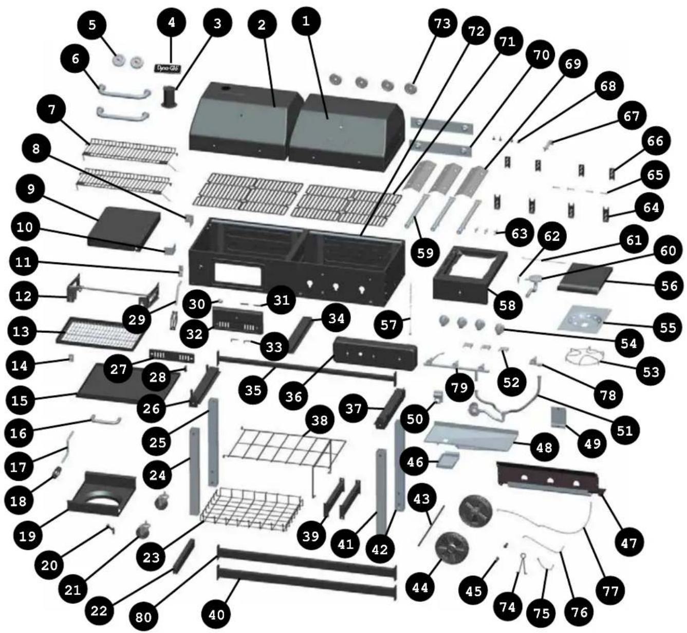
For replacement parts, call our customer service department at 1-877-447-4768, 8:30 a.m. – 4:30 p.m. CST, Monday – Friday.
| PART DESCRIPTION PART # | ||
| N/A | Hardware pack | 413-03023-00 |
| N/A | Owner's/instruction manual | 70-10-0?? |
| 1 | Gas lid assembly WITHOUT handle, temperature gauge, temperature bezel | 413-03002-01 |
| 2 | Charcoal lid assembly WITHOUT handle, temperature gauge, temperature bezel, smoke stack, DynaGlo badge. | 413-03003-01 |
| 3 | Smoke stack assembly | 403-01002-05 |
| 4 | DynaGlo Badge | 213-02002 |
| 5 | Temperature gauge & nut | 213-02005 |
| 6 | Lid handle* | 413-03002-02 |
| 7 | Warming rack with supports | 413-11002-00 |
| 8 | Left table support-rear | 312-02008-02 |
| 9 | Left table | 413-02008-02 |
| 10 | Left table support-front | 312-02008-01 |
| 11 | Charcoal door latch | 413-02003-05 |
| 12 | Charcoal tray adjustment arm assembly | 413-01003-04 |
| 13 | Charcoal tray | 413-01003-02 |
| 14 | Threaded mount for charcoal tray adjustment crank | 404-02003-10 |
| 15 | Ash tray | 413-03005-01 |
| 16 | Ash tray handle* | 403-01005-02 |
| 17 | Charcoal tray adjustment crank only | 403-02003-02 |
| 18 | Charcoal tray adjustment crank handle | 403-02003-05 |
| 19 | Bottom shelf | 403-06001-01 |
| 20 | Tank screw | 403-06001-02 |
| 21 | Caster (includes wrench) | 403-01014-02 |
| 22 | Bottom brace-middle | 413-03001-07 |
| 23 | Storage basket | 413-03001-13 |
| 24 | Left leg-front | 413-03001-04 |
| PART DESCRIPTION PART # | ||
| 25 | Left leg-rear | 413-03001-05 |
| 26 | Cart brace assembly-left | 413-03001-06 |
| 27 | Damper | 413-02003-08 |
| 28 | Damper handle | 413-03001-01 |
| 29 | Charcoal door handle | 413-01013-03 |
| 30 | Charcoal door handle bezel* | 413-02003-04 |
| 31 | Charcoal door pin | 413-01013-04 |
| 32 | Charcoal door | 413-01013-01 |
| 33 | Charcoal door lower hinge | 413-01013-02 |
| 34 | Firebox support-middle | 413-03001-12 |
| 35 | Cart brace assembly-rear | 413-03001-08 |
| 36 | Control panel | 403-07001-04 |
| 37 | Cart brace assembly-right | 413-03001-09 |
| 38 | Intermediate shelf | 413-03001-14 |
| 39 | Bottom brace-left & right | 413-03001-10 |
| 40 | Bottom brace-front | 413-03001-11 |
| 41 | Right leg-front | 413-03001-02 |
| 42 | Right leg-rear | 413-03001-03 |
| 43 | Axle | 403-01018-00 |
| 44 | Wheel | 403-01019-00 |
| 45 | Wheel axle sleeve | 403-01021-00 |
| 46 | Grease cup | 403-04000-01 |
| 47 | Tank heat shield | 403-07001-02 |
| 48 | Grease pan assembly | 403-04000-02 |
| 49 | Ignition heat shield | 403-05000-01 |
| 50 | Ignition | 403-05000-02 |
| 51 | Regulator assembly | 403-07001-08 |
| 52 | Burner support | 403-07001-09 |
| 53 | Side burner cooking grate | 403-07002-09 |
| 54 | Knob | 403-07001-07 |
| 55 | Side burner pan | 403-07002-02 |
| 56 | Side burner cover | 403-07002-03 |
| 57 | Match holder | 403-07001-06 |
*Includes hardware
For replacement parts, call our customer service department at 1-877-447-4768, 8:30 a.m. – 4:30 p.m. CST, Monday – Friday.
For replacement parts, call our customer service department at 1-877-447-4768, 8:30 a.m. – 4:30 p.m. CST, Monday – Friday..
| PART DESCRIPTION PART # | ||
| 58 | Right table assembly 403-0 | 7002-01 |
| 59 | Main burner assembly 403- | 07001-10 |
| 60 | Side burner assembly 403- | 07002-04 |
| 61 | Side burner cover axle 403- | 07002-05 |
| 62 | Side burner ignition elec-trode | 403-07002-06 |
| 63 | Main burner ignition elec-trode | 403-07002-07 |
| 64 | Lower lid hinge 404-03002- | 02 |
| 65 | Lid pin with locking pin 404- | 03002-03 |
| 66 | Upper lid hinge 404-03002- | 04 |
| 67 | Cooking grate hook 403-07 | 005-02 |
| 68 | Lid bumper 403-01002-07 | |
| 69 | Heat tent 403-07001-03 | |
| PART DESCRIPTION PART # | ||
| 70 | Lid heat shield 403-07004-01 | |
| 71 | Cooking grate 403-07005-01 | |
| 72 | Firebox assembly 403-07001-01 | |
| 73 | Knob bezel 403-07001-05 | |
| 74 | Hose retention wire | 313-01016-02 |
| 75 | Ignition wire----240mm 403-05000-03 | |
| 76 | Ignition wire---- 380mm | 403-05000-04 |
| 77 | Ignition wire---- 760mm | 403-05000-05 |
| 78 | Side valve assembly | 403-07002-08 |
| 79 | Main valve assembly | 403-07001-11 |
| 80 | Bottom brace (with labels) -rear | 413-03001-15 |
*Includes hardware
Printed in China
Dyna-Glo™
ARTICLE #0000000
BARBECUE À DEUX COMBUSTIBLES
MODÈLE #DGJ810CSB-D
natural_image
Technical line drawing of a portable electric grill with wheels and control panel (no text or symbols)
ANS Z21.58b-2012 CSA 1.6b-2012
JOIGNEZ VOTRE REÇU ICI
PIÈCE DESCRIPTION QUANTITÉ


natural_image
Technical diagram showing pipe installation with a black arrow pointing to a cable, plus an inset close-up of the cable (no text or symbols)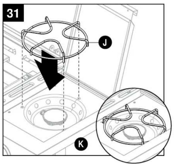

natural_image
Diagram showing a fire extinguisher on a roof structure with an inset magnified view of the damage (no text or symbols)natural_image
Line drawing of a laboratory setup with a flame and a tool, no text or symbols present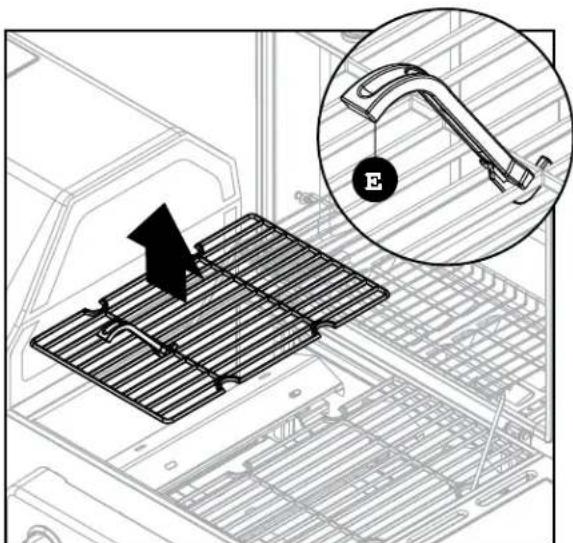
natural_image
Technical diagram showing mechanical assembly steps with magnified detail (no text or symbols)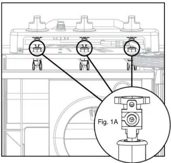
natural_image
Technical line drawing of a mechanical assembly with no visible text or symbols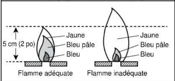
MODELO # DGJ810CSB-D

natural_image
Technical line drawing of a portable electric stove with wheels and internal components (no text or symbols)
C US
ANS Z21.58b-2012
CSA 1.6b-2012
ADJUNTE SU RECIBO AQUÍ


natural_image
Simple line drawing of a mechanical part with a flanged end and a circular hole (no text or symbols)x 4

Pasador de fijación
× 4
natural_image
Technical diagram showing pipe installation with a black arrow pointing to a cable, plus an inset close-up of the cable (no text or symbols)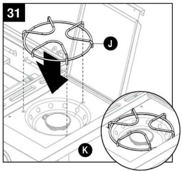
natural_image
Architectural floor plan with fire extinguisher and magnified detail showing structural details (no text or symbols)natural_image
Line drawing of a laboratory setup with a flame inside a chamber and a tool inserted into it (no text or symbols)natural_image
Technical diagram showing mechanical assembly steps with magnified detail (no text or symbols)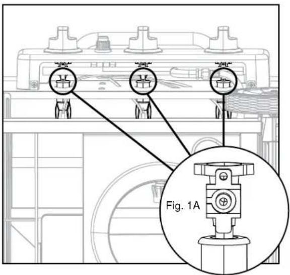
natural_image
Technical line drawing of a mechanical assembly with no visible text or symbols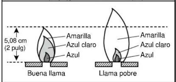
Modelo #: DGJ810CSB-D
Índice de BTU del quemador principal: 36.000 BTU/Hr
Índice de BTU del quemador lateral: 12.000 BTU/Hr
Artículo #: 0000000