DGB390SNPD - Barbecue Dyna-Glo - Free user manual and instructions
Find the device manual for free DGB390SNPD Dyna-Glo in PDF.
| Brand | Dyna-Glo |
| Model | DGB390SNPD |
| Product Type | Propane Gas BBQ |
| Number of Burners | 3 |
| Total Power | 36 000 BTU/h |
| Fuel | Propane (LPG) - 9.07 kg (20 lb) tank |
| Ignition | Electronic by AA battery (included) |
| Cooking Grid Material | Porcelain-enameled steel |
| Cooking Surface | 2 cooking grids + 1 warming rack |
| Additional Features | Side tables, towel bar, tool hook, temperature gauge |
| Grease Management System | Removable grease tray and cup |
| Cart | With wheels (2 fixed + 1 swivel + 1 locking swivel) |
| Dimensions (approx.) | Height 115 cm, Width 130 cm, Depth 60 cm |
| Weight (approx.) | 45 kg |
| Warranty | 1-year limited (parts) |
| Safety Standards | ANSI Z21.58b-2012, CSA 1.6b-2012 |
| Usage | Outdoor use only |
| Assembly | Requires 2 people, about 50 minutes |
Frequently Asked Questions - DGB390SNPD Dyna-Glo
User questions about DGB390SNPD Dyna-Glo
0 question about this device. Answer the ones you know or ask your own.
Ask a new question about this device
Download the instructions for your Barbecue in PDF format for free! Find your manual DGB390SNPD - Dyna-Glo and take your electronic device back in hand. On this page are published all the documents necessary for the use of your device. DGB390SNPD by Dyna-Glo.
USER MANUAL DGB390SNPD Dyna-Glo
ATTACH YOUR RECEIPT HERE
Serial Number
Purchase Date

Questions, problems, missing parts? Before returning to your retailer, call our customer service department at 1-877-447-4768, 8:30 a.m. – 4:30 p.m., CST, Monday – Friday or e-mail us at customerservice@ghpgroupinc.com.
TABLE OF CONTENTS
Safety Information 3
Package Contents 5
Hardware Contents 6
Preparation 6
Assembly Instructions 7
Operation Instructions 13
Care and Maintenance 16
Troubleshooting 19
Warranty 21
Replacement Parts List 22
Assembler/Installer: This manual contains important information necessary for the proper assembly and safe use of this appliance. Read and follow all warnings and instructions before assembling and using this appliance. Leave these instructions with the consumer.
Consumer/User: Follow all warnings and instructions when using this appliance. Retain these instructions for future reference.

If you smell gas:
- Shut off gas to the appliance.
- Extinguish any open flame.
- Open lid.
- If odor continues, keep away from the appliance and immediately call your gas supplier or your local fire department.

WARNING:DANGER:
- Do not store or use gasoline or other flammable liquids or vapors in the vicinity of this or any other appliance.
- An LP (liquid propane) cylinder not connected for use shall not be stored in the vicinity of this or any other appliance.
- This grill is for outdoor use only and shall not be used in a building, garage, under overhangs or any other enclosed area.
- Do not leave a lit grill unattended. Keep children and pets away from the grill at all times.
Please read and understand this entire manual before attempting to assemble, operate or install the product. If you have any questions regarding the product, please call customer service at: 1-877-447-4768, 8:30 a.m. – 4:30 p.m., CST, Monday – Friday.
! DANGER
- Do not use in an explosive atmosphere. Keep grill area clear and free from combustible materials, gasoline and other flammable vapors and liquids.
CALIFORNIA PROPOSITION 65
Fuels used in gas or oil fired appliances and the products of combustion of such fuels contain chemicals known to the State of California to cause cancer, birth defects or other reproductive harm. This product contains chemicals, including lead and lead compounds, known to the State of California to cause cancer, birth defects or other reproductive harm. Wash hands after handling.
CAUTION
- Never use charcoal or lighter fluid with the grill.
- Do not use gasoline, kerosene or alcohol for lighting.
- The LP gas cylinder used with this appliance must be:
(a) Constructed and marked in accordance with the Specifications for LP-Gas Cylinders of the U.S. Department of Transportation (D.O.T.) or the National Standard of Canada, CAN/CSA-B339, Cylinders, Spheres and Tubes for Transportation of Dangerous Goods; and Commission, as applicable; and
(b) Provided with a listed overfilling prevention device.
(c) Provided with a cylinder connection device compatible with the connector for outdoor cooking appliances. This grill is not intended to be used in or installed on recreational vehicles and/or boats.
- Never keep a filled container in a hot car or car trunk. Heat will cause the gas pressure to increase, which may open the relief valve and allow gas to escape.
• Always open grill lid slowly and carefully as heat and steam trapped within the grill can burn you severely.
WARNING
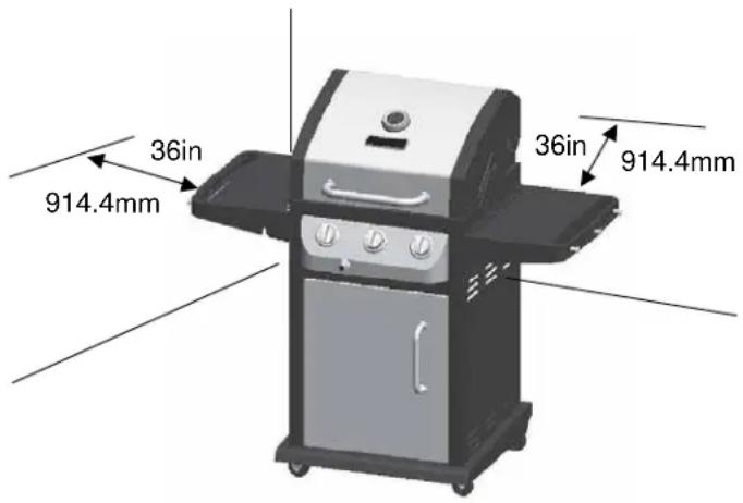
- Do not place the grill under overhead combustible construction or awnings. Minimum clearance from sides and back of unit to combustible construction, 36 inches (914.4mm) from sides and back.
NOTE: The installation must conform with local codes or, in the absence of local codes, with either the National Fuel Gas Code, ANSI Z223.1/NFPA 54, Natural Gas and Propane Installation Code, CSA B149.1, or Propane Storage and Handling Code, B149.2.
CAUTION
- Do not store or use gasoline or other flammable liquids or vapors in the vicinity of this or any other appliance.
- An LP cylinder not connected for use shall not be stored in the vicinity of this or any other appliance.
- This grill is for use with propane gas only (propane cylinder not included).
- Never attempt to attach this grill to the self-contained propane system of a boat, camper trailer, motor home or house.
- Do not attempt to move the grill while it is lit or when it is hot. The casters should be locked when not moving the grill.
- Do not use the grill unless it is completely assembled and all parts are securely fastened and tightened.
- Keep all combustible items and surfaces at least 36 inches (91.44 cm) away from the grill at all times.
- Do not touch metal parts of grill until it has completely cooled (about 45 minutes) to avoid burns, unless you are wearing protective gear (pot holders, gloves, BBQ mittens, etc...).
- Do not alter this grill in any manner.
- Clean and inspect the hose before each use. If there is evidence of abrasion, wear, cuts, or leaks, the hose must be replaced prior to operating the appliance. The replacement hose assembly will be that which is specified by the manufacturer, listed in the repair parts list in this manual.
- Move gas hoses as far away as possible from hot surfaces and dripping hot grease.
- Keep the grill's valve compartment, burners and circulating air passages clean. Inspect the grill before each use. Do not obstruct the flow of gas or ventilation air.
- The use of alcohol, prescription or non-prescription drugs may impair the operator's ability to properly assemble or safely operate the grill.
- Do not leave a lit grill unattended. Keep children and pets away from the grill at all times.
- Do not place this grill on any type of tabletop surface. The grill should be placed on a flat and level surface.
- Do not use the grill in high winds.
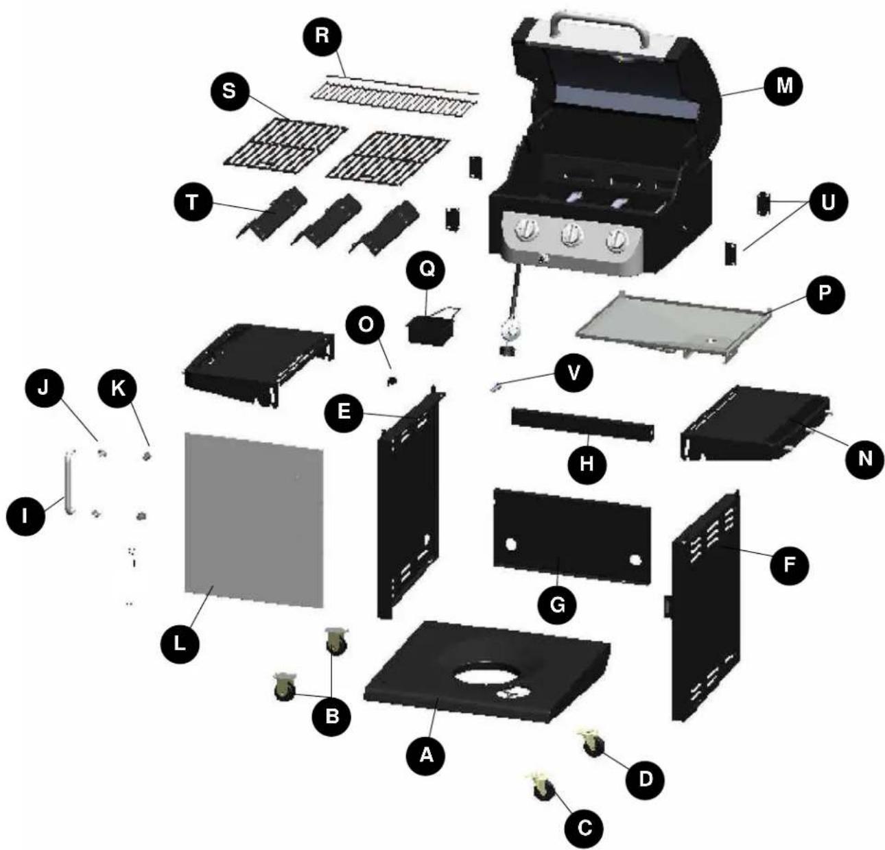
| PART | DESCRIPTION | QUANTITY |
| A | Bottom Shelf 1 | |
| B | Caster 2 | |
| C | Swivel Caster 1 | |
| D | Locking Swivel Caster 1 | |
| E | Cart Left Side Panel 1 | |
| F | Cart Right Side Panel 1 | |
| G | Cart Rear Panel | 1 |
| H | Upper Front Door Brace | 1 |
| I | Door Handle | 1 |
| J | Door Handle Bezel | 2 |
| K | Door Handle Sleeve 2 |
| PART | DESCRIPTION | QUANTITY |
| L | Door Assembly | 1 |
| M | Grill Body | 1 |
| N | Side Table | 2 |
| O | Hose Holder | 1 |
| P | Grease Pan | 1 |
| Q | Grease Cup | 1 |
| R | Warming Rack | 1 |
| S | Cooking Grate | 2 |
| T | Heat Tent | 3 |
| U | Side Table Support | 4 |
| V | AA Battery(1.5v) | 1 |
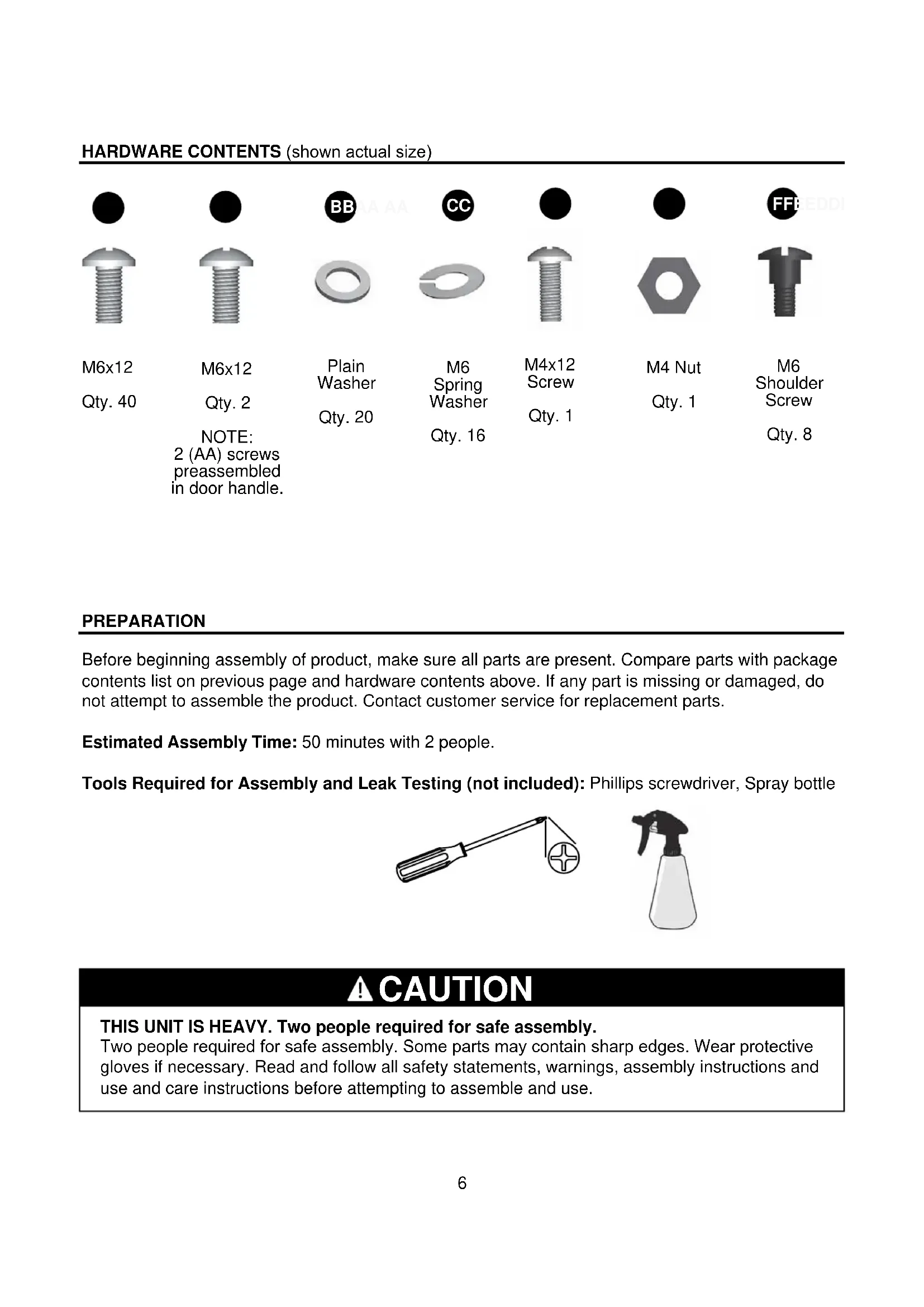
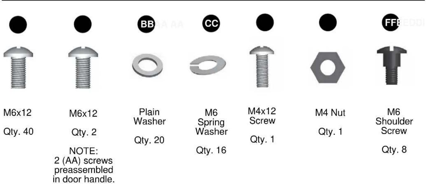
HARDWARE CONTENTS (shown actual size)
PREPARATION
Before beginning assembly of product, make sure all parts are present. Compare parts with package contents list on previous page and hardware contents above. If any part is missing or damaged, do not attempt to assemble the product. Contact customer service for replacement parts.
Estimated Assembly Time: 50 minutes with 2 people.
Tools Required for Assembly and Leak Testing (not included): Phillips screwdriver, Spray bottle
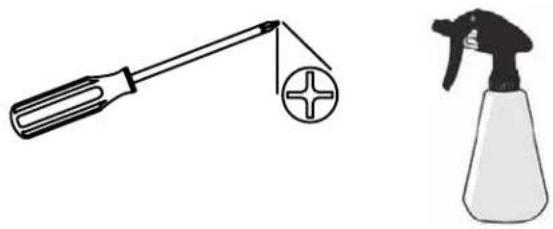
natural_image
Illustration of a screwdriver and a spray can (no text or symbols)CAUTION
THIS UNIT IS HEAVY. Two people required for safe assembly.
Two people required for safe assembly. Some parts may contain sharp edges. Wear protective gloves if necessary. Read and follow all safety statements, warnings, assembly instructions and use and care instructions before attempting to assemble and use.
- Assemble the casters, including 2 direction casters (B), 1 non-locking swivel caster (C), 1 locking swivel caster (D), onto bottom shelf (A) with 4 M6 screw (AA), plain washer (BB) and spring washer (CC).
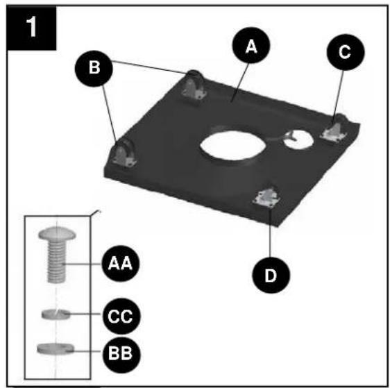
Hardware Used

M6x12 Screw
x 16

Plain Washer
x 16

Spring Washer
x 16
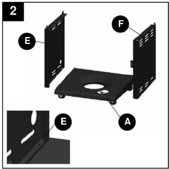
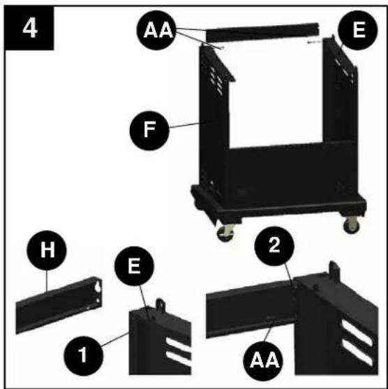
- Insert 4 screws (AA) into holes in bottom shelf (A), leaving 4-6mm clearance from screw head to bottom shelf (A). Attached cart left side panel (E) by placing the panel keyholes over the screw heads (AA) on the left side of bottom shelf (A), slide the cart left side panel (E) so that the screw head is over the smaller part of keyhole. Thread the screw (AA) down snug but do not tighten completely at this step. Repeat with cart right side panel (F).
Hardware Used

M6x12 Screw
x 4
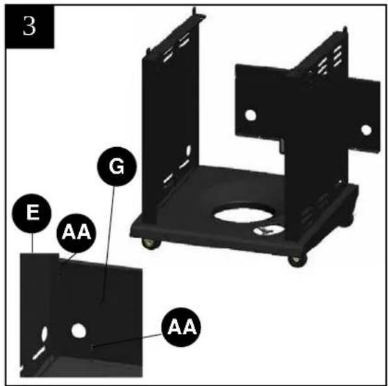
- Insert one screw (AA) into each of the rear holes of the cart left side panel and cart right side panel (E & F), leaving 4-6mm clearance from screw head to the side panels (E & F). Attached the cart rear panel (G) by sliding the keyholes in the cart rear panel over the inserted screws and then push with force. Secure the cart rear panel (G) to the bottom shelf (A) with 2 screws (AA). Tighten the 2 screws on the side panels (E & F).
Hardware Used

M6x12 Screw
x 4
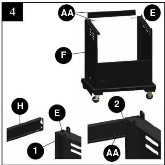
- Insert 2 screws (AA) into upper front holes (labeled 1) in cart left side panel and right side panel (E & F), leaving 4-6mm clearance from screw head to left and right side panel (E & F). Attach the upper front door brace (H) with the larger hole in the upper front door brace (H), slide the upper front door brace (H) so that the screw head is over the smaller hole. Secure the screws but do not tighten completely. Secure another 2 screws into holes (labeled 2).
Hardware Used

M6x12 Screw
x 4
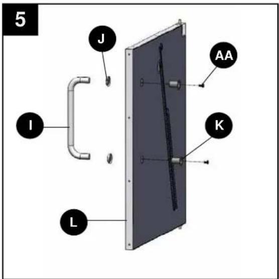
- Remove 2 preassembled screws (AA) and door handle sleeves (K) from the door handle (I). Insert the 2 door sleeves (K) into the holes located on the back of the door assembly (L), insert 2 screws (AA) into the door handle sleeves (K), through the door handle bezels (J) and into the threaded holes in the door handle (I). Tighten using Phillips screwdriver.
Hardware Used

M6x12 Screw
x 2
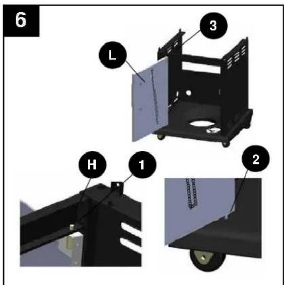
-
Insert the bottom hinge pin (labeled 2) of door assembly (L) into the hole on bottom shelf. Press the hinge pin (labeled 3) on the top of the door assembly by hand and insert into the hole (labeled 1) of upper front brace (H).
-
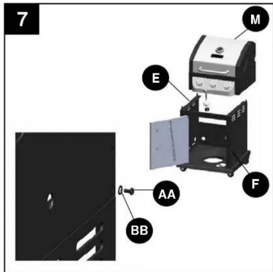
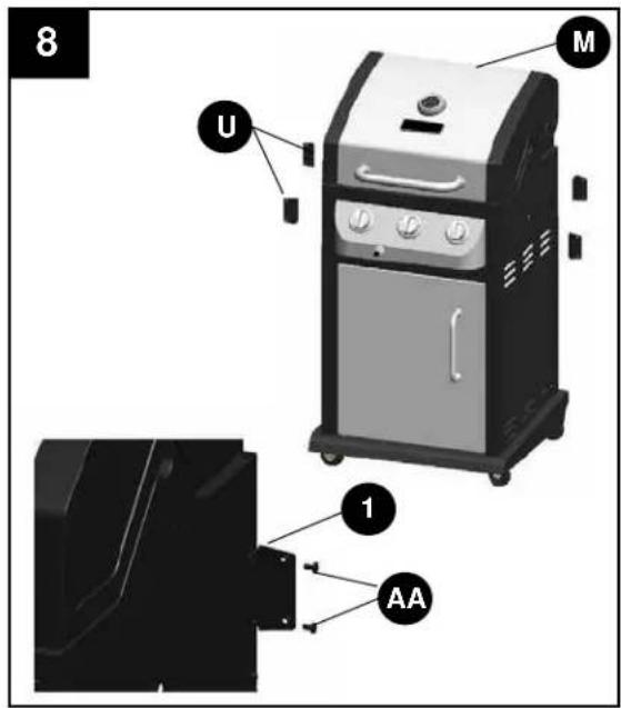
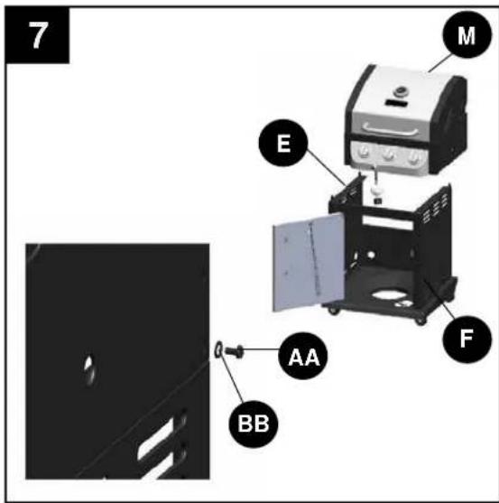
Carefully place the grill body (M) onto the cart left side panel and cart right side panel (E & F). Adjust the grill body (M) so that the holes in the grill body (M) are aligned with the holes in the tabs of the cart side panels (E & F). NOTE: Make sure the gas hose is inside the cart. Fasten the grill body (M) using 2 screws (AA) and plain washer (BB) on each side.
Hardware Used

M6x12 Screw
x 4

M6 Plain Washer
x 4

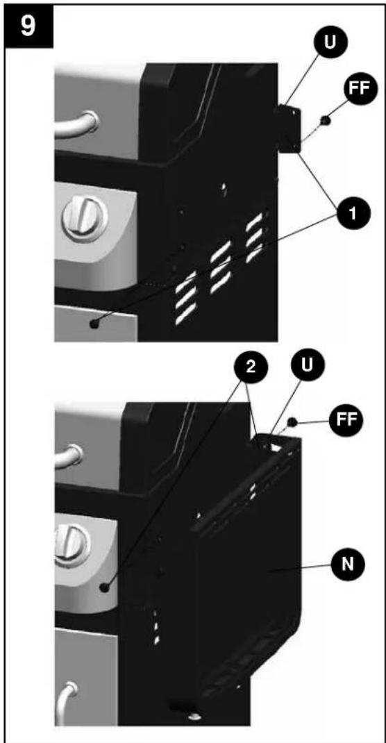
- Install side table supports (U) with 2 M6x12mm (AA) screws into holes (labeled 1) in side of grill body (M) and tighten the screws. Repeat with other side table supports (U).
Hardware Used

M6x12 Screw
× 8
- Secure 2 shoulder screws (FF) into holes (labeled 1) of side table supports (U). Secure side table (N) onto side table support (U) by tightening 2 shoulder screws (FF) into holes (labeled 2). Repeat step with the other side table.
Hardware Used

Shoulder Screw
x 8

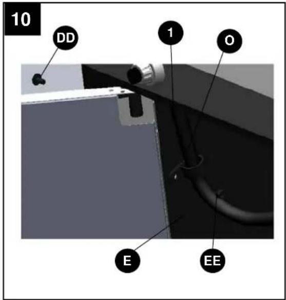
- Secure gas hose and hose holder (O) assembly onto cart left side assembly (E) by tightening 1 M4*12 screw (DD) and 1 M4 nut (EE) into hole (labeled 1) into cart left side table.
NOTE: The gas holder (O) must completely circle the gas hose before securing onto cart left side panel (E) as illustrated below.
Hardware Used

M4x12 Screw
x 1

M4 Nut

x 1
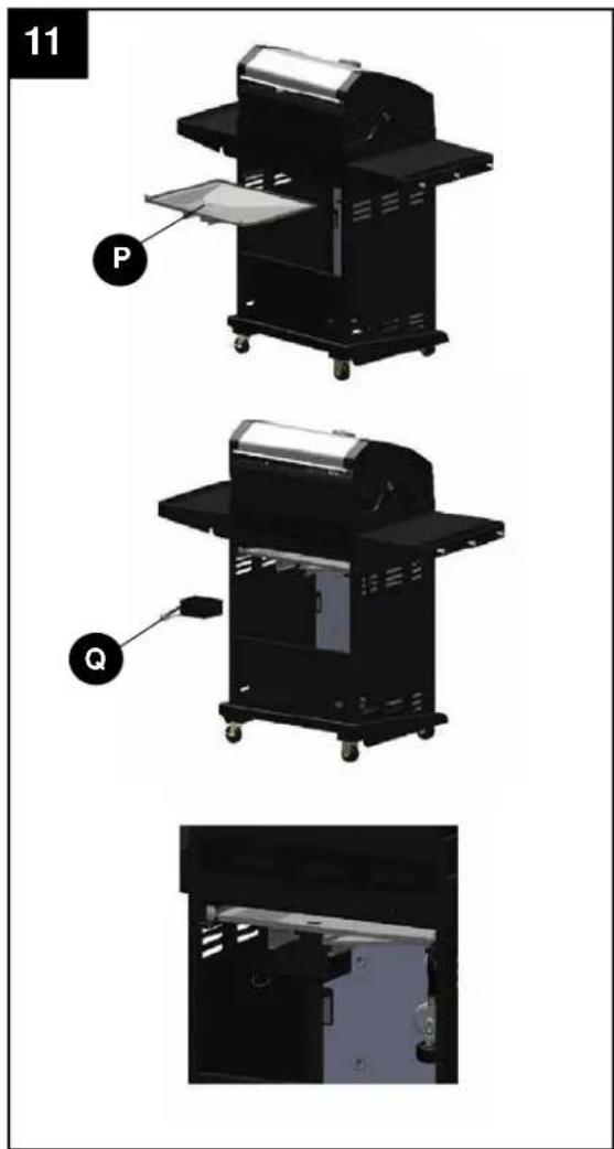
- Insert the grease pan (P) into position by sliding it in the grill body from the rear along the rails located just below the underside of grill body.
NOTE: Grease pan MUST be in position as illustrated below (grease cup support rails on your left while facing the rear of the grill). Insert grease cup (Q) into position by sliding it onto the support rails on the bottom side of grease pan.

WARNING: IT IS VERY IMPORTANT TO CHECK AND ENSURE THAT EACH AND EVERY BURNER IS FULLY ENGAGED WITH THE ADJACENT VALVE ORIFICE BEFORE COMPLETING STEP 12.
FAILURE TO DO SO MAY RESULT IN FIRE OR EXPLOSION, POSSIBLY CAUSING SERIOUS
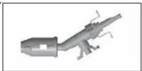
natural_image
3D rendered mechanical component with no visible text or symbolsINJURY OR DEATH. REFER TO MAINTENANCE SECTION INSTRUCTIONS TO PROPERLY CHECK THE ENGAGEMENT.
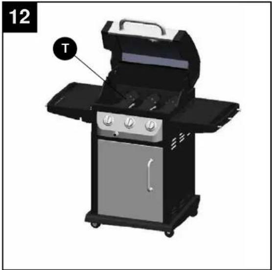
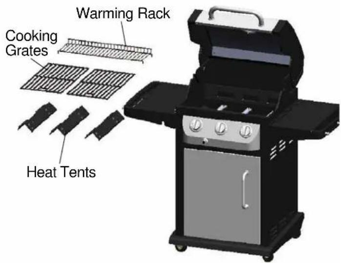
- Place the heat tents (T) into firebox as illustrated.
- Place the cooking grates (S) into grill body (M) as illustrated in the figure. Secure warming rack (R) into grill body (M).
NOTE: Insert the warming rack (R) into the four holes located on both sides of grill body.
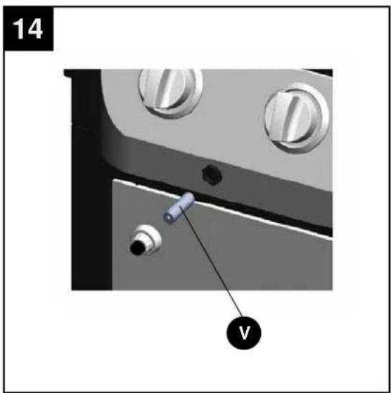
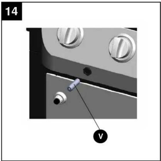
- Unscrew the igniter cap and insert AA battery (V) into the igniter body with positive '+' end facing out. Replace the igniter cap.
natural_image
Exterior view of a gas stove with labeled component 'T' (no text or symbols beyond label)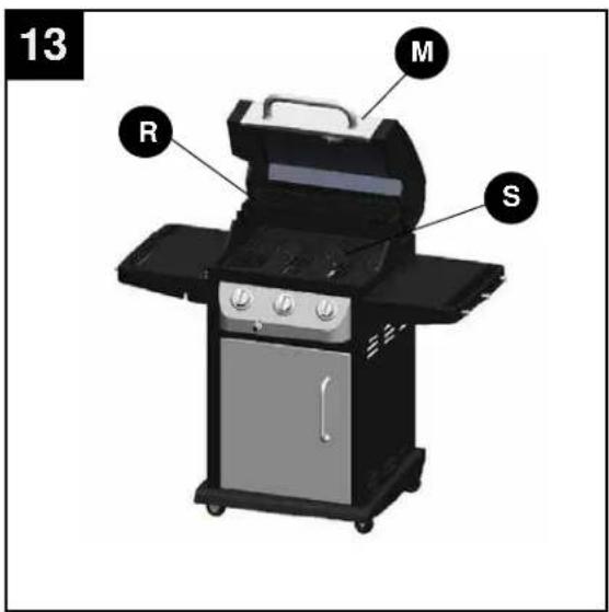
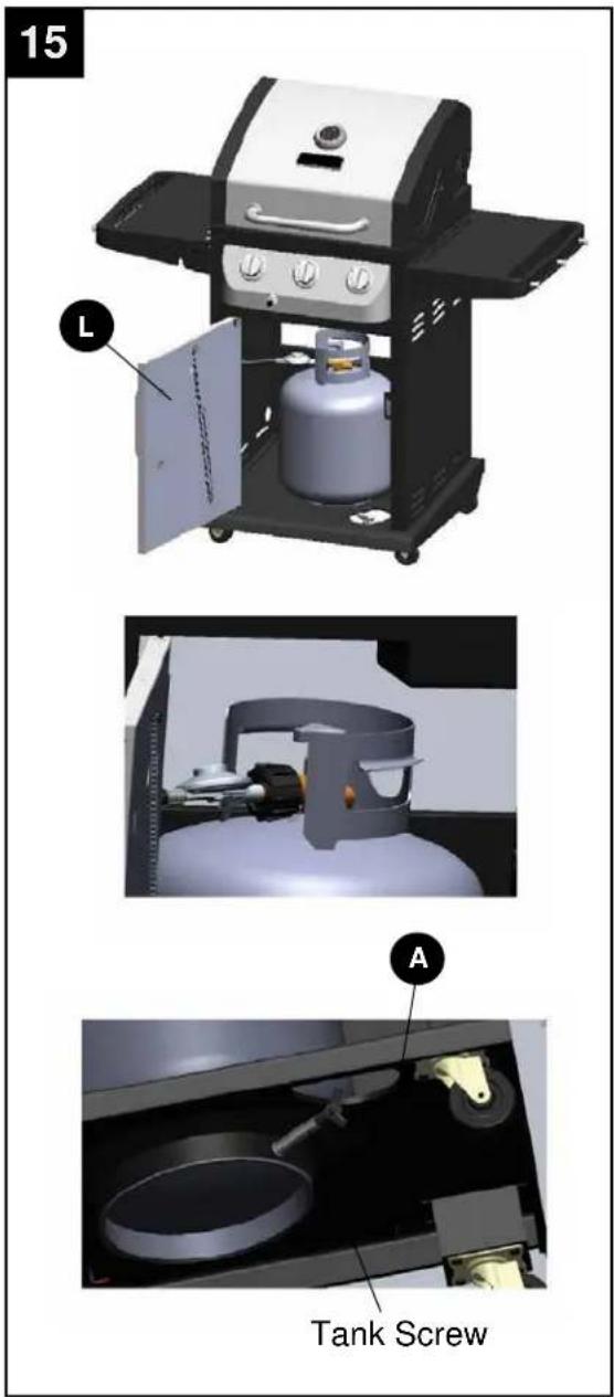
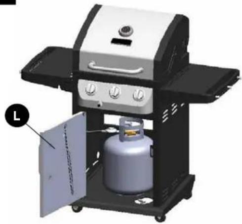
- Open the door assembly (L) and insert the LP gas cylinder (sold separately) into the nesting hole located in the bottom shelf (A). Adjust gas cylinder until positioned correctly (allowing the gas hose to connect to gas cylinder valve). Hand-tighten the hose/regulator coupling to the threaded valve of the LP gas cylinder.
Tighten the tank screw until the cylinder is secured in place inside the nesting hole of the cart.
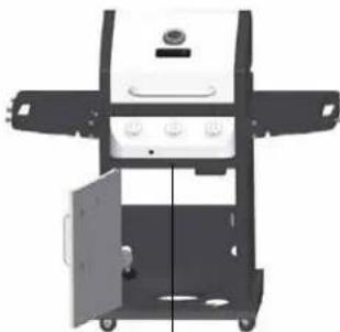
Fully Assembled
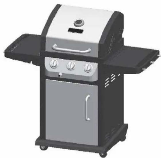
natural_image
Exterior view of a modern electric grill with three speakers and a mounted dish (no text or symbols visible)Front View
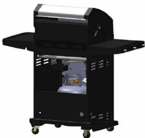
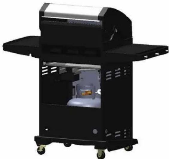
natural_image
3D rendering of a black industrial gas stove with open chamber and wheels (no visible text or symbols)Rear View
CHECKING FOR LEAKS
After all connections are made, check all connections and fittings on the LP gas tank valve, gas hose and regulator for leaks with a water and soap solution.
To prevent fire or explosion while testing for a leak:
• Always perform leak test prior to lighting the grill.
- Do not smoke while testing for a leak.
• Always perform leak tests outdoors in a well-ventilated area.
- Do not use any source of flame while testing for leaks.
- Do not use the grill until any and all leaks are corrected.
- If you are unable to correct a leak, disconnect the propane supply and call a gas appliance service dealer.
PERFORM LEAK TEST
- Prepare leak test solution by combining 1 part liquid dish soap with 3 parts water.
Total solution required is approximately 2 - 3 ounces (70 - 90 ml).
Put leak test solution in a spray bottle. - Ensure all control knobs are in theO OFF position.
- Connect the gas hose to the gas supply.
- Open the LP gas tank valve.
- Spray leak test solution on all gas carrying connections and fittings. Presence of bubbles at areas of applied test solution indicates a gas leak. If leaks are detected or you smell or hear gas, shut off the gas supply valve immediately and repair or replace the defective part. Do not use the grill until all leaks are corrected.
CAUTION
Only use the regulator and hose assembly provided! If a replacement is necessary, please call our customer service center. Do not use replacement parts that are not intended for this grill.
⚠ WARNING
ALL INSTRUCTIONS AND SAFEGUARDS ON THIS PAGE MUST BE FOLLOWED TO PREVENT FIRE, DAMAGE AND/OR INJURY.
CONNECTING GAS CYLINDER
The propane gas supply cylinder to be used must be constructed and marked in accordance with the Specifications for LP Gas Cylinders of the U.S. Department of Transportation (D.O.T.) or the National Standard of Canada, CAN/CSA-B339, Cylinders, Spheres and Tubes for Transportation of Dangerous Goods; and Commission, as applicable; and Provided with a listed overfilling prevention device.
Use only 20-pound cylinders (height: 18.11 inches, tank diameter: 9.84 inches, foot diameter: 8.03 inches) equipped with a cylinder connection device compatible with the connection for outdoor cooking appliances.
The cylinder must include a collar to protect the cylinder valve. The gas cylinder should not be dropped or handled roughly!
If the appliance is not in use, the gas cylinder must be disconnected. Storage of an appliance indoors is permissible ONLY if the cylinder is disconnected and removed from the appliance. Cylinders must be stored outdoors out of the reach of children and must not be stored in a building, garage or any other enclosed area. Your cylinder must never be stored where temperatures can reach over 125^ F.
Place dust cap on cylinder valve outlet whenever the cylinder is not in use. Only install the type of dust cap on the cylinder valve outlet that is provided with the cylinder valve. Other types of caps or plugs may result in leakage of propane.
Before connection, be sure that there is no debris caught in the outlet of the gas cylinder, outlet of the regulator valve or in the outlet of the burner and burner ports. Connect regulator valve and hand-tighten firmly. Keep the propane cylinder valve closed and disconnect the propane cylinder from the regulator valve when the grill is not in use.
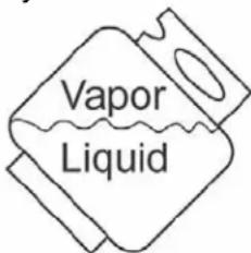
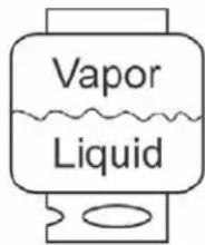
DO NOT obstruct the flow of combustion air and ventilation air to the grill. The propane cylinder must be arranged for vapor withdrawal and equipped with a listed overfilling prevention device. Please use the proper cylinder orientation to provide vapor withdrawal. NOTE: The cylinder must be fully upright for the cylinder to have vapor withdrawal only.
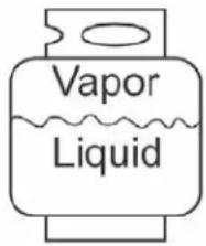
Correct
Wrong
Wrong
⚠️ CAUTION
a. Do not store a spare LP-gas cylinder under or near this appliance.
b. Never fill the cylinder beyond 80 percent full.
c. If the information in (a) and (b) is not followed exactly, a fire causing death or serious injury may occur.
NOTE: Other cylinders may be acceptable for use with this appliance provided they are compatible with the appliance nesting hole and retention means. Refer to Step 15 of the Assembly Instructions for correct cylinder to cylinder holder connection.
⚠ WARNING
ALL INSTRUCTIONS AND SAFEGUARDS ON THIS PAGE MUST BE FOLLOWED TO PREVENT FIRE, DAMAGE AND/OR INJURY.
CONNECTING THE LP TANK
- The knob on the LP tank must be closed. Make sure that the knob is turned clockwise to a full stop. The cylinder supply system must be arranged for vapor withdrawal.
- Check that the control knob on the control unit is turned off.
- Remove the protective cap from the LP tank valve and coupling nut.
- Hold the regulator in one hand and insert the nipple into the valve outlet. Be sure the nipple is centered in the valve outlet. The coupling nut connects to the large outside threads on the valve outlet. Use care – do not cross thread the connection.
- Hand-tighten the coupling nut clockwise until it comes to a full stop. Firmly tighten by hand only. Do not use tools.
To Disconnect: Fully close the tank valve by turning clockwise.
Turn the coupling nut counterclockwise until the regulator assembly detaches.

⚠ WARNING
In the connection process, make sure:
- the regulator inlet connector mates with the cylinder valve outlet properly, safely and firmly, and;
- the LP gas hose does not come in contact or remain in contact with the firebox.
Lighting The Grill
Before first use:
Remove all hangings or plastic straps, if present. Before you cook on your new gas grill, it is important to clean your grill with heat. To do this, operate the grill for approximately 15 minutes with the lid closed and the control knob in the highest position. This will clean the internal parts by burning off any residue and odor from the manufacturing process.
CAUTION
If the flame extinguishes accidentally during ignition or operation, immediately TURN OFF the cylinder valve and then TURN OFF the control knob.
WARNING
Do not lean over grill when lighting. Read instructions before lighting.
- Check that the control knobs are in the ⭕ OFF position.
- Open valve at tank fully by turning counter-clockwise.
- Open lid during lighting.
- Push igniter down 3 to 4 seconds while turning right side control knob to the ⬇ HIGH position. The burner should ignite.
- Repeat for all other burners.
If ignition does not take place within 5 seconds, immediately turn the control knob to the OFF position. Wait 5 minutes and repeat step 4 above or refer to match lighting instructions below.
If the burner still does not light, check that there is gas in the cylinder and follow the match lighting instructions.
LIGHTING THE GRILL WITH A MATCH
- Open the lid
- Insert a match in the end of the match holder that is installed on the inside of the cabinet door.
- Light the match.
- Immediately place the lit match through the spaces in the grill gates near the ports of the burner between the heat tents as shown. Make sure the lit match is close to the burner ports.
- Press in the control knob that operates the burner and rotate counter-clockwise to
High position and burner should light immediately. - Repeat 2\~5 steps to lighting the remaining burners.
- Adjust burners to desired cooking settings.
CAUTION
Make sure all burner controls are off, except for the burner being lit and the burners that have been lit.
natural_image
Close-up of a mechanical component with a metallic handle and internal grooves (no visible text or symbols)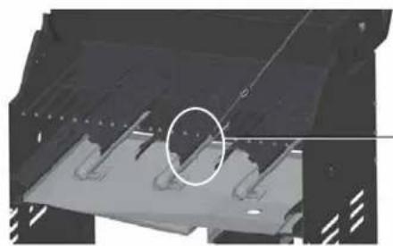
natural_image
Mechanical component with a highlighted circular feature and internal features (no visible text or symbols)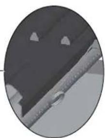
natural_image
Close-up of a dark fabric or metal strip with a small droplet on the edge (no visible text or symbols)SHUTDOWN INSTRUCTIONS
- Turn control knobs clockwise to the OFF position.
- Close valve at tank fully by turning clockwise.
- Close lid.
Turn off LP supply at cylinder when appliance is not in use.
CARE AND MAINTENANCE
Cooking Grates
The best time to 'burn-off' the cooking grates is after every use (approx. 15 minutes). The grill is already hot from cooking thus requiring less fuel to obtain necessary temperature for 'burn-off'.
To 'burn off' or heat clean your grill, turn the burners to highest position and run for 15 minutes with the lid closed. Then turn off the burners and use a wire brush to clean excess food residue from the grates.
The porcelain grates have an enamel finish (similar to glass) and should be handled with care not to chip.
CAUTION
Ensure the grill is cool before cleaning and conducting maintenance and with the gas supply turned off at the LP Gas Cylinder.
Recommended Cleaning Supplies
Mild liquid dish soap, warm water, nylon cleaning pad, wire brush
DO NOT use cleaners that contain acid, mineral spirits or any abrasive substance.
Outside Surfaces
It is recommended to use only mild dish soap and hot water to clean grill and grill parts.
Rinse with warm water.
Inside Bottom Pan of Grill Body
To avoid flare-ups, the bottom pan of the cooking box should be kept clean on a regular basis.
Remove residue using a brush, scraper and/or cleaning pad. Wash with mild dish soap and warm water. Rinse with warm water. Avoid water splashing into venturi tubes of burners.
Heat Tents
Clean residue with wire brush and wash with mild dish soap and warm water. Rinse with warm water.
Grease Cup
Empty the grease cup and clean with mild dish soap and warm water on a regular basis.
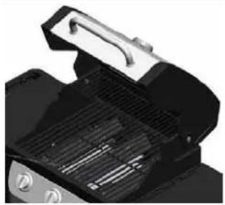
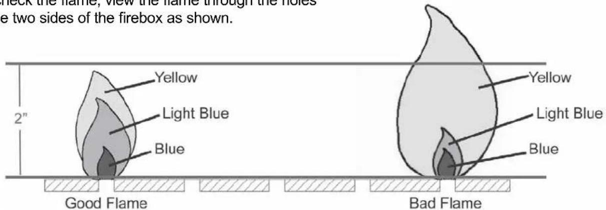
Checking The Flame
For maximum fuel efficiency and cooking performance, flame should be a blue-yellow color and be between 1-2 inches high.
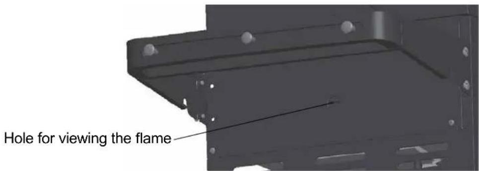
To check the flame, view the flame through the holes in the two sides of the firebox as shown.
Burner Assembly
Removing The Burner Assembly
-
Make sure all control knobs are in the OFF position, gas supply valve is closed, and the gas hose is disconnected from the gas supply.
-
Open lid and remove warming rack, cooking grates, and heat tents.
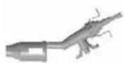
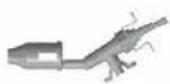
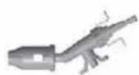
- Remove hinge pin as illustrated in Figure 1. Remove the 2 screws that secure the igniter electrode to the burner as illustrated in Figure 2.
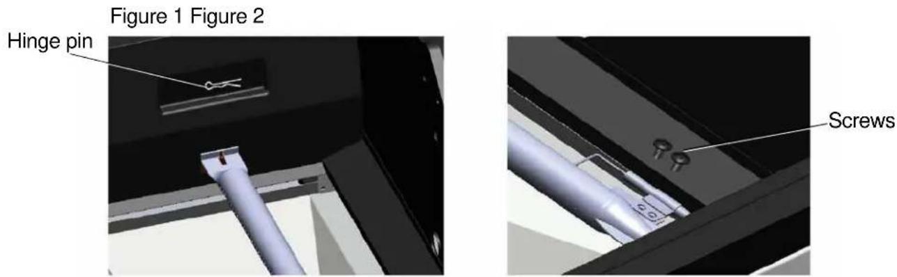
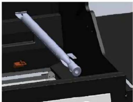
- Slide burners out of firebox as shown.
natural_image
3D rendered mechanical part with a cylindrical shaft and mounting bracket (no visible text or symbols)Cleaning the Burner Assembly
- Make sure the grill is cool
- Ensure all burner ports are clear of clogs. Use of a pin or paper clip works well.
- Ensure burner is free of any damage. If damage is found, replace with new burner.
- Ensure the end of the burner and primary air screen are clear from insect nests, dirt or debris.
Re-installing the Burner
Ensure that gas valve orifices are correctly positioned inside burner inlet (venturi).
The use of a flashlight may be necessary to ensure the correct position.
It is recommended to view the correct position through the bottom of firebox as illustrated below.
natural_image
Exterior view of a portable electric vehicle (no visible text or symbols)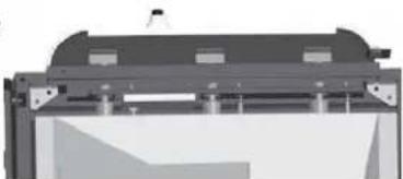
natural_image
Pure mechanical assembly diagram without any text, numbers, or symbolsBottom View
Wrong Wrong Correct
View the correct position from the bottom of the firebox.
⚠ WARNING
If the instructions above are not followed, a fire or explosion may result, possibly causing serious bodily injury or death.
Other Care and Maintenance
It is recommended that inspection and service on this appliance be conducted annually by a qualified service person.
It is recommended that you regularly check that the outdoor cooking appliance area is clear and free from combustible material, gasoline and other flammable vapors and liquids.
It is recommended that you regularly check that the flow of combustion and ventilation air is not obstructed.
It is recommended that you regularly check that the ventilation openings of the grill cabinet are free and clear from debris.
It is recommended that you regularly check and clean the burner/venturi tubes for insects and insect nests. A clogged tube can lead to a fire beneath the grill.
The electronic ignition requires 1 "AA" alkaline battery, which is included.
⚠ WARNING
DO NOT mix old and new batteries.
DO NOT mix alkaline, standard (Carbon-Zinc), or rechargeable (Nickel-Cadmium) batteries.
DO NOT dispose of batteries in fire. Improper disposal may cause batteries to leak or explode.
TROUBLESHOOTING
If you have any questions regarding the product, please call customer service at 1-877-447-4768, 8:30 a.m. – 4:30 p.m., CST, Monday – Friday.
| PROBLEM POSSIBLE CAUSE CORRECTIVE ACTION | ||
| The burner will not light using the ignitor procedure (weak or no spark being generated). | 1. The igniter electrode may be covered with grease or residue.2. The igniter electrode may have a loose or disconnected wire.3. Cracked or broken ignition electrode.4. Dead battery or faulty battery connection. | 1. Clean the ignitor electrode.2. Check the connection and reconnect any loose or disconnected wires.3. Replace ignition electrode (see Replacement Parts List).4. Perform any of the following:a. Replace batteryb. Check to see if battery is inserted correctly.c. Check for any corrosion around battery terminals.d. Check wire connections as stated above |
| Low Heat. | 1. Insufficient gas pressure to the unit. | 1. Call a qualified service agency to check the gas supply pressure and correct the pressure. |
| Excessive Flare Ups. | 1. Grease and/or residue build-up on heat tents or in firebox.2. Excessive dripping of fat or marinade from food.3. Cooking temperature too high. | 1. Clean the grill components.2. Trim the fat from meat and use non-oil based marinades.3. Lower temperature accordingly. |
| The burner will not light with a match. | 1. Match not reaching burners (when holding match with hand).2. Empty tank.3. Poor connection between valve regulator and LP cylinder coupling.4. Burner inlet blocked. | 1. Use match holder found in cabinet door.2. Check fuel level and refill tank if necessary.3. Turn off grill knobs, close the LP cylinder valve at top of cylinder and check the connection between the regulator valve and cylinder coupling.Disconnect and reconnect, if necessary.4. Clean the burner inlet (venturi) and burner as described by the Care and Maintenance section in the manual. |
| No gas flow or an obstructed gas flow. | 1. Tank valve not on or fully opened.2. Empty tank.3. Poor connection between valve regulator and LP cylinder coupling.4. Burner inlet blocked. | 1. Fully open tank valve by turning counterclockwise.2. Check fuel level and replace fuel if necessary.3. Turn off grill knobs, close the LP cylinder valve at top of cylinder and check the connection between the regulator valve and cylinder coupling.Disconnect and reconnect, if necessary.4. Clean the burner inlet (venturi) and burner as described by the Care and Maintenance section in the manual. |
1-Year Limited Warranty
This LP gas grill is warranted for 1 year (5 years on the Stainless Steel burners) against broken or damaged parts at the time of purchase. It is warranted to be free of defects. Paint is warranted to be free of defects except for rust, which may appear after repeated use.
This warranty does not cover damage or issues related to neglect, abuse, or modifications to the appliance. Repair labor is not covered.
All parts that meet the warranty requirements will be shipped at no charge via the discretion of the manufacturer (ground shipments, US Mail, or Parcel Post ONLY). Any special handling charges (i.e. Second Day, overnight, etc.) will be the responsibility of the consumer.
All warranty claims apply only to the original purchaser and require a proof of purchase verifying purchase date. Do not return parts without first obtaining a return authorization number from our customer service. This service is available by calling toll free 1-877-447-4768, 8:30 a.m. – 4:30 p.m., CST, Monday – Friday.
NOTICE: Some states do not allow the exclusion or limitation of incidental or consequential damages or limitations on how long an implied warranty lasts, so the above limitations or exclusions may not apply to you. This warranty gives you specific legal rights and you may also have other legal rights which may vary from state to state.
GHP Group, Inc.
8280 Austin Avenue
Morton Grove, IL, USA
60053-3207
Item Name: 3-Burner LP Gas Grill
Model #: DGB390SNP-D
Rated BTU: 36,000 BTU/Hr
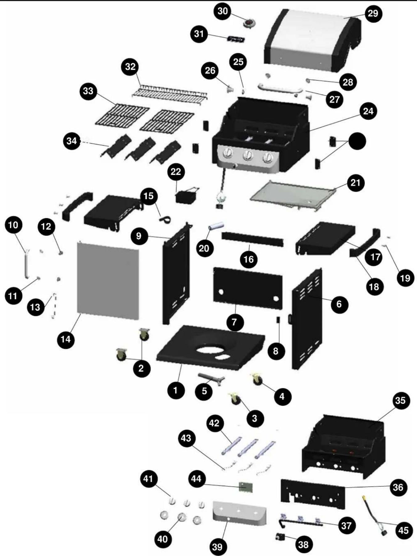
For replacement parts, call our customer service department at 1-877-447-4768, 8:30 a.m. – 4:30 p.m., CST, Monday – Friday.
| PART | DESCRIPTION | |
| 1 | bottom panel | 104 - 04006 |
| 2 | caster - includes 4 screws/flat washers/spring washers | 104 - 04018 |
| 3 | swivel caster - includes 4 screws/flat washers/spring washers | 104 - 04017 |
| 4 | locking swivel caster - includes 4 screws/flat washers/spring washers | 104 - 04019 |
| 5 | LP cylinder retention screw | 104 - 04012 |
| 6 | cart right side panel | 104 - 04010 |
| 7 | cart rear panel | 104 - 04008 |
| 8 | door Magnet | 104 - 14020 |
| 9 | cart side left panel | 104 - 04009 |
| 10 | cart front door handle | 104 - 14021 |
| 11 | door handle bezel | 104 - 14022 |
| 12 | door handle sleeve | 104 - 14023 |
| 13 | match holder | 104 - 14024 |
| 14 | cart front door assembly - no handle | 104 - 04020 |
| 15 | hose holder | 104 - 04007 |
| 16 | cart front upper door brace | 104 - 04011 |
| 17 | side table | 104 - 04001 |
| 18 | towel bar | 104 - 14001 |
| 19 | tool hook | 104 - 14002 |
| 20 | AA battery (1.5V) | 104 - 05002 |
| 21 | grease pan with heat shield | 104 - 04013 |
| 22 | grease cup | 104 - 04014 |
| 23 | side table support | 104 - 04003 |
| 24 | firebox assembly - includes burners/LP gas valve & manifold assembly/LP gas hose & regulator/control panel/ignition wire and electrode. | 104 - 03001 |
| 25 | cap nut (secures lid pivot pin) | 104 - 12001 |
| 26 | lid pivot pin | 104 - 12002 |
| 27 | lid handle | 104 - 12003 |
| 28 | lid handle bezel | 104 - 12004 |
| 29 | grill lid assembly-includes lid bumpers | 104 - 02001 |
| 30 | temperature gauge with nut | 104 - 12005 |
| 31 | badge | 104 - 22006 |
| 32 | warming rack | 104 - 13001 |
| 33 | cooking grate (pack of 1) | 104 - 13002 |
| 34 | heat tent (pack of 1) | 104 - 13003 |
| 35 | firebox assembly - includes lid bumpers | 104 - 13004 |
| 36 | firebox front outer panel | 104 - 13005 |
| 37 | LP gas valve & manifold | 104 - 13006 |
| 38 | electronic ignition housing | 104 - 13007 |
| 39 | control panel | 104 - 13008 |
| 40 | control knob bezel | 104 - 13009 |
| 41 | control knob | 104 - 13010 |
| 42 | main burner- with cotter pin (pack of 1) | 104 - 13011 |
| 43 | ignition electrode and ignition wire assembly | 104 - 13012 |
REPLACEMENT PARTS LIST
| PART | DESCRIPTION | |
| 44 | heat shield for electronic ignition | 104 - 13013 |
| 45 | LP gas hose and regulator assembly | 104 - 13014 |
| n/a | hardware pack | 104 - 05001 |
| n/a | owner's/instruction manual | 70 - 10 - 017 |
Dyna-Glo™
MISE EN GARDE
natural_image
Illustration of a screwdriver and a spray can (no text or symbols)⚠ MISE EN GARDE
CET ARTICLE EST LOURD. DEUX PERSONNES SONT NÉCESSAIRES POUR ASSEMBLER L'ARTICLE EN TOUTE SÉCURITÉ.


! AVERTISSEMENT : IL EST TRÈS IMPORTANT DE S'ASSURER QUE CHACUN DES BRÛLEURS EST COMPLÈTEMENT INSÉRÉ DANS L'ORIFICE DU ROBINET ADJACENT AVANT DE PASSER À L'ÉTAPE 12.
LE NON-RESPECT
DE CETTE CONSIGNE POURRAIT ENTRAÎNER UN INCENDIE OU UNE
natural_image
3D rendered mechanical component with no visible text or symbolsEXPLOSION, CE QUI POURRAIT CAUSER DES BLESSURES GRAVES, VOIRE LA MORT. CONSULTEZ LES INSTRUCTIONS DE LA SECTION ENTRETIEN INDIQUANT LA FAÇON ADÉQUATE DE VÉRIFIER SI LES BRÛLEURS SÔNT INSÉRÉS.
natural_image
Exterior view of a black and silver electric grill with labeled component (T), no visible text or symbols beyond label
natural_image
Close-up of a mechanical component with a metallic handle and ventilation slots (no visible text or symbols)
natural_image
Mechanical component with a highlighted circular feature and internal features (no text or symbols visible)
natural_image
Close-up of a garment collar with measurement markings (no visible text or symbols)INSTRUCTIONS POUR L'ARRÊT
natural_image
3D rendered mechanical part with a cylindrical shaft and mounting bracket (no visible text or symbols)ENTRETIEN
natural_image
Exterior view of a portable electric vehicle chassis with open door and wheels (no text or symbols visible)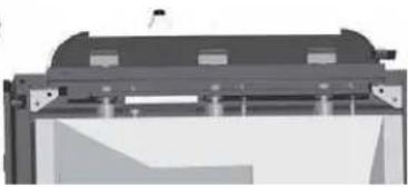
natural_image
Pure mechanical component diagram without any text, numbers, or symbolsVue de dessous
CorrigezMalMal
ADJUNTE SU RECIBO AQUÍ
Número de serie
Fecha de compra

PRECAUCIÓN
other
| Product | Qty | Rating | | --- | --- | --- | | Tornillo M6x12 | 40 | Notable | | Tornillo M6x12 | 40 | Notable | | Arandela lisa | 20 | Notable | | Arandela de Resorte M6 | 16 | Notable | | Tornillo M4x12 Screw | 1 | Notable | | M4 Tuerca | 1 | Notable | | M6 Tornillo para el Soporte Horizontal | 8 | Notable |PREPARACION
natural_image
Illustration of a screwdriver and a spray can (no text or symbols)PRECAUCION
ESTA UNIOAD ES PESADA. SE NECESITAN DOS PERSONAS PARA UN ENSAMBLAJE SEGURO.


ADVERTENCIA: ES MUY IMPORTANTE VERIFICAR Y ASEGURARSE DE QUE TODOS LOS QUEMADORES ESTEN COMPLETAMENTE ACOPLADOS CON EL ORIFICIO DE LA VALVULA
ADYACENTE ANTES DE FINALIZAR EL PASO 12. NO HACERLO PODRIA PROVOCAR UN INCENDIO
natural_image
3D rendered mechanical component with no visible text or symbolsO UNA EXPLOSION, LO QUE POSIBLEMENTE CAUSARiA LESIONES GRAVES 0 LA MUERTE. CONSULTE LAS INSTRUCCIONES DE LA SECCION DE MANTENIMIENTO PARAVERIFICAR CORRECTAMENTE EL ACOPLAMIENTO.
natural_image
Exterior view of a gas stove with open door and control panel (no text or symbols visible)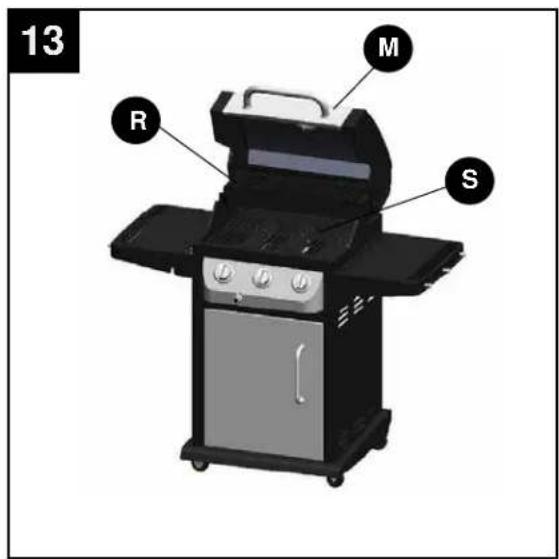

natural_image
Exterior view of a modern electric grill with three speakers and a mounted dish (no text or symbols visible)Vista Frontal
natural_image
3D rendering of a black industrial exhaust gas stove with open chamber and wheels (no visible text or symbols)Vista Trasera
15
natural_image
Exterior view of a gas stove with open doors and internal components (no visible text or symbols)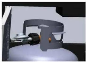
natural_image
3D rendered mechanical component with cylindrical housing and internal components (no visible text or symbols)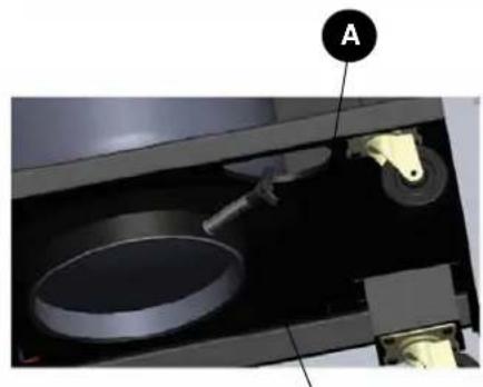
natural_image
Interior view of a mechanical device with labeled component A (no text or symbols beyond label)Tanque Tornillo
BÚSQUEDA DE FUGAS
natural_image
3D rendered mechanical part with a cylindrical shaft and orange connector, no visible text or symbolsModelo #: DGB390SNP-D