
Monicon XL - Audio recorder Palmer - Free user manual and instructions
Find the device manual for free Monicon XL Palmer in PDF.
| Product type | Studio monitor controller (audio recorder) |
| Brand | Palmer |
| Model | Monicon XL |
| Dimensions (W x H x D) | 254 x 84 x 215 mm |
| Weight | 1.49 kg |
| Power supply | External power supply 18 V DC, 1.5 A |
| Number of inputs | 3 stereo inputs (2 balanced 6.35 mm jack, 1 unbalanced RCA + 3.5 mm jack + S/PDIF) |
| Number of outputs | 3 balanced monitor outputs (6.35 mm jack), 2 unbalanced line outputs (MAIN/CUE), 2 headphone outputs |
| Max input level | +20 dBu |
| Max output level | +25 dBu (balanced), +20 dBu (unbalanced) |
| Frequency response | 12 Hz - 90 kHz (-1 dB) |
| Total harmonic distortion (THD) | 0.002% (BW 20 - 20,000 Hz) |
| Signal-to-noise ratio (SNR) | 102 dB (A-weighted) @ +4 dBu |
| Dynamic range (DR AES17) | 115 dB |
| Talkback microphone | Built-in, electret condenser, adjustable volume |
| Displays | 8-segment LED level with Peak-Hold, 7-segment LED correlation |
| Housing material | Metal / MDF |
| Color | Black |
| Included accessories | External power supply, instruction manual |
| Care and cleaning | Use a dry cloth |
| Safety | Do not open the device, avoid water and flammable objects |
| Warranty and repairability | See manufacturer's conditions on the Adam Hall website |
Frequently Asked Questions - Monicon XL Palmer
User questions about Monicon XL Palmer
0 question about this device. Answer the ones you know or ask your own.
Ask a new question about this device
Download the instructions for your Audio recorder in PDF format for free! Find your manual Monicon XL - Palmer and take your electronic device back in hand. On this page are published all the documents necessary for the use of your device. Monicon XL by Palmer.
USER MANUAL Monicon XL Palmer
natural_image
Black audio player interface with control knobs and dials (no visible text or symbols on device body)MONICON XL
SAFETY INFORMATION 3
INTRODUCTION
CABLING AND SETUP 5
CABLING EXAMPLE 6
INDIVIDUAL SETTINGS 11
TECHNICAL SPECIFICATIONS 12
MANUFACTURER'S DECLARATIONS 13
DEUTSCH
SICHERHEITSHINWEISE
EINFÜHRUNG
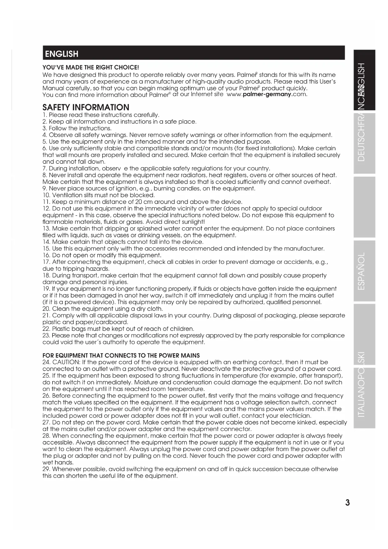
We have designed this product to operate reliably over many years. Palmer® stands for this with its name and many years of experience as a manufacturer of high-quality audio products. Please read this User's Manual carefully, so that you can begin making optimum use of your Palmer® product quickly. You can find more information about Palmer® at our Internet site www.palmer-germany.com.
SAFETY INFORMATION
- Please read these instructions carefully.
- Keep all information and instructions in a safe place.
- Follow the instructions.
- Observe all safety warnings. Never remove safety warnings or other information from the equipment.
- Use the equipment only in the intended manner and for the intended purpose.
- Use only sufficiently stable and compatible stands and/or mounts (for fixed installations). Make certain that wall mounts are properly installed and secured. Make certain that the equipment is installed securely and cannot fall down.
- During installation, observ e the applicable safety regulations for your country.
- Never install and operate the equipment near radiators, heat registers, ovens or other sources of heat. Make certain that the equipment is always installed so that is cooled sufficiently and cannot overheat.
- Never place sources of ignition, e.g., burning candles, on the equipment.
- Ventilation slits must not be blocked.
- Keep a minimum distance of 20 cm around and above the device.
- Do not use this equipment in the immediate vicinity of water (does not apply to special outdoor equipment - in this case, observe the special instructions noted below. Do not expose this equipment to flammable materials, fluids or gases. Avoid direct sunlight!
- Make certain that dripping or splashed water cannot enter the equipment. Do not place containers filled with liquids, such as vases or drinking vessels, on the equipment.
- Make certain that objects cannot fall into the device.
- Use this equipment only with the accessories recommended and intended by the manufacturer.
- Do not open or modify this equipment.
- After connecting the equipment, check all cables in order to prevent damage or accidents, e.g., due to tripping hazards.
- During transport, make certain that the equipment cannot fall down and possibly cause property damage and personal injuries.
- If your equipment is no longer functioning properly, if fluids or objects have gotten inside the equipment or if it has been damaged in anot her way, switch it off immediately and unplug it from the mains outlet (if it is a powered device). This equipment may only be repaired by authorized, qualified personnel.
- Clean the equipment using a dry cloth.
- Comply with all applicable disposal laws in your country. During disposal of packaging, please separate plastic and paper/cardboard.
- Plastic bags must be kept out of reach of children.
- Please note that changes or modifications not expressly approved by the party responsible for compliance could void the user's authority to operate the equipment.
FOR EQUIPMENT THAT CONNECTS TO THE POWER MAINS
- CAUTION: If the power cord of the device is equipped with an earthing contact, then it must be connected to an outlet with a protective ground. Never deactivate the protective ground of a power cord.
- If the equipment has been exposed to strong fluctuations in temperature (for example, after transport), do not switch it on immediately. Moisture and condensation could damage the equipment. Do not switch on the equipment until it has reached room temperature.
- Before connecting the equipment to the power outlet, first verify that the mains voltage and frequency match the values specified on the equipment. If the equipment has a voltage selection switch, connect the equipment to the power outlet only if the equipment values and the mains power values match. If the included power cord or power adapter does not fit in your wall outlet, contact your electrician.
- Do not step on the power cord. Make certain that the power cable does not become kinked, especially at the mains outlet and/or power adapter and the equipment connector.
- When connecting the equipment, make certain that the power cord or power adapter is always freely accessible. Always disconnect the equipment from the power supply if the equipment is not in use or if you want to clean the equipment. Always unplug the power cord and power adapter from the power outlet at the plug or adapter and not by pulling on the cord. Never touch the power cord and power adapter with wet hands.
-
Whenever possible, avoid switching the equipment on and off in quick succession because otherwise this can shorten the useful life of the equipment.
-
IMPORTANT INFORMATION: Replace fuses only with fuses of the same type and rating. If a fuse blows repeatedly, please contact an authorised service centre.
- To disconnect the equipment from the power mains completely, unplug the power cord or power adapter from the power outlet.
- If your device is equipped with a Volex power connector, the mating Volex equipment connector must be unlocked before it can be removed. However, this also means that the equipment can slide and fall down if the power cable is pulled, which can lead to personal injuries and/or other damage. For this reason, always be careful when laying cables.
- Unplug the power cord and power adapter from the power outlet if there is a risk of a lightning strike or before extended periods of disuse.
- The appliance is not to be used by persons (including children) with reduced physical, sensory or mental capabilities, or lack of experience and knowledge.
- Children must be instructed not to play with the device.
- If the power cord of the device is damaged, do not use the device. The power cord must be replaced by an adequate cable or assembly from an authorized service center.
CAUTION:
To reduce the risk of electric shock, do not remove cover (or back). There are no user serviceable parts inside. Maintenance and repairs should be exclusively carried out by qualified service personnel.

The warning triangle with lightning symbol indicates dangerous uninsulated voltage inside the unit, which may cause an electrical shock.

The warning triangle with exclamation mark indicates important operating and maintenance instructions.

Warning! This device is designed for use below 2000 metres in altitude.

Warning! This product is not intended for use in tropical climates.
INTRODUCTION
The Palmer Monicon XL is the perfect tool for controlling multiple audio sources and studio speakers thanks to its ergonomic console layout. It features three analog stereo inputs, an S/PDIF input, and outputs for three pairs of monitors with individual volume controls that allow for level adjustment. There is also a mono output for a special mono speaker or subwoofer. The inputs and outputs can be conveniently controlled using illuminated buttons. A correlation display provides visual information about the mono compatibility of your stereo mixes. Certain functions can be adjusted and their settings saved to help you work the way you want.
Additional features:
- Latency-free and no sound coloration, thanks to analog signal routing
- Two separately controllable headphone outputs with selector switch for main or cue signal
- Integrated talk-back microphone with illuminated button and adjustable dimming function
- Mono button, mute function, and large main volume control
Scope of delivery:
External power supply, user manual
CABLING AND SETUP
Before putting the device into operation, make sure to observe the technical data for all components, such as the maximum output level of player devices and the maximum input level of the monitor controller and monitors! In case of uncertainty, consult an experienced studio technician. Use high-quality and, if possible, balanced cables for cabling. In the following, you will find information about cabling and putting the monitor controller into operation with active studio monitors. The procedure can also be applied to the cabling and setting up with a power amp and passive studio monitors.
- Before you begin installing the cables, turn off any devices that you want to connect to the monitor controller and set the volume of all devices to minimum.
• After installing the cables, turn on the connected monitors and headphone amplifiers as the last devices. - Start playback on the desired player device and activate the appropriate input (INPUT SELECT IN 1 to IN 3). Then check the input signal using the 8-segment LEFT and RIGHT level indicators. If necessary, adjust the display to the input signal level (for description, see point 16).
- Make sure that the controller's MUTE, DIM, and TALK functions are not activated.
- Now activate the monitor output (OUTPUT SELECT OUT 1 to OUT 3) to which your monitors are connected and turn the corresponding GAIN control above the output all the way clockwise (maximum).
- Set the MAIN volume control to the 12 o'clock position and carefully increase the volume of the monitors to the desired monitoring volume, making sure that the monitors are equally loud. Repeat these same steps to adjust a subwoofer's volume to the volume of the monitors.
- Keep the levels of various player devices and pairs of monitors at the same level to avoid sudden jumps in volume when switching signal sources and monitor outputs.
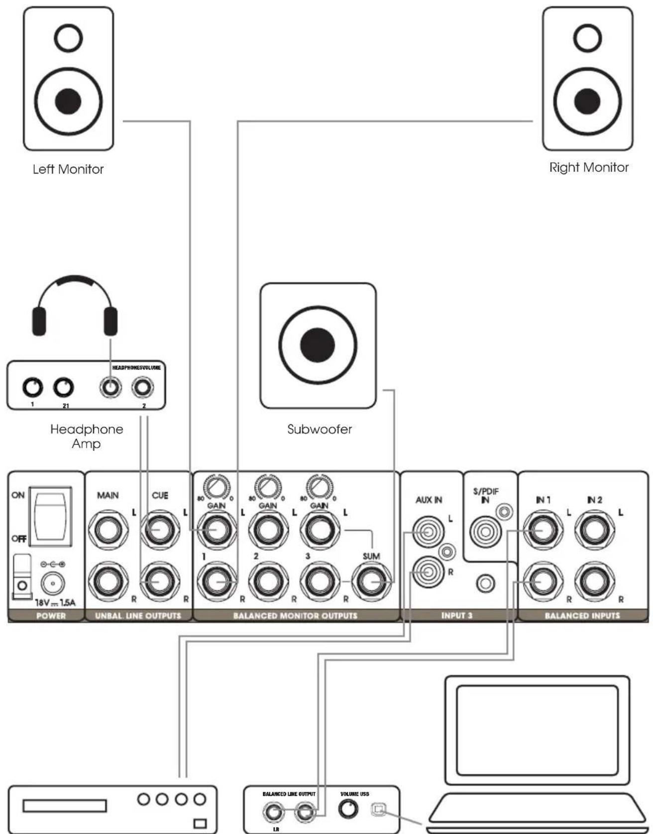
CABLING EXAMPLE
flowchart
graph TD
    A["Left Monitor"] --> B["Headphone Amp"]
    C["Right Monitor"] --> D["Subwoofer"]
    B --> E["POWER"]
    D --> F["UNBAL LINE OUTPUTS"]
    D --> G["BALANCED MONITOR OUTPUTS"]
    D --> H["INPUT 3"]
    D --> I["BALANCED INPUTS"]
    E --> J["18V ~ 1.5A"]
    F --> K["L"]
    G --> L["GAIN"]
    H --> M["AUX IN"]
    I --> N["S/PDIF"]
    J --> O["1"]
    K --> P["R"]
    L --> Q["L"]
    M --> R["R"]
    N --> S["L"]
    O --> T["VOLUME USB"]
    P --> U["LR"]
    Q --> V["1"]
    R --> W["2"]
    S --> X["3"]
    T --> Y["4"]
    U --> Z["5"]
    V --> AA["6"]
    W --> AB["7"]
    X --> AC["8"]
    Y --> AD["9"]
    Z --> AE["10"]
    AA --> AF["11"]
    AB --> AG["12"]
    AC --> AH["13"]
    AD --> AI["14"]
    AE --> AJ["15"]
    AF --> AK["16"]
    AG --> AL["17"]
    AH --> AM["18"]
CD Player Audio Interface
Digital Audio Workstation
CONNECTIONS, CONTROL, AND DISPLAY ELEMENTS

1 POWER
Low-voltage socket to supply power to the device. Please use only the provided power adapter. The strain relief fitting is located next to the socket. Use the strain relief for the power adapter's flexible cable to protect the device's low-voltage socket and the power adapter's low-voltage plug from damage and to avoid pulling out the plug inadvertently.
2 POWER ON/OFF
On/off switch for the device power supply.
3 BALANCED INPUTS IN 1 & IN 2
Balanced stereo line inputs with 0.25 inch jack sockets (IN 1 L+R, IN 2 L+R).
4 INPUT 3
Unbalanced stereo line input with L + R cinch sockets, one 0.14 inch stereo jack socket and one coaxial S/PDIF input. The analog cinch inputs and 0.14 inch jack socket can be used at the same time. In this case, the volume balance must be set on the respective player devices. The digital S/PDIF input can also be used. The control panel on the top of the device is used for analog and digital signal source switching and the level adjustment for IN 3 AUX.
5 BALANCED MONITOR OUTPUTS 1 - 2 - 3
Balanced outputs for connecting active studio monitors and power amps with passive studio monitors. All three outputs are equipped with 0.25 inch TRS jack sockets. In addition to the two L and R sockets, Output 3 provides a mono-summed SUM output for connecting an additional monitor with mono signal or a subwoofer. If necessary, the output level can be configured separately for all three outputs on the corresponding GAIN controller and thus adapted to the connected monitor system.
6 UNBAL. LINE OUTPUTS MAIN - CUE
Unbalanced outputs with 0.25 inch jack sockets
MAIN L/R - connection available for external recording device, such as a tape recorder or a digital stereo recorder. The signal which is selected as the input signal on the control panel for INPUT SELECT (IN 1 to IN 3) is output. The signal is tapped before the MAIN volume control. It therefore functions independently of it and is not influenced by the MUTE, MONO, DIM, and TALK functions.
CUE L/R - connection available for an external headphone amplifier. The signal which is selected as the signal source on the control panel for CUE SOURCE (IN 1 to IN 3) is output. Adjust the signal volume with the CUE OUTPUT volume control on the control panel. The signal is not influenced by the MUTE, MONO and DIM functions, while the TALK function retains its full scope of features.

7 INPUT SELECT IN 1 - IN 2 - IN 3
Buttons for selecting and activating the signal sources Line input IN 1 to IN 3 on the back of the device (No. 3 and No. 4). The button corresponding to the active line input illuminates. You can choose between two modes of operation when selecting the signal source.
Mode of operation A: All signal sources can be selected and activated at the same time (factory default). Before changing the setting, switch off all connected monitors and headphone amplifiers. To select the mode of operation A "Multi mode," switch off the monitor controller, press the IN 1 button on INPUT SELECT, and hold down the button until the monitor controller has been switched on again.
Mode of operation B: A single signal source can be freely selected and activated. The previously activated signal source will be deactivated upon selecting another signal source. To select the mode of operation B "Individual mode," switch off the monitor controller, press the IN 2 button on INPUT SELECT, and hold down the button until the monitor controller has been switched on again.
8 INPUT 3 AUX
Level control to adjust the volume of the INPUT 3 AUX line input.
9 AUX / S/PDIF
Switch for selecting INPUT 3's analog or digital input source. In the switched-down position, the L/R analog cinch input or 0.14 inch stereo jack input is activated; when not switched down, the SPDIF IN digital coaxial connector is activated.
10 OUTPUT SELECT OUT 1 - OUT 2 - OUT 3
Buttons for selecting OUT 1 to OUT 3 line outputs on the back of the device (No. 5). The button corresponding to the active line output illuminates. You can choose between three modes of operation when selecting the line outputs.
Mode of operation A: All line outputs can be selected and activated at the same time (factory default). Before changing the setting, switch off all connected monitors and headphone amplifiers. To select the mode of operation A "Multi mode," switch off the monitor controller, press the OUT 1 button on OUTPUT SELECT, and hold down the button until the monitor controller has been switched on again.
Mode of operation B: A single line output can be freely selected and activated. The previously activated line output will be deactivated upon selecting another line output. To select the mode of operation B "Individual mode," switch off the monitor controller, press the OUT 2 button on OUTPUT SELECT, and hold down the button until the monitor controller has been switched on again.
Mode of operation C: Line output OUT 3 can be switched on or off independently of OUT 1 and OUT 2. OUT 1 and OUT 2 can be selectively activated, but not both at the same time. The previously activated line output will be deactivated upon selecting the corresponding line output. To select the mode of operation C "Combined mode," switch off the monitor controller, press the OUT 3 button on OUTPUT SELECT, and hold down the button until the monitor controller has been switched on again.
11 CUE SOURCE IN 1 - IN 2 - IN 3
Illuminated buttons for selecting the IN 1 to IN 3 signal source for the CUE L/R line output. The button corresponding to the active line input illuminates.
12 CUE OUTPUT
Volume control for the CUE line output (UNBAL, LINE OUTPUTS CUE).
13 MAIN
Volume control for the balanced line outputs BALANCED MONITOR OUTPUTS 1 to 3. Keep the levels of various signal sources at a similar level to avoid sudden jumps in volume when switching signal sources.
14 MONO
Push the MONO button in order to monitor the output signals of the line outputs BALANCED MONITOR OUTPUTS 1 to 3 and the headphone outputs 1 and 2 (MAIN signal) in mono. It is easy to control how a mix sounds in mono because many clubs and bars use sound systems in mono mode. It is also always advisable to listen to a stereo mix in mono because it will allow you to better identify problems with the phasing and to also rectify them.
The MONO function does not affect CUE channel's signal.
The modes of operation for the MUTE, TALK, INPUT SELECT and OUTPUT SELECT buttons can be reset to the factory default by switching off the monitor controller, pressing MONO, and holding it down until the monitor controller has been switched back on again. Before changing the setting, switch off all connected monitors and headphone amplifiers.
15 MUTE
Mute function for the output signals of the line outputs BALANCED MONITOR OUTPUTS 1 to 3 and the head-phone outputs 1 and 2 (MAIN signal). The mute function does not affect CUE channel's signal.
You can choose between two modes of operation for the MUTE function.
Mode of operation A (factory default): "latching" (switch): Push the MUTE button once to activate the function and briefly again to deactivate the function. The MUTE button illuminates when the mute function is activated.
Mode of operation B: "momentary" (button): The MUTE function is only active as long as the MUTE button is pressed. The function automatically deactivates upon releasing the button. The MUTE button illuminates when the MUTE function is activated.
Before changing the setting, switch off all connected monitors and headphone amplifiers.
To select the mode of operation B, switch off the monitor controller, press the MUTE button, and hold it down until the monitor controller has been switched on again.
16 LEFT / RIGHT
8-segment LED level indicators for the left and right channel of the adjacent audio signal; tapping occurs before the MAIN volume control. To improve control, the display can be adjusted to the input signal's signal level in three stages.
Example: The level indicator's red LED 0 illuminates when the level indicator is set to +10 dBu and the input has a signal of +10 dBu.
+18 dBu is the default setting. Before changing the setting, switch off all connected monitors and headphone amplifiers.
+4 dBu - If none of the connected player devices exceeds the maximum output level of +4 dBu, select the setting +4 dBu. Switch off the monitor controller, press the CUE SOURCE IN 1 button, and hold it down until the monitor controller has been switched on again.
+10 dBu - If none of the connected player devices exceeds the maximum output level of +10 dBu, select the setting +10 dBu. Switch off the monitor controller, press the CUE SOURCE IN 2 button, and hold it down until the monitor controller has been switched on again.
+18 dBu - If none of the connected player devices exceeds the maximum output level of +18 dBu, select the setting +18 dBu. Switch off the monitor controller, press the CUE SOURCE IN 3 button, and hold it down until the monitor controller has been switched on again.
The monitor controller's maximum input level is +20 dBu. If the input level goes above this level, it overmodulates the input and distorts the signal. If one of the connected player devices exceeds the maximum output level of +20 dBu, the output level of the respective player device must be restricted to a maximum level of +20 dBu.
17 CORRELATION
Check the stereo audio signal's mono compatibility. Since many clubs and bars operate sound systems in mono, and since, for example, a sound production on the radio should also be played back in good quality on simple mono devices, the mono compatibility of the sound production is extremely important. For a stereo signal's mono playback, the left and right channel are blended to form a mono signal (mono sum). If a sound in the stereo mix is not played back on both channels in phase, it may be distorted or even completely cancelled out during mono playback. In extreme cases, the entire audio signal can be cancelled out altogether (silence).
When reproducing a stereo signal in the mix, ensure that only up to three of the bottom green LEDs of the 7-segment CORRELATION display illuminate, and that none of the top three LEDs illuminate (the more red LEDs illuminate, the worse the mono compatibility). The bottom green LED and middle yellow LED illuminate permanently, even if there is no signal.
18 TALK LEVEL
Press the TALK button to activate the integrated talk-back microphone and to easily communicate with musicians and voice artists using the CUE monitoring channel and the headphone outputs on the front of the device (respective switch in the CUE position). The volume of the talk-back microphone can be controlled with the LEVEL level control above the TALK button. Carefully increase the volume until the connected headphones are at a pleasant level and so that no feedback can happen. Upon activating the talk-back microphone, the CUE SOURCE IN 1 to IN 3 audio signal on the CUE channel and headphone outputs on the front of the device (respective switch in the CUE position) will automatically be lowered by a fixed amount. The audio signal on the BALANCED MONITOR OUTPUTS 1 to 3 line outputs is simultaneously lowered by the value set on the ATTENUATION control.
You can choose between two modes of operation for the TALK function.
Mode of operation A (factory default): "latching" (switch): Press the TALK button once to activate the function and then press it again briefly to deactivate the function. The TALK and DIM buttons illuminate when the TALK function is activated.
Mode of operation B: "momentary" (button): The TALK function is only active as long as the TALK button is pressed. The function automatically deactivates upon releasing the button. The TALK and DIM buttons illuminate when the TALK function is activated.
Before changing the setting, switch off all connected monitors and headphone amplifiers.
To select the mode of operation B, switch off the monitor controller, press the TALK button, and hold it down until the monitor controller has been switched on again.
19 TALK-BACK MICROPHONE
Microphone used for communicating with musicians and voice artists via the CUE monitoring channel and headphone outlets on the front of the device.
20 DIM ATTENUATION
The DIM function allows you to lower the output signals of the BALANCED MONITOR OUTPUTS 1 to 3 line outputs and the 1 and 2 (MAIN signal) headphone outputs by the value set on the ATTENUATION control, without affecting the CUE signals. For example, you can have a conversation in the control room at a low volume without disturbing an ongoing recording. Press the DIM button once to activate the function and then press it again briefly to deactivate the function. The button illuminates when the DIM function is activated.
21 HEADPHONE OUTPUTS 1 AND 2
Headphone outputs with 0.25 inch jack sockets. Use the CUE/MAIN switch on the desired headphone output (switched-down position = CUE signal, not in the switched-down position = MAIN signal) to select the signal source and adjust the volume using the corresponding LEVEL level control. To prevent damage to equipment as well as hearing damage, turn down the volume to minimum before connecting and putting on headphones, and then only gently raise the volume, keeping the levels of the various signal sources at a similar level to avoid sudden jumps in volume when switching sources. The signals are each tapped before the CUE and MAIN volume controls (PFL).
PIN ASSIGNMENT

INDIVIDUAL SETTINGS
Certain functions can be adjusted and their settings saved (see table below) to help you work the way you want. Information about this is also printed in English on the bottom of the device.
| Hold down button while switching on Monicon XL | Mode of operation for corresponding display and operating controls: |
| CUE SOURCE "IN 1" Adjustment of | the LEFT/RIGHT level indicator: Maximum display"0 dB" (red LED) corresponds to +4 dBu input signal level |
| CUE SOURCE "IN 2" Adjustment of | the LEFT/RIGHT level indicator: Maximum display"0 dB" (red LED) corresponds to +10 dBu input signal level |
| CUE SOURCE "IN 3" Adjustment of | the LEFT/RIGHT level indicator: Maximum display"0 dB" (red LED) corresponds to +18 dBu input signal level |
| INPUT SELECT "IN 1" Multi mode: All | NPUT SELECT inputs can be activated at the same time |
| INPUT SELECT "IN 2" Individual mode: | Only one INPUT SELECT input can be activated at a time |
| OUTPUT SELECT "OUT 1" Multi mode: | All OUTPUT SELECT outputs can be activated at the same time |
| OUTPUT SELECT "OUT 2" Individual mode: | Only one OUTPUT SELECT output can be activated at a time |
| OUTPUT SELECT "OUT 3" Combined mode: | OUT 3 activates and deactivates independently OUT 1 and OUT 2 can be selectively activated |
| "MUTE" Switching the MUTE button's mode of operation from switch (latching) to button (momentary) | |
| "TALK" Switching the TALK button's mode of operation from switch (latching) to button (momentary) | |
| "MONO" Reset to factory default | |
TECHNICAL SPECIFICATIONS
| Article number: PMONICONXL | |
| Product type: Studio Equipment | |
| Type: Monitor Controller | |
| Number of outputs: Three controllable and balanced stereo outputs | |
| MONITOR OUTPUTS | |
| One unbalanced stereo CUE output | |
| One unbalanced stereo MAIN output | |
| Two stereo headphone outputs (PHONES) | |
| Output connections: 0.25 inch jack (TRS) | |
| Maximum output level: +25 dBu (balanced), +20 dBu (unbalanced) | |
| Maximum output power of headphones output: 75 mW @ 32 ohm | |
| Output impedance: 600 ohm | |
| Number of inputs: Two balanced stereo inputs | One unbalanced input (cinch + 0.14 inch jack + S/PDIF) |
| Input connections: IN 1 + 2: 0.25 inch jack L+R TRS | IN 3: L+R cinch, 0.14 inch stereo jack, S/PDIF coaxial |
| Maximum input level: +20 dBu | |
| Input impedance: 10 kΩ (balanced), 5 kΩ (unbalanced) | |
| S/PDIF: DA 24 bit (44.1 kHz, 48 kHz, 96 kHz) | |
| Frequency response: 12 Hz to 90 kHz (-1 dB) | |
| Total harmonic distortion (THD): | 0.002 % (BW 20–20,000 Hz) |
| Signal-to-noise ratio (SNR): | 102 dB (A-weighted) @ +4 dBu |
| Dynamic range (DR AES17): | 115 dB |
| CMRR: | better than 55 dB |
| Maximum attenuation: 111 dB (Attenuator + Mute), 86 dB (Attenuator) | |
| Talk-back microphone: Electret capacitor microphone | |
| Control elements: On/off switch, MAIN volume control, INPUT SELECT IN | |
| 1-2-3, OUTPUT SELECT OUT 1-2-3, CUE SOURCE IN 1-2-3, INPUT 3 volume control, INPUT 3 AUX / SPDIF, CUE OUTPUT, PHONES 1+2 LEVEL, PHONES 1+2 MAIN/CUE, MUTE, MONO, DIM, DIM ATTENUATION, TALK, TALK LEVEL, MONITOR OUTPUTS OUT 1-2-3 GAIN | |
| Display elements: | Illuminated button INPUT SELECT IN 1-2-3, OUTPUT SELECT OUT 1-2-3, CUE SOURCE IN 1-2-3, MUTE, MONO, DIM, TALK,8-segment LED level display with peak hold, 7-segment LED correlation display |
| Power supply: External adapter | |
| Operating voltage: | 18 V DC, 1.5 A, + indoor |
| Ambient temperature (running): | 32°F to 104°F |
| Relative humidity: | <80 % (non-condensing) |
| Housing material: | Metal / MDF |
| Housing surface: | Powder-coated / plastic-coated |
| Housing color: | Black |
| Housing design: | Console |
| Dimensions (W x H x D): | 10 x 3.3 x 8.5 inches |
| Weight: | 3.3 lbs |
| Included accessories: | External adapter |
MANUFACTURER'S DECLARATIONS
MANUFACTURER'S WARRANTY & LIMITATIONS OF LIABILITY
You can find our current warranty conditions and limitations of liability at: https://cdn-shop.adamhall.com/media/pdf/MANUFACTURERS-DECLARATIONS_PALMER5bb2340e52a8c.pdf To request warranty service for a product, please contact Adam Hall GmbH, Adam-Hall-Str. 1,
61267 Neu Anspach / Email: Info@adamhall.com / +49 (0)6081 / 9419-0.

CORRECT DISPOSAL OF THIS PRODUCT
(valid in the European Union and other European countries with a differentiated waste collection system)
This symbol on the product, or on its documents indicates that the device may not be treated as household waste. This is to avoid environmental damage or personal injury due to uncontrolled waste disposal. Please dispose of this product separately from other waste and have it recycled to promote sustainable economic activity. Household users should contact either the retailer where they purchased this product, or their local government office, for details on where and how they can recycle this item in an environmentally friendly manner. Business users should contact their supplier and check the terms and conditions of the purchase contract. This product should not be mixed with other commercial waste for disposal.
DEUTSCH
APPAREILS RELIÉS AU SECTEUR
(Valid in the European Union and other European countries with waste separation)


- MONICON XL
- DEUTSCH
- SAFETY INFORMATION
- FOR EQUIPMENT THAT CONNECTS TO THE POWER MAINS
- CAUTION:
- INTRODUCTION
- CABLING AND SETUP
- CONNECTIONS, CONTROL, AND DISPLAY ELEMENTS
- POWER
- POWER ON/OFF
- BALANCED INPUTS IN 1 & IN 2
- INPUT 3
- BALANCED MONITOR OUTPUTS 1 - 2 - 3
- UNBAL. LINE OUTPUTS MAIN - CUE
- INPUT SELECT IN 1 - IN 2 - IN 3
- INPUT 3 AUX
- AUX / S/PDIF
- OUTPUT SELECT OUT 1 - OUT 2 - OUT 3
- CUE SOURCE IN 1 - IN 2 - IN 3
- CUE OUTPUT
- MAIN
- MONO
- MUTE
- LEFT / RIGHT
- CORRELATION
- TALK LEVEL
- TALK-BACK MICROPHONE
- DIM ATTENUATION
- HEADPHONE OUTPUTS 1 AND 2
- INDIVIDUAL SETTINGS
- MANUFACTURER'S DECLARATIONS
- MANUFACTURER'S WARRANTY & LIMITATIONS OF LIABILITY
- CORRECT DISPOSAL OF THIS PRODUCT
- APPAREILS RELIÉS AU SECTEUR
Brand : Palmer
Model : Monicon XL
Category : Audio recorder